

Page 1
Fifth Edition Copyright ©2016
TCG 01-G
USER MANUAL
Page 2

Contents
1. INTRODUCTION ................................................................................................................................................................................. 5
2. FRONT PANEL .................................................................................................................................................................................... 6
LCD Display ............................................................................................................................................................................................................... 6
Contrast Adjustment Mode ......................................................................................................................................................... 8
LED Indicators .......................................................................................................................................................................................................... 8
3. BACK PANEL ..................................................................................................................................................................................... 10
P1: Power Input (2-pin Connector [5.08 mm]) ...................................................................................................................................... 10
Earth Stud (M4 Nut) ........................................................................................................................................................................................... 10
4. BACK PANEL INPUTS AND OUTPUTS .......................................................................................................................... 11
ANT: Antenna Connector (SMA Connector) ......................................................................................................................................... 11
Antenna Cable Considerations: ............................................................................................................................................... 11
P2, P3: Programmable Outputs (2-pin [3.81 mm] / BNC or ST Fiber) ...................................................................................... 11
Electrical and Physical Configuration .................................................................................................................................. 11
P2, P3 Programmable Output Options ............................................................................................................................... 12
P4: Serial Port and Programmable Output (DB9 Connector) ...................................................................................................... 13
P4 Serial Strings ............................................................................................................................................................................... 13
P4-pin 1 Programmable Output .............................................................................................................................................. 13
P5: AM IRIG-B Output (BNC Connector) ................................................................................................................................................. 14
P6: Event Recording / IRIG-B Sync Inputs (4-pin 3.81 mm Connector) ................................................................................. 14
P7: Sync Relay (4-pin 3.81 mm Connector) ............................................................................................................................................ 14
P8: ECP Ethernet Communication Port (RJ45 Connector) ...................................................................................................... 15
5. INSTALLATION ................................................................................................................................................................................ 16
Identification ........................................................................................................................................................................................................... 16
Mounting the TCG 01-G .................................................................................................................................................................................... 16
Operation .................................................................................................................................................................................................................. 16
Event Recording Function ............................................................................................................................................................................... 17
General Description & Specification .................................................................................................................................... 17
Tag Data................................................................................................................................................................................................ 17
Tag Storage ........................................................................................................................................................................................ 17
Tag Retrieval ...................................................................................................................................................................................... 17
TCG 01-G Command / Response Message structure ............................................................................................... 17
TCG 01-G Commands related to Event Time Tagging ............................................................................................. 18
Ps command: Get Status............................................................................................................................................................ 18
TEK-TCG 01-G-Manual-v5-092016 P a g e | 2 www.tekron.com
© 2016 by Tekron International Limited. All Rights Reserved. All trademarks are the property of their respective holders. The
information in this document is provided for informational use only and is subject to change. For further information or support, go to
www.tekron.com.
Page 3

Notes concerning the Ps command: .................................................................................................................................... 19
Pc command: Clear Time-Tag Buffer ................................................................................................................................. 19
Pt command: Get next Time-Tag ......................................................................................................................................... 19
Pr command: Repeat last Tag Sent ..................................................................................................................................... 20
P6 Input Function (IRIG-B / Event Recording) ................................................................................................................................... 20
6. FACTORY HARDWARE OPTIONS ........................................................................................................................................ 22
Power Supply Options ...................................................................................................................................................................................... 22
High Voltage (MOSFET) Output Option ................................................................................................................................................ 22
Lightning Protection Option ......................................................................................................................................................................... 23
General ................................................................................................................................................................................................... 23
Installation ........................................................................................................................................................................................... 23
Disclaimer ............................................................................................................................................................................................ 24
7. APPENDIX ............................................................................................................................................................................................25
TCG 01-G Specifications ................................................................................................................................................................................. 25
Physical Specifications ................................................................................................................................................................25
GNSS Receiver ..................................................................................................................................................................................25
Input and Output Specifications ............................................................................................................................................25
Environmental Specifications ................................................................................................................................................. 26
Electrical Specifications ............................................................................................................................................................. 26
ISOLATION & PROTECTION ........................................................................................................................................................................ 27
SERIAL OUTPUT STRINGS ........................................................................................................................................................................... 28
NGTS Time Code O/P on P4 ................................................................................................................................................... 28
IRIG J-17 Time Code O/P on P4 ............................................................................................................................................. 28
String-A Time Code O/P on P4 .............................................................................................................................................. 29
String-B Time Code O/P on P4 .............................................................................................................................................. 29
String-C Time Code O/P on P4 .............................................................................................................................................. 30
String-D Time Code O/P on P4 ............................................................................................................................................... 31
String-E Time Code O/P on P4 ............................................................................................................................................... 31
String-F Time Code O/P on P4 ............................................................................................................................................... 32
String-G Time Code O/P on P4 ............................................................................................................................................... 32
NMEA ZDA Time Code O/P on P4 ....................................................................................................................................... 34
NMEA RMC Time Code O/P on P4 .......................................................................................................................................35
8. WARRANTY ....................................................................................................................................................................................... 36
TEK-TCG 01-G-Manual-v5-092016 P a g e | 3 www.tekron.com
© 2016 by Tekron International Limited. All Rights Reserved. All trademarks are the property of their respective holders. The
information in this document is provided for informational use only and is subject to change. For further information or support, go to
www.tekron.com.
Page 4

TEK-TCG 01-G-Manual-v5-092016 P a g e | 4 www.tekron.com
© 2016 by Tekron International Limited. All Rights Reserved. All trademarks are the property of their respective holders. The
information in this document is provided for informational use only and is subject to change. For further information or support, go to
www.tekron.com.
Page 5
1. INTRODUCTION
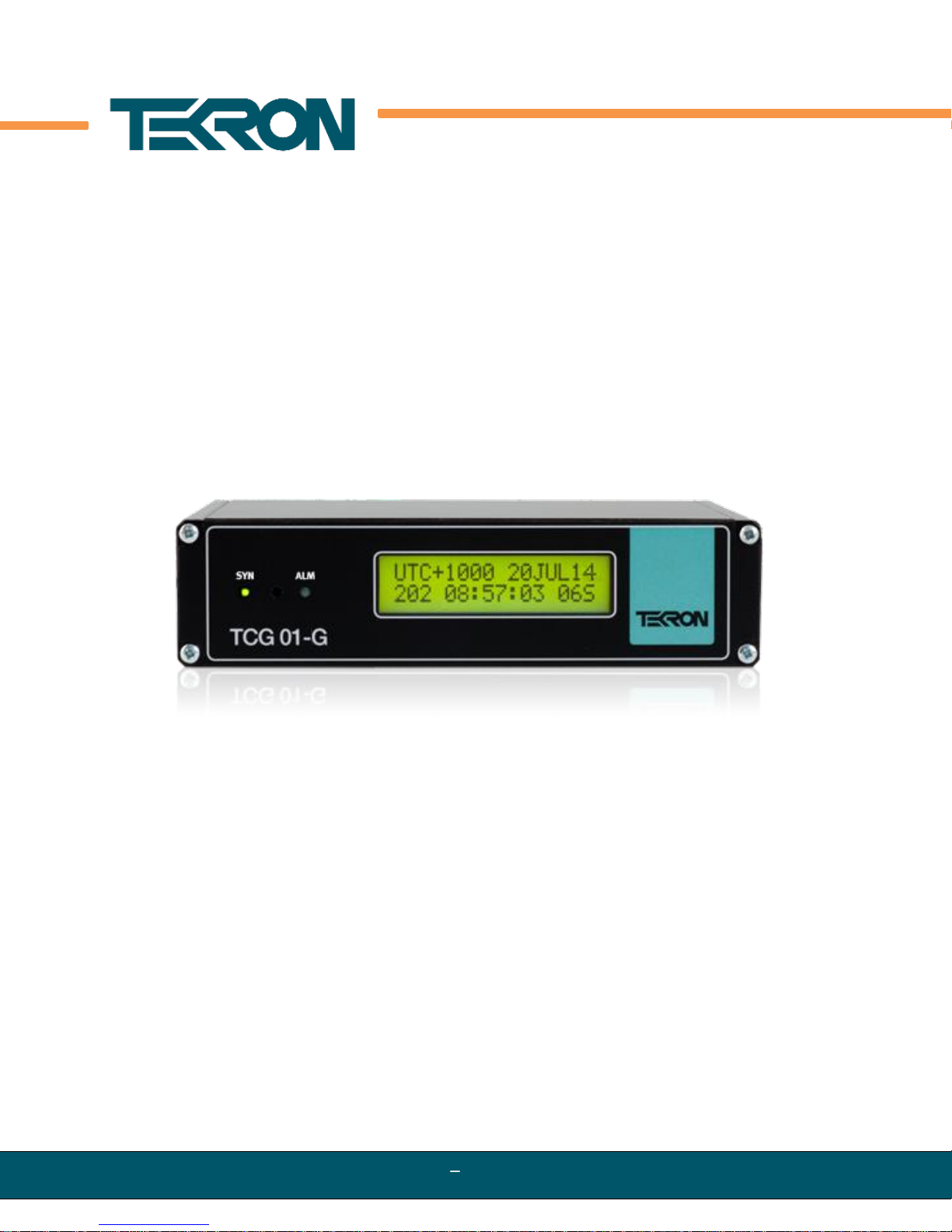
The TCG 01-G Time Code Generator produces precision time code signals, serial strings and pulses
for use in synchronizing industrial control and SCADA equipment. The clock is ideally suited to
providing time synchronization simultaneously to many different devices, such as Phasor
Measurement Units (PMUs), Protection Relays, Remote Telemetry Units (RTUs) and other Intelligent
Electronic Devices (IEDs) used in electrical sub-stations and industrial control installations.
The TCG 01-G features one amplitude modulated (AM) IRIG-B output and three user-programmable
outputs, including a serial port. The serial port is user-configurable to output serial strings and
report event data for units fitted with event recording capability. Factory options include a choice of
physical connectors: BNC, 2-pin plug and socket, or ST Fiber. Non-fiber outputs can be ordered as
TTL, RS422/485, or high voltage switching.
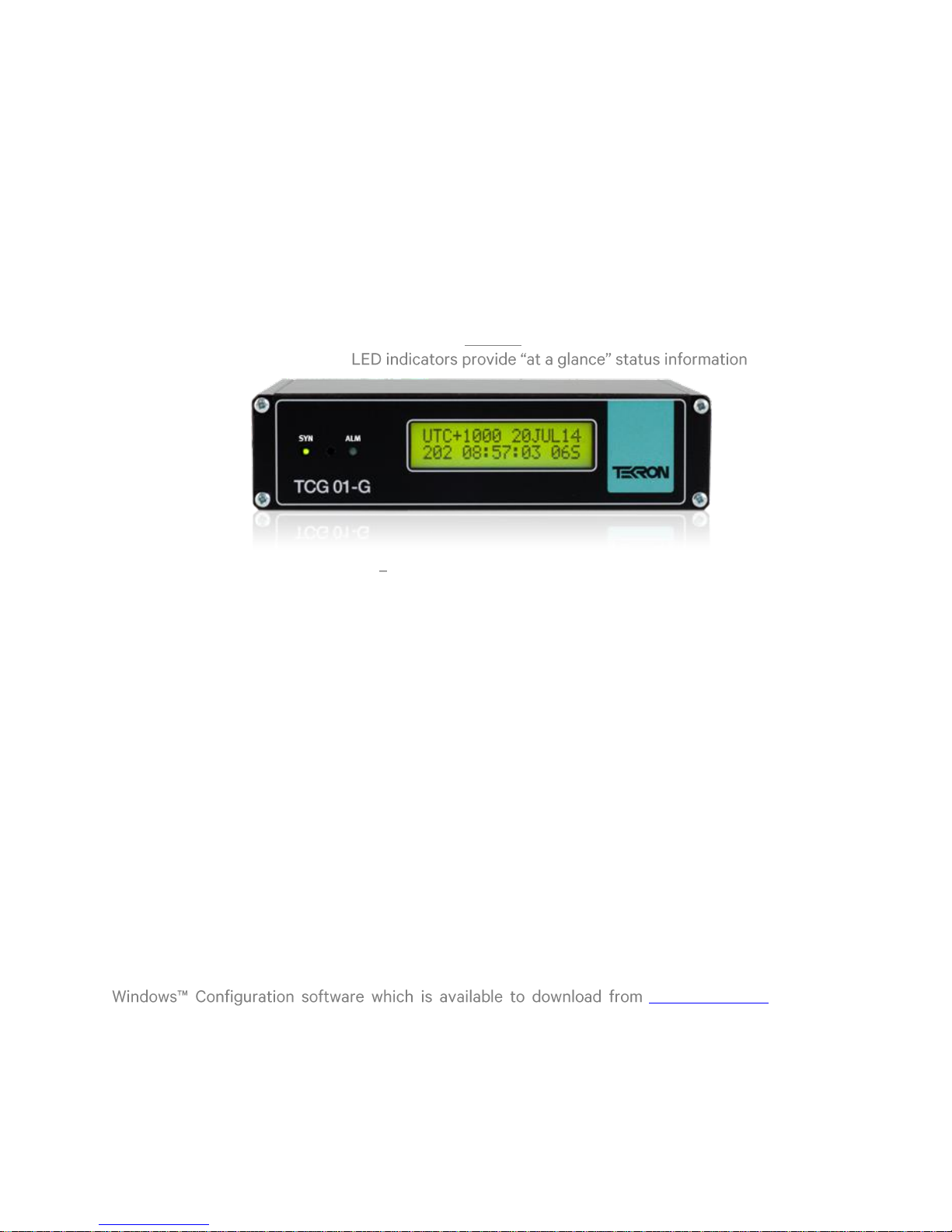
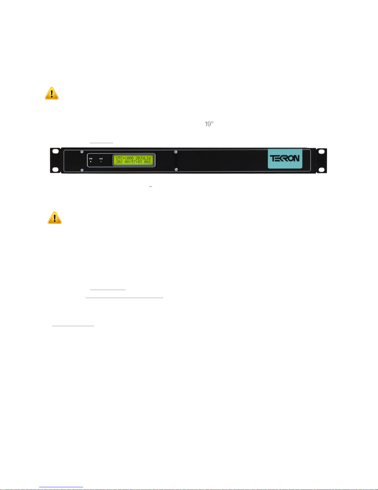
All TCG 01-G units feature a front panel display (Figure 1) giving visual feedback about the time data
being generated on the outputs. .
Figure 1 TCG 01-G chassis and front panel
The optimized receiver/antenna system used by TCG 01-G obtains time with near-atomic clock
precision from the available Global Navigation Satellite Systems (GNSS). The result is output timing
accuracy similar to that normally seen only in laboratory instruments.
However, unlike laboratory instruments, TCG 01-G is suited for hostile electromagnetic environments
such as sub-stations and electrical switchyards. Each output of the TCG 01-G is isolated from every
other output, so that attached wiring can feed out to operating areas in different earth potential
zones without compromising the overall site earthing security. In addition, isolation protects the
internal electronics from longitudinal transient voltages and transient suppression devices protect
from transverse transient voltages.
The TCG 01-G features a 10/100Mb Ethernet port through which the unit can be configured.
Firmware license options include a stratum 1 NTP server and IEEE 1588 V2 functionality. When the
IEEE 1588 (PTP V2) option is enabled, the unit can operate as a PTP Grand Master, an ordinary PTP
clock, or a Slave-Only Clock.
The TCG 01-G has automatic IRIG-B slave functionality which allows the TCG 01-G to accept two
DCLS IRIG-B signals for synchronizing purposes. This function provides automatic selection of the
synchronization source.
It comes complete with Ethernet cables to allow for customization and easy setup from the
www.tekron.com. Optional
accessories include antenna, low loss antenna cable, antenna pipe mounting components and
lightning protection kit.
TEK-TCG 01-G-Manual-v5-092016 P a g e | 5 www.tekron.com
© 2016 by Tekron International Limited. All Rights Reserved. All trademarks are the property of their respective holders. The
information in this document is provided for informational use only and is subject to change. For further information or support, go to
www.tekron.com.
Page 6
2. FRONT PANEL
3a Start Up (Clock ID)
3b Waiting for Satellites
3c Operating Default
3d Local Time
3e UTC Time
3f Alarm
TCG01G Ver F01.XX
(C) 2014 Sn18748
WAITING FOR SATS
GNSS RX STAT: 00A
UTC+1200 17MAR10
076 11:16:53 87A
LST: TUE 17 MAR10
076 11:16:53 87A
UTC: MON 16 MAR10
075 23:16:53 87A
*** ANT ***
075 23:16:53 87A
Figure 2 TCG 01-G front panel
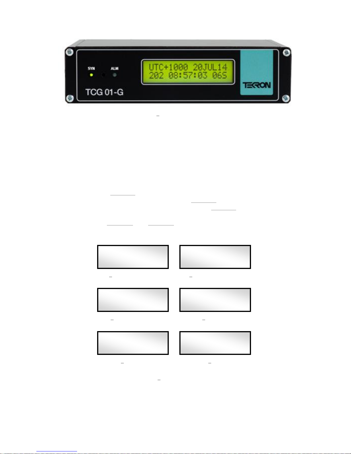
TCG 01-G features two LED indicators on the front panel (Figure 2), together with a 2-line by 16character backlit LCD display.
SYN LED: This LED shows the status of the current sync source.
ALM LED: This LED shows the alarm status of the TCG 01-G.
LCD Display
On initial power-up, the LCD display shows a copyright message, along with the serial number and
revision level of the unit (Figure 3a). Approximately 10 seconds after power-up, the display changes
automatically to indicate that it is waiting for satellites (Figure 3b). Once one or more satellites have
been discovered, it transitions to the operating default display (Figure 3c). After which, the user can
access alternative time displays by pushing the button on the front panel between the LED
indicators, as shown in Figure 3d and Figure 3e. Successive button-pushes can be used to cycle
through all the display screens in turn. The screen display examples below all show the same instant
in time.
TEK-TCG 01-G-Manual-v5-092016 P a g e | 6 www.tekron.com
© 2016 by Tekron International Limited. All Rights Reserved. All trademarks are the property of their respective holders. The
information in this document is provided for informational use only and is subject to change. For further information or support, go to
www.tekron.com.
Figure 3 LCD display screens
Page 7

. The top line of
Character
Values
Description
Satellites in
the sky
- - 9
- -14
This character represents the total number of satellites currently
present in the sky according to the GNSS
position means that TCG 01-G has lost its knowledge of the
GNSS
been in storage for an extended period, or if the GNSS receiver
has been reset. It will typically take 20 minutes (worst case two
hours) for the unit to gain sufficient GNSS synchronization for
the TCG 01-G to recommence normal operation (Position hold).
Satellites
tracked
- - 9
- -14
This digit represents the number of satellites currently being
hat no
Receiver
status
TCG 01-G in Acquisition mode - attempting to get satellite fixes.
straight line so best accuracy cannot be obtained, but the unit
will still sync to UTC.
A 2D position is in use (no height). This may occur before
Position Hold mode has been reached if only 3 satellites are
tracked. Synchronization is not compromised.
Satellites in sky
Satellites tracked
Receiver status
LST: TUE 17 MAR10
076 11:16:53 87A
screen in Figure 3c
with local date. The local time day-of-year and time-of-day are on the bottom line.
Figure 3c shows that the clock is operating with a local time offset of 12 hours ahead of UTC. The
local date is 17th March 2010, and the local time is 11:16:53 in the morning.
Figure 3d shows the same time and date, but also indicates that the time displayed is Local Standard
Time, and that the day is Tuesday. . If daylight savings time is
3d .
Figure 3e shows the UTC time and date which is 11:16:53 on the evening of Monday, 17th March 2010.
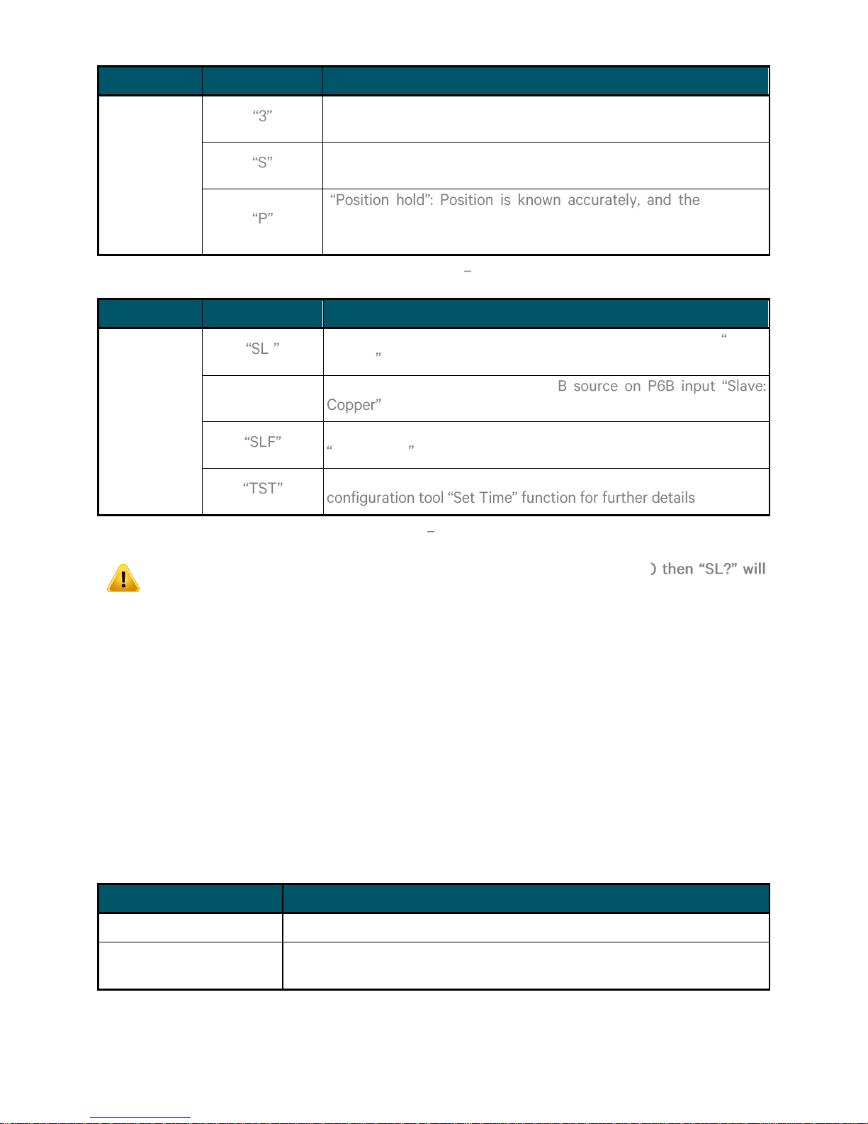
The display screens in Figure 3b, 3c, 3d and 3e each show a three-character status field at the
bottom right-hand side of the display. This three-character field provides feedback on the
parameters that affect the operation of the GNSS receiver and are explained in Figure 4.
Figure 4 Satellite tracking status
TEK-TCG 01-G-Manual-v5-092016 P a g e | 7 www.tekron.com
© 2016 by Tekron International Limited. All Rights Reserved. All trademarks are the property of their respective holders. The
information in this document is provided for informational use only and is subject to change. For further information or support, go to
www.tekron.com.
Page 8
Character
Values
Description
A 3D position is in use, which includes height. A site survey
begins next, so this mode is rarely seen.
Site Survey in progress. TCG 01-G is calculating an accurate
position; once complete the mode will change to Position hold.
GNSS is
providing its most accurate time, typically better than 40 ns to
UTC.
Display Status Table 1a GNSS Status
Character
Values
Description
Alternate
Sync Source
1
Clock is synchronized to an IRIG-B source on P6A input Slave:
Copper
"SL2"
Clock is synchronized to an IRIG-
Clock is synchronized to an IRIG-B source on the Fiber input
Slave: Fiber
Clock is operating with manually set time. Please refer to
State
Description
off
The TCG 01-G has no power
on
The TCG 01-G is synchronized to the source indicated by the LCD
display
Display Status Table 1b Alternative Sync Source
If the clock is configured to synchronize to IRIG-B only (ignore GNSS
be displayed in the status field if there is no IRIG-B signal input.
Contrast Adjustment Mode
The LCD contrast can be adjusted by entering the Contrast Adjustment Mode. This mode is entered
by double pressing the button on the front panel.
Once in Contrast Adjustment Mode, pressing the button will lighten the contrast and decrease the
contrast by one level. There are five different contrast levels and the LCD will cycle from the lightest
to darkest if the button is pressed when on the lightest setting.
To exit the Contrast Adjustment Mode, simply double-press the button on the front panel again. The
button will return to normal operations after this.
LED Indicators
The SYN LED shows the status of the sync source. The various states are shown as follows:-
TEK-TCG 01-G-Manual-v5-092016 P a g e | 8 www.tekron.com
© 2016 by Tekron International Limited. All Rights Reserved. All trademarks are the property of their respective holders. The
information in this document is provided for informational use only and is subject to change. For further information or support, go to
www.tekron.com.
Page 9
Slow Flash (1 per second)
The TCG 01-G running)
Fast Flash (5 per second)
The TCG 01-G
LED Indicators Table 2 SYN LED
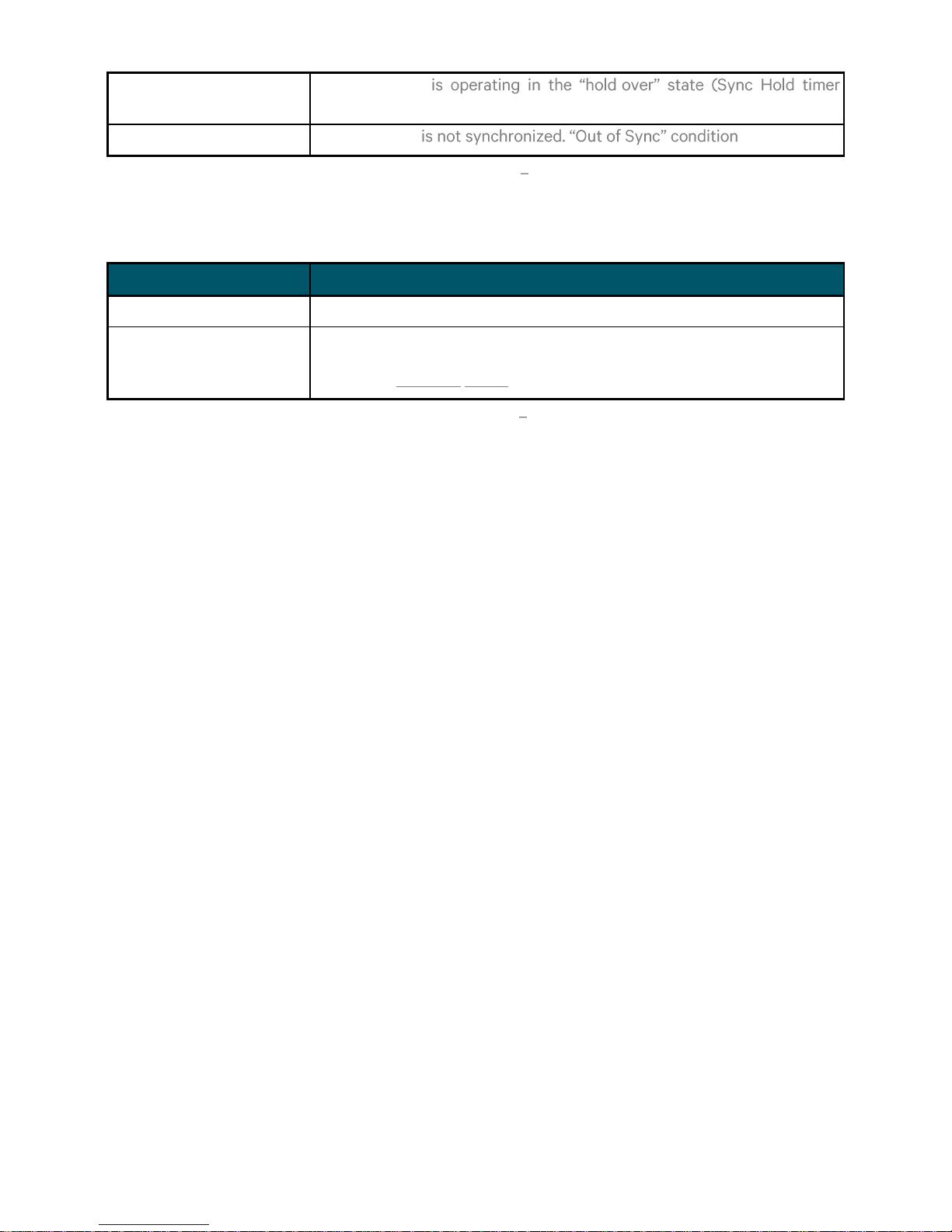
State
Description
off
The TCG 01-G is operating normally. i.e., there are no alarms
Fast Flash (5 per second)
Alarms are active. In this case, the actual alarm state is shown on the top
line of the LCD display, replacing the normal date information (see
example in Figure 3f above).
The ALM LED indicates the internal alarm status of the TCG01-G. It has only two operating states:-
LED Indicators Table 3 ALM LED
TEK-TCG 01-G-Manual-v5-092016 P a g e | 9 www.tekron.com
© 2016 by Tekron International Limited. All Rights Reserved. All trademarks are the property of their respective holders. The
information in this document is provided for informational use only and is subject to change. For further information or support, go to
www.tekron.com.
Page 10
3. BACK PANEL
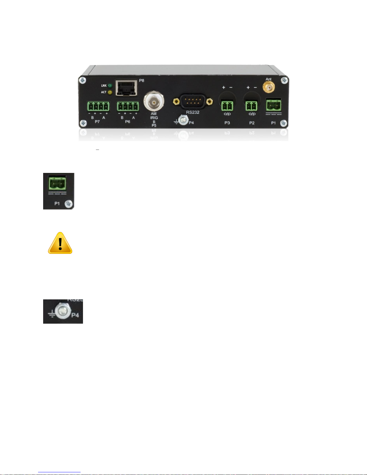
An example TCG 01-G back panel is shown in Figure 5 below. Its appearance may vary, as different
connector types can be fitted at the factory to suit your requirements.
Figure 5 Rear panel of TCG 01-G, configured with 2-pin connectors (P2 and P3)
P1: Power Input (2-pin Connector [5.08 mm])
Power is applied to the unit via this plug. Maximum steady state power consumption is
6 W, and surge protection is provided. A mating connector is supplied that is suitable
for wiring up to 1.5 mm2.
Note that the DC input is protected against incorrect power supply polarity.
The power supply inputs are isolated from earth so that any earthing system is
acceptable (PEN, positive earth, negative earth or non-earthed low voltage
supply).
Check the label on the unit base for power supply voltage rating!
Earth Stud (M4 Nut)
Located under the serial port, to the left of the P4 designator is a M4 bolt provided
for earthing. An external ground connection must be connected to ensure
appropriate grounding for the unit.
TEK-TCG 01-G-Manual-v5-092016 P a g e | 10 www.tekron.com
© 2016 by Tekron International Limited. All Rights Reserved. All trademarks are the property of their respective holders. The
information in this document is provided for informational use only and is subject to change. For further information or support, go to
www.tekron.com.
Page 11
4. BACK PANEL INPUTS AND OUTPUTS
CNT-240
32.8 dB/100 m (10dB/100ft). Plus 1 dB/connector
Approx. Optimum Length Range: 18 to 42 meters
Approx. Maximum Length Range: 12 to 70 meters
CNT-400
16.73 dB/100 m. Plus 1 dB/connector
Approx. Optimum Length Range: 34 to 79 meters
Approx. Maximum Length Range: 23 to 129 meters
Electrical
Electrical Specification
Physical
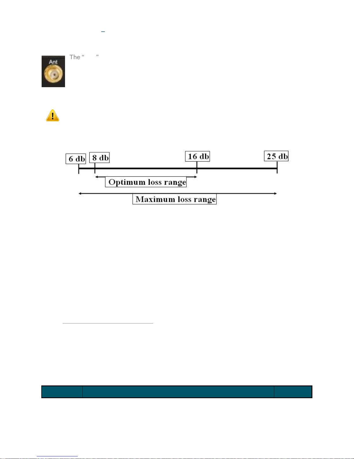
ANT: Antenna Connector (SMA Connector)
ANT is the GNSS antenna input port. The antenna port provides an interface for an
external active antenna via low-loss coaxial cable: 50 Ω impedance. 5 V DC @ 50 mA max
is supplied to power an active antenna. The total combined gain of the antenna system
(antenna plus cable and connectors) should fall in the range of 10 to 35 dB, the optimum
being 22 dB.
If the Fiber-Slave option is ordered, the antenna is replaced by a fiber input port.
Care should be taken to ensure that the connector is not cross-threaded when
attaching the antenna lead-in cable. The connector should be tightened firmly by
hand only. Do NOT over-tighten!
Antenna Cable Considerations:
Note: The following figures are based on an average GNSS signal strength of -130dBm at sea level.
A lightning protection device should be inserted into the antenna lead. A suitable device complete
with additional cable connectors, a connector crimping tool and mounting hardware is available as an
option (FACTORY HARDWARE OPTIONS). Introduction of the lightning protector does not degrade
the performance of the antenna system.
P2, P3: Programmable Outputs (2-pin [3.81 mm] / BNC or ST Fiber)
Electrical and Physical Configuration
Each output port may be fitted at the factory according to the following:
TEK-TCG 01-G-Manual-v5-092016 P a g e | 11 www.tekron.com
© 2016 by Tekron International Limited. All Rights Reserved. All trademarks are the property of their respective holders. The
information in this document is provided for informational use only and is subject to change. For further information or support, go to
www.tekron.com.
Page 12

Electrical
Electrical Specification
Physical
TTL
CMOS/TTL (5 V) logic level driver output ports, 150 mA sink and
source. The port is fully floating and has independent electrical
isolation to 2.5 kV.
2-pin
or BNC
RS422
High Speed RS422/485 (5 V differential) output ports. The port is
fully floating and has independent electrical isolation rated to 2.5 kV.
2-pin
HV MOSFET
Power MOSFET Switch, allowing switching of 300 VA, 1 A max. The
port is fully floating and had independent electrical isolation rated to
2.5 kV. Refer to Figure 11 for suggested wiring configurations for use
with Power MOSFET switching.
2-pin
Fiber
ST fiber transmitters, compatible with ST-terminated 62.5 μm fiber
diameter, 125 μm jacket diameter multi-mode fiber optic cabling.
The maximum length of fiber recommended is 750 m.(λ=820 nm)
ST Fiber
Figure 6 2-pin connector
Figure 7 BNC connector
Figure 8 Fiber connector
Examples of the three connector types are given in (Figure 6) to (Figure 8);
P2, P3 Programmable Output Options
The user may configure P2 and P3 to output in either inverted or non-inverted polarity:
A configurable number of pulses per second, minute, hour, day with adjustable pulse-width
and offset.
IRIG-B and DCF-77 time codes.
TEK-TCG 01-G-Manual-v5-092016 P a g e | 12 www.tekron.com
© 2016 by Tekron International Limited. All Rights Reserved. All trademarks are the property of their respective holders. The
information in this document is provided for informational use only and is subject to change. For further information or support, go to
www.tekron.com.
Page 13

P4: Serial Port and Programmable Output (DB9 Connector)
If not requested otherwise, the TCG 01-G is normally shipped as a DCE
- Socket-to-Socket 9-way data cable
can be used to connect directly to a standard PC serial port. A suitable 2 m
cable is included with each TCG 01-G purchase. The CTS and DSR lines are
permanently asserted. As the serial outputs are usually precisely timed
messages, there is no provision for either hardware or software flow control.
Do NOT over-tighten the securing screws of the connector!
The following signals are present on P4 (DCE configuration only):
Pin 1: RS232 level (-9V to +9V) programmable output.
Pin 2: RS232 level serial string.
Pin 5: RS232 signal ground.
Pin 4 & Pin 6: RS422 level 5V) differential programmable output.
Pin 8 & Pin 9: RS422 level serial string.
The RS232/RS422 signal lines are not isolated from each other, but the port as a whole has an
isolation rating of 2.5 kV from all other ports.
P4 Serial Strings
The serial port can be configured to output any one of a number of different serial time messages on
a broadcast basis. The serial port runs at a user configurable data rate between 1200 and 38400 bps
(available rates are 1200, 2400, 4800, 9600, 19200 and 38400 bps). Message formats typically
operate at 9600 baud, 8-bit with no parity, no flow control and 1 stop bit. Most messages are
transmitted once per second.
A wide range of message strings and protocols can be output on this port. They include:
NTS protocol (transmits once per minute)
IRIG J-17
Seven pre-set messages, String/Tekron A G for compatibility with most IED.
NMEA ZDA and RMC messages
GNSS Binary/Messages, these are subject to change without notice.
See Appendix (SERIAL OUTPUT STRINGS) for details on each of the message string formats.
A common application for the programmable output on P4-pin 1 (RS232 level) is to provide an
independent drive to an RS232-Fiber converter unit for use in transporting time-code/pulse signals
to a distant location. (Tekron manufactures a range of interface devices (ITRs) that include such
converters. -way cable optionally used to
connect to an external PC, and used in conjunction with pin 5 (signal return).
P4-pin 1 Programmable Output
The user may configure the P4-pin 1 output to operate with inverted or non-inverted polarity, and:
A user-configurable number of pulses per second, minute, hour, day with adjustable
pulse-width and offset.
IRIG-B and DCF-77 time codes.
TEK-TCG 01-G-Manual-v5-092016 P a g e | 13 www.tekron.com
© 2016 by Tekron International Limited. All Rights Reserved. All trademarks are the property of their respective holders. The
information in this document is provided for informational use only and is subject to change. For further information or support, go to
www.tekron.com.
Page 14

P4-pin 1 is not available on TCG 01-G with DTE serial ports. If not specified, TCG 01-G
will ship with a DCE serial port.
P5: AM IRIG-B Output (BNC Connector)
P5 provides AM IRIG-B (B12x) over a BNC connector. This output is not programmable
for other types of signal and a 1 kHz carrier is present whenever the unit is powered.
The particular IRIG-B data content is as specified by the configuration program.
Use either a coaxial cable or a shielded twisted pair, to feed signal from P5 to any
connected IED. When using shielded twisted pair, connect the shield to ground.
The mark/space amplitude modulation ratio is 3:1, and peak to peak output level is 8 V
(max), 120 Ω impedance. The output is fully floating, and is transformer-isolated to 3.75 kV.
Most devices with amplitude-modulated IRIG-B time sync inputs have an input
impedance of between 4 kΩ and 20 kΩ, and a maximum allowable peak-to-peak level
of approximately 6 V. The P5 output on the TCG 01-G is designed to drive multiple
devices in parallel, with a terminating resistor (typically 100-180 Ω) fitted at the far
end of the coax line feeding all of the attached loads. In this way P5 can drive at least
20, and typically 30 or more devices (dependent upon layout, device input impedance,
etc.), without any external amplification. The terminating resistor is essential to
ensure good noise immunity and correct voltage levels.
P6: Event Recording / IRIG-B Sync Inputs (4-pin 3.81 mm Connector)
The pluggable connector provides two input channels that may be driven by TTL
sources. The input can be either a pulse for event recording or un-modulated IRIGB (B004 + IEEE1344 extensions) for GNSS sync backup. The input type is software
configurable. If both event recording and IRIG-B sync input functions are selected,
-B sync input.
-
symbols represent the positive and negative terminals respectively. Wiring size is up to 1.00 mm².
The two ports are isolated from the rest of the system by a 2.5 kV barrier and the ports have a 60
VDC isolation from each other. Each input is protectively clamped to 25 V and uses a 470 Ω resistor
to limit the current.
P7: Sync Relay (4-pin 3.81 mm Connector)
P7 provides two alarm output channels.
P7 A is GNSS signals receive fail (Antenna fail) alarm. The antenna alarm only
occurs after a continuous 5 seconds with the antenna disconnected.
P7 B is a synchronization fail alarm. This alarm is triggered if the TCG 01-G is
unable to synchronize to any incoming time source. TCG 01-G will synchronize to
UTC time derived from GNSS, if GNSS reception is available. In the absence of GNSS, the unit will
then attempt to sync to an IRIG-B time source connected via the P6A and/or P6B inputs (P6A takes
TEK-TCG 01-G-Manual-v5-092016 P a g e | 14 www.tekron.com
© 2016 by Tekron International Limited. All Rights Reserved. All trademarks are the property of their respective holders. The
information in this document is provided for informational use only and is subject to change. For further information or support, go to
www.tekron.com.
Page 15
priority over P6B). If the unit is optioned for PTP operation, it can also sync to time from a distant
PTP Master clock.
If all sync is lost, the TCG 01-
(configurable in the Configuration Tool).
the alarm condition is signaled. When sync is restored, the alarm condition is retained for 5 seconds
before being cancelled.
The alarm outputs are Type A (normally-open) dry contact types (implemented using solid state
relays). Normally-Open -energized state of the relay. The
convention used in the TCG 01-G is to have the alarm relays energized during normal operation, and
de-energized in the alarm state. In the case of all power to the clock being lost, all of the alarm relays
act). The + and - symbols represent the positive and
negative terminals respectively. The wiring size is up to 1.00 mm²; contact rating: 200 V, 150 mA DC
or 150 V, 100 mA AC.
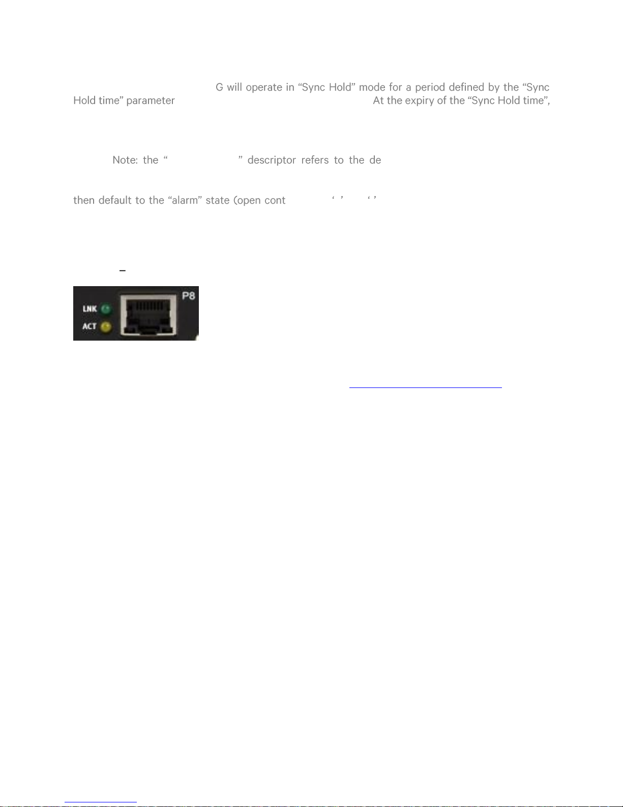
P8: ECP Ethernet Communication Port (RJ45 Connector)
The Ethernet port (ETH1), features a RJ45 connector and supports
10/100 Mbps, Auto MDX & Auto Negotiate. The LEDs convey Link (LNK)
and Activity (ACT) status for the port.
The LNK LED will be on when the unit is connected to a valid Ethernet
port whilst the ACT LED will be on when there is activity on either the transmit or receive pair.
This port is also used to configure the clock via the Tekron Configuration Tool which is available for
download on the TCG 01-G page on the Tekron website at http://www.tekron.com/tcg-01-g.
TEK-TCG 01-G-Manual-v5-092016 P a g e | 15 www.tekron.com
© 2016 by Tekron International Limited. All Rights Reserved. All trademarks are the property of their respective holders. The
information in this document is provided for informational use only and is subject to change. For further information or support, go to
www.tekron.com.
Page 16
5. INSTALLATION
Identification
Each TCG 01-G unit is shipped with identification labels on the base and side. The label provides
details of the particular options fitted to the unit, the power supply requirement, the serial number
and firmware revision.
Check the identification label on the base of the unit to ensure that the correct model
has been supplied before proceeding to install!
Mounting the TCG 01-G
The clock can be used free-standing or mounted in a rack. Each unit ships with a rack-mount
bracket which can be attached by removing the 4 corner front panel screws and attaching the plate
as illustrated in Figure 9.
Figure 9 TCG 01-G with rack-mount bracket
Operation
Check the label on the base for voltage requirements before switching on!
Connect the antenna lead and the antenna (with a good view of the sky). Then connect the power
source to P1.
The time required that will achieve tracking and synchronization given a good view of the sky is
typically within a minute. Reactivating a unit that was previously synchronized thousands of
kilometers away from the present position will take longer but not more than 45 minutes.
As described in LCD Display, the button on the front panel will toggle the display on the LCD and can
also enter the Contrast Adjustment Mode.
Once powered up, the operator can determine correct operation of the TCG 01-G by observing the
LEDs. The ALM LED should be off and the SYN LED should be on solid. If the LEDs are flashing, refer
to LED Indicators for an explanation of the status.
To reset the unit, the power must be cycled. To cycle the power, it is recommended that the external
power source switch that the device the TCG 01-G is connected to; is turned OFF, wait a full ten
seconds, and then turned ON again. This will result in the TCG 01-G having to resynchronize with the
GNSS satellites.
TEK-TCG 01-G-Manual-v5-092016 P a g e | 16 www.tekron.com
© 2016 by Tekron International Limited. All Rights Reserved. All trademarks are the property of their respective holders. The
information in this document is provided for informational use only and is subject to change. For further information or support, go to
www.tekron.com.
Page 17
Event Recording Function
General Description & Specification
TCG 01-G clocks can provide event recording channels on each channel of P6 . The P6 inputs A and
B are TTL level inputs with an input burden of 7 mA.
Recorded time tags contain timestamps corresponding to the rising edge of a pulse. The minimum
pulse duration is 1 µs, and the maximum rate of time tag recording is 100 tags per second
(aggregated over both inputs). In the event of pulses occurring simultaneously on both inputs, both
events are captured and recorded independently with the same time data.
The event recording option makes use of the same input connector (P6) as the
external IRIG-B input function.
Tag Data
Time tags use UTC time, and each tag includes the year, day of year, hour, minute and second, as
well as fraction of second to a resolution and accuracy of 100 ns. TCG 01-G measures time internally
in 40 ns intervals, rounding to the nearest 100 ns for time tag storage purposes, thus allowing
accuracy to equate to resolution. Each tag record includes the input channel number, as well as the
clock sync status as at the tag time.
Tag Storage
TCG 01-G stores time tags in a data queue designed as a circular buffer. The maximum number of
time tags that may be stored is 512.If further events occur when the buffer is full, TCG 01-G sets an
overflow status and continues storing tags, overwriting the oldest data first.
Tag Retrieval
The user can retrieve time tags from the buffer using a request/response protocol operating over
TCG 01- serial port interface. Tags are retrieved from the buffer - oldest data first.
TCG 01-G can be configured to broadcast either status or serial time strings over the serial port.
Most users of the time tag option will want to suppress all broadcast outputs to simplify the task of
time tag data collection. However, if output strings are selected, then TCG 01-G will still output time
tag information when requested, timing the responses to avoid interference with the other traffic on
the port.
TCG 01-G Command / Response Message structure
Units equipped with the event recording option provide four command/response message pairs that
specifically support time tag management and retrieval.
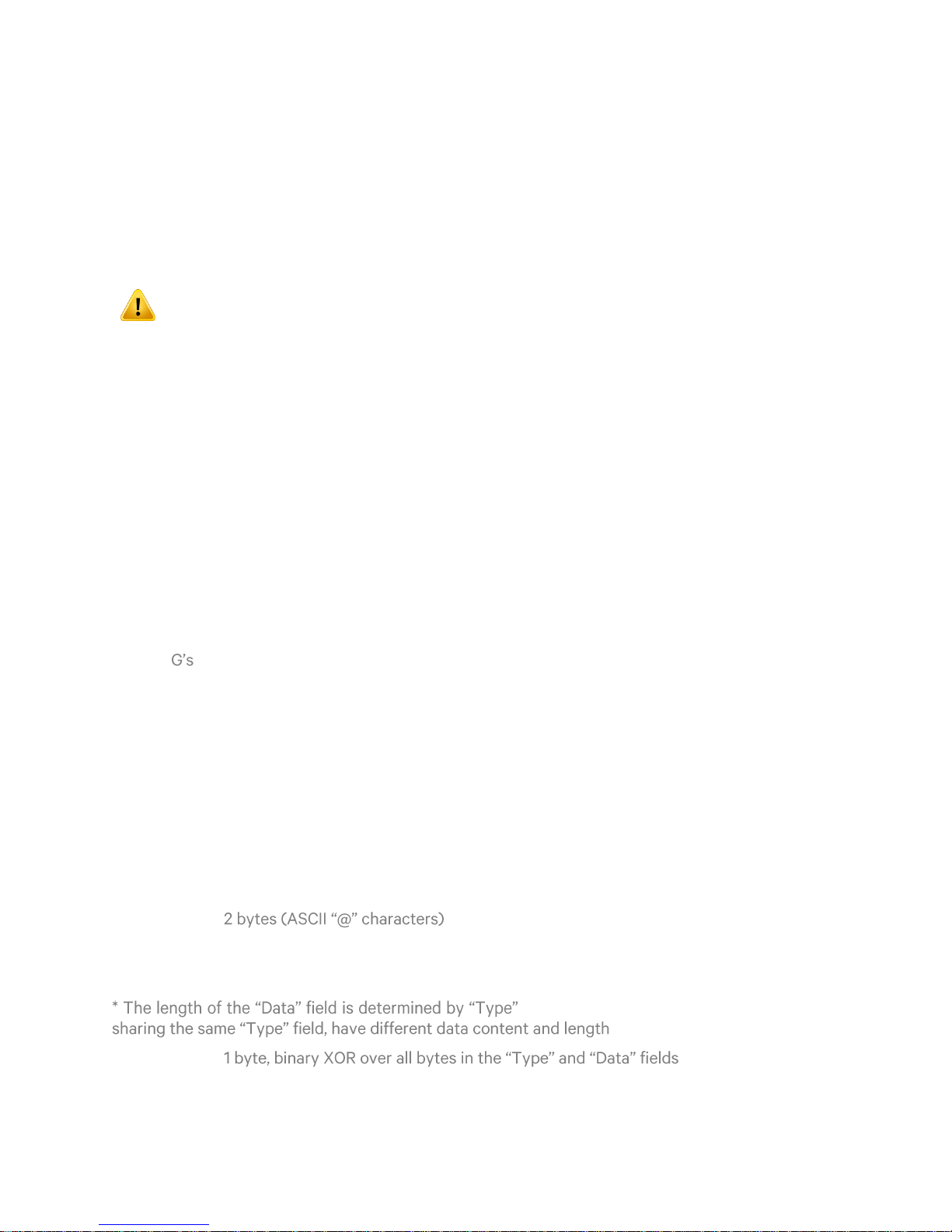
All command and response messages used by TCG 01-G have the same structure:Prefix:
Type: 2 bytes (ASCII alphabetic characters - case matters!)
Data: n* bytes (May be ASCII or binary data)
. Command and Response commands, while
.
Checksum:
TEK-TCG 01-G-Manual-v5-092016 P a g e | 17 www.tekron.com
© 2016 by Tekron International Limited. All Rights Reserved. All trademarks are the property of their respective holders. The
information in this document is provided for informational use only and is subject to change. For further information or support, go to
www.tekron.com.
Page 18

Suffix: 2 bytes (ASCII <CR><LF>)
Byte #
Description (Data bytes only, bytes 4-29 in received message)
4
Antenna feed fault [A] only if antenna line is short or open circuit *
5
No GNSS Solutions [T] only if no satellites are available for time calculations *
6
S/N level low [S] only if S/N level is abnormally low for more than an hour *
7
Oscillator Error High [X] only if Oscillator Control value is extreme *
8
Oscillator DAC out of range [H] or [L] only if Oscillator Control tending
towards extreme *
9
GNSS Fail [B] only if internal GNSS receiver sub-system not operating
properly *
10
Not implemented ASCII [space] always
11
Tracking Satellites [0-9] = # of satellites in time solution (see note 1 below)
12
Receiver Operating Mode [0-5] see note 2 below
13 15
Time Tag Queue Indicator [000-512, 999] # of tags in queue (999=overflow)
16 18
Outage Indicator [000-999] Hours since receiver was last locked to GNSS
signals. Becomes non-zero one hour after loss of lock. Resets to zero when lock
is re-acquired
19 20
Outage Indicator [00-59] Minutes since receiver was last locked to GNSS
signals. Becomes non-zero one minute after loss of lock. Resets to zero when
lock is re-acquired.
21
Oscillator Correction. Most significant 4 bits of 16-bit D/A converter used for
oscillator control. Range is ASCII [@] to [O] (hex 40 to hex 4F)
22
Oscillator Correction. More significant 6 bits of 16-bit D/A converter used for
oscillator control. Range is ASCII [@] to [del] (hex 40 to hex 7F)
TCG 01-G Commands related to Event Time Tagging
These commands and their responses contain ASCII characters only. A general serial
communications program can be used to explore the event recording command/retrieval functions
manually. Note that the TCG 01-G native serial protocol does not include station addressing. In a
network-connected system, the address of the Serial to Ethernet interface device can serve as the
station address. Tekron International can supply such devices if required.
Ps command: Get Status
The Ps command invokes a Ps response that contains the clock status which includes the number
of tags currently in the time-tag event buffer.
Command (7 bytes [0-6]): Transmitted format: @@Ps#<CR ><LF>
Response: (33 bytes [0-32]): Received format: @@Ps{26 data bytes}{cs}<CR><LF>
TEK-TCG 01-G-Manual-v5-092016 P a g e | 18 www.tekron.com
© 2016 by Tekron International Limited. All Rights Reserved. All trademarks are the property of their respective holders. The
information in this document is provided for informational use only and is subject to change. For further information or support, go to
www.tekron.com.
Page 19
Byte #
Description (Data bytes only, bytes 4-29 in received message)
23
Oscillator Correction. Least significant 6 bits of 16-bit D/A converter used for
oscillator control. Range is ASCII [@] to [del] (hex 40 to hex 7F)
23
Frequency Error. Local Oscillator frequency offset as compared with GNSS
received signal. In ASCII, ±00000-99999 referenced to 1E-12
Notes concerning the Ps command:
Byte #
Description (Data bytes only, bytes 4-6 in received message)
4 6
ASCII [000-512, 999] Number of time-tag entries in TCG 01-G queue before
reset.
Byte #
Description (Data bytes only, bytes 4-29 in received message)
4
Day of Year in ASCII, 001 to 366
7
Delimiter, ASCII [:] (hex 3A)
8 9
Hour of Day in ASCII, 00-23
10
Delimiter, ASCII [:] (hex 3A)
11 12
Minute of Hour in ASCII, 00-59
* An ASCII [space] is transmitted if there is no alarm condition present
1. The TCG 01-G can track up to 14 satellites simultaneously. The message limitation of 9 is to
retain compatibility with older equipment using this message format.
2. Mode = 1: Satellite search, 2D/3D fix.
Mode = 2: GNSS Automatic site survey.
Mode = 3: GNSS position hold (most accurate time)
Pc command: Clear Time-Tag Buffer
The Pc command invokes a Pc response that returns the number of time-tags that were in TCG 01-
event buffer when the Pc command was received. The event buffer is then cleared.
Command (7 bytes [0-6]): Transmitted format: @@Pc3<CR><LF>
Response (10 bytes [0-9]): Received format: @@Pc{3 data bytes}{cs}<CR><LF>
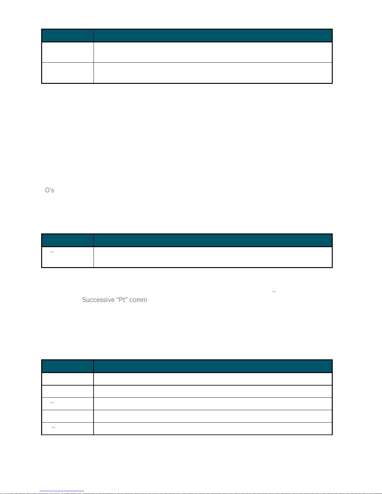
Pt command: Get next Time-Tag
The Pt command invokes a Pt response that contains a single time-tag record the oldest one in the
data queue. ands will result in successive time tag data being retrieved. If the
queue is empty, the Pt response is a null time tag. (ASCII [0] characters in all fields except
delimiters).
Command (7 bytes [0-6]): Transmitted format: @@Pt$<CR><LF>
Response (33 bytes [0-32]): Received format: @@Pt{26 data bytes}{cs}<CR><LF>
TEK-TCG 01-G-Manual-v5-092016 P a g e | 19 www.tekron.com
© 2016 by Tekron International Limited. All Rights Reserved. All trademarks are the property of their respective holders. The
information in this document is provided for informational use only and is subject to change. For further information or support, go to
www.tekron.com.
Page 20
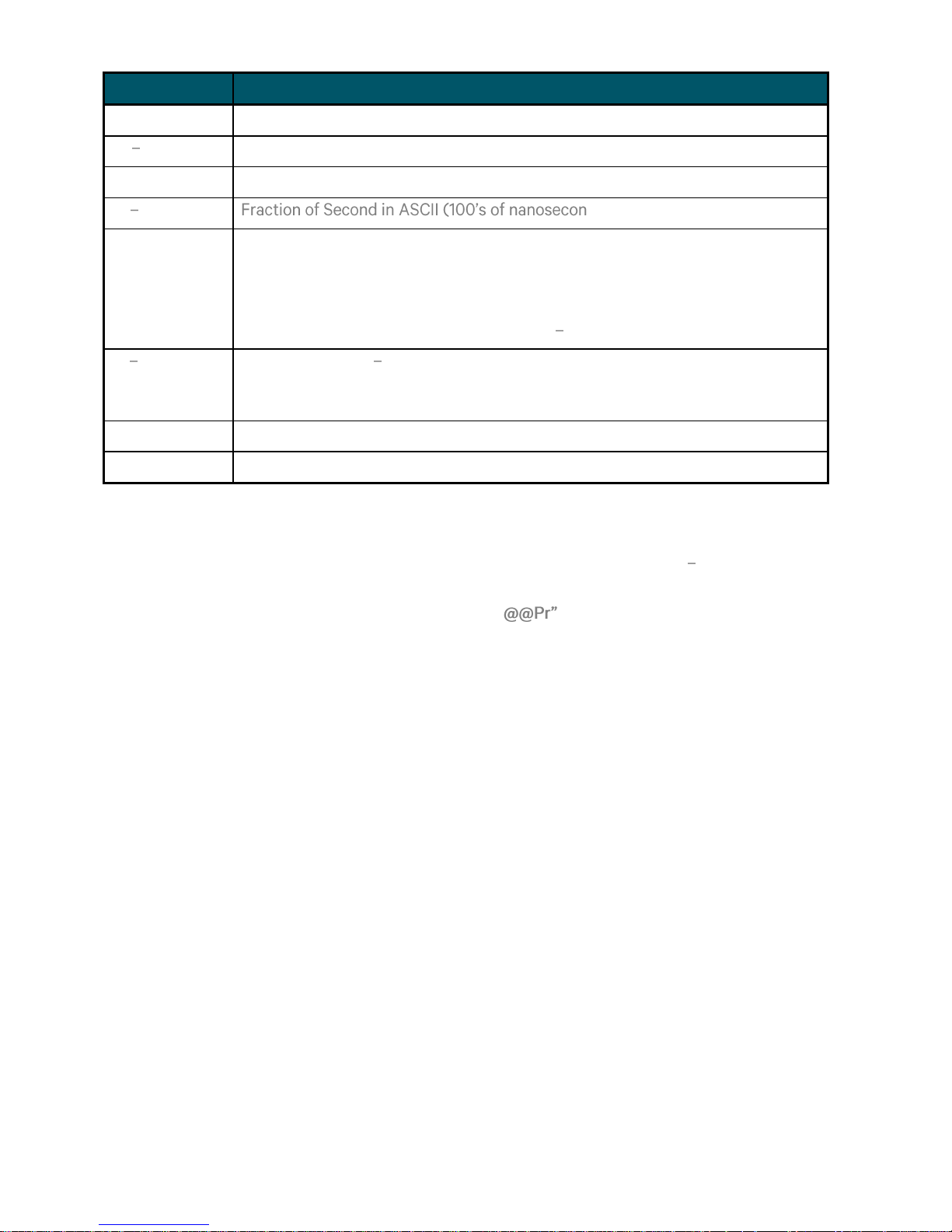
Byte #
Description (Data bytes only, bytes 4-29 in received message)
13
Delimiter, ASCII [:] (hex 3A)
14 15
Second of Minute in ASCII, 00-60
16
Delimiter, ASCII [.] (hex 2E)
17 23
ds), 0000000-9999999
24
Quality Indicator. Codes are:
ASCII [space] (hex 20) if receiver locked, sub-100 ns Output accuracy
ASCII [?] (hex 3F) if receiver unlocked for more than 1 minute
ASCII [*] (hex 2A) if receiver in alarm mode antenna fail
25 27
Outage Indicator [000-999] Hours since receiver was last locked to GNSS
signals. Becomes non-zero one hour after loss of lock. Resets to zero when lock
is re-acquired.
28
Delimiter, ASCII [#] (hex 23)
29
Number of Time-Tag Channel in ASCII, 1-2
Pr command: Repeat last Tag Sent
The Pr command invokes a Pr response that contains a single time-tag record the same data that
was sent in response to the last Pt command.
Command (7 bytes [0-6]): Transmitted format: <CR><LF>
Response (33 bytes [0-32]): Received format: @@Pr{26 data bytes}{cs}<CR><LF>
Data format is identical to Pt data format above
P6 Input Function (IRIG-B / Event Recording)
This feature provides a means to monitor /control signal activity on the two input channels of P6.
The TCG 01-G clock supports both IRIG-B and event input functions on the two P6 input lines
(Figure 10). If one IRIG-B input function and one Event input function are selected, then P6A should
be connected to the Event input source, and P6B connected to the IRIG-B signal source. As
described on Table 1b, when synced to IRIG-B, on the bottom right of the LCD will show SL1 or SL2 to
indicate synchronization with a source from P6A or P6b respectively.
TEK-TCG 01-G-Manual-v5-092016 P a g e | 20 www.tekron.com
© 2016 by Tekron International Limited. All Rights Reserved. All trademarks are the property of their respective holders. The
information in this document is provided for informational use only and is subject to change. For further information or support, go to
www.tekron.com.
Page 21
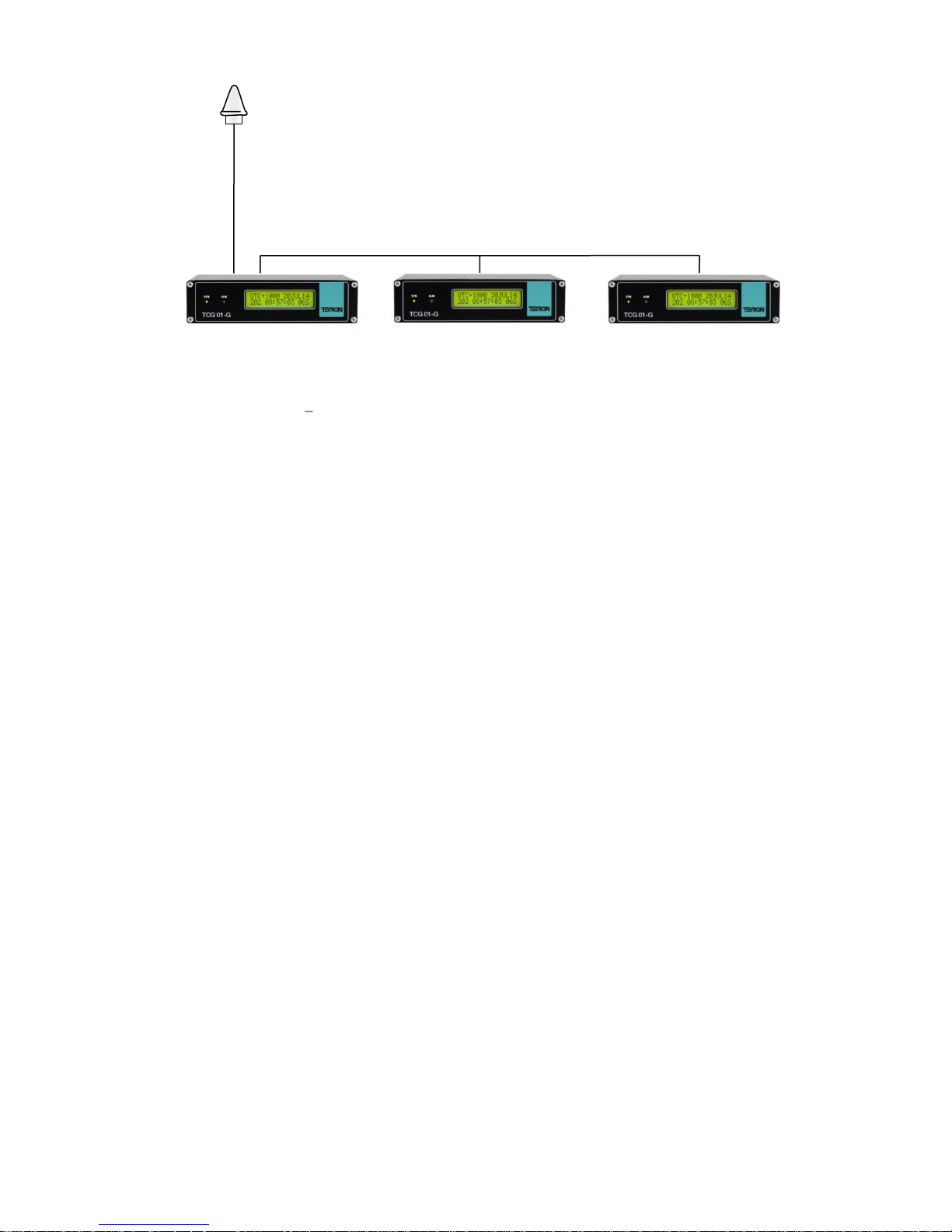
GNSS Antenna
P6 input [+1, C]
P6 input [+1, C]
TTL level IRIG-B with
IEEE extensions
(P2 or P3)
Master
Ant
Slave 1
Slave 2
Figure 10 Multiple Time Code Generators with one GNSS antenna
TEK-TCG 01-G-Manual-v5-092016 P a g e | 21 www.tekron.com
© 2016 by Tekron International Limited. All Rights Reserved. All trademarks are the property of their respective holders. The
information in this document is provided for informational use only and is subject to change. For further information or support, go to
www.tekron.com.
Page 22
6. FACTORY HARDWARE OPTIONS
Designator
DC Input Range
L (Low)
14 - 36 Vdc
M (Medium)
20 - 75 Vdc
H (High)
90 - 300 Vdc
LOAD
FUSE
+
300Vdc max
Positive earth system
+ P2 0
HV MOSFET
Power Supply Options
This table shows the three different power supply configurations that may be ordered with
TCG 01-G.
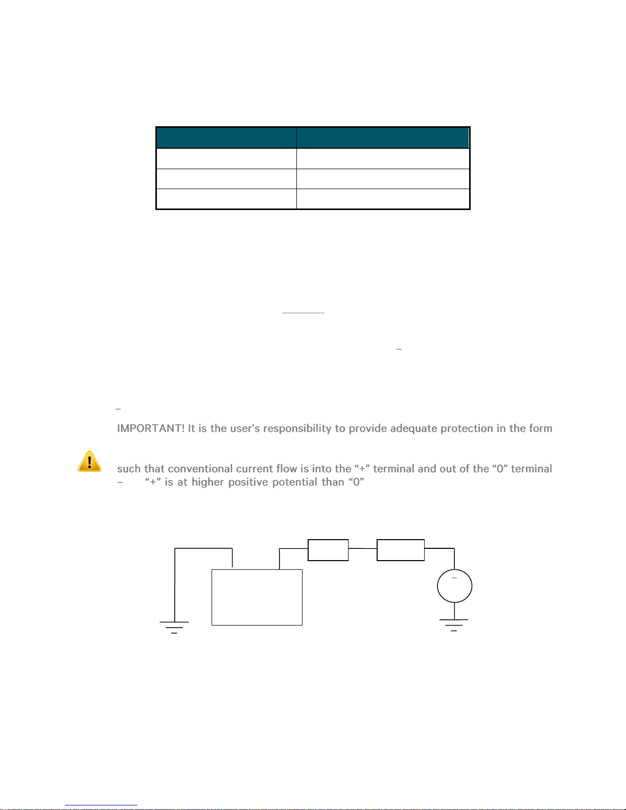
High Voltage (MOSFET) Output Option
TCG 01-G may be ordered with either or both of the P2 and P3 outputs configured with a high
voltage FET switching transistor instead of the standard 5 V logic output. When fitted in this
manner, each output can switch a 300 V DC, 1 A external load.
External wiring should be arranged so that the external high voltage supply line (up to 300 V DC
max) is connected, via a fuse, to the load (Figure 11). The return connection from the load is then
wired to one terminal of the P2 (P3) output, and the other terminal of the P2 (P3) output is then
wired to complete the circuit back to the other side of the power supply. Do not connect the high
voltage supply to P2 or P3 unless the high voltage option is fitted check the label on the base of
the TCG 01-G unit.
Output isolation (from chassis and other I/O) is still maintained when the HV option is fitted. This
simplifies the external load/supply arrangements, particularly when operating with positive-earth
systems as in many utility facilities.
of an external fuse to protect the external power supply, the TCG 01-G output switch
and the load. Note: At all times, the polarity of the P2 (P3) connections should be
i.e. . Failure to observe the polarity will
result in the output being permanently on, regardless of the state of the output.
TCG 01-G with
TEK-TCG 01-G-Manual-v5-092016 P a g e | 22 www.tekron.com
© 2016 by Tekron International Limited. All Rights Reserved. All trademarks are the property of their respective holders. The
information in this document is provided for informational use only and is subject to change. For further information or support, go to
www.tekron.com.
Page 23
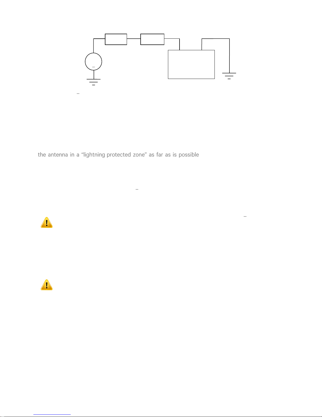
Negative earth system
+ P2 0
TCG 01-G with
HV MOSFET
LOAD
FUSE
+
300Vdc max
Figure 11 High voltage MOSFET output switch option: Suggested wiring arrangements
Lightning Protection Option
A lightning Protection kit may be fitted into the antenna lead-in cable. The kit contains a protection
device, two coaxial cable connectors, a connector crimp tool, and mounting hardware.
General
The first line of protection against the effects of lightning-induced surge events involves positioning
- . In practice, this means ensuring
that there is at least one other earth-bonded structure located in the same rooftop area (e.g. another
antenna, or a lightning rod) that reaches significantly higher than the top of the GNSS antenna. The
GNSS antenna should then be mounted so that it lies within a 45-degree angle from the top of the
other earth-bonded structure. The GNSS antenna mount itself should also be securely bonded
directly to the building protection earth and not connected via any of the other earthed structures.
However, this will not provide immunity from damage caused by a direct lightning strike, or voltages
induced in the antenna lead-in cable due to side flashes or induction.
All Tekron antenna installations should follow the guidelines above regardless of
whether a separate lightning protection device is to be fitted to the antenna lead-in
cable.
In areas with a low incidence of electrical storms, careful attention to antenna positioning and earth
connections may be all the protection deemed necessary. The antenna lightning protection kit LPK
01 affords additional security through the use of an impulse suppressor installed in the antenna leadin coax cable. In the event of a lightning-derived high voltage surge occurring on the coaxial cable,
the impulse suppressor activates, short-circuiting the cable directly to the protection ground.
While the Lightning Protector kit provides a high degree of protection, there is no
guarantee of protection against ALL surge related events, including a direct lightning
strike to the antenna. Careful antenna positioning is strongly advised!
The performance of the antenna system under normal (non-surge) conditions is unaffected by the
introduction of a correctly installed Lightning Protector.
Installation
The impulse suppressor should be installed as per the instructions provided with the impulse
suppressor.
TEK-TCG 01-G-Manual-v5-092016 P a g e | 23 www.tekron.com
© 2016 by Tekron International Limited. All Rights Reserved. All trademarks are the property of their respective holders. The
information in this document is provided for informational use only and is subject to change. For further information or support, go to
www.tekron.com.
Page 24

Disclaimer
TEKRON INTERNATIONAL disclaims any liability or responsibility for the results of improper or
unsafe installation practice including, but not limited to, any excessive performance degradation of
the antenna system resulting from incorrect field installation of coaxial cable connectors.
TEK-TCG 01-G-Manual-v5-092016 P a g e | 24 www.tekron.com
© 2016 by Tekron International Limited. All Rights Reserved. All trademarks are the property of their respective holders. The
information in this document is provided for informational use only and is subject to change. For further information or support, go to
www.tekron.com.
Page 25

7. APPENDIX
Performance Property
Metric
Dimensions
Width
160 mm
Depth
155 mm
Height
40 mm
Weight
800 g
L1/GLONASS (1575.42 / 1598 MHz) Frequency, C/A Code, 32 Channel, parallel-tracking
receiver
Performance Property
Metric
Position Accuracy
Horizontal
<9 m (90%)
Altitude
<18 m (90%)
Timing Accuracy
15 ns (1 sigma) to UTC
Acquisition
Reacquisition
<2 s (90%)
Hot Start
<18 s (90%)
Warm Start
<45 s (90%)
Cold Start
<50 s (90%)
Sensitivity
Acquisition
-155 dBm
Tracking
-160 dBm
Type
Electrical
Physical
Accuracy at the port
AM IRIG-B (modulated)
8 V
p-p
BNC
<2 µs of UTC
TTL
5 V
2 pin Phoenix or BNC
<100 ns of UTC
RS422/485
2 pin Phoenix or BNC
<100 ns of UTC
RS232/RS422 (Pulse)
DB9
<1.5 µs of UTC
RS232/RS422 (String)
DB9
Baud rate dependent
HV Switching
(MOSFET)
2 pin Phoenix
<100 ns of UTC
Fiber (λ=820 nm)
N/A
ST
<100 ns of UTC
TCG 01-G Specifications
Physical Specifications
GNSS Receiver
Input and Output Specifications
TEK-TCG 01-G-Manual-v5-092016 P a g e | 25 www.tekron.com
© 2016 by Tekron International Limited. All Rights Reserved. All trademarks are the property of their respective holders. The
information in this document is provided for informational use only and is subject to change. For further information or support, go to
www.tekron.com.
Page 26

Type
Electrical
Physical
Accuracy at the port
NTP / SNTP/PTP
RJ45
<100 ns of UTC
Environmental Specifications
Performance Property
Metric
Operating Temperature Range
-10 ~ +65 °C
Performance Property
Metric
Power Supply
Low Voltage
14 ~ 36 Vdc
Medium Voltage
20 ~ 75 Vdc
High Voltage
90 ~ 300 Vdc
Power drain
6 W max
Electrical Specifications
TEK-TCG 01-G-Manual-v5-092016 P a g e | 26 www.tekron.com
© 2016 by Tekron International Limited. All Rights Reserved. All trademarks are the property of their respective holders. The
information in this document is provided for informational use only and is subject to change. For further information or support, go to
www.tekron.com.
Page 27
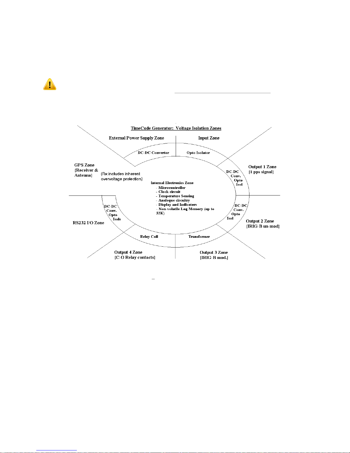
ISOLATION & PROTECTION
All inputs and outputs feature 2.5 kV isolation from earth and 5 kV isolation from each other. In
addition, the logic level outputs (P2 and P3) are each protected against damage from transverse
voltage events via a three-stage network of varistor, auto-resetting fuse, and transient suppressor
diode.
Fuse and varistor protection is removed when the switching MOSFET factory option
is fitted. The user must provide an external power supply and suitable fusing to use
the MOSFET output option (see FACTORY HARDWARE OPTIONS for further
information).
Varistor protection and current limiting (nominally 5 mA) are employed for protection on the
general-purpose input.
Figure 12 TCG 01-G isolation zones
Transformer isolation via DC-DC converter is used for the main power supply and for power to each
of the logic output-drive circuits. The serial communications interface is also separately powered via
isolating DC-DC converter. High-speed, fixed delay opto-isolators are used in each of the timesensitive signaling paths. The isolation does not degrade the time accuracy of the output signals, as
the fixed delays of the isolating components (together with the delay associated with the antenna
lead-in) are all internally compensated.
TEK-TCG 01-G-Manual-v5-092016 P a g e | 27 www.tekron.com
© 2016 by Tekron International Limited. All Rights Reserved. All trademarks are the property of their respective holders. The
information in this document is provided for informational use only and is subject to change. For further information or support, go to
www.tekron.com.
Page 28

SERIAL OUTPUT STRINGS
About
Normally used in conjunction with 10 ms pulse on P4 pin 1 that finishes
precisely on the minute.
Timing
Transmitted once per minute. Sent during the last second before the minute
rollover to which the data in the string refers.
Comms
9600bps, 8-bit ASCII, no parity
Definition
TyyMMDDwhhmmx<CR><LF>
Placeholder
Content
T
ASCII "T"
yy
Last two digits of the year: e.g.
MM
DD w
hh
Two digit hour
mm
Two digit minute
x
<CR><LF>
Carriage Return Line Feed Pair: HEX 0D 0A
About
This code is compatible with IRIG Standard 212-00.
Timing
Transmitted once every second. T
character <SOH> is exactly on the second that the message describes.
Comms
9600bps, 7-bit ASCII, odd parity
Definition
<SOH>ddd:hh:mm:ss<CR><LF>
Placeholder
Content
<SOH>
Start of Header: HEX 01
ddd
:
HEX 3A
NGTS Time Code O/P on P4
Example Interpretation
T020422112340<CR><LF> Monday 22 April 2002 12:34 local time
IRIG J-17 Time Code O/P on P4
TEK-TCG 01-G-Manual-v5-092016 P a g e | 28 www.tekron.com
© 2016 by Tekron International Limited. All Rights Reserved. All trademarks are the property of their respective holders. The
information in this document is provided for informational use only and is subject to change. For further information or support, go to
www.tekron.com.
Page 29

Placeholder
Content
hh
mm
ss
<CR><LF>
Carriage Return Line Feed Pair: HEX 0D 0A
Example Interpretation
About
This code is very similar in data content to the IRIG J-17 code, but adds a twocharacter field containing the year, and uses 8-bit ASCII, no parity data format.
Timing
Transmitted once every second. The leading edge of
character <SOH> is exactly on the second that the message describes.
Comms
9600bps, 8-bit ASCII, no parity
Definition
<SOH>ddd:hh:mm:ss:yy<CR><LF>
Placeholder
Content
<SOH>
Start of Header: HEX 01
ddd
:
HEX 3A
hh
mm
ss
yy
<CR><LF>
Carriage Return Line Feed Pair: HEX 0D 0A
About
otherwise is identical in form, function and timing to String-A.
Timing
Transmitted once every second. T
character <SOH> is exactly on the second that the message describes.
<SOH>112:12:34:36<CR><LF> day 112, time 12:34:36
String-A Time Code O/P on P4
Example Interpretation
<SOH>112:12:34:36:10<CR><LF> day 112, time 12:34:36, year (20)10
String-B Time Code O/P on P4
TEK-TCG 01-G-Manual-v5-092016 P a g e | 29 www.tekron.com
© 2016 by Tekron International Limited. All Rights Reserved. All trademarks are the property of their respective holders. The
information in this document is provided for informational use only and is subject to change. For further information or support, go to
www.tekron.com.
Page 30

Comms
9600bps, 8-bit ASCII, no parity
Definition
<SOH> DDD:hh:mm:ssQ<CR><LF>
Refer to String-A table (above) for the definitions of the common digits
Meaning
HEX
ASCII
20
pace)
Clock in sync, timing accuracy is better than 60 ns
2E
. (full stop)
Clock is accurate to 1 µs
2A
*
Clock is accurate to 10 µs
23
#
Clock is accurate to 100 µs
3F
?
Clock accuracy may be worse than 100 µs
About
This code is effectively a combination of String-A and String B. It provides
both year information and a sync indicator field.
Timing
Transmitted once every second. T
character, <CR>, is exactly on the second to which the message data refers.
Comms
9600bps, 8-bit ASCII, no parity
Definition
<CR><LF>Q yy ddd hh mm ss.000
Placeholder
Content
<CR><LF>
Carriage Return Line Feed Pair: HEX 0D 0A
Q
Quality indicator: = in- -of-sync
HEX 20 (space)
yy
nting the last two digits of the year
HEX 20 (space)
ddd
HEX 20 (space)
hh
mm
Example Interpretation
<SOH>112:12:34:36?<CR><LF> day 112, time: 12:34:36, >100 µs sync error
String-C Time Code O/P on P4
TEK-TCG 01-G-Manual-v5-092016 P a g e | 30 www.tekron.com
© 2016 by Tekron International Limited. All Rights Reserved. All trademarks are the property of their respective holders. The
information in this document is provided for informational use only and is subject to change. For further information or support, go to
www.tekron.com.
Page 31

Placeholder
Content
ss
.000
.
HEX 20 (space)
HEX 20 (space)
HEX 20 (space)
Example Interpretation
About
This provides time, year information, and a sync indicator field.
Timing
The string is transmitted once every second, with the leading edge of the
.
Comms
9600bps, 8-bit ASCII, no parity
Definition
<SOH>YYYY:ddd:hh:mm:ssQ<CR><LF>
Placeholder
Content
<SOH>
Start of Header: HEX 01
YYYY
4-digit year
:
HEX 3A
ddd
Day
hh
mm
ss
Q
Quality character, as defined in String-B (above)
<CR><LF>
Carriage Return Line Feed Pair: HEX 0D 0A
<CR><LF>? 02 112 12:34:36.000 day 112 of year (20)02, time: 12:34:36, out-of-sync
String-D Time Code O/P on P4
String-D is IDENTICAL in content to String-B, but the second mark is at the leading edge of the
start-bit of the (<CR>).
Example Interpretation
<SOH>112:12:34:36?<CR><LF> day 112, time: 12:34:36, >100 µs sync error
String-E Time Code O/P on P4
TEK-TCG 01-G-Manual-v5-092016 P a g e | 31 www.tekron.com
© 2016 by Tekron International Limited. All Rights Reserved. All trademarks are the property of their respective holders. The
information in this document is provided for informational use only and is subject to change. For further information or support, go to
www.tekron.com.
Page 32
Example Interpretation
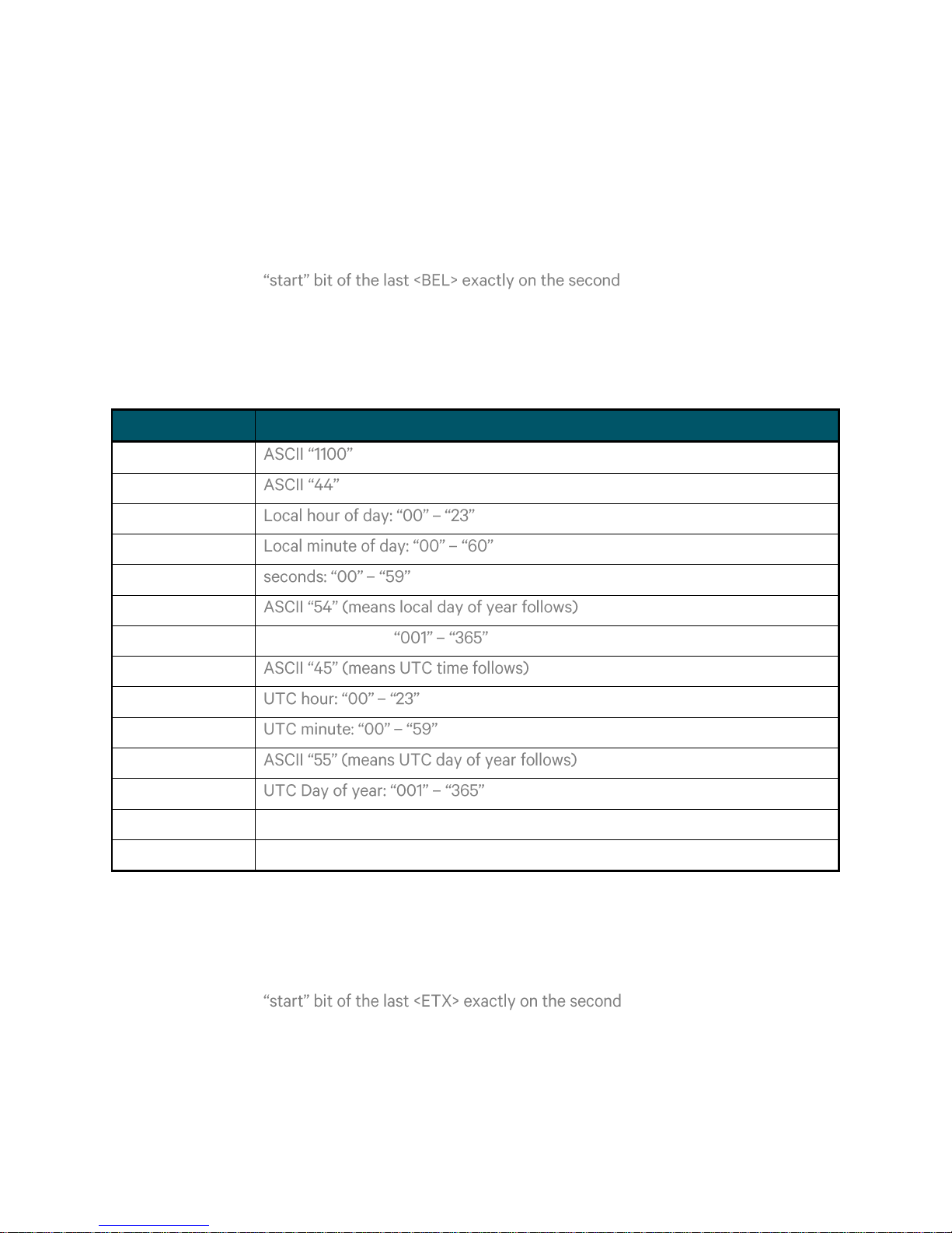
About
This string complies with the protocol required to drive Vorne type Time
Displays.
Timing
The string is transmitted once every second, with the leading edge of the
.
Comms
9600bps, 8-bit ASCII, no parity
Definition
<CR><LF>1100<CR><LF>44hhmmss<CR><LF>54ddd<CR><LF>
<CR><LF>45HHMMss<CR><LF>55DDD<CR><LF><BEL>
Placeholder
Content
1100
44
(means local time follows)
hh
mm
ss
54
ddd
Local day of year:
45 HH
MM
55 DDD
<BEL>
HEX 07
<CR><LF>
Carriage Return Line Feed Pair: HEX 0D 0A
About
This general time string is used predominantly in Europe.
Timing
The string is transmitted once every second, with the leading edge of the
.
Comms
9600bps, 8-bit ASCII, no parity
Definition
<STX>swhhmmssddMMyy<LF><CR> <ETX>
<SOH>2004:112:12:34:36?<CR><LF> 2004, day 112, 12:34:36pm, >100us sync error
String-F Time Code O/P on P4
String-G Time Code O/P on P4
TEK-TCG 01-G-Manual-v5-092016 P a g e | 32 www.tekron.com
© 2016 by Tekron International Limited. All Rights Reserved. All trademarks are the property of their respective holders. The
information in this document is provided for informational use only and is subject to change. For further information or support, go to
www.tekron.com.
Page 33
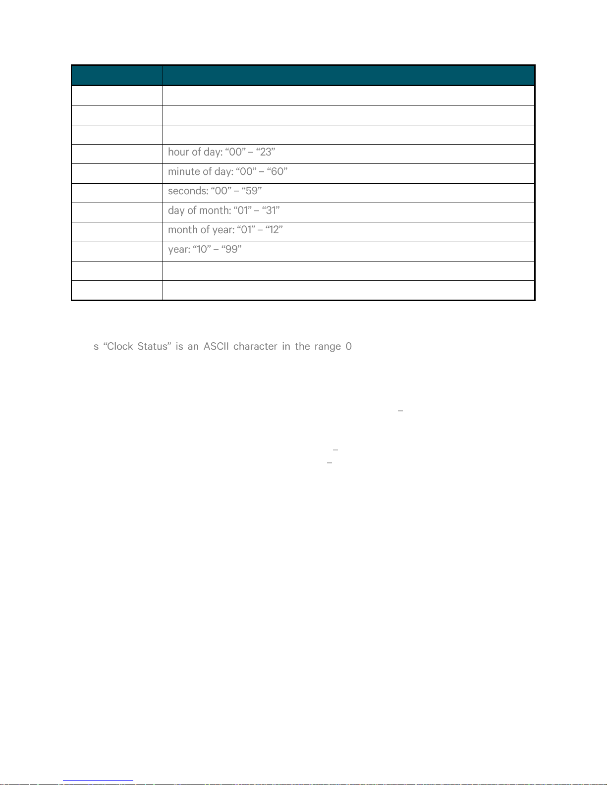
Placeholder
Content
<STX>
Start of Text: HEX 02
s
Clock Status (see below)
w
Day of Week (see below)
hh
mm
ss
dd
MM
yy
<CR><LF>
Carriage Return Line Feed Pair: HEX 0D 0A
<ETX>
End of Text: HEX 03
CLOCK STATUS
The -9, A-F representing a single hex digit
(nibble)
Bits: 3 2 1 0
X X X 0 No announcement for time change
X X X 1 Announcement for time change active for an hour before
X X 0 X Local Standard Time (LST)
X X 1 X Daylight Saving Time (DST)
0 0 X X Time/date invalid clock is out of sync
0 1 X X Hold-over mode running on local Oscillator
1 0 X X GNSS / IRIGB controlled mode
1 1 X X GNSS / IRIGB controlled mode (high accuracy)
TEK-TCG 01-G-Manual-v5-092016 P a g e | 33 www.tekron.com
© 2016 by Tekron International Limited. All Rights Reserved. All trademarks are the property of their respective holders. The
information in this document is provided for informational use only and is subject to change. For further information or support, go to
www.tekron.com.
Page 34
DAY OF WEEK
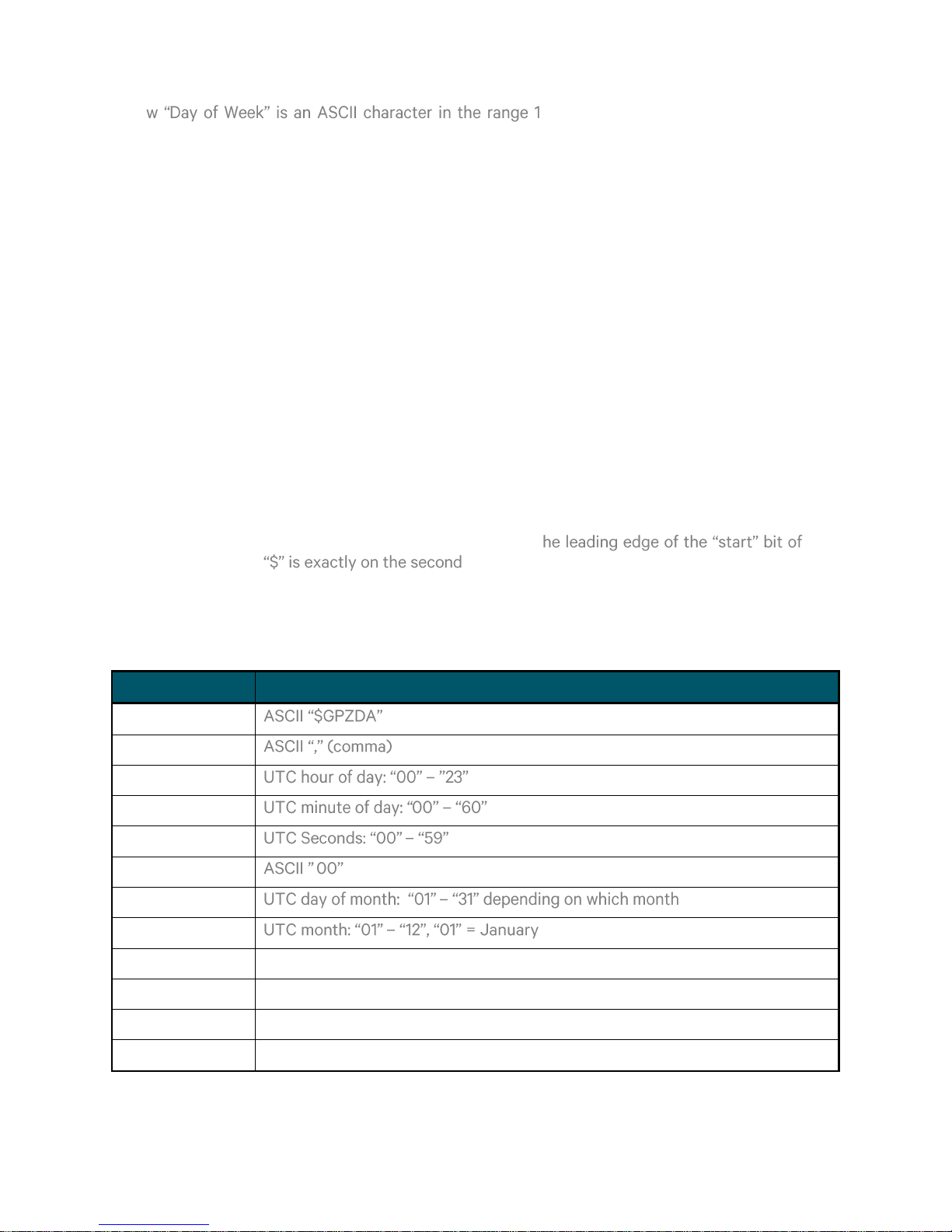
About
This string is in accordance with the NMEA-0183 standard in content, but is
transmitted at 9600bps.
Timing
Transmission is once every second. T the
.
Comms
9600bps, 8-bit ASCII, no parity
Definition
$GPZDA,hhmmss.00,dd,mm,yyyy,s,xx,yy*CC<CR><LF>
Placeholder
Content
$GPZDA
, hh
mm
ss
.00
.
dd
mm
yyyy
UTC year, 4 digits.
s
Local time zone offset sign (positive means local time leads UTC)
xx
Local time zone offset from UTC in hours
yy
Local time zone offset from UTC in minutes
The -7, 9, A-F representing a single hex digit
(nibble)
Bits: 3 2 1 0
1 X X X UTC time
X 0 0 1 Monday
X 0 1 0 Tuesday
X 0 1 1 Wednesday
X 1 0 0 Thursday
X 1 0 1 Friday
X 1 1 0 Saturday
X 1 1 1 Sunday
Example Interpretation
<STX>E3123456170410<LF><CR><ETX> High Accuracy Mode, DST, Wed, 12:34:56, 17/4/2010
NMEA ZDA Time Code O/P on P4
TEK-TCG 01-G-Manual-v5-092016 P a g e | 34 www.tekron.com
© 2016 by Tekron International Limited. All Rights Reserved. All trademarks are the property of their respective holders. The
information in this document is provided for informational use only and is subject to change. For further information or support, go to
www.tekron.com.
Page 35
Placeholder
Content
*
CC
2-digit hex representation of the result of XORing the 8 data bits of each
character between, but not including the "$" and "*".(00-FF)
<CR><LF>
Carriage Return Line Feed Pair: HEX 0D 0A
Example Interpretation
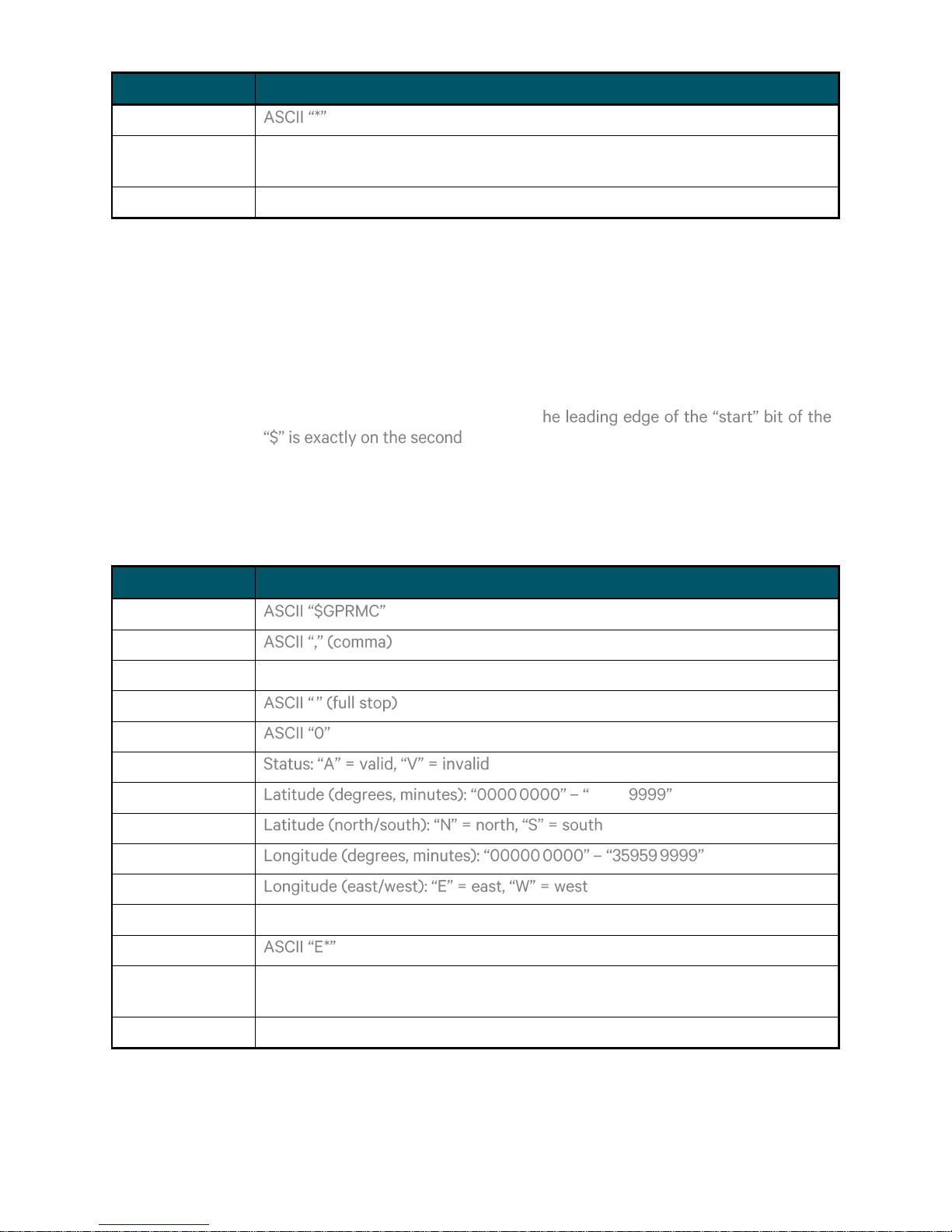
About
This string is compatible with and defined by the NMEA-0183 standard.
Timing
Transmission is once every second. T
.
Comms
9600bps, 8-bit ASCII, no parity
Definition
$GPRMC,hhmmss.00,a,tttt.tttt,N,ggggg.gggg,W,0.0,0.0,DDMMYY,0.0,E
*CC<CR><LF>
Placeholder
Content
$GPZDA
,
hhmmss
UTC hour of day, minute of day, seconds
.
.
0
a tttt.tttt
. 8959.
N
ggggg,gggg
. .
W
ddmmyy
UTC day of month, month, 2-digit year:
E*
CC
2-digit hex representation of the result of XORing the 8 data bits of each
character between, but not including the "$" and "*".
<CR><LF>
Carriage Return Line Feed Pair: HEX 0D 0A
$GPZDA,123456.0023042010+1200* UTC time is 12:34:56, 23 April 2010, the local time
offset is +12:00
NMEA RMC Time Code O/P on P4
TEK-TCG 01-G-Manual-v5-092016 P a g e | 35 www.tekron.com
© 2016 by Tekron International Limited. All Rights Reserved. All trademarks are the property of their respective holders. The
information in this document is provided for informational use only and is subject to change. For further information or support, go to
www.tekron.com.
Page 36

8. WARRANTY
Warranty see the Web Site
http://tekron.com/about-tekron/warranty
WARNING
This product has been designed to comply with the limits for a Class A digital device pursuant to
Part 15 of FCC rules. These limits are designed to provide reasonable protection against such
interference when operating in a commercial environment.
Notes
Ethernet is a trademark of XEROX Corporation. Windows, Windows 95, Windows 98, Windows 2000,
Windows NT, Windows XP, Windows Vista and Window
TEK-TCG 01-G-Manual-v5-092016 P a g e | 36 www.tekron.com
© 2016 by Tekron International Limited. All Rights Reserved. All trademarks are the property of their respective holders. The
information in this document is provided for informational use only and is subject to change. For further information or support, go to
www.tekron.com.
 Loading...