

Page 1
Quick Start Guide
Tek-Flex 4100C
Programmable Two-wire TDR Level Transmitter With Hart & Display
796 Tek Drive, Crystal Lake, IL 60014 USA
+1 847 857 6076 |+1 847 655 7428 +1 847 655 6147
www.tek-trol.com
Page 2

Quick Start Guide
Quick Start Guide
1. Before You Begin
This guide provides basic guidelines to assist you in quickly getting started. Go to our website to download the
full User Guide for detailed installation, maintenance, troubleshooting and safety precautions.
The user must take note of the safety instructions in this operating instructions manual, the country
specic installation standards as well as all prevailing safety regulations and accident prevention rules.
The instrument must only be operated in a technically awless and reliable condition. The operator is
responsible for trouble-free operation of the instrument. During the entire duration of use, the user is
obliged to determine the compliance of the required occupational safety measures with the current valid
rules and regulations and also take note of new regulations.
2. Unpack
One Tek-Flex 4100C Programmable Two-wire TDR Level Transmitter With Hart & Display
3. Dimensional Drawing
3.84"
(0.32 ft)
0.94"
0.86"
5.37"
(0.44 ft)
1½ NPT
2.6"
3 ft. to 60 ft.
796 Tek Drive, Crystal Lake, IL 60014 USA
+1 847 857 6076 |+1 847 655 7428 +1 847 655 6147
5.91"
www.tek-trol.com
Page 3
Technology Solutions
4. Mounting Requirement
Basic Requirement for Installation
Keep in mind that the cable/rod is kept away from obstructions within vessel. The obstructions like: ladders,
limit switches, heating spirals, struts and etc. Further more, rope or rods must not intersect the lling
streams.
Be cautious during the installation: the level of the measured cable medium must not be in the blanking
zone the mounting location must keep a min distance to the vessel wall, the cable or rod is perpendicular to
the surface of the measured medium.
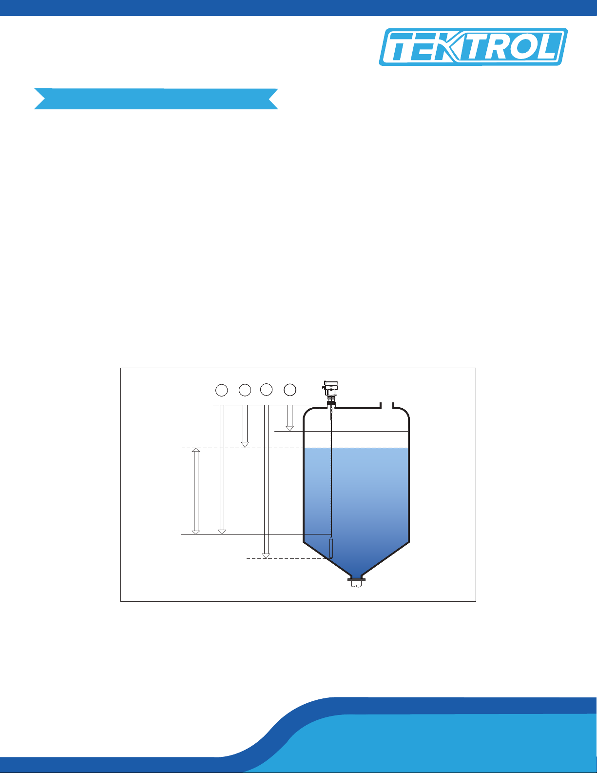
Illustration
The reference plane is the thread or ange surface
1 Blanking Zone
2 Length
3 Max. Measurement Range
4 Min. Measurement Range
5 Reference plane
2
4
3
5
100%
0%
Note: The level of the measured medium must not be in either the blanking zone.
The best mounting location for a conical vessel with at top is the centre of the vessel's top, as the eective
measurement can reach the bottom of vessel.
1
Tek-Bar 3100
Tek-Flex 4100C
Page 4

Quick Start Guide
Quick Start Guide
Stand Pipe
Avoid installation with socket if possible, otherwise try to minimize the length of socket. In case of long
stand pipe, small vessel or medium with low dielectric constant.
h
d
Mounting
1 Wrong: The rod/rope is in/above lling stream, which results in the measurement of lling stream not the
target medium.
2 Correct
Note: Sun shield or rain-proof is suggested for outdoor mounting.
1
2
796 Tek Drive, Crystal Lake, IL 60014 USA
+1 847 857 6076 |+1 847 655 7428 +1 847 655 6147
www.tek-trol.com
Page 5

Technology Solutions
Horizontal and Vertical Installation
When mounting outdoors, humid indoors or on cooling/heating vessels, in order to avoid damp seal rings
used on cables should be screwed tight, and the cable must be bended downward outside cable entry, as
indicated on the diagram below:
5. Power Supply
Power supply and current signal are carried by the same two-wire connection cable. See the Technical Specications of this guide for detailed requirement on power supply.
++-
1
2
1
-
2 Wire
Tek-Bar 3100
Tek-Flex 4100C
Page 6

Quick Start Guide
Quick Start Guide
6. Adjustment Instructions
Use the operation panel of the transmitter to set the conguration parameters such as the zero calibration,
cut-o value of low ow and output range of current frequency, etc.
Display/Adjustment Module
dB
120
110
100
90
80
70
60
50
40
30
20
10
0
0.00
2.00 3.00 4.0 0 5.00
LCD
[OK] Keypad
•
Enter programming mode
•
Conrm programming options
•
Conrm modications to parameters
[ ] Keypad
•
Modify parameter values
Connect with Another Unit Through HART
2 Adjustment Keypad
[ ] Keypad
•
Choose programming options
•
Choose the digit of parameters to edit
•
Display the contents of parameters
[ BK ] Keypad
•
Programming mode exit
•
Return to higher menu level
HART to USB Modem
4100C
796 Tek Drive, Crystal Lake, IL 60014 USA
250 ohm
Resistance
+1 847 857 6076 |+1 847 655 7428 +1 847 655 6147
www.tek-trol.com
Page 7

HART Handheld Programmer
Adjust 4100C with HART Handheld Programmer
4100C
7. Menu Tree
250 ohm
Resistance
HART Handheld
Programmer
+
- DC
Technology Solutions
Basic Setting
Display 2
Diagnostics 3
Service 4
Info 5
Min adjustment
1.1
Min adjustment
1.2
Medium 1.3
Fast level change
1.4
Damping 1.5
Mapping curve
1.6
Scaled units 1.7
Scaling 1.8
Sensor length
1.9
Linearity consumer
programme 1.5
Near blanking
1.10
Tek-Bar 3100
Tek-Flex 4100C
Sensor tag
1.11
Page 8

Quick Start Guide
Quick Start Guide
Basic Setting
Display 2
Diagnostics 3
Service 4
Info 5
Display value 2.1
LCD contrast 2.2
Peak values 3.1
Meas status 3.2
Choose curve 3.3
Echo curve 3.4
Simulation 3.5
Echo curve 4.1
Shut o map percent
distance scaled height
current percent
Distance- min
Distance- max
Meas reliability
sensor status
Echo curve false echo
curve output trend
Curve zoom
Percent
Current
Distance
Delete
Update
Create new
X- zoom
Y- zoom
Unzoom
1X
2X
5X
10X
Current output
4.2
Reset 4.13
Units of
measurement 4.4
Language 4.5
HART operation
mode 4.6
Copy sensor
Data 4.7
PIN 4.8
Sensor type
serial number
5.1
Output mode
Failure mode
Min current
Select reset
M (d)
ft (d)
Chinese
English
Standard
Multidrop
Copy from sensor
Copy to sensor
Basic reset
Factory settings
Peak values
Date of manufacture
software version 5.2
796 Tek Drive, Crystal Lake, IL 60014 USA
+1 847 857 6076 |+1 847 655 7428 +1 847 655 6147
www.tek-trol.com
Page 9

Technology Solutions
796 Tek Drive
Crystal Lake, IL 60014
USA
Tel: +1 847 857 6076, +1 847 655 7428
Fax : +1 847 655 6147
Email: tektrol@tek-trol.com
www.tek-trol.com
Tek-Flex 4100C
 Loading...