How it Works
Log In / Sign Up
Buy Points
How it Works
FAQ
Contact Us
Questions and Suggestions
Users
TekTone Sound and Signal Mfg
Loading...
P
PM550
Loading...
Loading...
Nothing found
PM550
User Manual
51 pgs
986.51 Kb
0
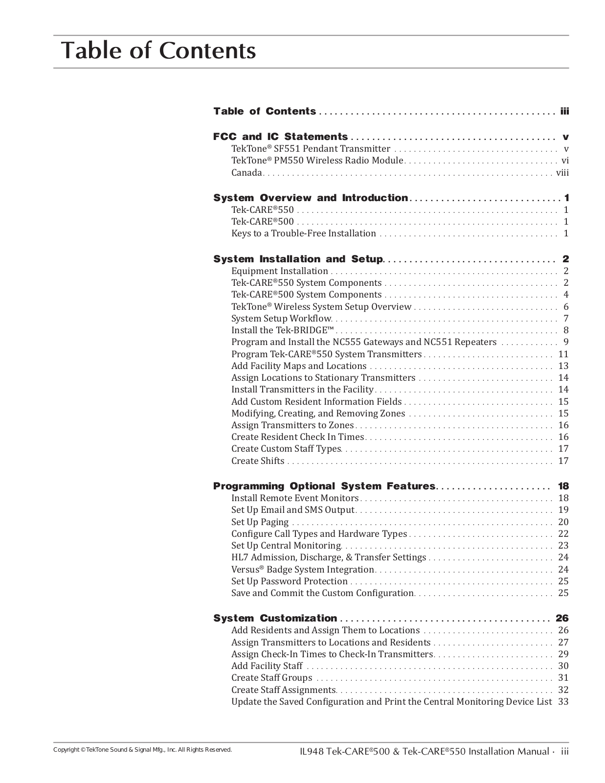
Table of contents
Loading...
TekTone Sound and Signal Mfg PM550 User Manual
...
TekTone Sound and Signal Mfg User Manual
Download
Specifications and Main Features
Frequently Asked Questions
User Manual
Download
Loading...
+
hidden pages
Unhide
You need points to download manuals.
1 point = 1 manual.
You can buy points or you can get point for every manual you upload.
Buy points
Upload your manuals