

TekTone Tek-SELECT II SM401, Tek-SELECT II SM404, Tek-SELECT II SM411, Tek-SELECT II SM406 Operation, Installation And Service Manual
Page 1

IL603
Section B
Rev. 5- 09/2001
Tek-SELECT®II
SM400 Series Multi-Master and Master/Remote
Intercom Systems
Website:
www.tektone.net
Email:
For Technical Assistance:
1-800-332-6608
Technical Assistance Email:
277 Industrial Park Road
Franklin, NC 28734
(828) 524-9967
(800) 327-8466
Fax (828) 524-9968
4190 Fairview St., Unit B-8
Burlington, ON L7L 4Y8
Canada
(905) 333-0051
Fax (905) 333-0599
Operation, Installation and Service Manual
APPLICATION: The SM401, SM404, SM406 and SM411 Tek-SELECT® II
Intercoms provide for master-to-master, master-to-remote and intermixed operation
suitable for offices, homes, warehouses and any areas where quick, convenient
loudspeaking communication is needed. Multicolored signal lights, hands-free reply,
privacy and monitoring are all standard features. Optional equipment is available
to call all stations, distribute music, and control remote devices.
Page 2

Copyright © 2001 T ekTone® Sound & Signal Mfg., Inc., All rights reserved.
The content of this manual is furnished for informational use only , is subject to change without notice, and
should not be construed as a commitment by T ekT one® Sound & Signal Mfg., Inc. T ekT one® Sound &
Signal Mfg., Inc. assumes no responsibility or liability for any errors or inaccuracies that may appear in this
documentation.
T ekT one, the T ekT one logo, T ek-Call, T ek-Care, T ek-Check-In, Tek-Com, T ek-Digicare, T ek-Door,
T ek-Entry III, T ek-Guard, T ek-Micro, T ek-MMARS II, T ek-NIOS, T ek-Paging, Tek-Phone, T ek-Safe,
T ek-Select II, T ek-Sentry, T ek-Sound, T ek-Status and Tek-View are either registered trademarks or
trademarks of T ekTone® Sound & Signal Mfg., Inc. in the United States and/or other countries. All other
trademarks are the property of their respective owners.
TekTone® Sound & Signal Mfg., Inc., 277 Industrial Park Road, Franklin, North Carolina 28734, USA.
Page ii • IL603 T ek-SELECT®II Manual
Page 3

TABLE OF CONTENTS
1.0 SYSTEM INSTALLATION
1.1 Installation Procedure ..................................................................... 1
1.2 Planning and Equipment Location ................................................... 1
Masters and Remotes .............................................................. 1
Power Supply and Relays ........................................................ 1
Transformer ............................................................................. 1
Music System ........................................................................... 1
1.3 System Housings............................................................................. 1
1.4 Wiring Installation ........................................................................... 1
Master Stations......................................................................... 1
All Call...................................................................................... 1
Background Music ................................................................... 2
Door Release ............................................................................ 2
Remote to Master Cable .......................................................... 2
Paging Horn ............................................................................. 2
1.5 Connections..................................................................................... 2
1.6 Equipment Installation ..................................................................... 2
Surface Mounting SM404, SM406 and SM411 Masters.......... 2
Flush Mounting SM404, SM406 and SM411 Masters.............. 2
Name Directory for SM404, SM406 and SM411 Masters ...... 2
SM401 Master and Remote Stations........................................ 2
SM404, SM406 and SM411 Masters ....................................... 2
1.7 SM400 Series Installation Instructions ............................................ 2
1.8 Factory Dip Switch Settings ........................................................... 3
Call Tone Volume Adjustment ................................................. 3
1.9 Terminal Reference for Master...................................................... 3
2.0 OPERATING INSTRUCTIONS
2.1 Master Station................................................................................. 5
Call another station ................................................................... 5
Answer a call from a master at a remote ................................ 5
Answer a call from a master at a master ................................ 5
Open the door (if installed)....................................................... 5
Page all stations (if installed) .................................................... 5
Monitor a room ......................................................................... 5
2.2 Remote Station................................................................................ 5
Call a master ............................................................................ 5
ILLUSTRATIONS
Figure 1 — Master Station Controls and Functions .............................. iv
Figure 2 — System and Options............................................................ iv
Figure 3 — SM406/SM411 Terminal IDs .............................................. 7
Figure 4 — SM401 Terminal IDs........................................................... 7
Figure 5 — PK400/RY400 Series Terminal IDs ................................... 7
Figure 6 — SM411 Master to Master Wiring Diagram ......................... 8
Figure 7 — SM411 Intermix Wiring Diagram ........................................ 8
Figure 8 — SM406 Master to Master Wiring Diagram ......................... 9
Figure 9 — SM406 Master to Remote Wiring Diagram ........................ 9
Figure 10 — SM406/RY400 Wiring Diagram ........................................ 10
Figure 11 — SM406/RY402 Wiring Diagram ........................................ 10
Figure 12 — SM401 Wiring Diagram .................................................... 11
Figure 13 — RY401 and RY402 Application with SM404 Master........ 11
IL603 Tek-SELECT®II Manual • Page iii
Page 4
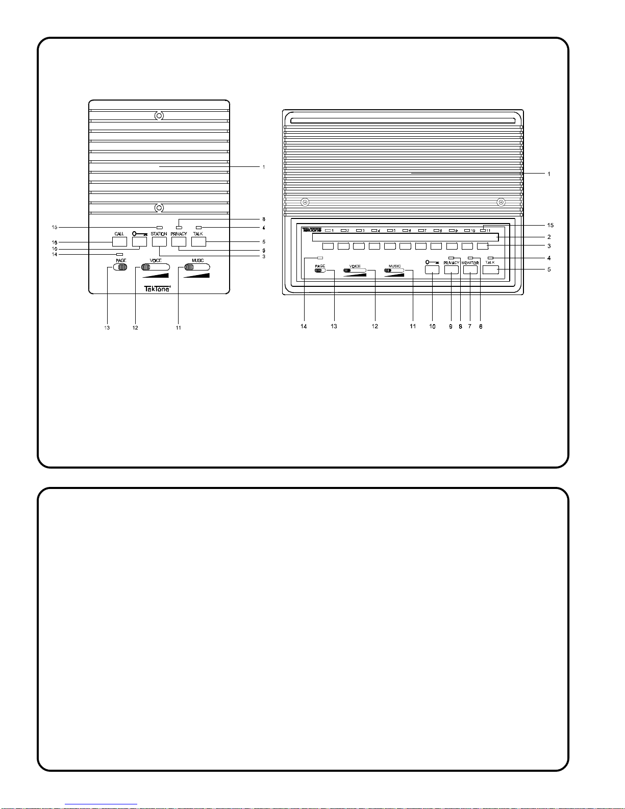
Figure 1 — Master Station Controls and Functions
SM401 SM404/SM406/SM411
1 . Speaker/Microphone 9 . Privacy Switch
2 . Station Directory (SM404/6/11) 10 . Door Release Button
3 . Selector Button 11. Music Volume Control
4. T alk LED 12 . V oice V olume Control
5. T alk Button 13 . Paging Switch (All Call)
6. Monitor LED (SM404/6/11) 14 . Paging LED
7 . Monitor Switch (SM404/6/11) 15 . Station Selector Switch LED
8. Privacy LED 16 . Call Tone Button (SM401)
Figure 2 — System and Options
IR100B Indoor remote with no call capability
IR510B Indoor remote with call button
IR141P Indoor remote with call button and privacy
switch
IR141U Indoor remote with call button and in-use
light (requires RY402 in-use adapter)
IR143P Indoor remote with 3 call buttons and
privacy switch
OR541U Outdoor remote with call button and in-use
light (requires RY402 in-use adapter)
OR601 Outdoor remote with no call capability
OR610 Outdoor remote with call button
OR642 Outdoor remote with illuminated call button
(walnut finish)
OR642W Outdoor remote with illuminated call button
(white finish)
PK400 Power supply
PO001 Door strike
RY400 Remote control relay, 3 outputs
RY401 All-call relay for 12 stations
RY402 In-use adapter
SB205A Paging horn (requires EC105 capacitor and
transformer)
SF400 Call button for use with paging horn
SM401 Master 2 station w/background music, slide
volume, all-call, one LED
SM404 Master 5 station, w/background music, slide
volume, all-call, four LEDs
SM406 Master 7 station, same as above w/6 LED’s
& selector switches
SM 4 1 1 Master 12 station, same as above w/11 LED’s
& selector switches
SS106 Transformer
Page iv • IL603 Tek-SELECT®II Manual
Page 5

Section 1.0 — SYSTEM INSTALLATION
1.1 Installation Procedure
1. Read instructions to determine equipment location and
installation method.
2. Install housings and wiring.
3. Check and connect wiring.
4. Program masters and install stations.
5. Check operation.
1.2 Planning and Equipment Location
NOTE: Do not locate any intercom components or wiring within
3 feet (1 meter) of motors, transformers, fluorescent lights, dimmer switches, electrical wiring or other sources of electrical
interference.
NOTE: It is recommended that special consideration be given
to the system cabling if electromagnetic interference (EMI) or
radio frequency interference (RFI) presents a potential interference problem at a jobsite. The system cabling should be
shielded—or in extreme cases installed in metallic conduit—to
provide protection from extraneous signals or noise. If EMI
(AC hum, ESD, computer or telephone data noise, etc.) and RFI
interference sources are in physical contact (for example, intercom cable is placed on top of AC wiring), then standard
shielded cable protection may be negated.
NOTE: T ekT one
from improper installation.
Masters and Remotes:
1. Do not locate masters near any source of direct heat,
extreme cold, or in areas exposed to dust, oil, chemicals
or excess humidity. Locate stations where they will be
convenient to use. If wall mounted, locate at convenient
operating height.
2. Do not locate stations close to each other (separate
rooms are preferred).
3. Do not locate flush mounted stations back to back on a
common wall.
Power Supply and Relays:
Locate the power supply and other central equipment near
the center of the master-to-master cable run and where
convenient for service.
Do not locate units near any source of direct heat or extreme
cold.
®
is not responsible for interference resulting
Do not connect transformer to power source until wiring is
complete. Observe all local and national electrical codes.
Music System:
Locate music system according to the instructions supplied
with the system. If any area requires music without intercom,
the music system may be located in that area.
1.3 System Housings
IH10 2 Flush mounting ring for indoor remotes
IH110R Flush mounting ring for SM406 and SM411 masters
IH400A Desk cabinet for SM401 and indoor remotes
IH 4 0 1 Desk cabinet for SM404, SM406 and SM411
1.4 Wiring Installation
Master Stations:
Master stations may be loop wired.
Note: Due to common impedance coupling, tone signals
may be amplified and heard by master stations monitoring
other stations. With long wires, this interference may be
quite loud. This effect may be reduced by using two
conductors for the terminal C wire, by using the next larger
size conductor (#20 instead of #22), or by wiring the system
in a star pattern, so that all stations home run to the central
equipment (power supply) location.
If all call relay is not used, limit length of cable as follows:
Wire Size Maximum Total Cable Length
#22 500 feet (150 meters)
#20 800 feet (240 meters)
#18 1200 feet (360 meters)
If the all call relay is used, limit length of cable as follows:
Wire Size Maximum Total Cable Length
#22 250 feet (75 meters)
#20 400 feet (120 meters)
#18 600 feet (180 meters)
Number of wires:
7 common + 1 per station*
SM401 Master Station = 8 wires
SM406 Master Station = up to 13 wires
SM411 Master Station = up to 18 wires
* If no door release operation is required, eliminate one
common. A second common can be eliminated if no remotes
with lighted push buttons are used.
Transformer:
The transformer must be provided with 115 VAC electrical
power. Locate the transformer within 50 feet (15 meters) of
the power supply, and at least 3 feet (1 meter) from master
stations, remote stations and intercom wiring.
Do not locate transformers near any source of heat.
Run cable from master-to-master and to central equipment
location.
Note: Better performance may be obtained by running all
wires to the central equipment (power supply) location.
All Call:
Add 2 wires to master-to-master cable.
IL603 Tek-SELECT®II Manual • Page 1
Page 6

Section 1.0 — SYSTEM INSTALLATION
Background Music:
Add 1 wire to master-to-master cable.
Run 2 wires #18 twisted from music system to central
equipment location, 100 feet (30 meters) maximum.
Run 2 wires #18 twisted from music system to any
background music-only speakers.
Door Release:
Add 1 wire to master-to-master cable.
Run 2 wires #18 from door release to central equipment,
100 feet (30 meters) maximum. Keep this wire away from all
other intercom wires.
Remote to Master Cable:
Limit length of cable as follows:
Wire Size Maximum Total Cable Length
#22 600 feet (180 meters)
#20 1000 feet (300 meters)
Number of wires:
IR143P Remote Station = 4 wires
All other remote stations = 2 wires
For all other remote stations except IR141U, OR541U and
OR642/OR642W, run cable to nearest master station, or to
the central equipment location.
For the IR141U or OR541U remote stations, run cable to
the RY402 in-use adapter.
For the OR642/OR642W remote station, run cable to the
PK400 power supply location.
1.6 Equipment Installation
Surface Mounting SM404, SM406 and SM411 Masters:
1. Install IH401 cabinet on wall. Cabinet may be installed
upside down to allow the front panel to slope upwards,
if required.
2. Connect wires and install SM400 Series Master on
cabinet.
Flush Mounting SM404, SM406 and SM411 Masters:
1. Install IH110R housing as needed.
2. Connect wires and install panel on housing with screws
supplied.
Name Directory for SM404, SM406 and SM411 Masters:
1. Remove button identification cover.
2. Write station names on paper identification strip.
3. Fasten identification strip to master using transparent
tape.
4. Replace button identification cover.
SM401 Master and Remote Stations:
1. Install ring, housing or desk cabinet as needed.
2. Connect wires.
3. Install panel on housing with screws supplied.
SM404, SM406 and SM411 Masters:
The power supply and relay units are surface mounted.
1. Install with screws provided.
Paging Horn:
Limit length of cable as follows:
Wire Size Maximum Total Cable Length
#22 100 feet (30 meters)
#20 200 feet (60 meters)
Notes:
1. A paging horn is a load equivalent to 6 remote stations,
and should not be used with the RY401 All Call Relay
unless the total number of master and remote stations
is less than 6.
2. A paging horn requires the addition of either an EC105
Capacitor or an SF400 Call Button.
1.5 Connections
Make connections as shown on the appropriate wiring diagram. Do not connect any part of the system to AC power
lines. Do not connect transformer to power source until wiring
is complete.
2. Connect wires.
1.7 SM400 Series Installation Instructions
Programming each master to work as desired is accomplished
by setting the dip switches on the back of the master. For most
installations, these dip switches can remain at their factory
settings. The function of these programming switches is as
follows:
Dip
Switch # Name Function
1 MUTE Cancels call tone during intercom use
2 BACK Cancels talk-back on “all call”
3 TIME Cancels call lights timeout after 20
seconds
4 TONE Cancels station calls’ pre-announce
tone
5 BEEP Cancels “all call” pre-announce tone
6 CHIME Enables chime call tone
7 BUZZ Enables buzz call tone
Page 2 • IL603 T ek-SELECT®II Manual
Page 7

Section 1.0 — SYSTEM INSTALLATION
These switches may be set as needed; however, note the following points:
1. The position of dip switches affects only the master
station that the switches are located on.
2. Normally, all master stations should be set the same,
but it is possible to have different settings on each
master if needed.
3. Switches 6 and 7 (
the same time.
4. Switch 2 (BACK) should not be OFF when other masters
have Switch 1 (MUTE) OFF, since the call tone may be
amplified twice, producing a disturbing noise should a
remote call occur during all-call use.
5. The dip switches are set at the factory as shown in
Section 1.8.
CHIME and BUZZ) should not be ON at
1.8 Factory Dip Switch Settings
Dip
Switch # Name Position Function
1 MUTE ON Call tone during intercom
disabled
2 BACK OFF Reply during “all call” enabled
3 TIME OFF Call light timeout enabled
4 TONE ON Station calls’ pre-announce
tone disabled
5 BEEP OFF “All call” pre-announce tone
enabled
6 CHIME ON Chime call tone enabled
7 BUZZ OFF Buzz call tone disabled
Blue (D): This line activates the door release on the PK400
power supply, and is also used when the RY400 remote
control relay is installed.
Violet (F): When this line is shorted to the “N” connection
through a dry contact, the master switches from listen to
talk. (A selector button must be pushed in for this to work.)
Grey (R): This line is the input for background music from
the PK400, and is only needed when a background music
source is connected to the PK400.
White (C): This is the audio common, and is necessary for
system operation.
Black (L): When a master is communicating with another
master or remote, this line causes the TALK light to light red,
indicating that the system is in use. This line also disables
the amplifier on other masters until the master in
communication is switched off again. This line is necessary
for system operation.
Brown/White (M): This line is used for the MONITOR feature.
If this feature will not be used, this line can be omitted.
Red/White (X): This line is the selector line for this master.
This line is only used when there is more than one master
on the system. Connect the “X” connection to the numbered
terminal (1-11) on other master(s) that you want to use to
call this master.
Example: You want to be able to push button 3 on master
A or button 1 on master B to communicate with master C.
To do this you would connect the “X” terminal on master
C to Orange (3) on master A, and also connect it to Brown
(1) on master B.
Call Tone Volume Adjustment:
The call tone volume control may be adjusted with a small
screwdriver on the SM401. It is located on the back of the
station. On the SM406 and SM411, the control is located
behind the removable button identification cover.
1.9 Terminal Reference for Master
Terminals—what they do and when you need them.
Connector 1
Brown (N): This is the Negative of the power supply, and
is necessary for system operation.
Red (B): This is used for the “all call” feature, and is
necessary when the PK401 all call relay is installed.
Yellow (A): This is used for the “all call” feature, and is
necessary when the PK401 all call relay is installed.
Green (P): This is the Positive of the power supply, and is
necessary for system operation.
Connector 2
This connector is the selector button connection for the
master, and is tied to the “X” terminals on other masters or
on remote stations.
Connector 3
These are auxiliary outputs for the selector lines, and are
used with the RY400 remote control relay and the RY402
in-use adapter. When a selector button is pushed, the
corresponding “K” connection goes positive to select the
correct relay output on the RY400, or to light the IN-USE
light on remote stations so equipped.
Note: All master functions are controlled by the TALK light. If
the T ALK light is illuminated red, the selected function will not
operate properly. Wait for the TALK light to go out before selecting any functions.
IL603 Tek-SELECT®II Manual • Page 3
Page 8

Page 4 • IL603 T ek-SELECT®II Manual
Page 9

Section 2.0 — OPERATING INSTRUCTIONS
2.1 Master Station
Call another station:
1. If the TALK light is not illuminated red, select the desired
station by pressing its associated selector button. The
following will occur:
a. The TALK light will illuminate yellow.
b. The selected station
c. If the called station is non-private, sound from the
called station will be heard.
d. Set volume as needed.
Note: If a station button is pressed while the
is red, the called station will not be connected. Press
the selector button again to release it, and wait until the
TALK light goes out. If the station is left selected, it will
be connected when the system is free, but this may
result in an undesirable howling noise if more than one
master was waiting for the system to be free.
2. Press the TALK button to speak, release to listen.
3. When finished, press the selected station button again
to extinguish the CALL and TALK lights.
Answer a call from a master at a remote:
1. The incoming call will be announced by a chime or tone,
and by a green CALL light.
2. If the TALK light is not illuminated red, press the selector
button associated with the illuminated CALL light. The
following will occur:
a. The TALK light will illuminate yellow.
b. The selected station CALL light will change from green
to red.
c. If the called station is non-private, sound from the
calling station will be heard.
CALL light will illuminate red.
TALK light
Open the door (if installed):
1. Press the
DOOR button (identified by a key).
Page all stations (if installed):
1. If the
TALK light is not illuminated red, press the PAGE
switch to the right. The following will occur:
a. The
b. The
TALK light will illuminate yellow.
PAGE light will illuminate yellow.
c. If “talk back” is enabled, sounds from called stations
will be heard.
2. When finished, press the PAGE switch to the left to
extinguish the TALK and PAGE lights.
Monitor a room:
1. If the MONITOR light is not illuminated red, press the
MONITOR button, and then press the button associated
with the desired station. The following will occur:
a. The MONITOR light will illuminate yellow.
b. The MONITOR light associated with the selected station
will illuminate red.
c. If the monitored station is non-private, sounds from
that station will be heard.
d. Set volume as needed.
2. When the intercom is in use by another station, the
monitoring will be interrupted, but will return when the
other station is finished.
3. When finished monitoring, press the selected station
button and the MONITOR button to extinguish the MONITOR
and CALL lights.
Note: Do not attempt to use the MONITOR function if the
MONITOR light is red. To do so may result in a loud noise
from the intercom.
Note: If the station button is pressed while the TALK
light is red, the selected station will not be connected.
Press the selector button again to release it, and wait
until the TALK light goes out.
3. Press the TALK button to speak, release to listen.
4. When finished, press the selected station button again
to extinguish the CALL and TALK lights.
Answer a call from a master at a master:
1. Calls from masters are not indicated by a light, but may
be preceded by a short tone signal. Master calls are
announced by voice.
2. To answer:
a. If the PRIVACY light is illuminated, press the PRIVACY
button to turn privacy off.
b. It is not necessary to operate any other controls.
Reply by voice.
2.2 Remote Station
Call a master:
1. If only one CALL button is available, press the button. If
there is more than one CALL button, press the button to
call the desired master.
2. If the remote has a PRIVACY switch, and if privacy is
selected, press the PRIVACY button to turn the privacy
OFF.
3. Reply by voice when spoken to.
IL603 Tek-SELECT®II Manual • Page 5
Page 10

Page 6 • IL603 T ek-SELECT®II Manual
Page 11
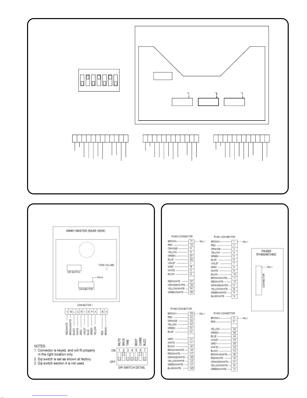
Figure 3 — SM406/SM411
Terminal IDs
BACK
MUTE
13
ON
OFF
DIP SWITCH DETAIL
TONE
TIME
24
BEEP
CHIME
BUZZ
57
6
DIP SWITCH
SM406/SM411 MASTER (REAR VIEW)
PIN K1
PIN 1
PIN N
CONNECTOR 1CONNECTOR 2CONNECTOR 3
CONNECTOR 3
K10
K9
K11
K8K6K7
BLACK
BROWN/WHITE
WHITE
RED\WHITE
GREY
K5
BLUE
VIOLET
K4K2K3
ORANGE
YELLOW
RED
K1
BROWN
CONNECTOR 2
10
BLACK
BROWN/WHITE
WHITE
RED/WHITE
GREY
54 12911768
VIOLET
BLUE
GREEN
3
ORANGE
RED
BROWN
CONNECTOR 1
R
BROWN/WHITE
BLACK
WHITE
RED/WHITE
GREY
DNBAPMLXFC
BLUE
GREEN
VIOLET
YELLOW
NOTES: 1. Connectors are keyed, and will fit properly in the right location only.
2. Dip switch is set as shown at factory.
Figure 4 — SM401 Terminal IDs Figure 5 — PK400/RY400 Series
Terminal IDs
RED
BROWN
IL603 Tek-SELECT®II Manual • Page 7
Page 12
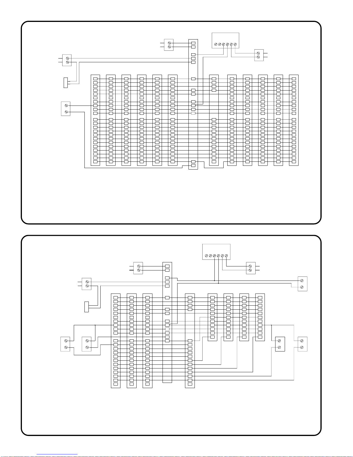
Figure 6 — SM411 Master to Master
Wiring Diagram
SS106
T
R
A
N
S
F
O
R
M
E
R
SM411
PO001
DOOR
RELEASE
OR642
OUTDOOR
REMOTE
C
X
SM411
MASTER
N
B
A
P
D
F
R
C
L
M
X
1
2
3
4
5
6
7
8
9
10
11
NOTES:
1. Actual terminal locations not shown. See terminal identification diagrams.
2. Connect power transformers to 115 V.A.C. in accord with local electrical codes.
3. For wire size and maximum length, see the installation instructions.
4. If the music system is not used, delete wires to terminals R, R1 and R2.
5. If the door release is not used, delete wires to terminals D, and D1.
6. If any station should not receive all call, do not connect the X terminal for that station
to the RY401 all call relay ( note OR641 remote, connected to terminal 11, in the above diagram).
7. If a lighted outdoor remote is not used, connect terminal X directly to the SM411 (terminal 11
in the above diagram), and do not use PK400 terminals E1 and E2.
MASTER
N
B
A
P
D
F
R
C
L
M
1
X
2
3
4
5
6
7
8
9
10
11
SM411
MASTER
N
B
A
P
D
F
R
C
L
M
1
2
X
3
4
5
6
7
8
9
10
11
SM411
MASTER
N
B
A
P
D
F
R
C
L
M
1
2
3
X
4
5
6
7
8
9
10
11
SM411
MASTER
N
B
A
P
D
F
R
C
L
M
1
2
3
4
X
5
6
7
8
9
10
11
SS106
TRANSFORMER
24 V.A.C.
SM411
MASTER
N
B
A
P
D
F
R
C
L
M
1
2
3
4
5
X
6
7
8
9
10
11
PK400
POWER SUPPLY
T2
T1
R2
D1
D2
N
P
D
R1
C
L
M
E1
E2
RY401
ALL CALL
RELAY
N
B
A
P
1
2
3
4
5
6
7
8
9
10
11
12
EK714AW
MUSIC SYSTEM
41 S32 T
SM411
MASTER
SS102A
TRANSFORMER
16 V.A.C.
SM411
MASTER
N
N
B
B
A
A
P
P
D
D
F
F
R
R
C
C
L
L
M
M
1
1
2
2
3
3
4
4
5
5
6
6
X
7
7
X
8
8
9
9
10
10
11
11
SM411
MASTER
N
B
A
P
D
F
R
C
L
M
1
2
3
4
5
6
7
8
X
9
10
11
SM411
MASTER
N
B
A
P
D
F
R
C
L
M
1
2
3
4
5
6
7
8
9
X
10
11
SM411
MASTER
N
B
A
P
D
F
R
C
L
M
1
2
3
4
5
6
7
8
9
10
X
11
Figure 7 — SM411 Intermix
Wiring Diagram
SS106
TRANSFORMER
PO001
DOOR
RELEASE
OR610
OUTDOOR
REMOTE
C
X
OR642
OUTDOOR
REMOTE
C
X
EK714
MUSIC SYSTEM
SM411
MASTER
N
B
A
P
D
F
R
C
L
M
1
2
X
4
5
6
7
8
9
10
11
3
SS106
TRANSFORMER
24 V.A.C.
SM411
MASTER
N
B
A
P
D
F
R
C
L
M
1
2
3
X
5
6
7
8
9
10
11
4
SM411
MASTER
N
B
A
P
D
F
R
C
L
M
1
2
3
4
X
6
7
8
9
10
11
5
PK400
POWER SUPPLY
T2
T1
R2
D1
D2
N
P
D
R1
C
L
M
E2
E1
RY401
ALL CALL
RELAY
N
B
A
P
1
2
3
4
5
6
7
8
9
10
11
12
SM401
MASTER
N
B
A
P
D
1
R
C
L
M
X
41 S32 T
SM401
MASTER
N
B
A
P
D
1
R
C
L
M
X
SS102A
TRANSFORMER
SM401
MASTER
N
B
A
P
D
1
R
C
L
M
X
NOTES:
1. Actual terminal locations not shown. See terminal identification diagrams.
2. Connect power transformers to 115 V.A.C. in accord with local electrical codes.
3. For wire size and maximum length, see the installation instructions.
4. If lighted outdoor remotes are not used, terminals E1 and E2 do not need to be used.
5. If the music system is not used, delete wires to terminals R, R1 and R2.
6. If the door release is not used, delete wires to terminals D, and D1.
7. The IR100B station receives music but cannot make or receive intercom calls.
16 V.A.C.
SM401
MASTER
N
B
A
P
D
1
R
C
L
M
X
IR141
INDOOR
REMOTE
C
X
IR100B
INDOOR
REMOTE
X
C
IR141
INDOOR
REMOTE
C
X
Page 8 • IL603 T ek-SELECT®II Manual
Page 13
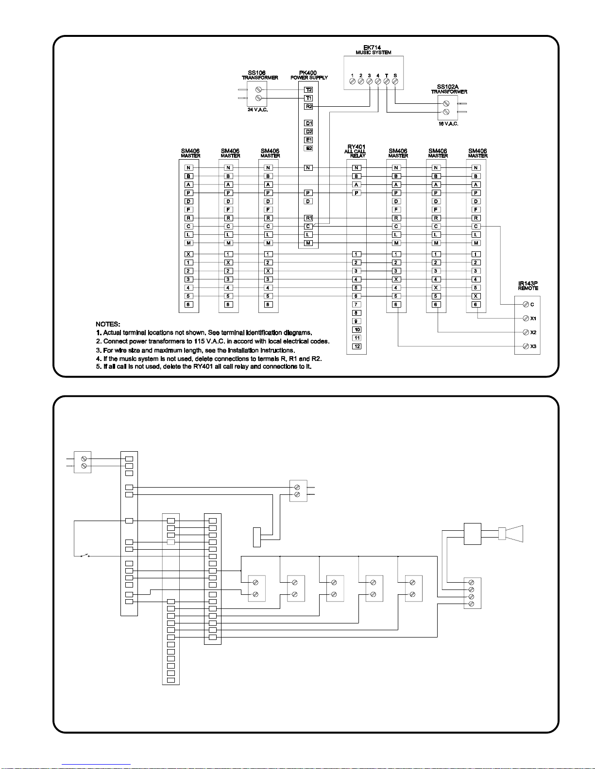
Figure 8 — SM406 Master to Master
Wiring Diagram
Figure 9 — SM406 Master to Remote
Wiring Diagram
SS106
TRANSFORMER
24 V.A.C.
FOOT SWITCH
PK400
POWER SUPPLY
T2
T1
R2
D1
D2
N
P
D
R1
C
L
M
E2
E1
RY401
ALL CALL
RELAY
N
B
A
P
1
2
3
4
5
6
7
8
9
10
11
12
SM406
MASTER
N
B
A
P
D
F
R
C
L
M
X
1
2
3
4
5
6
OR642/OR642W
NOTES:
1. Actual terminal locations not shown. See terminal identification diagrams.
2. Connect power transformers to 115 V.A.C. in accord with local electrical codes.
3. For wire size and maximum length, see the installation instructions.
4. If a lighted outdoor remote is not used, it is not necessary to use terminals E1 and E2.
5. If the door release is not used, delete connection to terminals D, and D1.
6. If the SF400 call button is not used, replace it with an EC105 capacitor in series.
7. If the paging horn is not connected to the all call relay, the 25V audio transformer is not needed.
SS106
TRANSFORMER
PO001
DOOR PAGING HORN
RELEASE
OUTDOOR
REMOTE
C
X
OR610
OUTDOOR
REMOTE
C
X
IR141P
INDOOR
REMOTE
IR141P
INDOOR
REMOTE
C
X
IR510B
INDOOR
REMOTE
C
X
C
X
25V AUDIO
TRANSFORMER
SF400
CALL BUTTON
SB205A
H
H
C
X
IL603 Tek-SELECT®II Manual • Page 9
Page 14
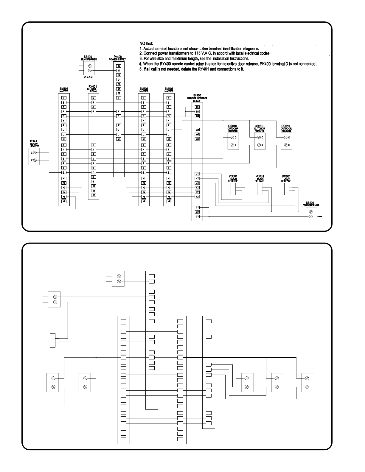
Figure 10 — SM406/RY400
Wiring Diagram
Figure 11 — SM406/RY402
Wiring Diagram
SS106
TRANSFORMER
PO001
DOOR
RELEASE
IR141
INDOOR
REMOTE
C
X
IR141
INDOOR
REMOTE
C
X
SS106
TRANSFORMER
24 V.A.C.
SM406
MASTER
N
B
A
P
D
F
R
C
L
M
X
1
2
3
4
5
6
K1
K2
K3
K4
K5
K6
PK400
POWER SUPPLY
T2
T1
R2
D1
D2
E1
E2
N
P
D
R1
C
L
M
NOTES:
1. Actual terminal locations not shown. See terminal identification diagrams.
2. Connect power transformers to 115 V.A.C. in accord with local electrical codes.
3. For wire size and maximum length, see the installation instructions.
4. If the door release is not used, delete connections to terminals D and D1.
SM406
MASTER
N
B
A
P
D
F
R
C
L
M
1
X
2
3
4
5
6
K1
K2
K3
K4
K5
K6
RY402
IN-USE
ADAPTER
N
P
S1
S2
S3
X1
X2
X3
K1
K2
K3
OR541U
OUTDOOR
REMOTE
C
S
IR141U
INDOOR
REMOTE
C
S
IR141U
INDOOR
REMOTE
C
S
Page 10 • IL603 Tek-SELECT®II Manual
Page 15
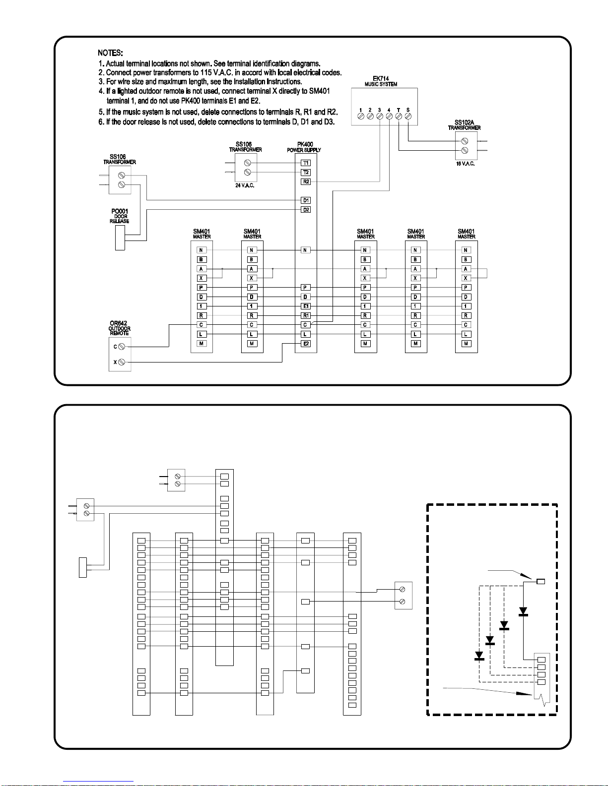
Figure 12 — SM401
Wiring Diagram
Figure 13 — RY401 and RY402
application with SM404 Master
SS106
TRANSFORMER
PO001
DOOR
RELEASE
SM404
MASTER
N
B
A
P
D
F
R
C
L
M
X
2
3
1
4
K1
K2
K3
K4
SS106
TRANSFORMER
24 V.A.C.
SM404
MASTER
N
B
A
P
D
F
R
C
L
M
1
X
3
2
4
K1
K2
K3
K4
PK400
POWER SUPPLY
NOTES:
1. Actual terminal locations not shown. See terminal identification diagrams.
2. Connect power transformers to 115 V.A.C. in accord with local electrical codes.
T2
T1
R2
D1
D2
E1
E2
N
P
D
R1
C
L
M
3. For wire size and maximum length, see the installation instructions.
4. If the door release is not used, delete connections to terminals D and D1.
5. RY402 should always have a "direct" connection to the PK400's "N" terminal.
SM404
MASTER
N
B
A
P
D
F
R
C
L
M
1
2
X
3
4
K1
K2
K3
K4
RY402
IN-USE
ADAPTER
N
P
S1
X1
K1
RY401
ALL CALL
RELAY
N
B
A
P
1
2
3
4
5
6
7
8
9
10
11
12
OR541U
OUTDOOR
REMOTE
NOTE:
Use only if RY401 and RY402
are installed together
Separate diode required for
each RY402 circuit used.
Any "B" Terminal in the system
C
S
1N4003
Diode
RY402
B
K1
K2
K3
K4
Above is needed only
NOTE:
at one master on the system
IL603 Tek-SELECT®II Manual • Page 11
Page 16

 Loading...