

TekTone Tek-ENTRY TE903A, Tek-ENTRY TE904, Tek-ENTRY TE905A Operation, Installation And Service Manual
Page 1

IL573
SECTION A
Rev . 12 - 12/2009
Tek-ENTRY® Telephone Entry System
Phone-Line Version
www.tektone.com
Operation, Installation and Service Manual
Phone: (828) 524-9967
Toll-Free: (800) 327-8466
T ech Support: Option 2
Sales: Option 3
277 Industrial Park Road
Franklin, NC 28734
[email protected]
Fax: (828) 524-9968
Page 2

Operation, Installation and Service Manual
Copyright © 2002–2009 TekTone® Sound & Signal Mfg., Inc., All rights reserved.
No part of this publication may be copied without the express written permission of T ekT one® Sound & Signal Mfg., Inc. The content
of this manual is furnished for informational use only, is subject to change without notice, and should not be construed as a c ommitment
by T ekT one® Sound & Signal Mfg., Inc. T ekTone® Sound & Signal Mfg., Inc. assumes no responsibility or liability for any errors or
inaccuracies that may appear in this documentation.
T ekTone, the T ekTone logo, T ek-Call, Tek-Care, Tek-Check-In, T ek-Com, Tek-Digicare, Tek-Door, Tek-Entry III, Tek-Guard, TekMicro, Tek-Micro II, Tek-MMARS II, TekNIOS, TekNIOS II, Tek-Paging, Tek-Phone, Tek-Safe, Tek-Select II, Tek-Sentry, TekSound, T ek-S tatus, Tek-Trio and Tek-V iew are either registered trademarks or trademarks of TekTone® Sound & Signal Mfg., Inc. in
the United States and/or other countries. All other trademarks are the property of their respective owners.
TekTone® Sound & Signal Mfg., Inc., 277 Industrial Park Road, Franklin, North Carolina 28734, USA.
ii • IL573 Tek-ENTRY® Telephone Entry System Phone-Line Version Manual Copyright © TekTone Sound & Signal Mfg., Inc. All Rights Reserved.
Page 3

Table of Contents ————————————————————
System Introduction ............................................................................... 1
General Features.......................................................................................................... 1
Special Features........................................................................................................... 1
Postal Service Lock.............................................................................................. 1
Door Timer Cut-Off (T ailgate Prevention)........................................................... 1
Fire Alarm (Emergency) Input ............................................................................. 1
Multiple Entrances ............................................................................................... 1
Night Service........................................................................................................ 1
Wiegand Data Output........................................................................................... 1
System Installation and Programming ..................................................2
Installation Tips ........................................................................................................... 2
System Installation Step by Step ................................................................................. 2
System Programming and Settings .............................................................................. 5
Program Mode—Begin/End................................................................................. 5
To Program Codes (Tenant Dial Codes) .............................................................. 5
View Suite Codes (Tenant Dial Codes) ................................................................ 6
Keyless Entry Codes ............................................................................................ 6
View Keyless Codes............................................................................................. 6
New Master Code................................................................................................. 6
7, 10 or 11 Digit Programming ............................................................................ 6
Pulse or Tone Dialing........................................................................................... 7
Door Open Time................................................................................................... 7
T alk Time ............................................................................................................. 7
Night Service (Guard Telephone) ........................................................................ 7
Rotary Phones ...................................................................................................... 7
Guard T elephone Number .................................................................................... 8
Erase/Reset to Factory Default............................................................................. 8
Adjustments ............................................................................................................... 8
Volume Control .................................................................................................... 8
Rotary Phone Pulse Sensitivity ............................................................................ 8
Notice to U.S. Installers and Users.............................................................................. 9
Notice to Canadian Installers and Users.................................................................... 10
Illustrations
Figure 1—System Wiring Diagram (TE903A, TE904, TE905A)............................... 3
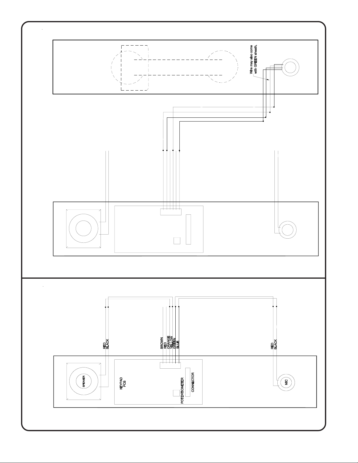
Figure 2—Hands-Free Panel W iring Diagram ............................................................ 4
Figure 3—Handset Panel W iring Diagram.................................................................. 4
Figure 4—PM900 Control Unit Mounting Template ................................................ 11
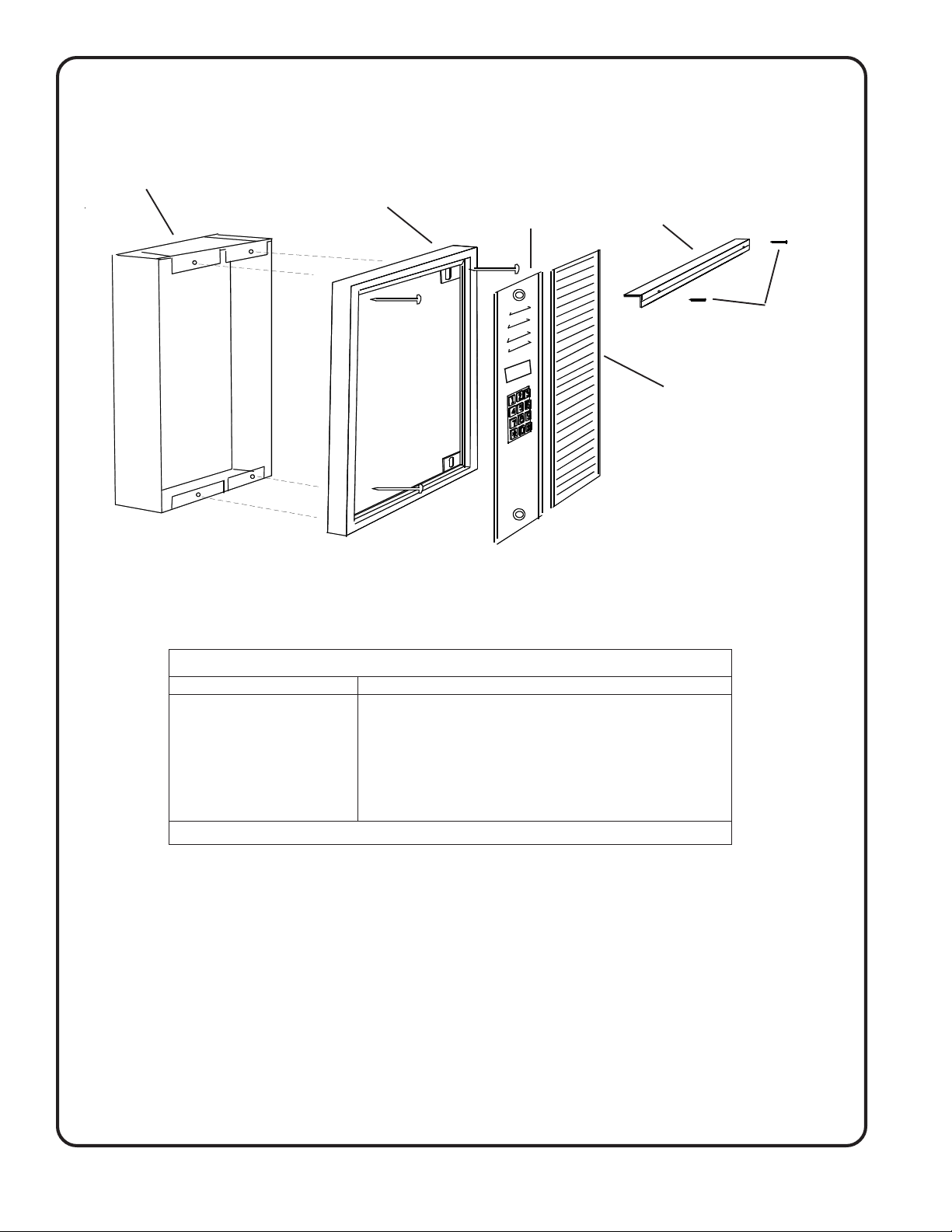
Figure 5—Frame and Housing Installation ............................................................... 12
Worksheets
Programming W orksheet ........................................................................................... 13
Directory W orksheets .......................................................................................... 14–18
Tek-ENTRY® Telephone Entry System Operating Instructions ................................ 19
IL573 Tek-ENTRY® Telephone Entry System Phone-Line Version Manual • iiiCopyright © TekTone Sound & Signal Mfg., Inc. All Rights Reserved.
Page 4

Page 5

System Introduction ———————————————————
General Features
Tek-ENTRY® Telephone Entry Systems are designed for easy operation and accommodate
1–750 suites with 7-, 10- or 11-digit phone numbers. The system has many sophisticated
features built in, such as:
• All programming is done via the system keypad.
• EEPROM Memory retains programmed information during total power failure.
• Two programmable relay outputs control door strikes, gates, cameras, etc.
• System operates with both touchtone and rotary pulse phones.
• Automatic call termination after 8 seconds of dial tone detection.
• Microphone Mute prevents unauthorized entry using a tone generator.
• Variable tenant code length: 1, 2, 3 or 4 digits.
• One keyless entry code per tenant, plus five for use by building management.
• Tenant codes can be actual suite numbers or coded for security purposes.
• May be programmed with any combination of 7, 10 or 11 digit phone numbers.
Special Features
Postal Service Lock
Provision for the installation of a postal service lock is available on the rear of the system
enclosure’s control panel.
Door Timer Cut-Off (Tailgate Prevention)
This feature requires the installation of a “Normally Open” switch contact that closes
when the entry door has been opened. A magnetic contact, as used in security systems, is
acceptable for this application, provided that it is a “Normally Open” type. (Most security
door contacts are of the “Normally Closed” type.) When the electric door strike is released,
the door remains open for the period of time that has been programmed. When the door
timer cut-off feature is used, the door strike de-energizes as soon as the system senses
that the entry door has been opened. This causes the door to lock when it closes, regardless
of the programmed time. The door strike is therefore energized only as long as necessary ,
to prevent unauthorized entry of individuals who follow behind the visitor (tailgating).
Fire Alarm (Emergency) Input
Connecting a “Normally Open” alarm contact from the building fire alarm system causes
the electric door strike to pulse on and off in the event of a fire (emergency) situation.
This effectively leaves the entry door unlocked for the duration of the emergency.
Multiple Entrances
Accommodating multiple entry doors is a built-in feature of the T ek-ENTR Y® T elephone
Entry Systems. Up to 20 entry systems can be interconnected without additional switching
equipment, and all systems can be connected to one common telephone line. One additional
pair of wires, parallel connected to terminals “ME” and “G” of all entry systems, is
required. When one entry panel is in use, the other panels are temporarily disabled and
display a “SYSTEM IN USE” message. (NOTE: Each entry panel must be independently
powered and programmed, and requires a telephone extension jack at that location.)
Night Service
This feature redirects all entry system calls to a pre-designated telephone number (guard
phone). When this feature is enabled (by entering “*456”), the entry system displays the
“Night Service On” message. To return to normal operation, re-enter “*456”.
Wiegand Data Output
Copyright © TekTone Sound & Signal Mfg., Inc. All Rights Reserved.
This feature connects the T ek-ENTR Y® T elephone Entry System to a card access system
with a W iegand 26-bit input. When a tenant approves a visitor, the tenant’s code is sent
to the card access system, causing the door to open.
IL573 Tek-ENTRY® Telephone Entry System Phone-Line Version Manual • 1
Page 6

System Installation and Programming –——————————
Installation Tips
1. Make arrangements with the telephone company to install a telephone line for use by
the system. Install the telephone line jack inside the entry panel enclosure. When
ordering, specify the equipment DOC approval number (1949 5264 A).
2. One 16 volt/20 VA UL® Listed and CSA approved class 2 power transformer is
required for system operation. A second transformer is required for door strike
activation. This transformer should have the necessary voltage and current rating for
the door strike that is to be used (max. 28 volts, 3 amps).
3. Transformers and remote devices such as the door strike, fire alarm and door contacts
must be wired to the system controller located in the enclosure housing. A wiring
channel at the rear of the system enclosure must be provided for these devices. Follow
local building code requirements for low voltage wiring.
4. If a postal service lock is to be installed, make arrangements with the local post office
to supply the lock.
5. In multiple entrance applications, two additional wires are required from each entry
system to interconnect the system controllers. A telephone line extension jack must
also be installed at each entry location (see Figure 1—System Wiring Diagram).
6. Do not mount the entry panel in an area where it may be exposed to near-horizontal
water or moisture sources, for example driving rain or water spray.
System Installation Step by Step
Refer to Figure 1—System W iring Diagram for terminal locations. Also refer to Figur e 2—
Hands-Free Panel Wiring Diagram and Figure 3—Handset Panel Wiring Diagram.
1. Mount the system enclosure to the wall in the location closest to the building’s
controlled entry point. (Refer to Figure 5—Frame and Housing Installation.)
2. Connect the door strike wires to terminals “D1” and “D2” if DC (silent) operation is
desired, or to terminals “D3” and “D4” for AC (buzzing) operation. The maximum
switched door strike load is 28 volts at 3 amps.
3. An auxiliary switched device (such as a parking gate) may be controlled through the
auxiliary relay contact that is available by connecting to terminals “NC” (normally
closed), “C” (common), and “NO” (normally open). The maximum switched auxiliary
load is 28 volts at 3 amps. This contact will change to the energized state for one second
when the tenant dials “6” from their DTMF (touchtone) telephone.
4. Terminal “PL” is for the postal service lock. Closing of a normally open switch
between terminals “PL”and “G” is required for activation. The system is pre-wired for
this service, but requires a lock to be installed on the rear of the system control panel
(optional on TE905A). Remove the panel plug button for the postman’s key and
remove the retaining strap on the switch actuator. Mount the lock with the supplied
hardware. Adjust the switch actuator for proper operation with the lock.
5. Terminal “TC” is for connection of a door timer cut-off contact. A normally open
contact that closes when the door has been opened will cut-off the door timer and
instantly re-lock the door. This is used to prevent tailgating of unwanted visitors
through the entry doors. Connect between terminals “TC” and “G.”
6. Terminal “FA” is for connection to the building fire alarm system. A normally open
alarm contact that closes during an alarm condition can be connected between
terminals “FA” and “G” to pulse open the entry door during a fire or other emergency.
2 • IL573 Tek-ENTRY® Telephone Entry System Phone-Line Version Manual
Copyright © TekTone Sound & Signal Mfg., Inc. All Rights Reserved.
Page 7
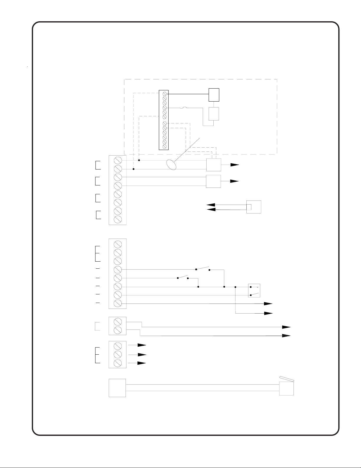
Figure 1—System Wiring Diagram (TE903A, TE904, TE905A)
Note:
To battery backup door
release, repeat this section
on T3 and T4 connections.
SYSTEM POWER
16 VAC 20 VA
DOOR STRIKE
TRANSFORMER
D.C. (SILENT) +
DOOR STRIKE -
A.C. (BUZZING)
DOOR STRIKE
AUXILIARY RELAY
MOMENTARY CONTACT
POSTAL LOCK
DOOR TIMER CUTOFF
COMMON
FIRE ALARM INPUT
MULTIPLE ENTRANCE
TELEPHONE LINE
CONNECTIONS
HARDWIRE TO
TO "R" & "T" TERMINALS
OR USE JACK
T1
T2
T3
T4
D1
D2
D3
D4
NO
C
NC
PL
TC
G
FA
ME
R
T
PK124
Battery Charger
C
4 AMP FUSE
B
P
T1
T2
18 AWG 16 VAC
18 AWG
CONNECT DOOR
STRIKE TO D.C. OR A.C.
OUTPUTS. MAXIMUM OUTPUT
IS 28V, 3AMP.
POSTAL LOCK
N.O. SWITCH
N.O. SWITCH
BA001
12V Battery
BA001
12V Battery
NOTE: IF USING
BATTERY HOOK-UP,
DO NOT CONNECT
T1 & T2 TO TRANSFORMER
120 VAC
120 VAC
18 AWG
FIRE ALARM
N.O. CONTACT
DOOR STRIKE
TRANSFORMER MUST BE
COMPATIBLE TO STRIKE
DOOR STRIKE
MULTIPLE ENTRANCE
TO NEXT TELEPHONE
CONTROLLER SYSTEM.
(G TO G & ME TO ME)
TO TELEPHONE LINE
-OR-
D1
D0
G
Copyright © TekTone Sound & Signal Mfg., Inc. All Rights Reserved.
Wiegand Output
Format: 26 bit Wiegand
Voltage: 5 VDC
Open Collector: No
Pulse: 50 uSec. Duration: 1 mSec.
TO TELEPHONE
JACK
IL573 Tek-ENTRY® Telephone Entry System Phone-Line Version Manual • 3
Page 8
PANEL
(Rear View)
HANDSET
BLACK
WHITE
WHITE
RED
Wiring Diagram
Figure 3—Handset Panel
NOT CONNECTED
}
BLUE
GREEN
RED
ORANGE
RED
BLACK
PCB
KEYPAD
BROWN
S
+
M
YELLOW
-+
MIC SP
CONNECTOR
POTENTIOMETER
NOT CONNECTED
}
BLACK
RED
+
+
-
M
-
S
MIC
SP
Wiring Diagram
Figure 2—Hands-Free Panel
4 • IL573 Tek-ENTRY® Telephone Entry System Phone-Line Version Manual
Copyright © TekTone Sound & Signal Mfg., Inc. All Rights Reserved.
Page 9

System Installation and Programming
7. Terminal “ME” is the interconnect point for multiple entrance systems. Interconnect
terminals “ME” and “G” of all entry systems to allow operation with a common
telephone line. Each location must also be wired with its own transformer, door strike,
extension telephone jack, switch contacts, etc., as shown on Figure 1—System Wiring
Diagram. Each location must be programmed separately.
8. At this point, double-check all wiring for shorts and opens.
9. Connect door strike transformer to terminals “T3” and “T4.” The maximum door strike
load that may switch through the controller is 28 volts at 3 amps.
10. Connect 16 VAC from the system transformer to terminals “T1” and “T2” on the
system controller terminal block. (This transformer must not be used to power any
other devices, such as the door strike.) The display will illuminate and the message
“WELCOME…DIAL CODE NUMBER” will appear.
11.Connect the supplied telephone cord from the jack or terminals “R” and “T” on the
system controller to the telephone line jack supplied by the telephone company.
System Programming and Settings
All programming of the entry system is accomplished through the use of the system keypad
and the display located on the control panel. Use the supplied Tek-ENTRY® T elephone Entry
System Directory Worksheets to generate a record of the building occupants, their suite
numbers, telephone numbers, assigned dial codes, and keyless entry codes. These sheets
will be required for programming, as well as when changes are to be made.
Complete the Tek-ENTRY® Telephone Entry System Programming Worksheet, and ensure
that it, the Tek-ENTRY® T elephone Entry System Directory W orksheets and the User Operating
Instructions are given to building management when installation and programming are
complete.
Program Mode—Begin/End
Enter “*” and the three-digit master code (default is *123) to begin a programming session.
Use the “1” key on the keypad to scroll up the programming menu and the “3” key to
scroll down. When the desired function is displayed on the screen, press the “#” key to
select it. Follow the displayed instructions to make the necessary changes. When
programming is complete, end program mode by pressing the “*” key twice.
To Program Codes (Tenant Dial Codes)
T enant dial codes are used at the entrance panel to call a tenant, and are usually listed on
a tenants directory . Suite numbers may be used as tenant dial codes, if desired. T o program
tenant dial codes and their corresponding telephone numbers into the system:
1. When the programming menu displays “TO PROGRAM CODES,” press the “#” key.
2. Enter the 4-digit tenant dial code, and then the tenant’s telephone number. Press the “#”
key to save. Continue in this fashion until all tenant dial codes and telephone numbers
have been entered. If a tenant dial code is fewer than 4 digits in length, enter zeros as
leading digits. The leading zeros are not needed during actual use, but are required
during programming. If an error is made when entering a tenant dial code or telephone
number, press the “*” key to backspace.
3. Press the “*” key to return to the programming menu.
4. If desired, press the “*” key to end program mode.
Copyright © TekTone Sound & Signal Mfg., Inc. All Rights Reserved.
IL573 Tek-ENTRY® Telephone Entry System Phone-Line Version Manual • 5
Page 10

System Installation and Programming
View Suite Codes (Tenant Dial Codes)
Use this function to review and/or delete tenant dial codes and telephone numbers
1. When the programming menu displays “VIEW SUITE CODES,” press the “#” key.
The message “CODE TO REVIEW, _______” will appear.
2. Enter the four-digit tenant dial code to be reviewed. The dial code and associated
telephone number will be displayed.
3. To delete the displayed tenant dial code and telephone number, press the “#” key.
4. To view all tenant dial codes and telephone numbers, use the “1” key to scroll up, and
the “3” key to scroll down.
5. Press the “*” key to return to the programming menu.
6. If desired, press the “*” key to end program mode.
Keyless Entry Codes
Keyless entry codes allow tenants to enter through the controlled doors using a four-digit
code from the system keypad, rather than a key. During actual use, this code must be
preceded by the “#” key so that the code is not visible on the display . For security , assign
each tenant a unique keyless entry code, and do not duplicate any suite numbers or tenant
dial codes.
1. When the programming menu displays “ENTER KEYLESS CODES,” press the “#”
key. The message “KEYLESS ENTRY CODE #____” will appear.
2. Enter a four-digit code and press the “#” key to save. Continue entering keyless entry
codes until all are entered.
3. Press the “*” key to return to the programming menu.
4. If desired, press the “*” key to end program mode.
View Keyless Codes
This section allows the review and/or deletion of keyless entry codes.
1. When the programming menu displays “VIEW KEYLESS CODES,” press the “#”
key. The message “CODE TO REVIEW _____” will appear.
2. Enter the four-digit keyless entry code to be reviewed. The keyless entry code will be
displayed.
3. To delete the displayed keyless entry code, press the “#” key.
4. To view all keyless entry codes, use the “1” key to scroll up, and the “3” key to scroll
down.
5. Press the “*” key to return to the programming menu.
6. If desired, press the “*” key to end program mode.
New Master Code
The master code is used to access the program mode. When the entry system is shipped
from the factory, its master code is set to “*123.” It is advisable to change the master
code and record the new code in the appropriate place on the Tek-ENTRY® Telephone
Entry System Programming Worksheet. The master code is used by the installation
company or by authorized personnel, only when programming is necessary. To change
the master code:
1. When the programming menu displays “NEW MASTER CODE,” press the “#” key.
The message “MASTER CODE *123” will appear.
2. Enter a new three-digit master code and press the “#” key to save.
3. Press the “*” key to return to the programming menu.
4. If desired, press the “*” key to end program mode.
7-, 10- or 11-Digit Programming
This function changes the phone number length that the system expects when Tenant
Dial Codes are being programmed. Factory default is 7-digit phone numbers. Any
combination of 7-, 10- and 11-digit phone numbers may be programmed: program all the
6 • IL573 Tek-ENTRY® Telephone Entry System Phone-Line Version Manual
Copyright © TekTone Sound & Signal Mfg., Inc. All Rights Reserved.
Page 11

System Installation and Programming
7-digit phone numbers, then change this setting to 10- or 11-digit phone numbers and
program those numbers.
1. When the programming menu displays “7, 10 OR 11 DIGITS?, ” press the “#” key. The
message “TYPE 07, 10 OR 11 DIGITS” will appear.
2. Enter “07” to program 7-digit numbers; enter “10” to program 10-digit numbers; or
enter “11” to program 11-digit numbers. Press the “#” key to save.
3. Press the “*” key to return to the programming menu.
4. If desired, press the “*” key to end program mode.
Pulse or Tone Dialing
This item selects the type of dialing used by the system controller—DTMF (touchtone)
or pulse. Factory default is DTMF . The setting must correspond to the type of telephone
line that has been installed for the entry system.
1. When the programming menu displays “PULSE OR TONE,” press the “#” key. The
message “PULSE OR TONE” will appear.
2. Enter “00” for Pulse (Rotary) dialing; or enter “11” for Tone (DTMF) dialing. Press
the “#” key to save.
3. Press the “*” key to return to the programming menu.
4. If desired, press the “*” key to end program mode.
Door Open Time
The door open time can be reprogrammed to 0-99 seconds to prevent tailgating. Factory
default is 10 seconds. See Door Timer Cut-Off in the System Introduction—Special
Features section for more information.
1. When the programming menu displays “DOOR TIME,” press the “#” key. The
message “DOOR OPEN TIME” will appear.
2. Enter a two-digit time in seconds and press the “#” key to save.
3. Press the “*” key to return to the programming menu.
4. If desired, press the “*” key to end program mode.
Talk Time
T alk time can be reprogrammed to 0-99 seconds to set the maximum conversation length
between a visitor and tenant. (Note: Talk time starts when visitor dials tenant.) Factory
default is 60 seconds.
1. When the programming menu displays “TALK TIME,” press the “#” key. The
message “TALK TIME” will appear.
2. Enter a two-digit time in seconds and press the “#” key to save.
3. Press the “*” key to return to the programming menu.
4. If desired, press the “*” key to end program mode.
Night Service (Guard Telephone)
When enabled, the night service on feature redirects all entry system calls to the guard
telephone. Factory default is “disabled.” See Night Service in the System Introduction—
Special Features section for more information.
1. When the programming menu displays “NIGHT SERVICE?,” press the “#” key. The
message “ENABLE/DISABLE” will appear.
2. Enter “00” to enable night service; or enter “11” to disable night service. Press the “#”
key to save.
3. Press the “*” key to return to the programming menu.
4. If desired, press the “*” key to end program mode.
Rotary Phones
Copyright © TekTone Sound & Signal Mfg., Inc. All Rights Reserved.
When rotary phone use is enabled, tenants may use either rotary (pulse) or touchtone
phones with the system. When disabled, tenants may use only touchtone phones. Factory
default is “disabled.”
IL573 Tek-ENTRY® Telephone Entry System Phone-Line Version Manual • 7
Page 12

System Installation and Programming
1. When the programming menu displays “ROTARY PHONES?,” press the # key. The
message “ENABLE/DISABLE” will appear.
2. Enter “00” to enable rotary phone use; or enter “11” to disable rotary phone use. Press
the “#” key to save.
3. Press the “*” key to return to the programming menu.
4. If desired, press the “*” key to end program mode.
Guard Telephone Number
This is the telephone number that all calls will be routed to when night service is enabled.
See Night Service in the System Introduction—Special Features section for more
information.
1. When the programming menu displays “GUARD PHONE,” press the “#” key. The
message “GUARD PHONE NO.” will appear.
2. Enter a telephone number and press the “#” key to save.
3. Press the “*” key to return to the programming menu.
4. If desired, press the “*” key to end program mode.
Erase/Reset to Factory Default
This function erases all programming, including Tenant Dial Codes and Keyless Entry
Codes, and returns the system to factory defaults.
1. When the programming menu displays “ERASE/RESET TO FACTORY DEFAULT,”
press the “#” key. The message “ARE YOU SURE? *=NO #=YES” will appear.
2. Enter “*” to retain system programming; or enter “#” to erase all programming and
return to factory defaults.
3. Press the “*” key to return to the programming menu.
4. If desired, press the “*” key to end program mode.
Adjustments
Volume Control
The communication volume levels are factory preset for normal operations. The levels can
be increased or decreased by adjusting the potentiometers located along the bottom of the
system controller, behind the front display plate. Audio level from the entry system to the
suite is controlled by the MICROPHONE VOLUME control. Audio level from the suite to the entry
system is controlled by the SPEAKER VOLUME control.
Rotary Phone Pulse Sensitivity
Telephone companies do not specify or guarantee the waveshape of the signal transmitted
when the tenant dials the digit “9” from a rotary (pulse) telephone. In order to achieve best
results, T ek-ENTR Y® Telephone Entry Systems are furnished with a sensitivity adjustment
potentiometer, as well as an indicator lamp to view the incoming rotary signal (pulses). This
potentiometer is labeled PULSE SENSITIVITY on the system controller . The pulse sensitivity is
factory preset so that a wide range of incoming rotary signals will properly trigger the door
circuit, and so will usually not require adjustment. If adjustment is necessary because the
door strike cannot be properly triggered, use the following procedure.
1. Set the PULSE SENSITIVITY control to the middle position.
2. From the entry system, call the suite telephone that is not triggering the door circuit.
3. Observe the PULSE INDICATOR while the digit “9” is being dialed from the suite
telephone. The indicator should flash distinctly every time a pulse is heard.
4. If the indicator barely comes on, the sensitivity is set too low. Increase the sensitivity
by turning the shaft of the potentiometer clockwise 1/8th of a turn at a time until the
indicator shows distinct flashing.
8 • IL573 Tek-ENTRY® Telephone Entry System Phone-Line Version Manual
Copyright © TekTone Sound & Signal Mfg., Inc. All Rights Reserved.
Page 13

System Installation and Programming
5. If the indicator is on steadily, the sensitivity is set too high and the door circuit may false
trigger. Turn the shaft of the potentiometer counter-clockwise to decrease the sensitivity. The sensitivity may also require reduction if the phone line is particularly loud or
noisy. NOTE: Sensitivity adjustments are not required when using DTMF (touchtone)
suite telephones.
Notice to U.S. Installers and Users
Incidence of Harm
Should terminal equipment or protective circuitry cause harm to the telephone network,
the telephone company shall, where practical, notify the customer that temporary
discontinuance of service may be required; however, where prior notices are not practical,
the telephone company may temporarily discontinue service if such action is deemed
reasonable in the circumstances. In the case of such temporary discontinuance, the
telephone company shall promptly notify the customer, who will be given the right to
bring a complaint to the FCC if he feels the disconnection is not warranted.
Changes in the Telephone Company Equipment or Facilities
The telephone company may make changes in its communications facilities, equipment,
operations or procedures, where such action is reasonably required and proper in its
business. Should any such changes render the customer’s terminal equipment incompatible
with the telephone company facilities, the customer shall be given adequate notice to
make modifications to maintain uninterrupted service.
General
The FCC prohibits customer-provided terminal equipment to be connected to party lines
or to be used in conjunction with coin telephone service. The Tek-ENTRY® T elephone
Entry System is equipped with a USOC RJ11C standard miniature modular jack that is
designed to plug directly into a modular jack.
Notification to the Telephone Company
Notification to the telephone company is no longer required prior to connecting the
registered equipment; but upon request from the telephone company, the user shall tell
the telephone company which line the equipment is connected to, as well as the registration
number and ringer equivalence of the registered protective circuitry . In most, but not all
areas, the sum of all REN’s should be 5.0 or less.
Malfunction of the Equipment
In the event that the T ek-ENTR Y® T elephone Entry System should fail to operate properly ,
the customer shall disconnect the equipment from the telephone line to determine if it is
the customer’s equipment that is not working properly . If the problem is with the system
equipment, the user shall discontinue use until it is repaired. In the event service is needed,
the user should contact the local TekTone® representative.
Telephone Connections Requirement
Except for telephone company provided ringers, all connections to the telephone network
shall be made through standard plugs and standard telephone company provided jacks,
or equivalent, in such manner as to allow for easy and immediate disconnection of the
terminal equipment. Standard jacks shall be arranged so that if the plug connected thereto
is withdrawn, no interference to the operation of the equipment at the customer’s
premises—which remains connected to the telephone network—shall occur by reason of
such removal.
FCC Notice
Copyright © TekTone Sound & Signal Mfg., Inc. All Rights Reserved.
This equipment generates and uses radio frequency energy and if not installed and used
in strict accordance with the instructions listed in this Operation, Installation and Service
Manual, interference to radio and television reception may occur.
IL573 Tek-ENTRY® Telephone Entry System Phone-Line Version Manual • 9
Page 14

System Installation and Programming
It has been tested and found to comply with the limits for a “Class B Computing Device,”
in accordance with the specifications in “Subpart B of Part 15” of the FCC rules. These
rules are designed to provide reasonable protection against such interference in a residential
installation. If this equipment does cause interference to radio or television reception—
which can be determined by turning off the equipment to see if the interference stops—
the user is encouraged to try and correct the interference by one or more of the following
measures:
1. Reorient the receiving antenna.
2. Relocate the Tek-ENTRY
television.
3. Plug the Tek-ENTRY® Telephone Entry System into a different outlet, so that the
system and the radio or television are on different circuits.
NOTE: The manufacturer is not responsible for any radio or television interference
caused by unauthorized modifications to this equipment. Such modifications could void
the user’s authority to operate the equipment.
Notice to Canadian Installers and Users
Notice
The Canadian Department of Communications label identifies certified equipment. This
certification means that the equipment meets certain telecommunications network
protective, operational and safety requirements. The Department does not guarantee the
equipment will operate to the user’s satisfaction.
Before installing this equipment, users should ensure that it is permissible to be connected
to the facilities of the local telecommunications company. The equipment must also be
installed using an acceptable method of connection. The customer should be aware that
compliance with the above conditions may not prevent degradation of service in some
situations.
Repairs to certified equipment should be made by an authorized facility designated by
the supplier. Any repairs or alterations made by the user of this equipment, or equipment
malfunctions, may give the telecommunications company cause to request the user to
disconnect the equipment. In the event service is needed, the user should contact T ekT one
Sound & Signal Mfg., Inc.
®
Telephone Entry System with respect to the radio or
®
Caution
Users should ensure, for their own protection, that the electrical ground connections of
the power utility , telephone lines, and internal metallic water pipe system, if present, are
connected together. This precaution may be particularly important in rural areas.
Users should not attempt to make such connections themselves, but should contact an
appropriate electric inspection authority or electrician.
Load Number
The Load Number (LN) assigned to each terminal device denotes the percentage of the
total load to be connected to a telephone loop, which is used by the device, to prevent
overloading. The termination on a loop may consist of any combination of devices, subject
only to the requirements that the sum of the Load Numbers of all of the devices does not
exceed 100.
10 • IL573 Tek-ENTRY® Telephone Entry System Phone-Line Version Manual
Copyright © TekTone Sound & Signal Mfg., Inc. All Rights Reserved.
Page 15
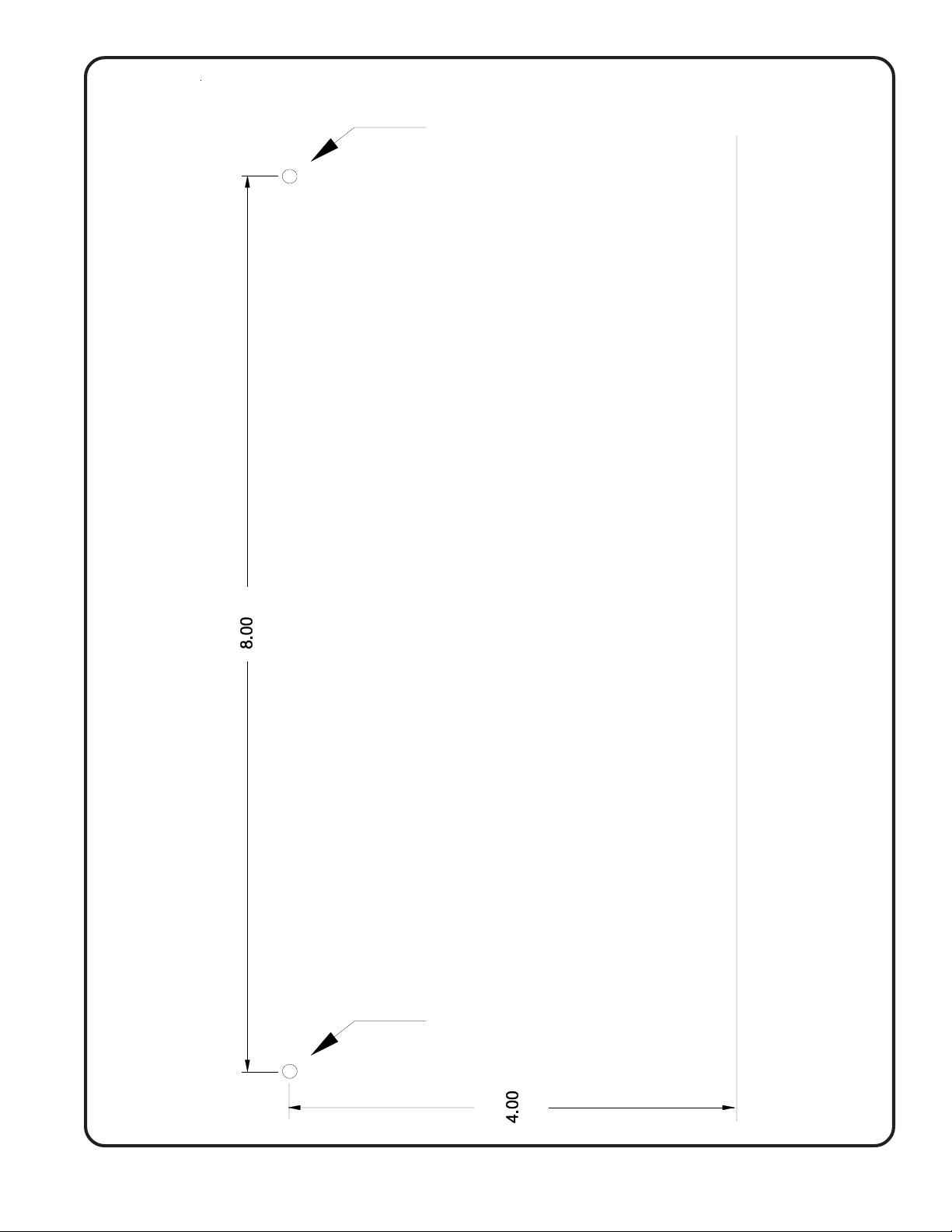
Figure 4—PM900 Control Unit
Mounting Template
Drill Here
THIS EDGE TO SIDE OF HOUSING
Copyright © TekTone Sound & Signal Mfg., Inc. All Rights Reserved.
THIS EDGE TO SIDE OF HOUSING
Drill Here
THIS EDGE TO SIDE OF HOUSING
IL573 Tek-ENTRY® Telephone Entry System Phone-Line Version Manual • 11
Page 16
OH192
Housing
Figure 5—Frame and Housing Installation
OF192
Frame
TE905A
Frame
Bracket
Vandal
Resistant
Screws
AM190D
Directory
TE Series Master Housing & Frame Chart
FRAMES FLUSH MOUNT HOUSING
Model# Width Cut-out Model # Overall Cut-out Overall Cut-out Depth
OF191 6-1/4" - OH191 4-3/8" 4-1/2" 17-1/8" 17-1/4" 3-1/2"
OF192 10 1/4" - OH192 8-3/8" 8-1/2" 17-1/8" 17-1/4" 3-1/2"
OF193 14-1/4" - OH193 12-3/8" 12-1/2" 17-1/8" 17-1/4" 3-1/2"
OF194 18-1/4" - OH194 16-3/8" 16-1/2" 17-1/8" 17-1/4" 3-1/2"
OF195 22-1/4" - OH195 20-3/8" 20-1/2" 17-1/8" 17-1/4" 3-1/2"
OF196 26-1/4" - OH196 24-3/8" 24-1/2" 17-1/8" 17-1/4" 3-1/2"
For more than 240 suites, contact factory for frame and housing information. Directories supplied separately.
Notes:
1. Refer to frame and housing chart for wall cut-out dimensions.
2. AM190D directory panels have 60 name capacity. For additional directories, size the frame and
housing accordingly. (Example: 1-TE905A + 2-AM190D would require an OF/OH193, 1-TE905A+3AM190D would require an OF/OH194, 1-TE905A+0-AM190D would require an OF/OH191.)
3. Flush mounting frame shown in diagram above.
4. Frame bracket supplied with OF192. Bracket is supplied with scrulox screws, but it is suggested you
use the spanner type vandal-resistant screws supplied with the TE905A. Use TekTone® driver
#HT007.
5. Refer to Figure 4—PM900 Control Unit Mounting Template to mount the PM900 Control Unit inside
the housing.
Wall Width Wall Height Wall
12 • IL573 Tek-ENTRY® Telephone Entry System Phone-Line Version Manual
Copyright © TekTone Sound & Signal Mfg., Inc. All Rights Reserved.
Page 17

Programming Worksheet ————————————————–
Building Address: ___________________________________________________________________________
___________________________________________________________________________
Date of Installation: ______________________ System Telephone Line #: _____________________
Installation Company: ___________________________________________________________________________
___________________________________________________________________________
Programming Instructions:
A. Enter “*” and the three-digit Master Code (see #3 below) on the keypad to access the programming menu.
B. Press the “1” key to scroll up, or press the “3” key to scroll down the menu screen to the desired function.
C. Press the “#” key to select the desired function when it is displayed on the screen.
D. Follow the displayed instructions to make the necessary changes.
E. Press the “*” key twice to end program mode.
Factory Default Programming:
Function Factory Default Programmed
1. Tenant Dial Codes Blank (4 digits) See Directory Worksheet
2. Keyless Entry Codes Blank (4 digits) See Directory Worksheet
3. Master Code * 1 2 3 * __ __ __
4. 7-, 10- or 11-Digit Programming 7 digits ______________________
5. Pulse or Tone Dialing DTMF (Tone) ______________________
6. Door Open Time 10 Seconds __ __ (0-99 sec)
7. Talk Time 60 Seconds __ __ (0–99 sec)
8. Night Service Disabled ______________________
9. Rotary Phones Disabled __ __ __
10. Guard Telephone Number Blank __ ( __ __ __ ) __ __ __ – __ __ __ __
Copyright © TekTone Sound & Signal Mfg., Inc. All Rights Reserved.
IL573 Tek-ENTRY® Telephone Entry System Phone-Line Version Manual • 13
Page 18

Tek-ENTRY® Telephone Entry System Directory Worksheet —
Suite # Tenant Name Telephone #
Tenant
Dial Code
Keyless
Entry Code
14 • IL573 Tek-ENTRY® Telephone Entry System Phone-Line Version Manual
Copyright © TekTone Sound & Signal Mfg., Inc. All Rights Reserved.
Page 19
Tek-ENTRY® Telephone Entry System Directory Worksheet —
Suite # Tenant Name Telephone #
Tenant
Dial Code
Keyless
Entry Code
Copyright © TekTone Sound & Signal Mfg., Inc. All Rights Reserved.
IL573 Tek-ENTRY® Telephone Entry System Phone-Line Version Manual • 15
Page 20

Tek-ENTRY® Telephone Entry System Directory Worksheet —
Suite # Tenant Name Telephone #
Tenant
Dial Code
Keyless
Entry Code
16 • IL573 Tek-ENTRY® Telephone Entry System Phone-Line Version Manual
Copyright © TekTone Sound & Signal Mfg., Inc. All Rights Reserved.
Page 21
Tek-ENTRY® Telephone Entry System Directory Worksheet —
Suite # Tenant Name Telephone #
Tenant
Dial Code
Keyless
Entry Code
Copyright © TekTone Sound & Signal Mfg., Inc. All Rights Reserved.
IL573 Tek-ENTRY® Telephone Entry System Phone-Line Version Manual • 17
Page 22

Tek-ENTRY® Telephone Entry System Directory Worksheet —
Suite # Tenant Name Telephone #
Tenant
Dial Code
Keyless
Entry Code
18 • IL573 Tek-ENTRY® Telephone Entry System Phone-Line Version Manual
Copyright © TekTone Sound & Signal Mfg., Inc. All Rights Reserved.
Page 23

Tek-ENTRY® Telephone Entry System Operating Instructions
A TekTone® Tek-ENTRY® Telephone Entry System has been installed in your building to
provide increased security for yourself and your family. The system provides communication
and entry control using your telephone.
Y our visitor will find your name and assigned dial code number on the directory near the T ek-
®
ENTRY
T elephone Entry System.
When the visitor enters your dial code number, the Tek-ENTRY® Telephone Entry System
will automatically ring your suite. You can answer from any telephone.
Answer the call and establish the identity of your visitor. The call will automatically cut off
after a preprogrammed time period.
If you want to allow your visitor to enter, simply dial or press “9” on your telephone. This will
unlock the entrance to your building or complex. You will hear a tone indicating the lock has
been released. After hearing the tone, you may hang up.
T o deny entry, simply hang up. Do not dial “9.”
If you are on the phone when a visitor calls you from the Tek-ENTRY
®
Telephone Entry
System, they will get a busy signal unless you have “call waiting” service assigned to your
telephone.
Optional Entry Code Use
If the box below is filled in, you have been assigned your own entry code. Entering this code
on the Tek-ENTRY® Telephone Entry System keypad will allow you to enter the building
without a key. When using this code, it is not necessary to pick up the handset. Press the “#”
key, and then the four -digit number. Your code will not appear on the display.
#
Sound & Signal Mfg., Inc.
Copyright © TekTone Sound & Signal Mfg., Inc. All Rights Reserved.
IL573 Tek-ENTRY® Telephone Entry System Phone-Line Version Manual • 19
Page 24

 Loading...