

Page 1

IL600
SECTION E
REV. 26 - 09/2002
Website:
www.tektone.net
Email:
Tek-DIGICARE
®
NC205 Nurse Call System
UL® Listed 1069
INSTALLATION INSTRUCTIONS
AND SERVICE MANUAL
For Technical Assistance:
1-800-332-6608
Technical Assistance Email:
277 Industrial Park Road
Franklin, NC 28734
(828) 524-9967
(800) 327-8466
Fax (828) 524-9968
4190 Fairview St., Unit B-8
Burlington, ON L7L 4Y8
Canada
(905) 333-0051
Fax (905) 333-0599
APPLICATION: The NC205 Tek-DIGICARE® Nurse Call System is a
microcontroller based system consisting of central equipment
cabinet(s) along with patient/duty/staff/emergency/code/presence
stations, dome/zone lights, and master stations.
The NC205 Series is designed for use in individual hospital wards,
nursing homes, and congregate living centers.
Copyright © TekTone Sound & Signal Mfg., Inc. All Rights Reserved.
Page 2

Operation, Installation and Service Manual
Copyright © 2002 TekTone® Sound & Signal Mfg., Inc., All rights reserved.
No part of this publication may be copied without the express written permission of TekTone® Sound & Signal Mfg., Inc. The
content of this manual is furnished for informational use only, is subject to change without notice, and should not be
construed as a commitment by TekTone® Sound & Signal Mfg., Inc. TekTone® Sound & Signal Mfg., Inc. assumes no
responsibility or liability for any errors or inaccuracies that may appear in this documentation.
TekTone, the TekTone logo, Tek-Call, Tek-Care, Tek-Check-In, Tek-Com, Tek-Digicare, Tek-Door, Tek-Entry III, TekGuard, Tek-Micro, Tek-Micro II, Tek-MMARS II, TekNIOS, TekNIOS II, Tek-Paging, Tek-Phone, Tek-Safe, Tek-Select II,
Tek-Sentry, Tek-Sound, Tek-Status, Tek-Trio and Tek-View are either registered trademarks or trademarks of TekTone
Sound & Signal Mfg., Inc. in the United States and/or other countries. All other trademarks are the property of their
respective owners.
®
ii • IL600 NC205 Tek-DIGICARE® Manual
Copyright © TekTone Sound & Signal Mfg., Inc. All Rights Reserved.
Page 3

TABLE OF CONTENTS
1.0 SYSTEM INTRODUCTION...................................................................................................... 1
A Word About Electrostatic Discharge.............................................................................................................................. 1
2.0 INSTALLATION PROCEDURE................................................................................................3
2.1 EQUIPMENT SUMMARIES......................................................................................................................................... 3
NC260B Central Equipment
NC262A Central Equipment Expander
PK261A Dome Light Power Supply
NC250 Master Station
NC230 Master Station
NC255 - 50 Station Master Expander
PM261A Selector Card
IR250 Standard Staff Station
IR251 Single/IR252 Dual Standard Patient Stations
IR253 Standard Pull Cord Patient Station
IR254 Enhanced Staff Station
IR255 Single/IR256 Dual Enhanced Patient Stations
IR257 Single/IR258 Dual Enhanced Patient Stations
IR259 Enhanced Multipurpose Station
IR019C Speaker/Microphone Station
IR260A Duty Station
LI381 Single/LI382 Dual Corridor Dome/Zone Lights
LI383/LI387 Corridor Dome/Zone Lights
LI388A Corridor Zone Light
SF100C Visual Station
SF101C Visual Station
BA002K Battery Kit
SF337C Pull Cord Shower/Emergency Station
SF340B Pull Cord Emergency Station
SF341B Code Call Station
SF250 Staff Presence Station
Call Cords
2.2 EQUIPMENT LOCATION............................................................................................................................................. 5
NC260B Central Equipment
NC262A Central Equipment Expander
PK261A Dome Light Power Supply
PM261A Selector Card
NC250/NC230 Master Stations and NC255 Master Station Expander
IR Series Stations
LI Series Corridor Dome/Zone Lights
SF Series Peripheral Stations
Call Cords/Pillow Speakers
2.3 WIRING INSTALLATION............................................................................................................................................. 6
NC260B Central Equipment and NC262A Central Equipment Expander
PK261A Dome Light Power Supply
NC250/NC230 Master Station
IR Series Stations
LI Series Corridor Dome/Zone Lights
SF Series Peripheral Stations
Copyright © TekTone Sound & Signal Mfg., Inc. All Rights Reserved.
IL600 NC205 Tek-DIGICARE® Manual • iii
Page 4

2.4 HOUSING INSTALLATION................................................................................................................................ 7
NC260B Central Equipment and NC262A Central Equipment Expander
PK261A Dome Light Power Supply
NC250/NC230 Master Stations and NC255 Master Station Expander
IR Series Stations
LI Series Corridor Dome/Zone Lights
SF Series Peripheral Stations
2.5 WIRE CHECK-OUT........................................................................................................................................................ 8
2.6 WIRE CONNECTION..................................................................................................................................................... 8
NC260B Central Equipment
NC262A Central Equipment Expander
PK261A Dome Light Power Supply
NC250/NC230 Master Stations
NC255 Master Station Expanders
IR Series Stations
LI Series Corridor Dome/Zone Lights
SF Series Peripheral Stations
2.7 VOLUME SETTINGS & ADJUSTMENTS.................................................................................................................. 10
PM261A Selector Cards
NC250/NC230 Master Station
IR254-IR259 Enhanced Patient Stations
IR260A Duty Station
LI388A Corridor Zone Light
2.8 CONNECTIONS CHECK-OUT...................................................................................................................................... 11
2.9 NC205 INSTALLATION AND POWER-UP GUIDELINES........................................................................................11
3.0 SYSTEM EQUIPMENT DESCRIPTIONS................................................................................ 17
3.1 NC250/NC230 MASTER STATION..............................................................................................................................17
Function Buttons
Numerical Keys
Alpha Keys
Station Selector Buttons
Power ON LED
Fault LED
Priority LED’S - GREEN, AMBER, and RED
DIP Switch
Handset
Hook Switch
Volume Control
Speaker
Microphone
Tray
3.2 NC255 MASTER EXPANDER....................................................................................................................................... 19
Station Selector Buttons
DIP Switch
3.3 MASTER STATION & EXPANDER DISPLAYS........................................................................................................ 19
Call Location
Fire Calls
Code Calls
Emergency/Bath/Priority/Cord Out Calls
Personal Attention and Routine Calls
System Fault Indications
iv • IL600 NC205 Tek-DIGICARE® Manual
Copyright © TekTone Sound & Signal Mfg., Inc. All Rights Reserved.
Page 5

3.4 PATIENT STATIONS............................................................................................................................................. 20
3.4-1 IR251/IR252 Standard Stations
Reset Button/In-Use LED
Call-Placed LED
Call Cord Receptacle
3.4-2 IR255-IR258 Enhanced Stations
Reset Button/In-Use LED
Call-Placed LED
Call Cord Receptacle
3.5 IR250 STANDARD/IR254 ENHANCED STAFF AND IR260A DUTY STATIONS............................................... 21
Reset Button/In-Use LED
Call Button/Call-Placed LED
IR260A Duty Station Special Features
3.6 IR253 STANDARD PULL CORD PATIENT STATION............................................................................................. 21
Reset Button/In-Use LED
Call-Placed LED
Pull Cord
3.7 IR259 ENHANCED MULTIPURPOSE STATION....................................................................................................... 22
3.8 SF100C VISUAL STATION............................................................................................................................................22
Call-Placed LED
Call Cord Receptacle
Cancel Button
3.9 SF101C VISUAL STATION............................................................................................................................................22
Call-Placed LED/ Push button
Cancel Button
3.10 SF250 STAFF PRESENCE STATION........................................................................................................................... 23
Staff Registration Button
Staff Registration LED
3.11 SF337C/SF340B PULL CORD SHOWER/EMERGENCY STATION......................................................................... 23
Emergency Pull Down Lever
Call-Placed LED
3.12 SF341B CODE CALL STATION................................................................................................................................... 23
Call/Reset Lever
Call-Placed LED
3.13 LI SERIES CORRIDOR DOME/ZONE LIGHTS.......................................................................................................... 24
Dome Lights
Zone Lights
Copyright © TekTone Sound & Signal Mfg., Inc. All Rights Reserved.
IL600 NC205 Tek-DIGICARE® Manual • v
Page 6

4.0 OPERATIONAL PROCEDURES.............................................................................................. 25
4.1 MASTER STATION and EXPANDERS............................................................................................................... 25
4.1-1 Calling
A. To answer a call
B. To place a call
C. To cancel a call
D. To upgrade calls in progress
4.1-2 Staff Service
A. To request staff service
B. To cancel a staff service request or staff presence
C. To view staff status
4.1-3 Paging
A. To page a specific zone
B. To page master preset zones
C. To page all stations on the system (ALL CALL)
D. To page a staff member
E. To discontinue paging
4.1-4 Follower Functions
A. To follow a staff member
B. To follow to a specific room
C. To discontinue the follower function
4.1-5 Station Functions
A. To view a station’s zone assignments and status
B. To view and/or change stations in privacy mode
C. To change the priority status of a station
D. To view the priority status of stations
4.1-6 Master Functions
A. To enable room monitoring
B. To view the master’s zone assignments and status
4.2 IR SERIES STATIONS.................................................................................................................................................... 27
4.2-1 IR251/IR252 Standard and IR255/IR256 Enhanced Patient Stations
A. To place a call
B. To cancel a call
4.2-2 IR257/IR258 Enhanced Patient Stations
A. To place a call
B. To control the television
C. To cancel a call
4.2-3 IR250 Standard and IR254 Enhanced Staff Stations
A. To place a call
B. To cancel a call
4.2-4 IR253 Standard Pull Cord Station
A. To place a call
B. To cancel a call
4.2-5 IR259 Enhanced Multipurpose Station
A. To place a call
B. To cancel a call
4.2-6 IR260A Duty Station
A. To place a call
B. To adjust the announcement volume
C. To cancel a call
4.3 SF SERIES PERIPHERAL STATIONS..........................................................................................................................27
4.3-1 SF100C Visual Station
A. To place a call
B. To cancel a call
vi • IL600 NC205 Tek-DIGICARE® Manual
Copyright © TekTone Sound & Signal Mfg., Inc. All Rights Reserved.
Page 7

4.3-2 SF101C Visual Station
A. To place a call
B. To cancel a call
4.3-3 SF250 Staff Presence Station
A. To register staff presence
B. To clear staff presence
C. To clear a staff request at a station
4.3-4
SF337C/SF340B Pull Cord Shower/Emergency Station
A. To place a call
B. To cancel a call
4.3-5 SF341B Code Call Station
A. To place a call
B. To cancel a call
5.0 SYSTEM CONFIGURATION/PROGRAMMING......................................................................29
5.1 MASTER STATIONS..................................................................................................................................................... 29
5.1-1 Entering the Programming Mode
A. To select zone presets
B. To program master zones
C. To program master status
D. To view station fault list
5.1-2 Exiting the Programming Mode
5.2 PATIENT STATIONS..................................................................................................................................................... 30
5.2-1 Entering the Programming Mode
A. To assign zones
B. To program station status
C. To program a selector key for master-to-master communication
5.2-2 Exiting the Programming Mode
5.3 MASTER KEY PROGRAMMING/CONFIGURATION............................................................................................. 31
5.3-1 Entering the Programming Mode
A. To reset a master station to default values (erase flash memory)
B. To add an expansion keypad
C. To make a master “non-square”
D. To custom configure a specific selector button
E. To set the system time
5.3-2 Exiting the Programming Mode
5.4 EQUIPMENT RESET PROCEDURES.......................................................................................................................... 32
5.4-1 Central Equipment
A. To reset the central equipment
B. To reset the flash memory
C. To disable system programming from masters (programming lock)
5.4-2 Master Stations
A. To reset a master
B. To erase flash memory
5.5 EXPANDING/UPGRADING THE SYSTEM................................................................................................................32
5.5-1 Adding Central Equipment Expander
5.5-2 Adding Battery Backup
5.5-3 Adding Master Stations
5.5-4 Adding Master Expanders
5.5-5 Adding Remote Stations
5.5-6 Adding Peripheral Devices
Copyright © TekTone Sound & Signal Mfg., Inc. All Rights Reserved.
IL600 NC205 Tek-DIGICARE® Manual • vii
Page 8

5.6 VIEWING SYSTEM INFORMATION.......................................................................................................................... 33
5.6-1 Status Display Pages
A. Privacy display
B. Priority display
C. Staff display
5.6-2 Faults
A. Master station fault
B. Code circuit fault
C. Station fault
6.0 SYSTEM MAINTENANCE INSTRUCTIONS...........................................................................35
6.1 NC260B CENTRAL EQUIPMENT and NC262A CENTRAL EQUIPMENT EXPANDER ............................... 35
6.2 PK261A DOME LIGHT POWER SUPPLY....................................................................................................................35
6.3 NC250/NC230 MASTER STATIONS and NC255 MASTER STATION EXPANDER........................................... 35
6.3-1 Defective Handset/Cord Replacement
6.3-2 8 PIN Modular Cord
6.4 IR SERIES STATIONS.................................................................................................................................................... 35
6.4-1 Defective Pillow Speaker Replacement
6.4-2 Defective Call Cord Replacement
6.5 SF SERIES STATIONS................................................................................................................................................... 35
6.6 LI SERIES DOME/ZONE LIGHTS................................................................................................................................ 35
6.6-1 Defective Lamp Replacement
6.7 REPLACEMENTS PARTS............................................................................................................................................. 36
7.0 TEST INSTRUCTIONS............................................................................................................. 37
7.1 SYSTEM INSPECTION.................................................................................................................................................. 37
7.1-1 Basic Wiring Check
7.1-2 Test Setup
7.1-3 Viewing System Faults
7.2 CENTRAL EQUIPMENT AND EXPANDERS............................................................................................................ 37
7.2-1 NC260B Central Equipment
7.2-2 NC262A Central Equipment Expander
7.2-3 PK261A Dome Light Power Supply
7.2-4 PM261A Selector Card
7.3 MASTER STATIONS AND EXPANDERS..................................................................................................................38
7.3-1 Basic Communications
7.3-2 Staff Functions
7.3-3 Paging Functions
7.3-4 Follower Functions
7.3-5 Priority Upgrade
7.3-6 Privacy Functions
7.4 REMOTE STATIONS..................................................................................................................................................... 41
7.5 SF SERIES PERIPHERAL DEVICES............................................................................................................................ 42
7.6 LI SERIES PERIPHERAL DEVICES.............................................................................................................................. 43
viii • IL600 NC205 Tek-DIGICARE® Manual
Copyright © TekTone Sound & Signal Mfg., Inc. All Rights Reserved.
Page 9

APPENDIX
Appendix 1.0 ...................................................................................................................................................
NC260B Communications Mode
1.1 General ................................................................................................................................ 44
1.2 Local Operation .................................................................................................................... 44
1.3 Remote Operation ................................................................................................................. 44
1.4 Communication Software ...................................................................................................... 45
Appendix 2.0 System Operation
2.1 General .................................................................................................................................. 46
2.2 Error Codes and Messages .................................................................................................. 48
WIRING DIAGRAMS
NL# Description Reference Section #
NL205-A NC205 Block Wiring Diagram w/Enhanced Stations and Dome Light
Conduit Runs ..................................................................................................................... 2.3, 2.6
NL205-B NC205 Block Wiring Diagram w/Standard Stations and Dome Light
Conduit Runs ..................................................................................................................... 2.3, 2.6
NL205-C NC205 Block Wiring Diagram w/Enhanced Stations and Station Conduit Runs ................ 2.3, 2.6
NL205-D NC205 Block Wiring Diagram w/Standard Stations and Station Conduit Runs ................. 2.3, 2.6
NL205-E NC260B Central Equipment Wiring ....................................................................................... 2.6
NL205-F NC262A Central Equipment Expansion Wiring ..................................................................... 2.6
NL205-G NC250/NC230 Master Stations & NC255 Master Station Expander ...................................... 2.6
NL205-H Maximum Wiring Distances and Standard Wire Colors ............................................... 2.2, 2.3, 2.5, 2.6
NL205-H -1 Maximum Wiring Distances and Cable Configuration ................................................. 2.2, 2.3, 2.5, 2.6
NL205-H -2 Maximum Wiring Distances and Central Equipment Configuration ............................. 2.2, 2.3, 2.5, 2.6
NL205-I IR250-IR253 Station Wiring (includes SF Series and LI Series Peripherals) .......................... 2.6
NL205-J IR250-IR253 Station Wiring (reduced wiring scheme with Emergency Peripheral) ................ 2.6
NL205-K IR254-IR256 Enhanced Station Wiring (includes SF and LI Peripherals)............................... 2.6
NL205-L IR254-IR256 Enhanced Station Wiring in Multiples (includes SF and LI Peripherals) .......... 2.6
NL205-M IR257 and IR258 Enhanced Station Wiring ............................................................................ 2.6
NL205-N IR260A Duty Station and LI388A Zone Light Wiring ........................................................... 2.6
NL205-O IR259 Enhanced Station Wiring ......................................................................................... 2.6, 3.7
NL205-P Stand Alone use of SF Series Peripherals (includes fire or smoke contacts) .................... 2.6, 3.10
NL205-P1 Visual Station with peripherals (includes emergency station and smoke contacts) ........2.6, 3.8, 3.9
NL205-Q NC260B/NC262A 120 VAC Connection Diagram ................................................................... 2.6
NL205-R PK261A Wiring Diagram ....................................................................................................... 2.6
NL205-S Battery Kit Installation .......................................................................................................... 2.6
Copyright © TekTone Sound & Signal Mfg., Inc. All Rights Reserved.
IL600 NC205 Tek-DIGICARE® Manual • ix
Page 10

FIGURES
Fig. # Description Page #
1 IH352 Ring and IH353 Housing Installation ........................................................................... 7
2 IH357 Ring and IH358 Housing Installation ........................................................................... 7
3 Master Station Cable Assembly Wiring ................................................................................. 9
4 PM261A Selector Card ........................................................................................................... 9
5 Master Station Controls ......................................................................................................... 10
6 Code Fault Jumper ................................................................................................................. 11
7 IR260A Duty Station .............................................................................................................. 11
8 NC250 Master ........................................................................................................................ 17
9 NC250/NC230 Master DIP Switch Controls ........................................................................... 18
10 NC255 Master Expander .........................................................................................................19
11 IR251/IR252 Standard and IR255/IR256/IR257/IR258 Enhanced Patient Stations ..................20
12 IR250 Standard/IR254 Enhanced Staff and IR260A Duty Stations......................................... 21
13 IR253 Standard Pull Cord Patient Station ...............................................................................21
14 IR259 Enhanced Multipurpose Station .................................................................................. 22
15 SF100C Visual Station ............................................................................................................ 22
16 SF101C Visual Station ............................................................................................................ 22
17 SF250 Staff Presence Station..................................................................................................23
18 SF337C/SF340B Pull Cord Shower/Emergency Station ..........................................................23
19 SF341B Code Call Station .......................................................................................................23
20 LI381/LI382/LI383 Corridor Dome/Zone Lights ......................................................................24
21 LI387/LI388A Corridor Dome/Zone Lights .............................................................................24
22 NC250/NC230 Programming Inserts ....................................................................................... 29
23 NC250/NC230 Master DIP Switch Controls ...........................................................................31
24 NC260B Null Modem Cable ....................................................................................................44
25 NC260B Communications Mode Help Screen ........................................................................ 46
26 NC260B Dip Switch Settings .................................................................................................. 47
x • IL600 NC205 Tek-DIGICARE® Manual
Copyright © TekTone Sound & Signal Mfg., Inc. All Rights Reserved.
Page 11

1.0 SYSTEM INTRODUCTION
The NC205 Nurse Call System is a supervised, microcontroller
based system that provides a complete range of two-way
audio and visual signaling for staff-to-patient and staff-tostaff communications.
The NC205 Nurse Call System is complemented by a wide
range of bedside stations and peripherals:
• duty and staff stations
• single and dual patient stations
• dome and zone corridor lights
The NC250/NC230 Master Stations and NC255 Master
Expander make up the control console where patient calls are
registered and displayed. The control consoles provide
facilities for:
• locating and dispatching staff personnel
• code, emergency, bath, and
staff presence peripherals
The features of the master stations, bedside stations, and
peripherals are discussed in greater detail in Section 3.0System Equipment Description.
• managing patient priority and privacy
• monitoring all emergency situations
• performing system configurations
• monitoring code, communication, station,
and central equipment faults.
Simplified wiring and plug-in design provide ease of
installation in new and/or existing facilities. Modular circuitry
and interchangeable room stations permit the system to be
easily upgraded and expanded at anytime.
A WORD ABOUT ELECTROSTATIC DISCHARGE
What Is It? Static electricity is a result of triboelectric charging of two dissimilar nonconductive materials rubbed together, like rubbing your
feet on a carpet on a cold winter day, or in a dry climate. The resulting charge is detected when you reach out to touch a doorknob or some
other metallic object. The resulting discharge may be only startling, or in severe cases it may even be painful. The actual electrical charge
is dependent on the materials rubbed together, humidity, rate of separation and other factors.
What Can It Do? While this effect may be disturbing to humans, the effect on electronic equipment is often more serious, ranging from
disrupting the operation to actual damage of the components. These effects result from the high voltages that may be developed. The simple
act of walking across a carpet may develop as much as 30,000 volts; changing a bed sheet may create a charge of 100,000 volts or more. Such
voltages readily cause arcing (the spark you see in the dark when you grab the doorknob, after walking across the carpet, etc.). The arcing
is evidence of a discharge path. Due to the high voltage involved, the discharge current can jump to any nearby metallic object. If the discharge
is to or through an electronic device, such as the nurse call system, the operation of the device may be affected. If the discharge current passes
through internal components, these components may be damaged or their operation degraded.
What Can We Do About It? The manufacturer of the nurse call equipment has already taken steps to protect the equipment from electrostatic
discharge (ESD) effects. However, since the cause of the problem is not in the equipment, but in the environment, further measures are required
of the installer and the user to achieve complete protection.
What The Installer Can Do: In humid climates or in places where the relative humidity is kept at 65% or greater, there will likely be
few problems with ESD. Where problems may occur, the following measures can be taken.
1. Ground all exposed metal surfaces, such as patient station panels, etc. Grounding should be to a #14 or larger conductor.
2. Install nurse call system wiring in metal conduit. This conduit may also be used to ground panels. The conduit must be electrically
continuous and be grounded.
3. Use shielded wire in cable for nurse call system station- to-station wiring. The use of open conductors invites inductive coupling of
discharge currents which can cause the same problems as direct discharge currents.
4. Ground your body before handling system components. This can be done using a wrist strap, or simply by contacting a grounded surface.
Use caution to avoid hazardous voltages while grounded.
What The User Can Do: The most common generation of ESD in hospitals is due to changing linen on hospital beds while the patient
call cord or pillow speaker is still connected to the nurse call system. The following precautions will help.
1. Remove the call cord or pillow speaker from the bed before changing. It will be necessary for the nursing staff to discharge themselves
by contacting a grounded metal object before placing the call cord or pillow speaker back on the bed; otherwise, a spark will jump to
the nurse call equipment, causing the very damage they are trying to avoid. (To avoid a shock while discharging static electricity on
the body, hold a metal object, such as a key, and use that object to contact the grounded surface.)
2. Ground the bed and use antistatic mattress covers in contact with the bed frame. For safety, it may be desirable to make the ground
connection through a 1 megohm resistor. Nursing staff must be trained to disconnect and reconnect the ground whenever beds have
to be moved.
3. Use grounded appliances and equipment near nurse call systems. The use of approved electrical equipment will usually take care of
this.
This information is provided to make you aware of ESD problems so that precautions may be taken to avoid damage and disruption of system
operation.
Copyright © TekTone Sound & Signal Mfg., Inc. All Rights Reserved.
IL600 NC205 Tek-DIGICARE® Manual • 1
Page 12

2 • IL600 NC205 Tek-DIGICARE® Manual
Copyright © TekTone Sound & Signal Mfg., Inc. All Rights Reserved.
Page 13

2.0 INSTALLATION PROCEDURE
Read the following instructions concerning system
equipment and determine installation methods before
proceeding. Also review installation and power-up
guidelines, section 2.9, when equipment has been received.
A. Determine equipment locations.
B. Install wiring.
C. Install housings.
D. Check wires.
E. Connect equipment.
F. Check connections.
G. Test system.
H. Configure system.
I. Train system operators.
2.1 EQUIPMENT SUMMARIES
NC260B Central Equipment
The NC260B provides microcontroller, signaling, and power
circuitry (except in applications requiring the PK261A) to
operate the NC205 Nurse Call System. The central equipment
may interface with up to four NC250/NC230 Master Stations
and their NC255 Master Expanders, and one NC262A Central
Equipment Expander. The central equipment consists of
microcontroller, memory, interface, and power supply circuits.
All outputs are protected by self-resetting current limiting
circuitry. All equipment is completely contained in a hinged
surface mount cabinet. A recommended backup battery kit is
available.
NC262A Central Equipment Expander
The NC262A provides the additional circuitry necessary to
interface with the NC260B Central Equipment and two
additional PM261A Selector Cards. It also includes an
additional power supply. This enables the system to be
expanded to 128 remote stations.
NOTE: A 128 remote station (maximum) system would
require:
1 - NC260B with 2 - PM261A’s
1 - NC262A with 2 - PM261A’s
PK261A Dome Light Power Supply
The PK261A Dome Light Power Supply provides power for
dome lights connected to enhanced patients stations (IR254-
259). Connections to dome light field wiring are provided via
a plug-on connector.
NC250 Master Station
The NC250 utilizes digital technology to provide
communications, fault monitoring, and programming for the
NC205 Nurse Call System. The master station consists of a
handset, volume control, speaker, microphone, 8 color-coded
function buttons, 50 individual room selector buttons, and
LED’s for call priority, power, and fault. All LED’s and buttons
are on a spill-proof membrane switch assembly.
NC230 Master Station
The NC230 has the same functionality as the NC250 but
provides 30 individual room selector buttons with LED’s.
NC255 - 50 Station Master Expander
The NC255 provides the additional circuitry and buttons to
expand the capacity of a master station by 50 rooms. Call
LED’s and selector buttons are on a spill-proof membrane
switch assembly.
PM261A Selector Card
The PM261A provides connection points for up to 32 stations.
Integrated digital and analog technology provide for reliable
communications between system components. Each NC260B/
NC262A is capable of supporting two PM261A Selector Cards
to provide access for up to 64 IR Series Remote Stations.
IR250 Standard Staff Station
The IR250 provides reliable two-way, hands-free
communication between the nurse master station and any
location where staff members may need to originate calls or
where cord sets are not required. It may also function as a
push button patient station. The station contains a
combination yellow “CALL-PLACED” indicator and “CALL”
button, a combination red “IN-USE” indicator and “RESET”
button, and a speaker/microphone. The IR250 is mounted on
an attractive flame retardant type ABS plastic faceplate. The
IR250 operates with single and dual lamp dome lights (LI381/
LI382), and has inputs for “BATH/EMERGENCY” and “FIRE.”
IR251 Single/IR252 Dual Standard Patient Stations
The IR251/IR252 stations include yellow “CALL-PLACED”
indicator(s), patient call cord receptacle(s), a combination
red “IN-USE” indicator and “RESET” button, and a speaker/
microphone. The stations use 1/4" phone jack(s) and are
mounted on attractive flame retardant type ABS plastic
faceplates. Both provide outputs for single/dual light dome
lights (LI381/LI382) and two peripheral devices
(“EMERGENCY” and “FIRE”).
IR253 Standard Pull Cord Patient Station
The IR253 has all the same functions as the IR251/IR252
Stations, but provides a patient pull cord instead of call cord
jack. The IR253 consists of a yellow “CALL-PLACED”
indicator, a combination red “IN-USE” indicator and “RESET”
button, and a speaker/microphone. The IR253 is mounted on
an attractive flame retardant type ABS plastic faceplate, and
provides outputs for single and dual lamp dome lights (LI381/
LI382) and two peripheral devices (“EMERGENCY” and
“FIRE”).
Copyright © TekTone Sound & Signal Mfg., Inc. All Rights Reserved.
IL600 NC205 Tek-DIGICARE® Manual • 3
Page 14

IR254 Enhanced Staff Station
The IR254 provides reliable two-way, hands-free
communication between the nurse master station and any
location where staff members may need to originate calls or
where cord sets are not required. It may also function as a
push button patient station. The station has a combination
yellow “CALL-PLACED” indicator and “CALL” button, a
combination red “IN-USE” indicator and “RESET” button,
and a speaker/microphone. The IR254 is mounted on an
attractive flame retardant type ABS plastic faceplate. The
IR254 includes supervision circuitry for code station and
associated wiring, additional outputs for a three lamp (LI383)
or four lamp dome light (LI387), and additional inputs for
multiple peripheral devices. Power and select wires are
supervised by central equipment.
IR255 Single/IR256 Dual Enhanced Patient Stations
The IR255/IR256 have the same basic functionality as the
IR251/IR252, but include microcontroller and supervision
circuitry for code station and associated wiring, to interface
with multiple peripheral devices. Both stations provide
outputs for three lamp (LI383) or four lamp dome lights (LI387).
Power and select wires are supervised by central equipment.
IR257 Single/IR258 Dual Enhanced Patient Stations
The IR257/IR258 have all the same functions as the IR255/
IR256 but use 8-pin modular jack receptacle(s) to interface
with TekTone®’s SF301P Pillow Speakers or SF311/SF312
Series Call Cords.
IR259 Enhanced Multipurpose Station
The IR259 is patterned after the IR254, but has no user
controls. The IR259 is mounted on an attractive flame
retardant type ABS plastic blank faceplate. It provides
connections for external call and reset buttons, “CALL-
PLACED” and “IN-USE” indicators, and an external speaker/
microphone.
IR019C Speaker/Microphone Station
The IR019C provides audio communication capabilities when
used in conjunction with the IR259 Enhanced Multipurpose
Station and features a durable stainless steel faceplate.
IR260A Duty Station
The IR260A has all of the features and functions of the IR250,
but includes an “EMERGENCY” LED indicator and
microcontroller circuitry to display call information from
specific zones on associated zone lights (see descriptions
below). The IR260A also provides remote tone annunciation
of calls placed from any one or all of eight programmable
zones. Note: NC205 System is limited to 8 duty devices if the
PK261A Dome Lamp Power Supply is not used. These duty
devices may be LI388A or IR260A with dome lamps, in any
combination, not to exceed 8.
LI381 Single/LI382 Dual Corridor Dome/Zone Lights
The LI381/LI382 provides visual indication of calls originating
from patient, staff, bath, and stand alone stations. Low priority
calls are indicated by a white lamp. The LI382 provides an
additional lamp (red) for indication of higher priority calls.
The LI381/LI382 may also be used as zone lights when used
with an IR260A Duty Station but will only display those calls
associated with one or two lamps.
LI383/LI387 Corridor Dome/Zone Lights
The LI383/LI387 provides visual indication of calls originating
from patient, staff, and duty stations. The LI387 also provides
visual indication of calls originating from code call stations.
The LI383 consists of three incandescent lamps (red, green,
and white) covered by a single polystyrene lens. The LI387
consists of four incandescent lamps covered by translucent
polycarbonate (red, green, and blue) and polystyrene (white)
lenses mounted on an attractive ABS plastic base. Call priority
and staff presence are indicated by various flash rates applied
to the appropriate lamp(s). The LI387 functions as a zone
light when used with the IR260A Duty Station. The LI383 will
also function as a zone light when used with the IR260A
Duty Station but will only display calls that are associated
with one, two, or three lamps.
LI388A Corridor Zone Light
The LI388A is identical in appearance to the LI387, but
contains microcontroller and support circuitry to display call
priority indications from any or all of eight programmable
zones. The LI388A serves the same functions as an LI387
that is connected to an IR260A. Note: NC205 System is limited
to 8 duty devices if the PK261A Dome Lamp Power Supply is
not used. These duty devices may be LI388A or IR260A with
dome lamps, in any combination, not to exceed 8.
SF100C Visual Station
The SF100C is used to operate “ROUTINE” signals. The
station consists of an attractive flame retardant type ABS
plastic faceplate, a yellow “CALL-PLACED” indicator, a
“CANCEL” button, and a patient call cord receptacle (1/4"
phone jack). The SF100C is a stand-alone device.
SF101C Visual Station
The SF101C is used to operate “ROUTINE” signals. The
station consists of an attractive flame retardant type ABS
plastic faceplate, an amber “CALL-PLACED” indicator/push
button, and a “CANCEL” push button. The SF101C is a standalone device.
BA002K Battery Kit
The BA002K Kit provides battery backup for NC260B CE or
NC262A CEE. The kit includes two BA001 Batteries
(12 VDC, 2.0 AH) and connection harness.
4 • IL600 NC205 Tek-DIGICARE® Manual
Copyright © TekTone Sound & Signal Mfg., Inc. All Rights Reserved.
Page 15

SF337C Pull Cord Shower/Emergency Station
The SF337C is used to operate “BATH/EMERGENCY”
signals. The station consists of an attractive flame retardant
type ABS plastic faceplate, a red pull down lever, 7' nylon
cord with pendant, mounting screws, connector, a red “CALL-
PLACED” indicator, and electronic circuitry mounted to the
back of the faceplate. The SF337C is waterproof, when
mounted correctly, and is provided with a white rubber gasket,
mounting screws with “O” rings, and a circuit board with
reed switches.
SF340B Pull Cord Emergency Station
The SF340B is used to operate “BATH/EMERGENCY”
signals. The station consists of an attractive flame retardant
type ABS plastic faceplate, a red pull down lever, 7' nylon
cord with pendant, mounting screws, connector, a red “CALL-
PLACED” indicator, and electronic circuitry with a DPDT
switch mounted to the back of the faceplate.
SF341B Code Call Station
The SF341B is used to initiate “CODE” signals and is
monitored for fault conditions by IR254-259 Enhanced Patient
Stations. The SF341B consists of an attractive flame retardant
type ABS plastic faceplate, a blue pull down lever, a 7' nylon
cord with pendant, and mounting screws. A circuit board
with a DPDT switch, connectors, a red “CALL-PLACED”
indicator, and electronic circuitry is mounted to the back of
the faceplate.
SF250 Staff Presence Station
The SF250 provides push button registration of staff members
at remote locations when used with IR254-IR259 Enhanced
Patient Stations. The SF250 may also be used to transfer staff
follower features from one room to another. The station’s
circuitry is mounted on an attractive flame retardant type
ABS plastic faceplate and contains a push button and a green
LED indicator.
2.2 EQUIPMENT LOCATION
Locate NC205 System equipment in accordance with the
following information. The installation of all system
equipment must meet the requirements of the National
Electrical Code, ANSI/NFPA #70, current edition. Do not
locate or install NC205 System components in or near areas
of high humidity, static electricity, radiation, or heat.
NOTE: Please observe the maximum wiring distance per
NL205-H.
NC260B Central Equipment
The central equipment should be located in an accessible
area near a dedicated AC source, preferably central to the
associated master stations. For optimum operation, the central
equipment should be located in an area with an operating
temperature of approximately 26°C with 70-80% relative
humidity. Equipment should be accessible to a good local
earth ground using a minimum of #14 gauge wire. Location
should have convenient cable runs to the master and patient
stations. The central equipment may be wall mounted (surface
or recessed). A battery backup kit is recommended and should
be located within the central equipment.
NC262A Central Equipment Expander
The central equipment expander should be located in an
accessible area near a dedicated AC source. For optimum
operation, the central equipment expander should be located
in an area with an operating temperature of approximately
26°C with 70-80% relative humidity. Equipment should be
within 18 feet of the NC260B. The location should have
convenient cable runs to the central equipment and patient
stations. The central equipment expanders may be wall
mounted (surface or recessed). A battery backup kit is
recommended and should be located within the NC262A
Expander cabinet.
Call Cords
For use with IR251/IR252/IR255/IR256 and SF100C :
SF301 - Push button with 7' cord
SF301G - Geriatric push button call cord
SF301/10 - Push button with 10' cord
SF302 - Dual push button with 7' cords
SF302G - Geriatric dual push button call cord
SF302/10 - Dual push button with 10' cords
For use with IR257/IR258 :
SF301P Series - Pillow speaker
SF311 - Push button cord w/modular jack
SF311G - Geriatric/oxygen call cord
SF312 - Dual push button cords w/modular
jack
SF312G - Geriatric/oxygen dual call cords
Copyright © TekTone Sound & Signal Mfg., Inc. All Rights Reserved.
PK261A Dome Light Power Supply
The dome light power supply should be located in an
accessible area near a dedicated AC source. For optimum
operation, the dome light power supply should be located in
an area with an operating temperature of approximately 26°C
with 70-80% relative humidity. Equipment should be accessible
to the NC260B. Location should have convenient cable runs
to the central equipment and patient stations. The dome light
power supply may be wall mounted (surface or recessed).
PM261A Selector Card
The selector cards are mounted inside the NC260B Central
Equipment and the NC262A Central Equipment Expander.
IL600 NC205 Tek-DIGICARE® Manual • 5
Page 16

NC250/NC230 Master Stations and NC255 Master Station
Expander
The master stations and expanders should be located on a
desk or countertop within easy reach of operating personnel.
Each master station is provided with 7' of cable and an 8
conductor modular connector. The expander(s) are provided
with 1.3' of cable and an 8 conductor modular connector for
connection to the masters. The master station(s) should be
located within easy reach of the modular wall plate (TekTone
PL467) for cable termination. Locate the wall plate on a single
gang ring or box. The operating temperature range of 10°C 40°C should not be exceeded.
IR Series Stations
The patient stations should be located where convenient for
operation, most commonly at the head of the patient’s bed.
The operating temperature range of 10°C - 40°C should not
be exceeded.
The IR250/IR254 Staff Stations should be located where
convenient for operation in areas such as utility rooms, exam
rooms, kitchens, and wherever staff members may need to
originate calls. The IR250/IR254 may also be used as patient
stations in rooms where cord sets are not required.
The IR259 Enhanced Multipurpose Station should be
centrally located in regard to the remotely mounted initiation
devices (switches, contact closures, loudspeakers, or other
signal-originating equipment) with which it is used. No
controls are provided.
The IR019C Speaker/Microphone Station should be located
where audible in conjunction with the IR259. The IR019C is
designed for use in high security areas, such as psychiatric
wards. It is flush mounted, normally in the ceiling or out of
the patient’s reach.
The IR260A Duty Station should be located where convenient
for operation in areas such as utility and exam rooms, or
where a nurse may perform a function out of hearing or sight
of the NC250/NC230 Master Station.
LI Series Corridor Dome/Zone Lights
The dome lights should be located in the corridor above or
beside the door of the associated room. The location should
provide unobstructed visibility of the corridor light in both
directions. The zone lights should be located in the corridor
area nearest the nurses central monitoring station.
SF Series Peripheral Stations
The SF100C or SF101C Visual Station should be located where
convenient for operation, most commonly at the head of the
patient’s bed. The operating temperature range of 10°C - 40°C
should not be exceeded.
The emergency stations should be located where convenient
for operation in areas such as toilets, baths, or shower rooms.
The code call stations should be located for convenient
operation in areas such as ICU/CCU, physical therapy rooms,
and post-op recovery.
The SF337C Pull Cord Shower/Emergency Station may be
used as a pull station or a pull cord station. To use as a pull
®
cord station, thread nylon cord through hole provided in the
guide tab on lower position of the faceplate and red pull
down lever. Secure with a double knot; then mount station
high enough for convenient operation by seated or prone
patients. When used as a pull station, locate where access is
convenient for both patients and nurses. The SF337C is
waterproof when properly installed.
The SF340B Emergency Station may be used as a pull station
or a pull cord station (as the SF337C). When used as a pull
station, locate where access is convenient for both patients
and nurses. Avoid areas where direct contact with water may
occur.
The SF341B Code Call Station may also be used as a pull
station or pull cord station to initiate the highest level of call
priority.
Call Cords/Pillow Speakers
The call cord/pillow speakers should be inserted into
associated station jacks or receptacles. Call cords/pillow
speakers should not be installed in patient areas that are
electrically susceptible or in areas where flammable gases are
used.
2.3 WIRING INSTALLATION
NC205 system wiring should not be run with any other building
wiring. All dead-metal parts of the NC205 system must be
connected to a good local earth ground, and current carrying
conductors must not be exposed. DO NOT RUN CONDUIT
OR WIRE TO BOTTOM KNOCKOUTS OF IR SERIES
STATION BOX - NO ACCESS IS AVAILABLE. DO NOT USE
KNOCKOUTS ON TOP OF NC260B OR NC262A CASES.
Wiring conduit may be run from dome light to dome light,
station to station, or a combination of the two, terminating at
the Central Equipment.
NOTE: Field wiring terminations should not be made within
NC260B or NC262A enclosures. TekTone® recommends
externally located connections (e.g., mounted terminal/
barrier strips, etc.) used in conjunction with system cable
assemblies to terminate field wiring.
The SF250 Staff Presence Station should be located for
convenient operations, usually near the room entrance.
6 • IL600 NC205 Tek-DIGICARE® Manual
Copyright © TekTone Sound & Signal Mfg., Inc. All Rights Reserved.
Page 17
TekTone® recommends running conduit from dome light to
dome light because of the reduced conduit lengths. Each run
must be limited to no more than 8 stations, with or without
dome lights. Select conduit size to accommodate the
appropriate cables. Run station wiring in accordance with
the following information and notes provided on the block
wiring diagrams NL205-A, NL205-B, NL205-C, and NL205-D.
NOTE: Please observe the maximum wiring distance per
NL205-H.
NC260B Central Equipment and NC262A Central
Equipment Expander
The central equipment should use a dedicated, computergrade power line (120 VAC, 60 Hz, 20 A - contact factory for
other power options). This line should also be connected to
an emergency power feed that conforms to UL® 1069
Standards. Power supplies and all dead-metal parts of the
NC205 System must be connected to the NC260B chassis
ground lug, which is in turn connected to a good local earth
ground. Recommended power devices include AC power
surge suppressors, line conditioners, and uninterruptable
power sources (UPS). All devices must be UL® Listed and
rated for the appropriate load.
PK261A Dome Light Power Supply
The dome light power supply should use a dedicated,
computer grade power line (120 VAC, 60 Hz, 20 A - contact
factory for other power options). This line should also be
connected to an emergency power feed that conforms to
UL® 1069 Standards. Power supplies and all dead-metal parts
of the NC205 System must be connected to the PK261A
chassis ground lug, which is in turn connected to the NC260B
chassis ground lug. Recommended power devices include
AC power surge suppressors, line conditioners, and
uninterruptable power supplies (UPS). All devices must be
UL® Listed and rated for the appropriate load.
NC250/NC230 Master Station
Run 4 conductor #18 stranded shielded and 4 conductor #18
stranded from supplied wallplate to central equipment. Each
master station must be home run to the central equipment.
IR Series Stations
Run 1 twisted shielded pair #18 stranded common, plus 4
conductors #18 stranded common, plus 1 conductor #22
stranded selective per IR Series Station, to central equipment.
(If enhanced stations are used with dome lamps add one
additional #18 common, if standard stations are used with
peripherals add an additional #18 for slow flash buss for
emergency stations. Add additional #18 for fast flash buss
for smoke detectors or code switches.)
SF Series Peripheral Stations
Run #22 stranded to patient station, or if stand alone run #18
stranded to central equipment.
2.4 HOUSING INSTALLATION
NC260B Central Equipment and NC262A Central
Equipment Expander
The central equipment and expander are self-contained in a
hinged door cabinet. The units may be wall mounted using
hardware provided.
PK261A Dome Light Power Supply
The dome light power supply is self-contained in a hinged
door cabinet. The unit may be wall mounted using hardware
provided.
NC250/NC230 Master Stations and NC255 Master Station
Expander
The master stations and master station expanders are
designed to be desk or wall mounted.
IR Series Stations
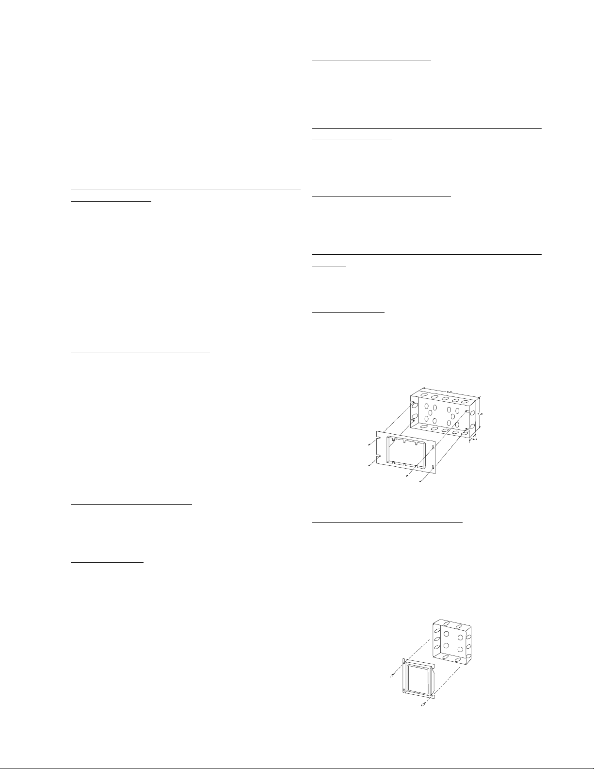
Install the back box TekTone® #IH353, (Steel City #H3BD or
exact equivalent) with TekTone® #IH352 (Steel City #3GC
plaster ring or exact equivalent), as shown in Figure 1 for
each station in system. Minimum dimensions of the back box
to be not less than 8.6" x 4.5" x 2.5". Minimum clearance from
live parts on the station to dead metal parts to be not less
than 1/2".
FIG. 1: IH352 Ring and IH353 Housing Installation
LI Series Corridor Dome/Zone Lights
Install the two gang back box (Steel City #H2BD or exact
equivalent) with the two gang plaster ring (Steel City #2GC
or exact equivalent), as shown in Figure 2 for each station in
system. Minimum dimensions of back box to be not less than
2-3/4" x 2-3/4". Minimum clearance from live parts on the
station to dead metal parts to be not less than
1/2". Minimum clearance from live parts on the station to
dead metal parts to be not less than 1/2".
LI Series Corridor Dome/Zone Lights
Run up to 7 conductor #18 stranded per light according to
type and location.
Copyright © TekTone Sound & Signal Mfg., Inc. All Rights Reserved.
FIG. 2: IH357 Ring and IH358 Housing Installation
IL600 NC205 Tek-DIGICARE® Manual • 7
Page 18

SF Series Peripheral Stations
Install the back box TekTone® #IH358 (Steel City #52171 or
exact equivalent) with TekTone® #IH357 (Steel City #52C14
plaster ring or exact equivalent), as shown in Figure 2, for
each station in system. Minimum clearance from live parts on
the station to dead metal parts to be not less than 1/2". To
insure a seal between the SF337C faceplate and wall, the
gasket must be mounted between the faceplate and wall. The
mounting screws with “O” Rings must be used to further
insure that there is a water-tight installation. Take care that
housing location will be such that the finished wall provides
a flat, even surface (installation of the housing in the seams
of tile will require additional caulking between gasket and
wall).
NOTE: Field wiring terminations should not be made
within NC260B, NC262A enclosures. TekTone®
recommends externally located connections (e.g.
mounted terminal/barrier strips, etc.) used in
conjunction with system cable assembles to terminate
field wiring.
NC260B Central Equipment
Ground the central equipment chassis to a good earth ground.
120 VAC must be provided to the central equipment. Do not
apply power until all connections to equipment have been
checked. If necessary, call the factory for other power
options. (Refer to NL205-E.)
2.5 WIRE CHECK-OUT
A. Use an ohm meter or other continuity checking device
to test for shorts or grounds. If shorts or grounds are
encountered, find and correct the problem before
continuing. All shield drain wires must show
continuity throughout the cable run.
B. Drains must be kept separate from all other
conductors and cannot be touching any part of
metal conduits or boxes. Drains should be taped
back at the end of cable runs. All drains should
return back to the central equipment (NC260B)
and connect to a good earth ground. NOTE:
Audio shields should be connected to a
dedicated earth ground with the system common
at one point. These shields should be continuous
until the end of the run, where they will be taped
back and isolated. Any unused wires in the
common control cables or in the selective line
cables should be grounded at the central
equipment with their other ends left floating. If
selective line cable has a shield, the shield
should be grounded at the central equipment
as well.
C. Make sure the minimum number of conductors needed
for all of the equipment being used in the system are
available. Make sure the maximum wiring distances
are not exceeded (see NL205-H).
NC262A Central Equipment Expander
NC262A Central Equipment Expander use 25 pin (DB25) and
2-pin headers to interconnect. 120 VAC must be provided to
the NC262A expander. (Refer to NL205-F.)
PK261A Dome Light Power Supply
Ground the dome light power supply chassis ground lug to
the chassis ground lug of the NC260B. 120 VAC must be
provided to the dome light power supply. DO NOT apply
power until all connections to equipment have been checked.
If necessary, call the factory for other power options. (Refer
to NL205-R.)
NC250/NC230 Master Stations
The master station(s) cable assembly should be plugged into
the wall plate supplied with each master station. Run cable
from the wall plate to the appropriate cable assembly at the
central equipment. (See Figure 3 and NL205-G for details.)
NC255 Master Station Expander
Plug cable provided into appropriate jack located in back of the
NC250 or NC230 Master Stations. (Refer to NL205-G.)
IR Series Stations
Each station is provided with cable assemblies terminated by
plug-in type connectors. Connect field wiring according to
wiring diagrams.
(CAUTION: Static electricity can cause damage to the
stations.)
2.6 WIRE CONNECTION
Make wire connections in accordance with the following
information and WIRING DIAGRAMS NL205-A thru
NL205-S. All stations and central equipment are supplied
with cable assemblies terminated by plug-in type connectors
for easy wiring.
8 • IL600 NC205 Tek-DIGICARE® Manual
LI Series Corridor Dome/Zone Lights
Connect wires as shown in wiring diagrams.
SF Series Peripheral Stations
Plug in connector/cable assembly supplied with each station.
Connect wires as shown in wiring diagrams.
Copyright © TekTone Sound & Signal Mfg., Inc. All Rights Reserved.
Page 19
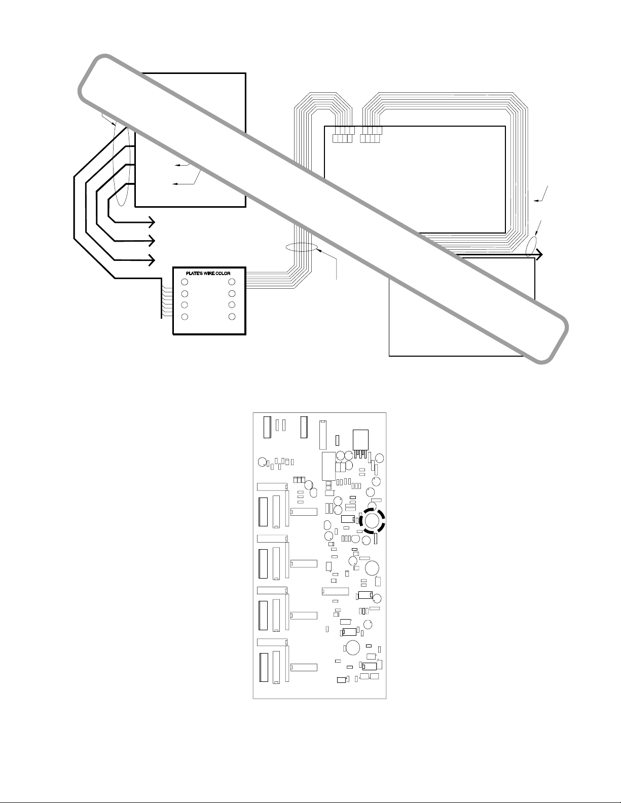
4-#18 shielded and 4-
#18 per master station.
(See note below)
NC260B Central Equipment
+18VDC
POWER ON
DIGITAL AUDIO IN
FAULT
CONTROL IN
CONTROL OUT
SYSTEM GROUND
DIGITAL AUDIO OUT
12345678
MASTER #1
MASTER #2
MASTER #3
MASTER #4
To Master #4
To Master #3
To Master #2
To Master #1
8 wires each
WHITE
8
BROWN
7
6
YELLOW
GREEN RED
BLUE
ORANGE
BLACK
Observe wire and pin NAMES when connecting equipment !!!
54321
7
6
8
Master IN Expander OUT
1=+18VDC
2=CONTROL IN
3=POWER ON
Refer to NL205-G
*ALL FIELD WIRING MUST BE TERMINATED
OUSIDE OF SYSTEM EQUIPMENT ENCLOSURES*
1
2
3
45
8 conductor Modular cable (7' cable
provided each Master Station) with
each Master Station
4=CONTROL OUT
5=DIGITAL AUDIO IN
6=FAULT
7=DIGITAL AUDIO OUT
8=SYSTEM GROUND
1
543
876
2
Modular jacks
NC250/230
MASTER STATION
2
1
Expander IN Expander OUT
678
54321
7
6
345
8
Modular jacks
NOTE:
Addressing NC255 Master Expanders incorrectly
will result in damage to units upon power application.
Check Figure 9 for correct dipswitch settings.
8 conductor
Modular cable
(1.3' cable provided
with each Master
Expander)
To other
Expanders
Wall Plate (TekTone® Part #PL467)
FIG. 3: Master Station Cable Assembly Wiring
!
NC255
MASTER EXPANDER
Audio
Volume
Control
FIG. 4: PM261A Selector Card
Copyright © TekTone Sound & Signal Mfg., Inc. All Rights Reserved.
IL600 NC205 Tek-DIGICARE® Manual • 9
Page 20
Call
Tone
Volume
Handset
Sensitivity
!
"
"
"
Master
Receive
Volume
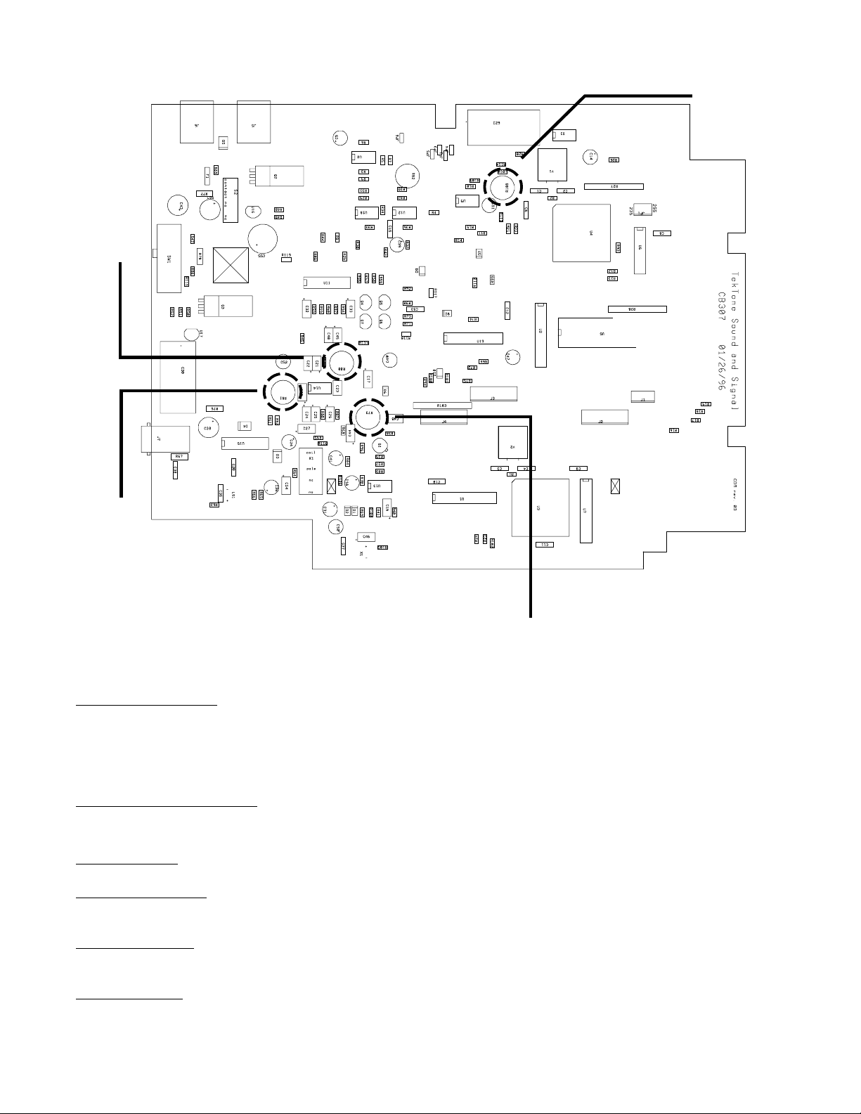
FIG. 5: Master Station Controls
2.7 VOLUME SETTINGS & ADJUSTMENTS
PM261A Selector Cards
The audio volume control is located on the selector card
(PM261A) as shown in Figure 4. Turn control counterclockwise to increase outgoing volume to patient stations.
(The PM261A is located within the NC260B/NC262A.)
NC250/NC230 Master Stations
All controls are preset at factory. The following lists the
volume controls found in Figure 5.
Call Tone Volume: Controls volume of incoming call tones.
Master Receive Volume: Controls talk volume from stations to
master.
Master
Talk
Volume
NOTE: Opening the master station requires a Scrulox® size
0 screwdriver (available from TekTone®, part number
HT004).
Master Talk Volume: Controls talk volume from master to
stations.
Handset Sensitivity: Controls handset voice circuit sensitivity
(VOX).
10 • IL600 NC205 Tek-DIGICARE® Manual
Copyright © TekTone Sound & Signal Mfg., Inc. All Rights Reserved.
Page 21
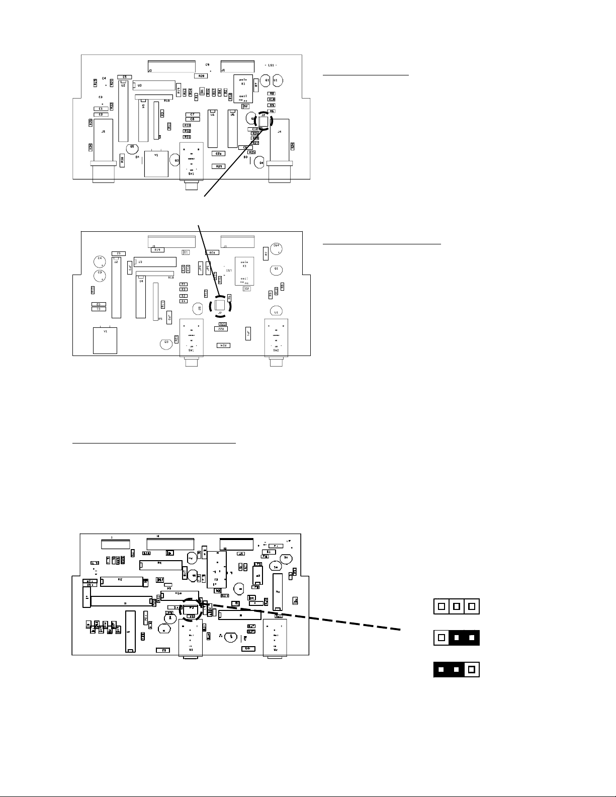
Code Fault Jumper on IR254-IR259 will be in one
of the 2 indicated positions.
IR260A Duty Station
The duty station call tone volume is adjustable via the 3- pin
header located as shown in Figure 7.
To assign zones for remote call annunciation, move the DIP
switch that corresponds with the desired zone number to the
“up” or “on” position. Any, all, or none of these switches may
be set in this manner. Move the switch “down” or “off” to
disable responses for that zone. The DIP switch is located on
the circuit board of the IR260A and must be set before
installation is complete and the power has been applied. (The
IR260A will not respond to the DIP switch settings until it has
been reset by powering it “off” and then back “on”.)
LI388A Corridor Zone Light
Remote call annunciation zones are assigned in the same
manner as the IR260A.
2.8 CONNECTIONS CHECK-OUT
Re-check all connections to equipment. If all wires and
connections are satisfactory, plug in central equipment to
dedicated outlet. Follow NC205 installation and power up
guidelines (Section 2.9), perform “System Test” (Section 7.0)
then configure system as desired (Section 5.0).
FIG. 6: Code Fault Jumper
IR254-IR259 Enhanced Patient Stations
To enable code fault reporting, remove the 2-pin jumper, see
Figure 6, from the station(s) circuit board header (excludes
IR250-253 and IR260A).
FIG. 7: IR260A Duty Station
2.9 NC205 Installation and Power Up Guidelines
Note: NC205 equipment should not be powered up until
these guidelines have been followed!
The equipment that comprises the NC205 System is ESD sensitive and ESD precautions must be taken when handling.
The use of properly rated ESD ground straps during installation is imperative. The NC205 System equipment is shipped
in ESD protective materials that should be retained for handling during equipment installation.
VOLUME CONTROL
LOW
MEDIUM
HIGH
Copyright © TekTone Sound & Signal Mfg., Inc. All Rights Reserved.
IL600 NC205 Tek-DIGICARE® Manual • 11
Page 22

When your equipment is received:
The ground clip of a ground strap should be connected to
the chassis ground lug in NC260B unit prior to working with
NC205 equipment.
Step 1:
Locate the following devices:
• Master station(s) (NC230 or NC250) and associated
CA037/7
• Master station wall plate(s) (PL467) and connector
harness(es) (CT308/24)
• Master station expander(s) (if used) (NC255) and
associated CA037
• Central equipment (NC260B) and associated ground
interconnect cable
• Central equipment expander (if used) NC262A, associated CT261, and associated ground interconnect cable
• Selector card(s) (PM261A)
• Common wire harness and selective wire harness
from PM261A selector card (CT306/24 and CT308/
24)
• Remote (patient, staff, or duty) station (IR250 - IR258
or IR260A)
• AC power cords (CA038), one for NC260B and (if
used) one for NC262A
• Remote stations common wire harness and (CT307)
Step 2:
If selector cards are already installed, skip to step 3. It is
important that selector card #1 be installed before power is
supplied to the system. Install the selector cards onto 15 pin
connectors near the top edge of PM260B Motherboard in the
NC260B Central Equipment as indicated in NL205-E. It is very
important to ensure that all pins are inserted properly. Improper pin insertion or pins not inserted will cause damage to
PM260B or PM261A modules. If an NC262A Central Equipment Expander is used, insert associated PM261A modules
also, referencing NL205-F.
NOTE: The NC260B Central Equipment includes a removable “sled” that allows for the removal of the PM260B
Motherboard and associated PM261A selector cards (reference label inside of NC260B for removal instructions).
The sled should be removed during IH260 housing installation process to prevent damage to electrical equipment
or PM261A selector card replacement for ease of card installation.
Step 4:
Plug the 8 pin connector of a master wiring harness to master
connector number 1 as indicated in NL205-E and NL205-G.
Step 5:
Insert one end of CA037/7 cable (included with master station ) into the PL467 plate of the master wiring harness.
Step 6:
Select a master station and insert the other end of CA037/7
cable into the master station receptacle referred to as “Master IN” in NL205-G .
Step 7:
The master station used should be set to address number 1.
This is accomplished by setting all four dipswitches (accessible via an opening in back of master cabinet) to the “OFF”
or “UP” position as indicated in figure 9.
Step 8:
Locate the CT306/24, CT308/24, and CT307 connectors. Connect them together as shown in NL205-E, NL205-I, NL205-J,
NL205-K, NL205-L, NL205-M, NL205-N depending on the
type of station used for test. This station connector harness
will serve to connect the remote station to the NC260B for
this procedure.
Step 9:
Plug the 6 pin connector of station connector harness on to
either 6 pin common connector of the PM261A Selector Card,
within NC260B, as referenced in NL205-E.
Step 10:
Plug 8 pin connector of station connector harness on to bottom most 8 pin selector connector of the PM261A Selector
Card as referenced in NL205-E.
Step 11:
Plug 7 pin connector of station connector harness on to the
7 pin connector of test remote station. Reference NL205-I,
NL205-K, NL205-L, NL205-M, or NL205-N depending on the
type of station used for test.
Step 12:
Set dipswitch number 1 on the PM260B Motherboard to the
“ON” position as referenced in section 5.4-1, Central Equipment Reset Procedure. This dipswitch setting will cause the
“flash-ram” in the NC260B to be cleared on power up.
Step 3:
Locate the associated PL467 and CT308/24 for each master
station. The CT308/24 should be connected to the PL467 as
shown in NL205-G of the IL600 manual, creating a master
wiring harness. A harness should be made for each master
station.
12 • IL600 NC205 Tek-DIGICARE® Manual
Step 13:
NOTE: Only qualified technical personnel should make
110 VAC connections! Do not connect CA038 to 110 VAC
outlet until 110 VAC terminal block connections are made
and the safety cover is reinstalled onto the terminal block.
Remove the end of the CA038 cable that does not have the
110 VAC connector on it. Strip back the cable so that the 3
conductors are exposed and insert them into the 110 VAC
Copyright © TekTone Sound & Signal Mfg., Inc. All Rights Reserved.
Page 23

terminal strip in the NC260B housing as referenced in NL205-Q.
as per figure 10. The master expander’s case will need to be
opened to allow access to the dipswitch. Set switch 1 to the
Step 14:
Insert other end of CA038 cable into 110VAC outlet.
“ON” or “UP” position, leaving switches 2 and 3 in the “OFF”
or “DOWN” position. Switch 4 will be factory set as per
Figure 10.
Wait until the LEDs on the PM261A Selector Cards begin to
flash. NOTE: Flashing pattern is irregular and is not an indication of a FAULT condition. Return dipswitch number 1 on
the PM260B Motherboard to its original “OFF” position. If
PM261A LED(s) do not flash, re-check master station wiring.
Step 18:
Insert one end of the master expander’s CA037 interconnect
cable into the master station receptacle referred to as “Ex-
pander OUT” in NL205-G.
At this time the NC205 set up should be operating properly
with no “FAULT” LEDs lit on the bottom edge of the PM260B
Motherboard.
Step 15:
The master station’s “flash-ram” must now be cleared. To
accomplish this, set dipswitch number 4 to the “ON” or
“DOWN” position. Now set dipswitch number 1 to the “ON”
or “DOWN” position and then return it to the “OFF” or “UP”
position. Wait, before proceeding, to verify that the master
stations’s “TALK” LED illuminates for a brief period of time
(NOTE: This should occur within 10 to 15 seconds.) If this
does not occur, perform step 15 again. Return dipswitch 4 to
the “OFF” or “UP” position.
At this time, no “FAULT” conditions should be annunciat-
ing from the master or central equipment. If any “FAULT”
LEDs are lit, note the “FAULT” as shown in section 5.6-2,
Faults (for central equipment) or in section 3.3, Master Station and Expander Displays (for master station). Once the
“FAULT” condition has been noted, remove power from the
system.
If no “FAULTS” have occurred, place a call from the remote
station by depressing the call button on the station or associated call cord. This call should be annunciated at the master station by a beeping tone and a flashing yellow LED.
Press the selector button associated with the LED and the
master station will open an audio path to the station. This will
be indicated by the red “IN-USE” LED lighting on the remote
station. There will be some acoustic feedback due to the
close proximity of the master and station.
As the procedure is followed, the operation of the system
should be observed for the introduction of functional problems and audio noise each time equipment is added. If a problem becomes apparent, the last system addition should be
suspect.
Step 19:
Insert the other end of the CA037 interconnect cable into the
master expander receptacle referred to as “Expander IN” in
NL205-G.
Step 20:
Repeat steps 12 - 15 to power up system.
Step 21:
Repeat steps 16 - 20 until all master expanders for the master
station are connected. NOTE: Each master station expander
must have a unique address as per figure 10. Connection of
incorrectly addressed master expanders will result in dam-
aged equipment. Additional expanders will connect to the
“Expander OUT” receptacle of the previous master expander.
Reference NL205-G.
Step 22:
Repeat steps 4 - 21 until all master stations and master ex-
panders are connected. NOTE: Each master station should
have a unique address indicated by figure 9. Each master
station’s address should correspond to the connector it is
plugged into on the PM260B motherboard as indicated by
NL205-E and NL205-G. (I.e., master number 2 should be
plugged onto master connector number 2 and so on, respec-
tively.)
Step 23:
If a central equipment expander is used, locate and address
all three sets of dipswitches within the NC262A Central Equip-
ment Expander to number 1 by sliding dipswitch 1 to the
“ON” or “UP” position. Dipswitches 2, 3, and 4, should be
set to the “OFF” or “DOWN” position.
Step 24:
Connect the NC262A to the NC260B unit by inserting the
male end of the CT261 into the female DB25 receptacle within
the NC260B chassis. Reference NL205-E and NL205-F.
Step 16:
Power down system by removing the CA038 from the 110
VAC outlet.
Step 17:
If master station expanders are used on the system, select
one unit and set its address to be master expander number 1
Copyright © TekTone Sound & Signal Mfg., Inc. All Rights Reserved.
Step 25:
Take the ground interconnect cable from the NC260B Central
Equipment and connect to the NC260B chassis ground lug.
Take the ground interconnect cable from the NC262A and
connect to the NC262A chassis ground lug. Connect the
NC262A chassis ground lug to the NC260B chassis ground
lug (wire nuts or electrical tape is suggested for insulation of
IL600 NC205 Tek-DIGICARE® Manual • 13
Page 24

connections). Reference NL205-E and NL205-F for locations
to insert ground interconnect cables within the NC260B and
NC262A chassis. NOTE: The NC262A unit requires a 110
VAC connection source for power (reference step 13 for connection). NOTE: Only qualified technical personnel should
make 110 VAC connections! Do not connect CA038 to 110
VAC outlet until 110 VAC terminal block connections are
made and the safety cover is reinstalled on to the terminal
block.
The audio quality should be observed and if noise is present
the shields for the master cable wiring (which should be connected to the NC260B chassis ground lug as indicated by
NL205-E) should be checked for proper connection and undesired grounds. The earth ground connection to the NC260B
chassis should also be checked.
Once the master station and master station expanders are
operating properly, proceed to step 3.
Step 26:
Follow steps 12 - 15 to power up system and test the NC262A
unit.
Personnel planning to install this equipment should take this
opportunity to familiarize themselves with basic system operations. See section 4.0, Operational Procedures, for operational instructions of the NC205 system.
When your equipment is installed:
The above listed procedure should be followed at the jobsite
and operation of the NC205 equipment should not change.
Usually, this setup will be performed in an electrical or other
dedicated room once the NC260B and NC262A housings have
been mounted.
NOTE: The CA038 is not intended for field installation
and should be removed prior to site installation!
Once the installation personnel have achieved the operational state described in the above steps 1- 30, connection of
field devices may commence, following the procedure listed
below.
Step 1:
Ensure that NC205 system is powered down and that dipswitch
number 1 on the PM260B motherboard is in the “ON” position to allow new equipment to be recognized. After each
power up the installation personnel should wait for the
PM261A Selector Card(s) LED(s) to begin flashing and then
dipswitch number 1 should be returned to the “OFF” position. Observe the PM260B Motherboard for “FAULT” indi-
cations.
Step 3:
Repeat steps 1 and 2 for each master station, until all masters
and master station expanders are operational. The operation
of the system should be observed each time for the introduction of functional problems and audio noise. If a problem
becomes apparent, the last system addition should be suspect.
Step 4:
Ensure that the NC205 system is powered down and that
dipswitch number 1 on the PM260B Motherboard is in the
“ON”position.
Step 5:
The wiring to the first remote station common wire cable run
should be verified and checked for shorts and grounds. Reference NL205-I, NL205-J, NL205-K, NL205-L, NL205-M,
NL205-N, NL205-O and NL205-P. Connect the common wires
of the first station run to the PM261A Selector Card common
connector as indicated by NL205-E.
Step 6:
The wiring to the first remote station selective wire cable run
should be verified, checked for shorts and grounds. Connect
the selective wires of the first station run to the PM261A
Selector Card selective connector(s) as indicated by NL205E.
Step 7:
The local peripheral wiring for each remote station connected
to the first cable run should be verified and checked for shorts
and grounds. Reference NL205-I, NL205-J, NL205-L, NL205M, NL205-N, NL205-O and NL205-P.
Step 2:
The wiring to the first master station should be verified and
checked for shorts and grounds from the central equipment
location to first master station location. Once done, the first
master station, and associated master station expanders, may
be connected at its field location. The system should be powered up and checked for fault conditions. If fault conditions
occur, they should be noted and then the system should be
powered down. The wiring should be re-checked for problems. If problems are located, correct and proceed with step 2
again.
14 • IL600 NC205 Tek-DIGICARE® Manual
Step 8:
Power up the NC205 system and wait for the LED(s) on the
PM261A Selector Card(s) to begin flashing. Return dipswitch
1 on the PM260B Motherboard to the “OFF” position. Observe the PM260B Motherboard for “FAULT” indications.
Step 9:
A call should be placed and answered by a master station
from each remote station connected to the first run. The system should be observed so that operational anomalies may
be identified. During observation, each peripheral device connected to the remote station(s) should be activated.
Copyright © TekTone Sound & Signal Mfg., Inc. All Rights Reserved.
Page 25

Step 10:
Repeat steps 4 - 9 for each remote station cable run, until all
remote stations are operational. The operation of the system
should be observed each time for the introduction of functional problems and audio noise. If a problem becomes apparent, the last system addition should be suspect.
Common Mistakes
Compiled below is a brief list of items to pay extra attention to
during this procedure and all other facets of the NC205 installation.
• Incorrectly addressing NC250/NC230 Master Stations
or NC255 Master Station Expander
• Plugging the cable from the PL467 Wall Plate into the
wrong socket on the back of the NC250/NC230
Master, or plugging the cable from a NC255 Master
Expander into the wrong socket on the back of the
NC250/NC230 Master.
• Folded or missing insulator label on back of
PM261ASelector Card
• Powering up PK261A Dome Lamp Power Supply
without first powering up NC260B Central Equipment
• Powering up NC260B Central Equipment without
powering up NC262A Central Equipment Expander
• Ensure that any spare selector lines are grounded in
addition to selective ground lines
NOTE: Damage to NC205 equipment can occur from the
above items!
Copyright © TekTone Sound & Signal Mfg., Inc. All Rights Reserved.
IL600 NC205 Tek-DIGICARE® Manual • 15
Page 26

16 • IL600 NC205 Tek-DIGICARE® Manual
Copyright © TekTone Sound & Signal Mfg., Inc. All Rights Reserved.
Page 27
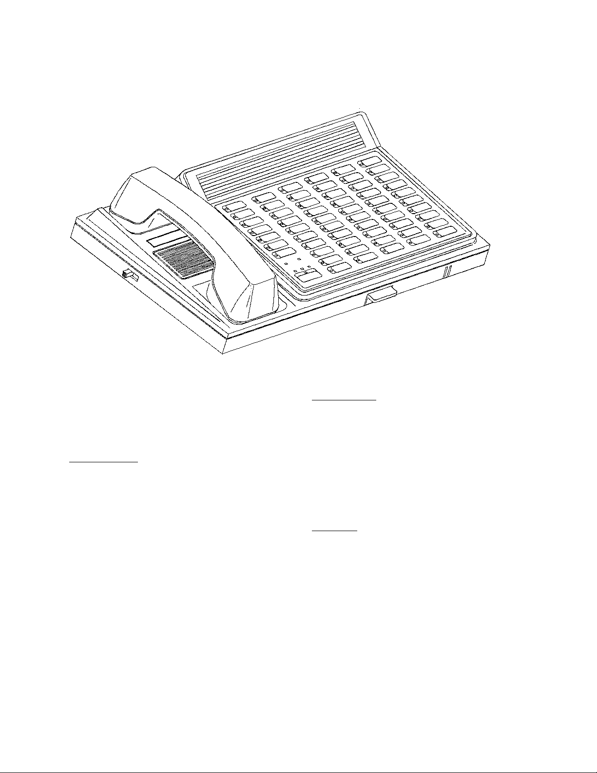
3.0 SYSTEM EQUIPMENT DESCRIPTIONS
The following section provides complete operating information for all NC205 System Equipment in addition to drawing
references for use in locating and describing all controls and indicators. System operators should read the following instructions
concerning system equipment and terms used in conjunction with the equipment.
Y
C
A
V
I
R
P
W
O
L
L
O
F
Y
T
I
R
O
I
R
P
F
F
A
T
S
E
N
O
Z
E
G
A
P
RESET
FAULT
ON
ER
W
PO
ITY
PRIOR
K
L
A
T
INDEX
TekTone
®
3.1 NC250/NC230 MASTER STATION
Refer to Figure 8 for locations and names of controls and
indicators. A brief description of the operating controls for the
NC250/230 follows.
Function Buttons
These buttons select system functions as described below.
PRIVACY (red) : Toggles a station’s privacy; also displays stations
in privacy mode (enhanced PC’s only).
FOLLOW (orange): Initiates staff and/or room follower operations.
LED will light while master is in follower mode.
PRIORITY (yellow): Upgrades a stations call priority level; also
displays stations at “PERSONAL ATTENTION” (enhanced PC’ s only) and
“EMERGENCY” priority levels.
STAFF (green) : Enters or cancels a staff service request; also
used to view stations where staff presence is
registered or needed.
ZONE (blue) : Displays zone assignments and status
information for masters and stations; also used
for zone paging functions and to display faulty
stations.
PAGE (violet) : Used for zone, all call, and staff paging.
RESET (black) : Ter minates most operations; also indicates
that the system is processing information by
flickering its LED (USER MUST WAIT).
TALK (dark gray) : Talk/Listen button for audio communications
between stations and masters. Talk LED solid
indicates that audio path has been established;
flashing indicates station busy.
FIG. 8: NC250 Master
Numerical Keys
These are dual function buttons. Under normal operation they
are station selector buttons. They are also used to assign and
reassign specific zones to stations and masters, and for
master-to-master selections (see Section 5.0).
“0 ” : Clears all zone assignments from stations or
masters.
“1 ” - “8 ” : Deletes or adds zones 1-8 to masters and stations;
also indicates current zone assignments for
stations and/or masters.
“9 ” : Adds all zones to masters or stations.
Alpha Keys
These are dual function buttons. Under normal operation they
are station selector buttons. They are also used to program
and display the status of stations or masters.
“B” = PRIVACY : When lit, indicates a pre-selected station is in
privacy.
“C” = PAGE INHIBIT: When lit, indicates a pre-selected station is
blocked from receiving “PAGE”; can be
toggled ON/OFF.
“D” = PRIORITY : Displays stations whose priority has been
upgraded (standard stations only).
“E” = BATH : Marks a peripheral device as an
“EMERGENCY/BATH” stand alone station
(when unmarked, a stand alone registers
“HIGH” priority).
“F” = FAULT : Used to disable fault inspection for a pre-
selected station (must be marked for IR250/
IR251/IR252/IR253/IR260A and stand alone
stations).
Copyright © TekTone Sound & Signal Mfg., Inc. All Rights Reserved.
IL600 NC205 Tek-DIGICARE® Manual • 17
Page 28
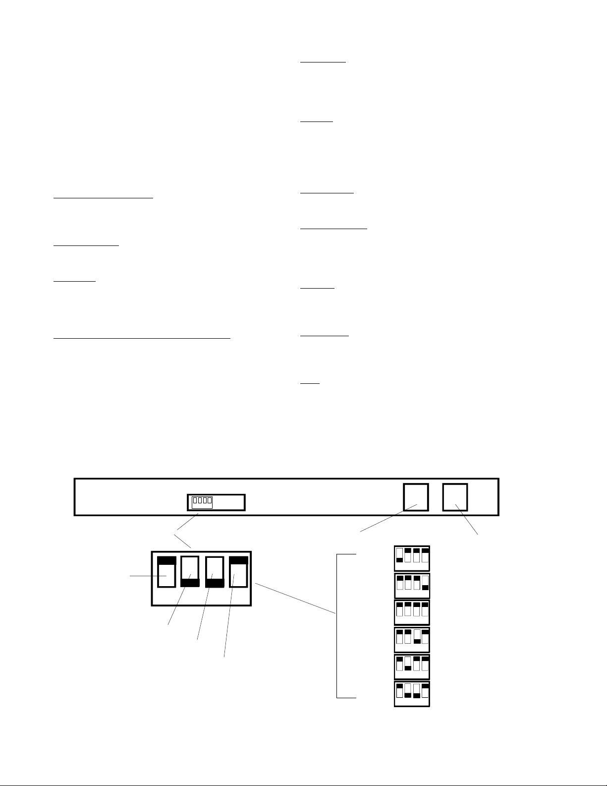
“G” = FIRE : Used to toggle stations from announcing
“CODE” to announcing “FIRE” calls. When
lit, indicates any station that has been set to
annunciate “FIRE” type calls (smoke detector
connections).
“H” = STAFF : Used to mark stations for master-to-staff
communications.
“I” = MASTER : Used to mark buttons for master-to-master
communications.
“I” = BEEP TONE : Toggles beep tones (when a button is pressed)
at the master.
“J” = ANNOUNCE : Toggles pre-announce tones (beep when a
call is placed) at the master.
DIP Switch
The master control DIP switch is located on the rear of the
NC250/NC230 Master Stations. Refer to Figure 9 for location and function of control switches.
Handset
The handset is used to provide confidential conversation
when loudspeaker communication is not desired, or to
permit conversation when high ambient noise is present. To
use, simply pick up handset.
Station Selector Buttons
Used to select stations for initiating calls, responding to calls,
and programming.
Power ON LED
Indicates AC power to the system.
Fault LED
The fault LED is steadily illuminated when failure of a station
or the master station is detected. The fault LED flashes when
a central equipment fault is detected.
Priority LED’S - GREEN, AMBER, and RED
The master will display the highest priority of all incoming
calls. For low priority calls, the GREEN LED will light and be
accompanied by a call tone once every eight seconds. For
medium priority calls, the AMBER LED will light and be
accompanied by a slow repeating tone. For high priority calls
the RED LED will light and be accompanied by a fast repeating
tone. (Code is indicated by steady RED priority LED, fire is
indicated by flashing RED priority LED).
REAR VIEW OF MASTER
Hook Switch
The hook switch activates or terminates handset operation.
Volume Control
The volume control permits adjustment of the incoming
voice communication. Slide switch towards front of unit to
increase volume; towards back to decrease (3 positions).
Speaker
The speaker is used to listen to remote stations or other
masters and to annunciate call tones.
Microphone
The microphone is used to talk to remote stations or other
masters.
Tray
The tray holds the Quick-Reference Guide to system
operations.
1 2 3 4
MASTER CONTROL DIP SWITCH
RESET
SWITCH
1 2 3 4
ADDRESS
SWITCH
(most significant
bit)
ADDRESS
SWITCH
(least significant
bit)
18 • IL600 NC205 Tek-DIGICARE® Manual
PROGRAMMING
SWITCH
FIG. 9: NC250/230 Master DIP Switch Controls
KEY PAD EXPANSION PORT
(to NC255 Expander)
Copyright © TekTone Sound & Signal Mfg., Inc. All Rights Reserved.
ON #
1 2 3 4
1 2 3 4
1 2 3 4
1 2 3 4
1 2 3 4
1 2 3 4
(from NC260B Central Equipment)
RESET
PROGRAMMING
MODE ON
MASTER #1
ADDRESS
MASTER #2
ADDRESS
MASTER #3
ADDRESS
MASTER #4
ADDRESS
MASTER CONTROL PORT
Page 29
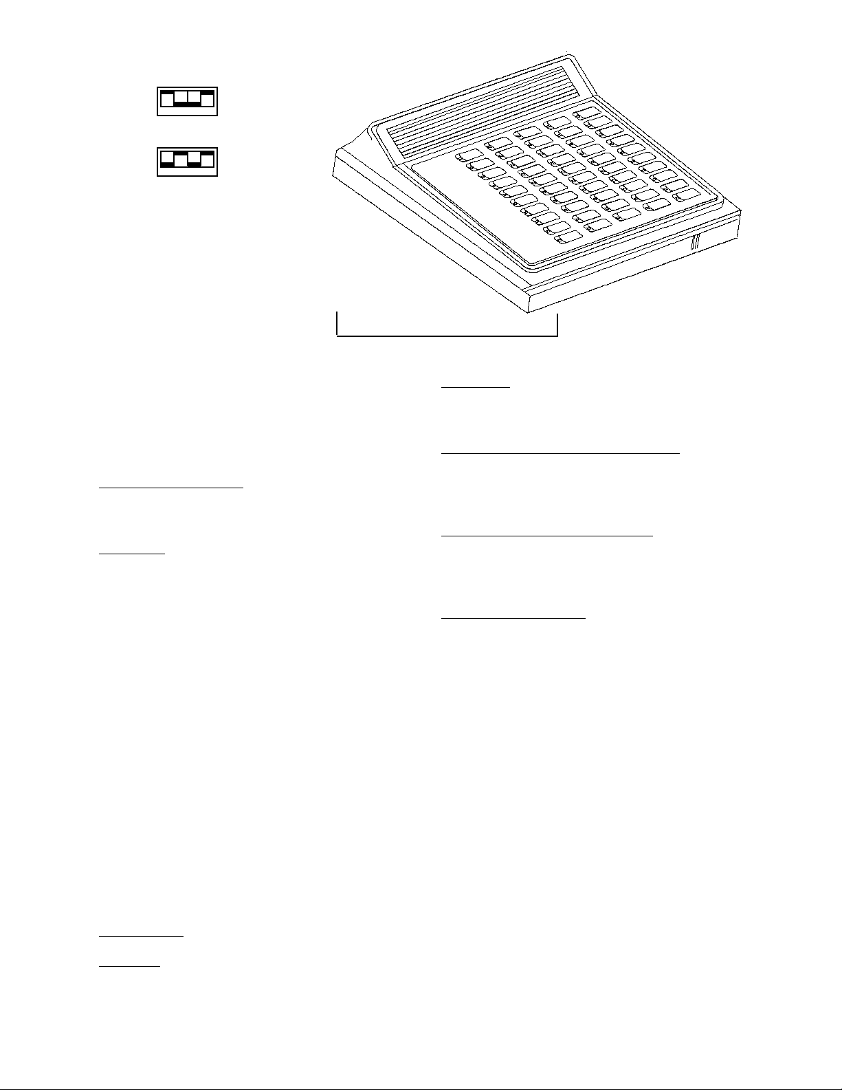
ON$
Expander #1
ON$
Expander #2
1 2 3 4
1 2 3 4
NOTE: Switch settings as shown are
for NC255-50 station expanders.
$
FIG. 10: NC255 Master Expander
3.2 NC255 MASTER EXPANDER
Refer to Figure 10 for NC255 Master Expander DIP switch
settings. A brief description of the operating controls for the
NC255 follows.
Station Selector Buttons
Used to select stations for initiating calls, responding to calls,
and programming. The NC255 has 50 buttons.
DIP Switch
The DIP Switch is located within the NC255 Master Expander.
Positions “1” and “2” select the address of expander. Refer to
Figure 10.
3.3 MASTER STATION & EXPANDER
DISPLAYS
There are three basic levels of calls:
High Priority: FIRE* (supplementary only, see note)
CODE
Medium Priority: BATH/EMERGENCY
CORD OUT/PRIORITY
Low Priority: PERSONAL ATTENTION
ROUTINE
*NOTE: The NC205 is not tested as a fire alarm system and is
not intended as a primary indication means for
evacuation.
Call Location: Indicated by the station selector buttons.
Code Calls: Indicated by the rapid flashing of the specific
station’s selector button LED, steady illumination of the RED
priority LED, and a rapid pulsating call tone.
Emergency/Bath/Priority/Cord Out Calls: Are indicated by
the medium flashing of the specific station’s selector button
LED, steady illumination of the AMBER priority LED, and a
medium pulsating call tone.
Personal Attention & Routine Calls: Are indicated by the
slow flashing of the specific station’s selector button LED, the
steady illumination of the GREEN priority LED, and a slow
pulsating call tone (once every eight seconds).
System Fault Indications: System faults are cancelled only at
such time as the fault is corrected (see Section 5.6-2 for
complete list of faults). Faults will appear as listed below:
CODE FAULT: Indicated at the Master Station by a solid
illumination of the Fault LED. Pressing the Zone Button
twice will cause the affected station’s selector LED to flash
at a slow rate for eight (8) seconds. Refer to section 5.6-2 for
further information.
- Wires between a code station and a patient station are
defective.
- The code station is defective.
- The patient station is defective.
STATION FAULT: Indication at the Master Station the
same as described above. Refer to section 5.6-2 for further
information.
MASTER FAULT: Indication at the Master Station by a
solid illumination of the Fault LED. Refer to section 5.6-2 for
further information.
Fire Calls: Are indicated by the rapid flashing of the specific
station’s selector button LED, the rapid flashing of the RED
priority LED, and a rapid pulsating call tone.
Copyright © TekTone Sound & Signal Mfg., Inc. All Rights Reserved.
CENTRAL EQUIPMENT OR MASTER FAULT:
Indication by a rapid flashing of the Fault LED at the Master
Station. No indication at the Central Equipment.
IL600 NC205 Tek-DIGICARE® Manual • 19
Page 30
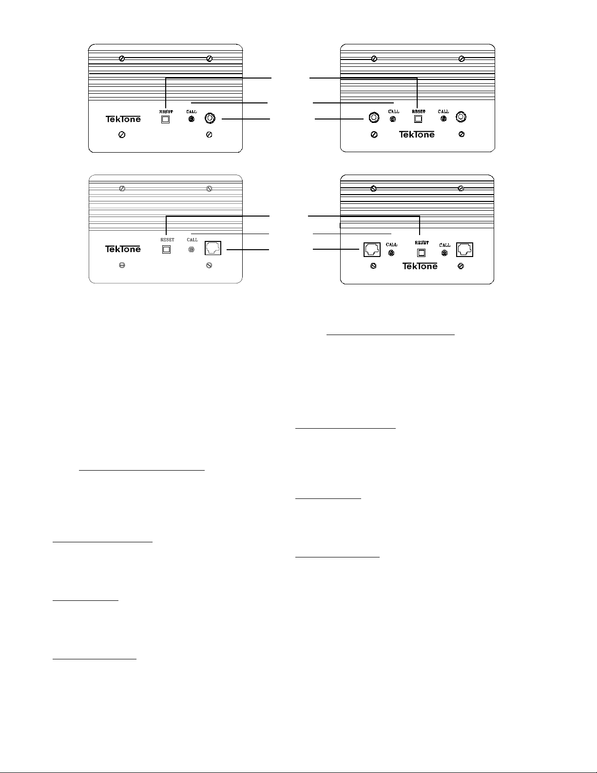
IN USE LED
# #
% "
CALL-PLACED
CALL CORD
RECEPTACLES
IR251/IR255 IR252/IR256
IN USE LED
#
#
% "
CALL-PLACED
CALL CORD
RECEPTACLES
IR257
FIG. 11: IR251/IR252 Standard and IR255/IR256/IR257/IR258 Enhanced Patient Stations
3.4 PATIENT STATIONS
TekTone® IR Series Stations use high quality speaker/
microphones for voice communications and tone signaling.
Due to the high sensitivity of the microphone, it is not
necessary for the patient to move close to the unit or to raise
the voice above a normal speaking level to be heard.
LED
LED
##
#
#
IR258
3.4-2 IR255-IR258 Enhanced Stations
These stations provide outputs for three or four lamp dome
lights, and additional inputs for presence stations, code
stations, and smoke detectors. These stations provide circuitry
for supervision of code station and associated wiring. Power
and select wires are supervised by central equipment.
Refer to Figure 11 for locations and names of controls and
indicators. A brief description of the operating controls for the
patient stations follows:
3.4-1 IR251/IR252 Standard Stations
These stations do not provide supervision circuitry, outputs
for three or four lamp dome lights, or inputs for presence and
code stations.
Reset Button/In-Use LED
The “RESET” button is used to cancel a call placed from the
station. The LED illuminates whenever communication to the
master station is engaged.
Call-Placed LED
The “CALL-PLACED” LED is steadily illuminated whenever
a call is placed from the station and flashes slowly during a cord
out condition.
Call Cord Receptacle
There are two kinds of call cord receptacles. The modular
(rectangular) type is for use with SF301P Pillow Speakers or
SF311/SF312 Call Cords. The 1/4" phone jack (round) type is
for use with SF301/SF302 Call Cords. Single bed stations have
one call cord receptacle; dual bed stations have two.
Reset Button/In-Use LED
The “RESET” button is used to cancel a call placed from the
station. The LED illuminates whenever communication to the
master station is engaged. The “RESET” button can also be
used to cancel a staff request at a station.
Call-Placed LED
The “CALL-PLACED” LED is steadily illuminated whenever
a call is placed from the station. The LED flashes when a call
cord is pulled from its socket.
Call Cord Receptacle
There are two kinds of call cord receptacles. The modular
(rectangular) type is for use with SF301P Pillow Speakers or
SF311/SF312 Call Cords. The 1/4" phone jack (round) type is
for use with SF301/SF302 Call Cords. Single bed stations have
one call cord receptacle; dual bed stations have two.
20 • IL600 NC205 Tek-DIGICARE® Manual
Copyright © TekTone Sound & Signal Mfg., Inc. All Rights Reserved.
Page 31
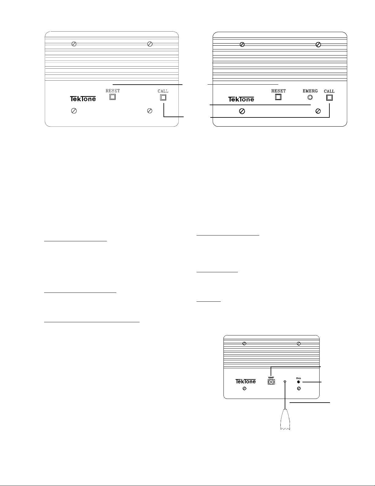
#
IN USE LED
#
$
CALL-PLACED
IR250/IR254 IR260A
FIG. 12: IR250 Standard/IR254 Enhanced Staff Stations and IR260A Duty Stations
3.5 IR250 STANDARD/IR254 ENHANCED
STAFF & IR260A DUTY STATIONS
The IR250 does not provide supervision circuitry, outputs for
three or four lamp dome lights, or inputs for presence and code
stations. These features are found on the IR254. Refer to
Figure 12 for locations and names of controls and indicators.
A brief description of the operating controls for the staff and
duty stations follows:
Reset Button/In-Use LED
The “RESET” button is used to cancel a call placed from the
station. The LED illuminates whenever communication to the
master station is engaged. (See special features below for
additional uses of the “RESET” button on the IR260A Duty
Station.)
Call Button/Call-Placed LED
The “CALL” button is used to place a call to the master. The
LED illuminates when a call is placed.
EMERGENCY
LED
LED
$
3.6 IR253 STANDARD PULL CORD
PATIENT STATION
The IR253 does not provide supervision circuitry, outputs for
three or four lamp dome lights, or inputs for presence and code
stations. Refer to Figure 13 for locations and names of
controls and indicators. A brief description of the operating
controls for the pull cord patient station follows:
Reset Button/In-Use LED
The “RESET” button is used to cancel a call placed from the
station. The LED illuminates whenever communication to the
master station is engaged.
Call-Placed LED
The “CALL-PLACED” LED is steadily illuminated whenever
a call is placed from the station.
Pull Cord
The IR253 is supplied with a 6' nylon pull cord and pendant.
$
IR260A Duty Station Special Features
The IR260A does not provide supervision circuitry or inputs for
presence and code stations. The “RESET” button may be used
to silence the tone signal for low priority calls. Medium and high
priority tone signals cannot be silenced. The tone will return only
after all low priority calls have been cancelled, or a medium or high
priority call is placed.
Low Priority Calls: A call tone is repeated once every 8
seconds.
Medium Priority Calls: The “EMERGENCY” LED will flash
and a slow, repeating tone is heard from the speaker.
High Priority Calls: The “EMERGENCY” LED will flash and
a fast repeating tone is heard from the speaker.
Fire: The “EMERGENCY” LED will flash at a fast rate and a fast
repeating tone will be heard from the speaker.
Copyright © TekTone Sound & Signal Mfg., Inc. All Rights Reserved.
RESET
BUTTON
CALL-PLACED
IR253
#
%
%
FIG. 13: IR253 Standard Pull Cord Patient Station
IL600 NC205 Tek-DIGICARE® Manual • 21
LED
PULL
CORD
Page 32
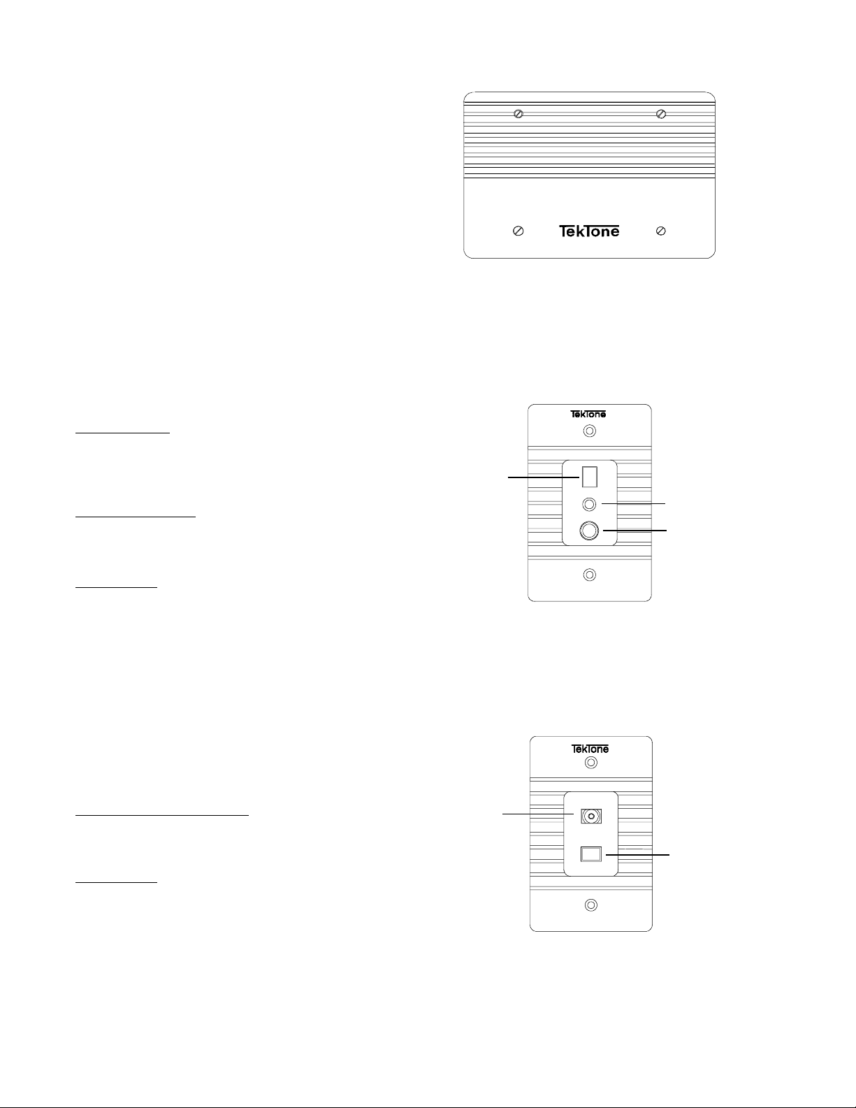
3.7 IR259 ENHANCED
MULTIPURPOSE STATION
Refer to Figure 14 for a display of the IR259. The IR259
circuitry is mounted on a blank faceplate and provides external
connections for a “CALL” button, a “RESET” button, and
peripheral devices. The device(s) used to emulate the “CALL”
and “RESET” buttons must use momentary contacts. Normally
open or double pole/double throw switches can be used.
(Refer to NL205-O for wiring instructions.)
3.8 SF100C VISUAL STATION
Refer to Figure 15 for location and names of controls and
indicators. The SF100C is intended to be used as a stand-alone
station. A brief description of the operating controls for the
SF100C follows:
Call-Placed LED
The “CALL-PLACED” LED is steadily illuminated whenever
a call is placed from the station or a call cord is pulled from its
socket.
Call Cord Receptacle
The 1/4" phone jack (round) is for use with SF301/SF302 Call
Cord.
IR259
FIG. 14: IR259 Enhanced Multipurpose Station
CANCEL
BUTTON
"
CANCEL
%
CALL PLACED
%
CALL-PLACED
LED
PHONE
CORD
RECEPTACLE
Cancel Button
The “CANCEL” button is used to cancel a call placed from the
station.
3.9 SF101C VISUAL STATION
Refer to Figure 16 for location and names of controls and
indicators. The SF101C is intended to be used as a stand-alone
station. A brief description of the operating controls for the
SF101C follows:
Call-Placed LED / Push button
The “CALL-PLACED” LED / Push button is steadily illuminated
whenever a call is placed from the station.
Cancel Button
The “CANCEL” button is used to cancel a call placed from the
station.
SF100C
FIG. 15: SF100C Visual Station
CALL-
PLACED
LED
CALL PLACED
"
CANCEL
SF101C
FIG. 16: SF101C Visual Station
%
CANCEL
BUTTON
22 • IL600 NC205 Tek-DIGICARE® Manual
Copyright © TekTone Sound & Signal Mfg., Inc. All Rights Reserved.
Page 33
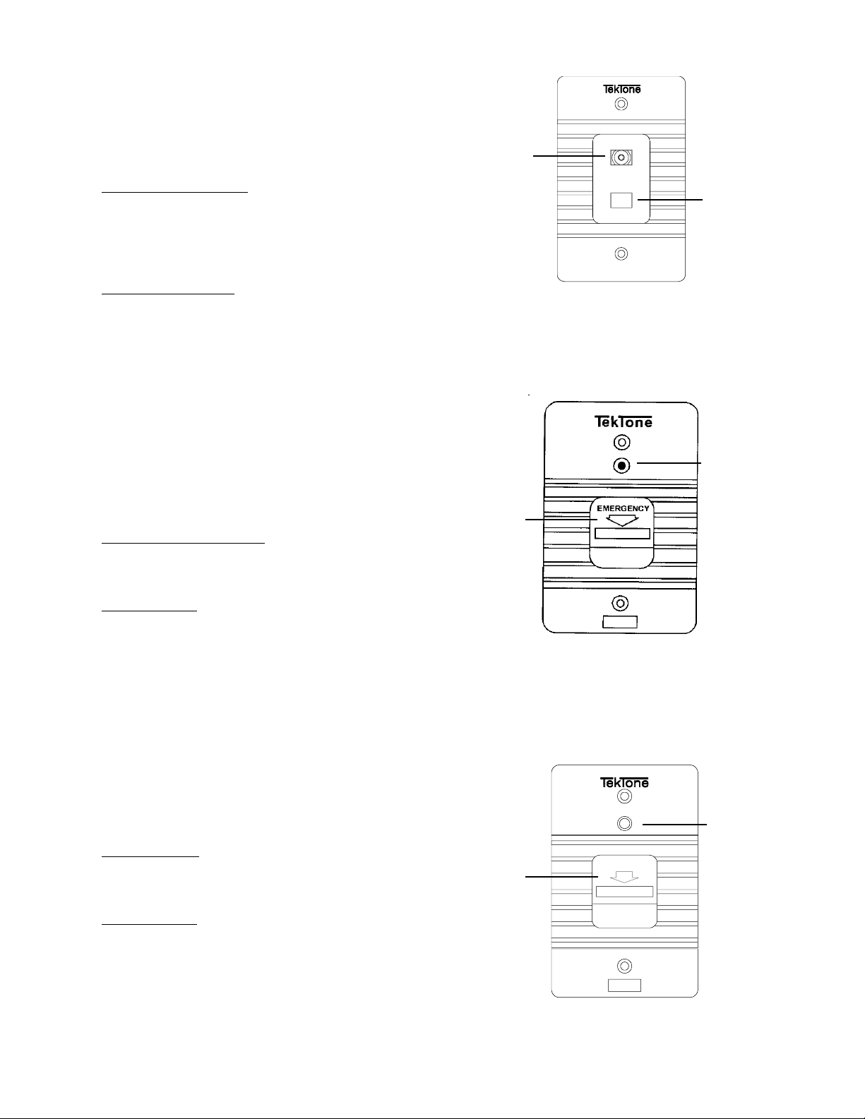
3.10 SF250 STAFF PRESENCE STATION
Refer to Figure 17 for location and names of controls and
indicators. A brief description of the operating controls for the
SF250 follows:
STAFF
LED
STAFF
"
Staff Registration Button
The “STAFF REGISTRATION” button is used to register staff
presence in a room and resets any routine, personal attention,
or priority calls made. The same button is used to cancel the
staff presence indication.
Staff Registration LED
The green LED flashes to indicate staff presence required and
lights steadily while the staff member is registered.
3.11 SF337C/SF340B PULL CORD SHOWER/
EMERGENCY STATION
Refer to Figure 18 for locations and names of controls and
indicators. A brief description of the operating controls for the
SF337C/340B follows:
Emergency Pull Down Lever
The “EMERGENCY” pull down lever is used to place and
cancel “EMERGENCY” and “BATH” calls.
%
SF250
FIG. 17: SF250 Staff Presence Station
%
EMERGENCY
LEVER
"
STAFF
REGISTRATION
BUTTON
CALL-PLACED
LED
Call-Placed LED
The red LED flashes to indicate call placement.
NOTE: Refer to NL205-P for stand alone operation wiring.
3.12 SF341B CODE CALL STATION
Refer to Figure 19 for locations and names of controls and
indicators. A brief description of the operating controls for the
SF341B follows:
Call/Reset Lever
The “CALL/RESET” lever is used to place and reset “CODE”
priority calls.
Call-Placed LED
The red LED flashes to indicate call placement.
SF337C/SF340B
FIG. 18: SF337C/SF340B Pull Cord
Shower/Emergency Station
CALL/RESET
LEVER
CODE
"
SF341B
FIG. 19: SF341B Code Call Station
%
CALL-PLACED
LED
Copyright © TekTone Sound & Signal Mfg., Inc. All Rights Reserved.
IL600 NC205 Tek-DIGICARE® Manual • 23
Page 34

3.13 LI SERIES CORRIDOR DOME/ZONE
LIGHTS
The LI381/LI382/LI383/LI387/LI388A Corridor Dome/Zone
Lights provide for indications of call origin, call priority, and
staff presence through the use of red, green, blue, and white
lamps. When used in association with a remote station, all calls
originating from that room will be indicated by lamp signal(s).
Dome Lights
The LI381 consists of one incandescent light (white); LI382
consists of two incandescent lights (white and red); and the
LI383 consists of three lights (red, green, and white). All are
covered by one single polystyrene lens. (Refer to Figure 20.)
The LI387 consists of four incandescent lights covered by
translucent polycarbonate (red, green, and blue) and
polystyrene (white) lenses. (Refer to Figure 21.)
Light signals for the LI381/LI382/LI383/LI387 are as follows:
High Priority: FIRE - Red flashing (supplementary only)
at fast rate.
* CODE CALL - Blue flashing at fast rate.
Light signals for the LI387/IR260A and LI388A are as follows:
Highest Priority: FIRE - Red flashing (supplementary only)
at fast rate
CODE CALL - Blue flashing at fast rate
&
Lowest Priority: STAFF PRESENT - Green steady
The LI388A and LI387/IR260A will indicate the highest priority
of all calls in the zones to which they are programmed to
respond.
NOTE: Any LI Series Dome Light can function as a zone
light when used in conjunction with an IR260A
Duty Station. Only calls associated with the light’s
color (red, green, or white) will be displayed.
BATH/EMERGENCY/CORD OUT
- Red flashing at slow rate
STAFF REQUEST - Green flashing at
slow rate
PERSONAL ATTN/ROUTINE
- White steady
Medium Priority: BATH/EMERGENCY - Red flashing
* PRIORITY
CORD OUT - White flashing
* STAFF REQUEST - Green flashing
*CODE FAULT - Blue flashing at slow rate
Low Priority: * PERSONAL ATTN. - White steady
ROUTINE - White steady
* STAFF PRESENT - Green steady
*These light signals are available only on IR254-IR259
Enhanced Patient Stations.
Refer to wiring diagrams for wiring outputs provided for dome
light indication.
Zone Lights
The LI387 and LI388A consist of four incandescent lights
covered by translucent polycarbonate (red, green, and blue)
and polystyrene (white) lenses. (Refer to Figure 21.)
When the LI387 is used with an IR260A Duty Station, all calls
originated from the zones to which the duty station is assigned
will be indicated by light signal(s) .
LI381/LI382/LI383
FIG. 20: LI381/LI382/LI383 Corridor Dome/Zone
The LI388A is a stand alone zone activity indicator that
performs the same light signaling functions as an LI387/
IR260A combination.
24 • IL600 NC205 Tek-DIGICARE® Manual
LI387/LI388A
FIG. 21: LI387/LI388A Corridor Dome/Zone
Copyright © TekTone Sound & Signal Mfg., Inc. All Rights Reserved.
Page 35

4.0 OPERATIONAL PROCEDURES
4.1 MASTER STATION & EXPANDERS
4.1-1 Calling
NOTE: All follower functions must be reset before
calling functions can be engaged.
A. To answer a call, press the illuminated station selector
button and wait for “TALK” LED to light; then press
the “TALK” button while speaking and release to
listen, or pick up the handset (if the handset is being
used, it is not necessary to press the “TALK” button ).
The call tone will be silenced and communications will
be established to the selected room. If pre-announce
call tones are “ON”, a one second tone will be heard
at the master and room station when the station
selector button is first pressed.
When answering multiple calls, the call in progress
must be reset before attempting to selectively answer
a subsequent call. To reset the current call, the
“RESET” button may be pressed, or the handset must
be placed in its cradle–the user must wait for the new
call to be registered before attempting to establish
communications (do not attempt to use the hook
switch to reset the call).
Calls can also be answered by pressing the “TALK”
button without first selecting a station. When used in
this manner, the higher priority calls are answered
first. Once these calls have been cleared, then the
lower priority calls are answered next.
NOTE: If a high or medium priority call is placed while
a master station is in communication with another
station, the “TALK” function with the current low
priority call will only be active for 8-10 seconds; then
the current call will be placed on hold, and the higher
priority call will automatically reactivate the call tones
at the appropriate rate. “TALK” must be pressed to
connect audio; once the higher priority call is reset,
the lower priority call can be answered again.
B. To place a call, press the desired station selector
button; then press the “TALK” button or pick up the
handset. If pre-announce call tones are “ON”, a one
second tone will be heard at the master and room
station when the station selector button is first
pressed. Calls may be placed to patient, staff, or duty
stations in the same manner. Calls placed from master
stations must be reset at the master.
“CALL” must have its own selector pushed before
communication path will open. (All master to master
communications are push to “TALK” only.)
NOTE: If a patient station is in privacy mode, no
audio can be heard at the calling master from that
station. Privacy does not affect calls initiated from
the patient station.
C. To cancel a call, press the “RESET” button or hang
up the handset. Medium, high priority, and personal
attention calls must be reset at the point of origin.
D. To upgrade calls in progress, press the “PRIORITY”
button while the master is in communication with the
station (see Section 4.1-5C).
If master stations are in communication, each can discontinue
communications in order to respond to another station by
pressing the “RESET” button. Incoming high or medium
priority calls automatically cancel master-to-master
communications after eight seconds.
4.1-2 Staff Service
Staff service functions are not available on IR250-IR253 and
IR260A Standard Patient and Duty Stations.
A. To request staff service, press the station selector
button followed by the “STAFF” button; then press
“RESET”.
B. To cancel a staff service request or staff presence,
press the station selector button followed by the
“STAFF” button; then press “RESET”, or cancel at
patient station by pushing the “RESET” button.
C. To view staff status, press the “STAFF” button.
Stations with staff requests pending will be indicated
by the fast flashing of that station’s selector button
LED. Stations that have staff presence registered will
be displayed with a slow flash rate. This display will
clear after eight seconds or when the “RESET” button
is pressed (see System Programming Section 5.3-1).
If a called station is in communications, a busy
indication will be given by a flashing “TALK” LED.
No other visual or audible signals will be generated.
To place a call to another master, press the desired
master selector button. The master receiving the
Copyright © TekTone Sound & Signal Mfg., Inc. All Rights Reserved.
IL600 NC205 Tek-DIGICARE® Manual • 25
Page 36

4.1-3 Paging
Paging communications are uni-directional (master-tostations). See System Configuration/Programming Section
5.2-1 for Programming Station Zone Assignments.
A. To page a specific zone, press the “PAGE” button
followed by the numerical button (“1”-“8”)
representing the requested zone. Note: Stations paged
must also be on the same selector card.
B. To page master preset zones, press the “PAGE”
button followed by the “ZONE” button. This will page
all zones in the master’s current setup.
C. To page all stations on the system “ALL CALL”, press
the “PAGE” button followed by the numerical “9” key.
NOTE: Only one master at a time, per system, may
be in paging communications.
D. To page a staff member, press the “PAGE” button
followed by the “STAFF” button. This will open audio
communications with all stations marked as staff
stations and all stations where staff presence is
registered.
E. To discontinue paging, press “RESET”.
4.1-4
Follower Functions
B. To view and/or change stations in privacy mode,
press the “PRIVACY” button. Stations in privacy
mode will display with a flashing LED on their selector
button. This display will clear after eight seconds or
when the “RESET” button is pressed. To place a
station in privacy mode, the station must first be
selected and “PRIVACY” pressed followed by
“RESET”. This same procedure is used to release a
station from the privacy mode.
C. To change the priority status of a station, press the
station’s selector button followed by the “PRIORITY”
button; then press “RESET”. This will upgrade the
station’s low priority call from a Routine level to
Personal Attention which must be reset at the station
(Personal Attention not available on IR250-IR253 and
IR260A.) Pressing the station’s selector button,
“PRIORITY”, and then “RESET” again (immediately
following the first upgrade) will upgrade the station’s
low priority call from a Personal Attention level to
Priority—the call will register at the master as a
medium priority call and must be reset at the station.
Following the select- “PRIORITY” - “RESET”
procedure, once again will revert the station’s status
back to a Routine level for low priority calls. For IR250IR253 and IR260A Standard and Duty Stations, follow
the same procedure as above. However, these stations
only have Routine and Priority levels.
A. To follow a staff member, press the “FOLLOW”
button followed by the “STAFF” button. Call tones
will be sent to rooms in the preset zones where staff
presence is registered, as well as stations that are
marked as staff stations.
B. To follow to a specific room, press the “FOLLOW”
button, then select the room. Call tones will be sent to
the selected room only.
C. To discontinue the follower function, press “RESET”.
4.1-5 Station Functions
A. To view a station’s zone assignments and status,
press the individual station’s selector button followed
by the“ZONE” button. A display will appear showing
the zones assigned to the station in the numerical key
column. The alpha key column will display the station’s
status indicators. Press “RESET” when finished.
NOTE: Station’s selector button LED will light
momentarily and then extinguish before the zone
information is retrieved. (See System Configuration/
Programming Section 5.2-1.)
D. To view the priority status of stations, press the
“PRIORITY” button. Stations upgraded to Priority
will be indicated by the fast flashing of that station’s
selector button LED. Stations that have been upgraded
to Personal Attention will be displayed with a slow
flash rate (excludes IR250-IR253 and IR260A). This
display will clear after eight seconds or when the
“RESET” button is pressed.
4.1-6 Master Functions
A. To enable room monitoring, simply press the desired
station selector button(s). Multiple rooms (up to a
maximum of 20) may be monitored by simply selecting
them one after another (all stations must be on the
same selector card and in the same zone). Press the
“RESET” button to discontinue the monitor function.
B. To view the master’s zone assignments and status,
press the “ZONE” button. A display will appear
showing the zones assigned to the master in the
numerical key column. (The alpha key column will
display the master’s status indicators. See System
Configuration/Programming Section 5.1-1.) Press
“RESET” to conclude this function.
26 • IL600 NC205 Tek-DIGICARE® Manual
Copyright © TekTone Sound & Signal Mfg., Inc. All Rights Reserved.
Page 37

4.2 IR SERIES STATIONS
4.2-6
IR260A Duty Station
To reply to a call, speak in a normal voice when spoken to.
To cancel a call (excluding IR259), press the “RESET” button
located on the front faceplate of the station. To cancel a
“CORD OUT”, simply reinsert the call cord plug into its
receptacle.
4.2-1 IR251/IR252 Standard and IR255/IR256
Enhanced Patient Stations
A. To place a call, press the “CALL” button located on
the end of the call cord. A medium priority call will
automatically be placed if the call cord is pulled from
its receptacle (“CORD OUT”).
B. To cancel a call, press the “RESET” button located
on the front faceplate of the station.
4.2-2
4.2-3 IR250 Standard & IR254 Enhanced Staff Stations
4.2-4 IR253 Standard Pull Cord Station
IR257/IR258 Enhanced Patient Stations
A. To place a call, press the red “CALL” button located
on the SF Series Pillow Speaker. A medium priority call
will automatically be placed if the call cord is pulled
from its receptacle (“CORD OUT”).
B. To control the television, press the “TV” button
located on the SF Series Pillow Speaker. If the TV is off,
pressing this button will turn it on. Continue pressing
this button until the desired channel is reached. The
TV will turn off when the “OFF” channel is selected
on the TV. The volume control will adjust only the
TV’s volume.
C. To cancel a call, press the “RESET” button located
on the front faceplate of the station.
A. To place a call, press the yellow “CALL” button
located on the faceplate of the station.
B. To cancel a call, press the “RESET” button located
on the front faceplate of the station.
A. To place a call, pull the call cord.
B. To cancel a call, press the “RESET” button located
on the front faceplate of the station.
A. To place a call, press the yellow “CALL” button
located on the faceplate of the station.
B. To adjust the announcement volume, move the
supplied jumper to the appropriate position on the 3pin header of the IR260A (see Volume Settings and
Adjustments Section 2.7, Figure 7).
C. To cancel a call, press the “RESET” button located
on the front faceplate of the station.
4.3 SF SERIES PERIPHERAL STATIONS
4.3-1 SF100C Visual Station
A. To place a call, press the “CALL” button located on
the end of the call cord. A low priority call will
automatically be placed if the call cord is pulled from
its receptacle (“CORD OUT”).
B. To cancel a call, press the “CANCEL” button.
4.3-2 SF101C Visual Station
A. To place a call, press the “CALL” button. The “CALL”
button will light to indicate a call has been placed.
B. To cancel a call, press the “CANCEL” button.
4.3-3 SF250 Staff Presence Station
A. To register staff presence, push the button under the
“STAFF” LED.
B. To clear staff presence, push the button under the
“STAFF” LED.
C. To clear a staff request at a station, press the “RESET”
button on the station (IR254-IR258).
4.3-4 SF337C/SF340B Pull Cord Shower/
Emergency Station
Calls made from these stations must be reset at the point of origin.
A. To place a call, pull down the red “EMERGENCY”
lever or pull the call cord.
B. To cancel a call, push the red “EMERGENCY” lever
to the up position.
4.2-5 IR259 Enhanced Multipurpose Station
A. To place a call, the device connected to the IR259
must be activated.
B. To cancel a call, deactivate the device.
Copyright © TekTone Sound & Signal Mfg., Inc. All Rights Reserved.
4.3-5 SF341B Code Call Station
A. To place a call, pull down the blue “CODE” lever or
pull the call cord.
B. To cancel a call, push the blue “CODE” lever to the
up position.
IL600 NC205 Tek-DIGICARE® Manual • 27
Page 38

28 • IL600 NC205 Tek-DIGICARE® Manual
Copyright © TekTone Sound & Signal Mfg., Inc. All Rights Reserved.
Page 39
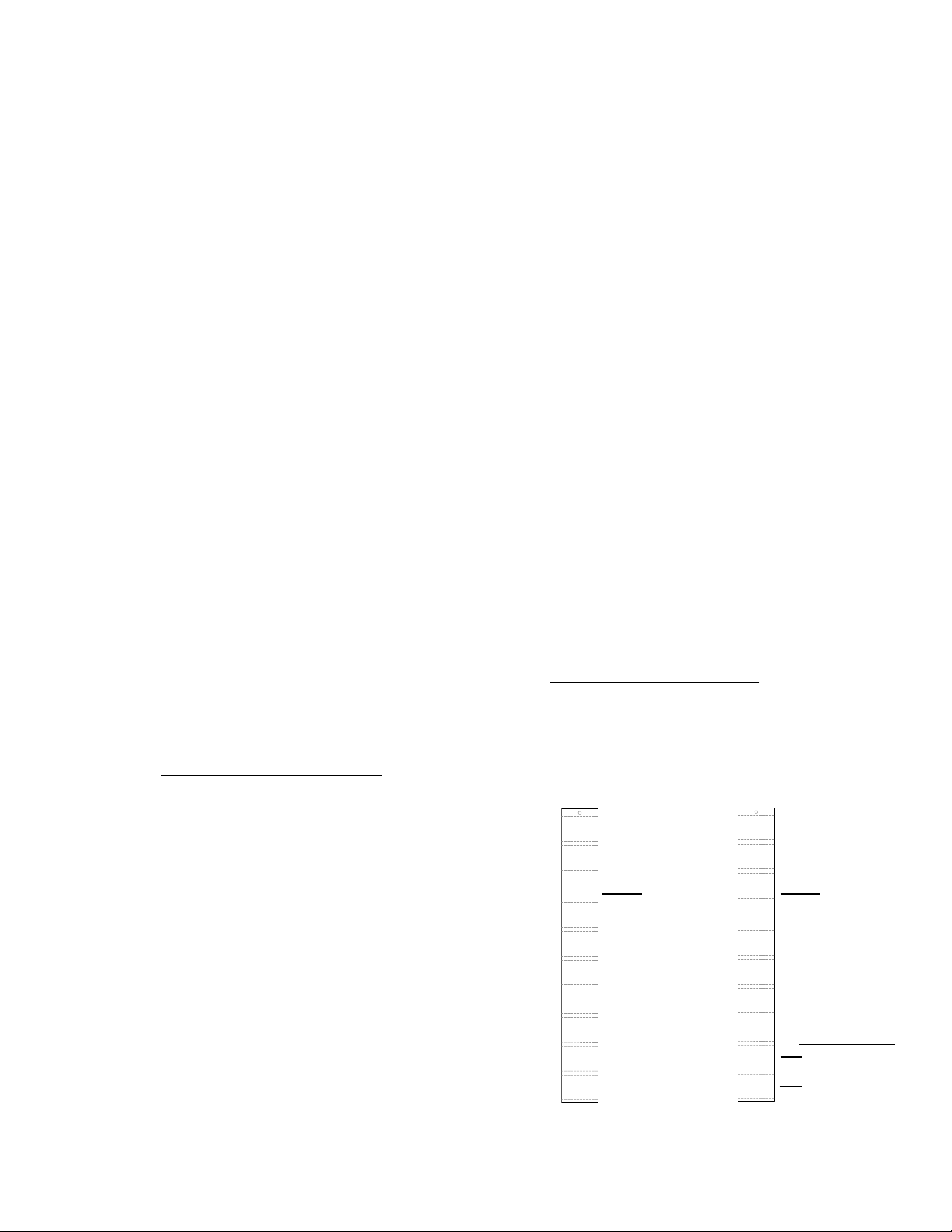
5.0 SYSTEM CONFIGURATION/PROGRAMMING
The following information should be programmed into the NC205 System by qualified administrative personnel prior to general
staff operation. Figure 22 shows the NC250/NC230 Master Station inserts included for system programming. The personnel
responsible for programming should see to it that these inserts are not destroyed, distributed, or changed. Information
programmed after this time should require few changes. During programming, please ensure that all key strokes are deliberate
and that there is a momentary pause between operations.
The numerical selector button LED’s are the first column of
LED selector buttons on the NC250/NC230 Master Station.
The alpha selector button LED’s are the second column of LED
selector buttons. These columns serve dual purposes; the
numerical column serves as zone programming switches, the
alpha column serves as master and station status programming
switches, and both columns serve as normal station selector
buttons.
5.1 MASTER STATIONS
Zoning assignments are for use in controlling the patient,
staff, and duty stations to which the master station may
communicate. They may also be used to control paging, staff
follower, and other system functions. Master stations may be
assigned to one, all, or any combination of the eight zones
supported by the NC205 System. Master stations default to all
eight zones.
In multiple master systems only one conversation to one of
eight audio paths may occur. The stations are pre-wired to
these paths through the default hardware zone number of the
PM261A Selector Card to which it is connected (each card
represents one audio path/hardware zone).
C. To program master status, press the corresponding
alpha key for:
PRESETS = “A” - “H”
These keys indicate the alpha keys used
for preset zones. “A” is the default preset.
BEEP TONE = “I”
When lit, this key indicates that a button
pushed on the master keypad will generate
a short beep tone. To turn off this feature,
press the alpha key so that the LED is off.
PRE-ANNOUNCE TONE = “J”
When lit, this key indicates that a call tone
is introduced at both the station and the
master when a call is placed. To turn off
this feature, press the alpha key so that
the LED is off.
D. To view station fault list, press the “ZONE” button
while in the master programming mode. Stations that
have reported a fault since the last fault scan will
appear with rapidly flashing LED’s. Press the “ZONE”
button again to return to the master programming
mode (display will clear itself after eight seconds).
Refer to Section 5.3 for additional features such as making a
system non-square, adding an expansion keypad, etc. Refer to
Section 5.5 for instructions on adding master stations to a
system.
5.1-1
Entering the Programming Mode
To configure the master, press the “ZONE” key (system must
be on but not being used). A display will appear showing the
pre-programmed zones in the numerical key column. The
status of the master is displayed in the alpha key column. Once
these displays have appeared, the master is in the programming
mode.
A. To select zone presets, press the desired alpha key.
The zones assigned to this alpha preset are then
displayed in the numerical key column (the master will
respond to only these zones). Alpha keys “A” - “H”
are used for these zone presets.
B. To program master zones, press zone key 2 more
times, then press the numerical key that corresponds
to number of the zone. If the zone is programmed, that
number’s LED will light. Pressing the numerical key
again will turn off the LED and unprogram that zone.
A display of “ZONE # 0” indicates that no zones are
programmed (master is off-line). Pressing the “9” key
will set all zones “ON”.
Copyright © TekTone Sound & Signal Mfg., Inc. All Rights Reserved.
5.1-2
Exiting the Programming Mode
To exit the programming mode, press the “RESET” button.
(The display will clear eight seconds after entering the
programming mode.)
0
1
2
3
4
5
6
7
8
9
ZONE
#1
#2
#3
#4
#5
#6
#7
#8
ALL
%
NUMERICAL
KEY COLUMN
INSERT
STATUS
A
PRIVACY
B
PAGE
C
INHIBIT
PRIORITY
D
UPGRADE
BATH
STAND
E
()
ALONE
FAULT
F
DEFEAT
FIRE
G
STAFF
H
STATION
MASTER
I
STATION
J
ALPHA
KEY COLUMN
%
%
%
INSERT
MASTER FUNCTIONS
BEEP TONE
PRE-ANNOUNCE
FIG. 22: NC250/230 Programming Inserts
IL600 NC205 Tek-DIGICARE® Manual • 29
Page 40

5.2 PATIENT STATIONS
Assign station zone assignments following the procedures
listed below. The NC205 System should be on but not in use
while zone assignments are being entered.
Zoning assignments for each station default to the selector
card number they have been connected to (in the NC260B
Central Equipment or NC262A Central Equipment Expander).
Stations must be assigned to at least one of the eight zones
supported by the NC205 System, but may be assigned to
additional zones, if desired. Zoning assignments are used to
direct station calls to masters that are zoned for those calls.
5.2-1 Entering the Programming Mode
To choose the station to be programmed, press the appropriate
station selector button on the NC250/NC230/NC255. The LED
associated with that selector button will light as the central
equipment establishes communications with the station. Now
press the “ZONE” button. The station LED will extinguish and
a display showing the zones assigned to the station will appear
in the numeric key column; the station’s status will display in
the alpha key column.
To recall what station is being programmed, simply push the
“ZONE” button again. This will temporarily light the LED of
the station originally chosen with a rapid flash. Press the
“ZONE” button again to return to programming (display will
clear after eight seconds).
A. To assign zones, press the numerical key that
corresponds to the number of the desired zone. If the
zone is programmed, that number’s LED will light.
Pressing the numerical key again will turn off the LED
and unprogram that zone. Pressing the “9” key will
toggle the state of all zones.
NOTE: DO NOT assign “ZONE 0” to stations; this will
render them off-line. To reactivate a station that has
been taken off-line, place a call from that station or reassign it to a zone other than “0”. The central equipment
will then validate the station and assign it to all zones.
B. To program station status, press the corresponding
alpha key:
“A” = STATUS
When lit, this key indicates that the station
is in a standard mode of operation; no
special functions (“B” - “I”) have been
assigned. IR254-259 Stations default to
the “A” Status. IR250-253 and IR260A
Stations default to “F” (Fault Defeat) and
“G” (Fire).
“B”= PRIVACY
When lit, this key indicates that audio
communications from the station are
inhibited. If a call originates from the
station, then normal two-way
communications are established. If the
call originates from a master, then no
audio will be heard from the station at the
master, but audio from master will be
heard at station.
“C” = PAGE INHIBIT
When lit, this key indicates that paging
functions (preset, zone, and all-call
paging) are ignored by the station.
“D” = PRIORITY UPGRADE
This key is used to indicate that a station’s
Routine call has been upgraded to the
Priority level.(Used for IR250-IR253 and
IR260A only).
“E” = BATH (STAND ALONE)
This key is used to mark devices
(Emergency Call Stations, Smoke
Detector Contacts, etc.) as stand
alone bath/emergency stations.
These stations will generate medium
priority (EMERGENCY) calls. By
default, stand alone stations that are
not marked as BATH/STAND ALONE
will generate high priority (CODE or
FIRE) calls.
“F” = FAULT DEFEAT
This key is used to disable the central
equipment’s fault scan for the station. It
can be used to temporarily mask a faulty
station while repairs are underway. This
key must be set for all IR250/IR251/
IR252/IR253, IR260A and stand alone
devices.
“G” = FIRE
When lit, this key indicates that high
priority calls from this station are
recognized as FIRE calls. (NOTE: The
NC205 is not listed as a fire alarm system.
It is not intended as a primary indication
means for evacuation.)
“H” = STAFF STATION
This key is used to mark a station as a
STAFF station. The stations will be included
in staff paging and follow functions.
“I” = MASTER STATION
This key is used to assign a selector
button to a master for master-to-master
communications. All masters must have
the same assigned room number (251-
254) available. Refer to Section 5.3-1.
30 • IL600 NC205 Tek-DIGICARE® Manual
Copyright © TekTone Sound & Signal Mfg., Inc. All Rights Reserved.
Page 41
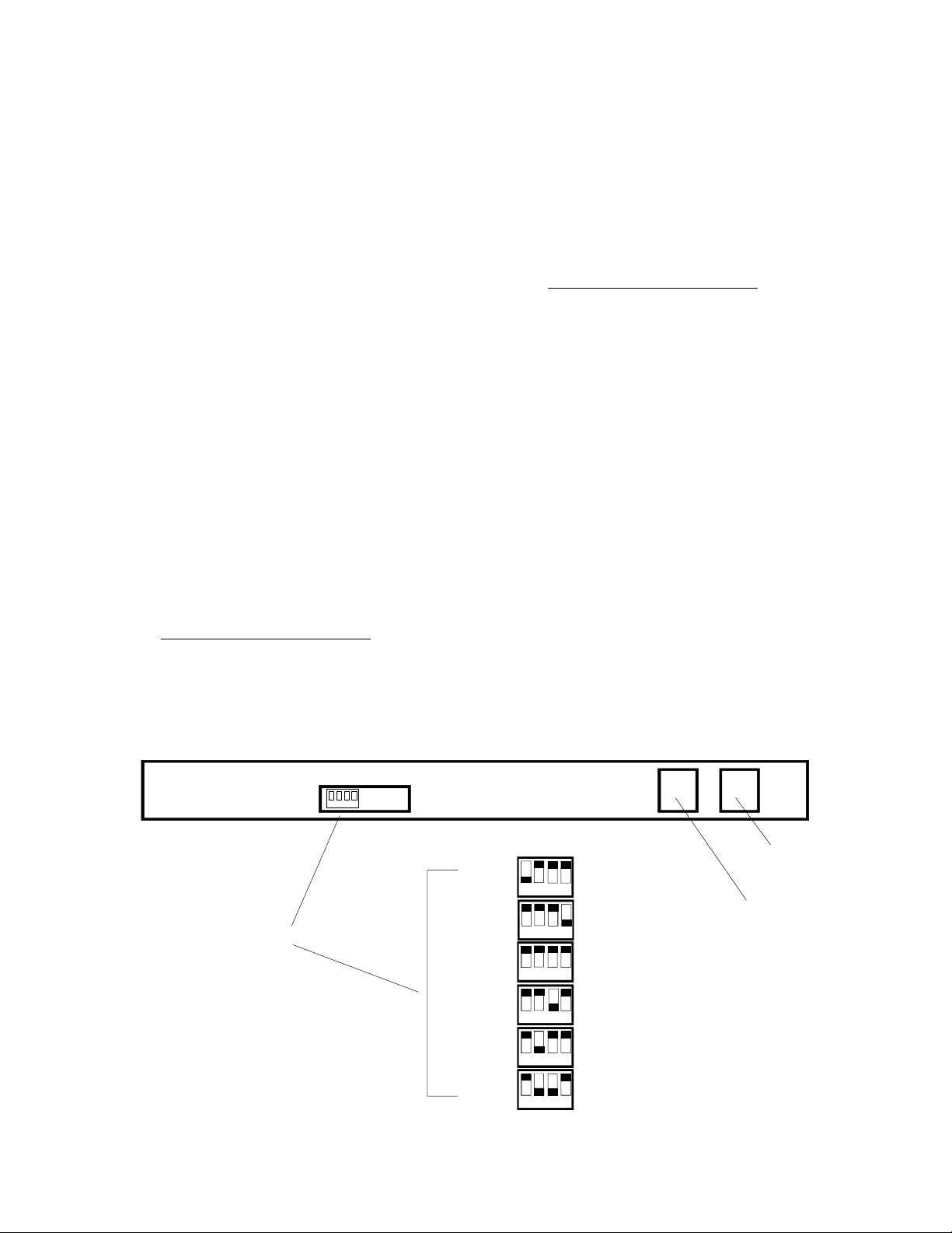
To turn off any feature, simply press its associated
alpha key so that its LED is off. Widely used
programming functions (PRIVACY, PRIORITY
UPGRADE, etc.) should be accomplished by use of the
master function keys so marked.
C. To program a selector key for master-to-master
communication, press “I” to mark the key as a master.
Then press the numerical number of the desired
master (1 through 4). All masters must be programmed
to have their own selector buttons, in addition to
selector buttons representing other masters. For
example, if master-to-master communication is desired
on a system with only two masters, each master must
have one selector button programmed for itself and
another selector button programmed for the other
master. (Note: 251, 252, 253, 254 are the default keys
for master-to-master communication. 251 is used for
master #1, 252 for master #2, and so on.)
NOTES: Master-to-master communications are
restricted to “push-to-talk” only (no handset). See
Section 5.3 for additional details.
Using this method, all master-to-master
communications can be programmed at one master. At
all other masters, the same buttons are programmed
automatically for each master.
5.2-2
Exiting the Programming Mode
To exit the programming mode, press the “RESET” button.
The “RESET” LED will flash until the information has been
stored.
5.3 MASTER KEY PROGRAMMING/CONFIGURATION
The NC250/NC230 Master Stations provide extended features
to allow non-square system configurations, easy keypad
expansion, and custom key configurations.
This section explains the methods used to accomplish these
functions.
5.3-1 Entering the Programming Mode
NOTE: When erasing the flash memory or adding an expansion
keypad, custom configurations (“non-square” and/or “specific
selector buttons”) must be reprogrammed. During
programming, the fault light may illuminate momentarily–a
normal condition.
To place a master station into the programming mode, turn
on (down) the programming switch SW4, as shown in Figure
23. The following features are then available:
A. To reset a master station to default values (erase flash
memory), turn SW4 on, toggle SW1, wait for “TALK”
LED to light (indicating proper operation) and turn
SW4 off.
By default, masters begin room numbering at the first
column’s top selector button and continue from top
to bottom, left to right, until all keys have been
numbered (including all expansion keypads). Other
default values include PRESET “A” on, BEEP TONE
on, and PRE-ANNOUNCE TONE off.
1 2 3 4
MASTER CONTROL DIP SWITCH
MASTER CONTROL DIP SWITCH
FIG. 23: NC250/230 Master DIP Switch Controls
Copyright © TekTone Sound & Signal Mfg., Inc. All Rights Reserved.
REAR VIEW OF MASTER
ON # MASTER
1 2 3 4
1 2 3 4
1 2 3 4
1 2 3 4
1 2 3 4
1 2 3 4
MASTER CONTROL PORT
(from NC260B Central Equipment)
RESET
PROGRAMMING
MODE ON
MASTER #1
ADDRESS
MASTER #2
ADDRESS
MASTER #3
ADDRESS
MASTER #4
ADDRESS
KEY PAD EXPANSION POR T
(to NC255 Expander)
IL600 NC205 Tek-DIGICARE® Manual • 31
Page 42

B. To add an expansion keypad (NC255) connect to
master and refer to section 5.5-4.
C. To make a master “non-square”, press the ZONE
button, then key in the numerical value of the room
number that the master is to begin from. The TALK
LED will flash and a beep tone will sound when the
information has been accepted. The programming
mode may then be exited.
The term “non-square” means that the master can
begin its selector key assignment from a room number
other than #1. For example, to program an NC250
master (50 key) to begin responding with room number
15, follow the procedures listed above. Key in “0”, “1”,
and “5” for the numerical room value. When completed,
the master will respond to rooms 15 (first selector
button) through 65 (last selector button).
5.4 EQUIPMENT RESET PROCEDURES
5.4-1 Central Equipment
A. To reset the central equipment, remove batteries and
power down the entire system. Then wait 30 seconds
before reapplying power, and reinstall batteries.
B. To reset the flash memory, turn SW1 on and power
down the system per 5.4-1A. Wait until LED’s on the
PM261A Selector Card begin to flash, then turn SW1
off.
C. To disable system programming from masters
(programming lock), turn SW2 on.
5.4-2 Master Stations
A. To reset a master, toggle SW1 (see figure 9).
D. To custom configure a specific selector button, press
the target selector button. Using the numerical key
column, key in the desired value of the room to which
the target selector key will be assigned. The TALK
LED will flash and a beep tone will sound when the
information has been accepted. The programming
mode may then be exited.
The procedure described above can be used to assign
individual out of sequence room numbers to a selector
button. The same procedure is used to mark a selector
button as a master station for master-to-master
communication. Room numbers 251, 252, 253, and 254
are reserved for masters #1, #2, #3, and #4 respectively.
Do not use these room numbers for any other purposes.
(Refer to Section 5.2-1C.)
NOTE: Using this method, the master-to-master
communications must be programmed at each master.
This method is useful if the same buttons for masterto-master communication cannot be used at each
master.
E. To set the system time, flip dipswitch #4 down, press
the “Privacy” button. Enter a two digit hour setting
using the numeric keys, and then enter a two digit
minute setting using the numeric keys. Finally, set
AM or PM by pressing the “0” key for AM or the “1”
key for PM. Return dipswitch #4 to its original position.
The programming mode may then be exited.
B. To erase flash memory, refer to section 5.3-1A.
5.5 EXPANDING/UPGRADING THE
SYSTEM
The NC205 Nurse Call System provides features to allow easy
upgrading and expansion. This section explains the methods
used to accomplish these functions. The system capacity is
128 stations including the master stations.
5.5-1 Adding Central Equipment Expander
A. Inspect and confirm wiring.
B. Disconnect system power at the central equipment
(including backup batteries).
C. Make wiring connections in accordance with Section
2.6 and wiring diagrams.
D. Once wiring has been validated, power may be reapplied
to the system (NC260B, NC262A, and batteries).
E. Reset the flash memory on the NC260B Central
Equipment (Section 5.4-1B).
F. Verify that the activity LED’s on the PM261A Selector
Cards are flashing (see Section 7 for testing).
5.3-2
To exit the programming mode, return SW4 to the off position
and then toggle SW1. This procedure releases the master from
programming mode and then resets it.
Exiting the Programming Mode
32 • IL600 NC205 Tek-DIGICARE® Manual
Copyright © TekTone Sound & Signal Mfg., Inc. All Rights Reserved.
Page 43

5.5-2 Adding Battery Backup
5.5-5
Adding Remote Stations
A. Inspect and confirm wiring.
B. Make wiring connections in accordance with Section
2.6 and wiring diagrams.
NOTE: Battery power should be connected after system
power up. If batteries are drained from use, they should
be removed to power system back up and then reinserted
into connector.
5.5-3
Adding Master Stations
A. Inspect and confirm wiring.
B. Disconnect system power at the central equipment
(including backup batteries) and NC262A expansion
unit.
C. Make wiring connections in accordance with Section
2.6, and wiring diagrams.
D. Verify the DIP switch settings on the master to be
installed. The master’s address should be set to the
next available address (sequentially), the programming
mode should be off, and the reset switch should be up
(off).
E. Once the DIP switch settings and wiring have been
validated, power may be reapplied to the system
(NC260B, NC262A, and batteries).
A. Inspect and confirm wiring.
B. Plug system connector onto station.
C. Place a call from the station. Once the central equipment
has acknowledged the existence of the call, the
master(s) that have been zoned to respond to calls
from the station’s zone will display the call. The call
may then be answered from that master (see Section
7 for testing).
5.5-6
Adding Peripheral Devices
A. Inspect and confirm wiring.
B. Plug peripheral connector onto station.
C. To test SF Series peripherals, activate the call button,
switch, or lever (see Section 7 for testing).
D. To test LI Series peripherals, activate the call(s)
associated with the particular lamp(s) color (see Section
7 for testing).
E. For stand alone devices, verify that the device is
programmed for “PRIVACY” and “FAULT DEFEAT”
at the associated master station.
5.6 VIEWING SYSTEM INFORMATION
F. Reset the NC260B Central Equipment. (See Section
5.4-1).
5.5-4 Adding Master Expanders
A. Inspect and confirm wiring.
B. Verify the DIP switch settings on the master expander
to be installed. The expander’s address should be set
to the next available address (sequentially). The
expander’s type switch SW4 (“on” for NC255), must
be set correctly. (Refer to Section 3.2.)
C. Make wiring connections in accordance with Section
2.6 and NL205-G.
D. Place NC250/230 Master into the programming mode
(see Section 5.3-1, and 5.3-1B).
E. Reset the NC250/NC230 Master (see Section 5.4-2A).
The “TALK” LED will flash and a beep tone will sound
once the master has acknowledged the expansion.
F. Return the master to normal operation (see Section
5.3-2).
The NC205 Nurse Call System provides various methods of
displaying system information. The display pages are timed
out and will clear after eight seconds or when the “RESET”
button is pressed.
5.6-1 Status Display Pages
A. Privacy display - press the “PRIVACY” key. A display
will appear showing stations which have been set for
Privacy with a slow flash of the station’s LED.
B. Priority display - press the “PRIORITY” key. A
display will appear showing stations which have been
set for Personal Attention by a slow flashing of the
station’s LED. Stations which have been upgraded to
Priority will display a rapid flashing of the station’s
LED.
C. Staff display - press the “STAFF” key. A display will
appear showing stations which have staff presence
registered by a slow flashing of the station’s LED.
Stations where staff presence is requested will be
displayed by a rapid flashing of the station’s LED.
Copyright © TekTone Sound & Signal Mfg., Inc. All Rights Reserved.
IL600 NC205 Tek-DIGICARE® Manual • 33
Page 44

5.6-2 Faults
The NC205 System scans for fault conditions approximately
once every six minutes. Faults are displayed through LED’s on
master stations, selector cards, and the central equipment.
Faults are displayed on the NC260B by a row of three LED’s,
(D1, D2, & D3–from left to right) located at the bottom center
of the motherboard. These LED’s will show the detected fault
condition via a fault code.
The PM261A Selector Card displays central equipment faults
with a single red LED. If the LED is off or steadily on, this will
indicate a problem of the central equipment. A flashing LED
indicates normal operation. Note: the flashing of this LED is
irregular.
A. Master station fault - indicated by LED “D1” on
continuously. Other master stations will light their
fault LED’s.
B. Code circuit fault - indicated by LED’s “D1” and
“D2” illuminated. See section 3.3 for indication at
master station.
Code faults are displayed at stations with LI387 Dome
Lights by a slow flashing blue lamp. Only IR254/
IR255/IR256/IR257/IR258/IR259 stations include code
supervision circuitry.
C. Station fault - indicated by LED’s “D1”, “D2”, and
“D3” illuminated. The affected station will be indicated
on the master station via lighting the station’s keypad
LED and the “FAULT” LED will be continuously
illuminated. See section 3.3 for indication at master
station. This could also indicate a nurse or priority line
fault.
All fault indication which has originated from the central
equipment will be indicated by the “FAULT” LED on all master
stations being illuminated continuously. The central equipment
must then be checked for specific fault indication. The “FAULT”
LED flashing at a fast rate will indicate no interrogation from
the central equipment for more than eight (8) seconds, indicating
a central equipment failure.
To view the fault list, press the master’s “ZONE” button twice.
This will display the master’s status information on the first
button press; the second button press will display stations
that have reported faults since the last central equipment fault
scan. They will be indicated by a fast flashing of the station’s
selector LED. This display will clear after eight seconds, or
when the “RESET” button is pressed.
34 • IL600 NC205 Tek-DIGICARE® Manual
Copyright © TekTone Sound & Signal Mfg., Inc. All Rights Reserved.
Page 45

6.0 SYSTEM MAINTENANCE INSTRUCTIONS
The following section provides information regarding NC205 System user serviceable parts and their replacement. Any
equipment not listed in this section is not user serviceable and should not be replaced or repaired by other than qualified service
personnel.
6.1 NC260B CENTRAL EQUIPMENT
& NC262A CENTRAL EQUIPMENT
EXPANDER
No user serviceable parts.
6. 2 PK261A DOME LIGHT POWER SUPPLY
No user serviceable parts.
6.3 NC250/NC230 MASTER STATIONS &
NC255 MASTER STATION EXPANDER
6.3-1 Defective Handset/Cord Replacement
A. To remove cord, grip end of modular plug on
cord firmly and squeeze until cord is easily
pulled away from handset or base.
B. To replace cord, hold end of plug on the cord,
squeeze and push straight into receptacle on
handset or base. Release and plug will click into
place.
B. To replace pillow speaker, hold by end of plug,
squeeze and push straight into the receptacle on
station. Release and plug will click into place.
C. To test pillow speaker, initiate a call. Call-placed
LED should illuminate. Push the reset button to
cancel call (see Section 7.4).
6.4-2
Defective Call Cord Replacement
A. To remove call cord, grip end of plug firmly and
pull straight away from station.
B. To replace call cord, hold by end of plug and
push straight into the receptacle on station.
C. To test call cord, initiate a call. Call-placed LED
should illuminate. Push the reset button to
cancel call (see Section 7.4).
6.5 SF SERIES STATIONS
No user serviceable parts (for SF100C, see Section
6.4-2).
C. To test the handset, place a call to a room station
and attempt communications using the handset
(See Section 7.3).
6.3-2 8 PIN Modular Cord
A. To remove cord, grip end of modular connector
firmly and pull straight away from master station.
Repeat for wall plate connection.
B. To replace cord, hold by end of plug and push
straight into cord jack on station. Plug will click
into place. Repeat for wall plate connection.
C. To test cord, place a call to the station. The
“TALK” LED should illuminate when
communications have been established. Push
the reset button to cancel call (see Section 7.3).
6.4 IR SERIES STATIONS
6.4-1 Defective Pillow Speaker Replacement
A. To remove pillow speaker, grip end of modular
plug firmly and squeeze until cord can easily be
pulled straight away from station.
6.6 LI SERIES DOME/ZONE LIGHTS
6.6-1 Defective Lamp Replacement
A. To remove cover, grip firmly by sides and
squeeze. Pull cover away from plate.
B. To remove lamps, hold by glass bulb, push in
and rotate counter-clockwise, then pull straight
out from metal socket.
C. Remove any bulb covers and replace on new
bulbs.
D. To replace lamps, hold by glass bulb, push in
and rotate clockwise into socket.
E. To test lamps, place calls at all stations necessary
to test all lamp combinations (see Section 7.6).
F. Replace cover.
NOTE: Replace lamps ONLY with TekTone® part
number LI028 or approved equal.
Copyright © TekTone Sound & Signal Mfg., Inc. All Rights Reserved.
IL600 NC205 Tek-DIGICARE® Manual • 35
Page 46

6.7 REPLACEMENT PARTS
TekTone® Part No. Description Used For
CA033 4 pin modular cord, coiled NC250/NC230 Master Station Handset
CA037/7 8 pin modular cord, 7' NC250/NC230 Master Station
CA037 8 pin modular cord, 1' 4" (1.3' ) NC255 Master Station Expander
LI028 28 volt incandescent lamp LI381/LI382/LI383/LI387/LI388A
Dome/Zone Lights
PL467 8 pin modular wall plate NC250/NC230 Master Stations
SF301 call cord with molded push button, 7' IR251/IR252 Standard and
IR255/IR256 Enhanced Patient Stations
SF301/10 same as SF301 with 10' cord IR251/IR252 Standard and
IR255/IR256 Enhanced Patient Stations
SF301G geriatric push button call cord, 7' IR251/IR252 Standard and
IR255/IR256 Enhanced Patient Stations
SF302 dual call cord with molded push buttons, 7' IR251/IR252 Standard and
IR255/IR256 Enhanced Patient Stations
SF302/10 same as SF302 with 10' cord IR251/IR252 Standard and
IR255/IR256 Enhanced Patient Stations
SF302G geriatric dual push button call cord, 7' IR251/IR252 Standard and
IR255/IR256 Enhanced Patient Stations
SF301P pillow speaker with call button & TV controls IR257/IR258 Enhanced Patient Stations
SF301PIR pillow speaker with call button, TV & radio controls IR257/IR258 Enhanced Patient Stations
SF311 call cord with molded push button, IR257/IR258 Enhanced Patient Stations
modular connection, 7'
SF311/10 same as SF311 with 10' cord IR257/IR258 Enhanced Patient Stations
SF311G geriatric/oxygen call cord IR257/IR258 Enhanced Patient Stations
SF312 dual call cord with molded push buttons, IR257/IR258 Enhanced Patient Stations
modular connection, 7'
SF312G geriatric/oxygen dual call cord IR257/IR258 Enhanced Patient Stations
TA030 telephone handset NC250/NC230 Master Stations
36 • IL600 NC205 Tek-DIGICARE® Manual
Copyright © TekTone Sound & Signal Mfg., Inc. All Rights Reserved.
Page 47

7.0 TEST INSTRUCTIONS
The following section provides test instructions for determining correct system operation. It is assumed that the system
hardware and wiring has been inspected and approved, and that the system and its components have been set up according
to Section 5-System Configuration/Programming.
These procedures have been written from the perspective of the user/operator. ONLY QUALIFIED SERVICE PERSONNEL
SHOULD PERFORM REPAIRS AND/OR MAINTENANCE TO THE SYSTEM. Be sure that power is disconnected (DC, then
AC) before attempting to service the system’s main components (central equipment and expanders).
7.1 SYSTEM INSPECTION
7.1-1 Basic Wiring Check
A. Refer to Section 2.5 for wiring instructions.
B. If faulty or misconnected wiring is suspected,
contact a qualified service technician.
7.1-2 Test Setup
Before proceeding with a system test, all system
components should be set to normal operating
conditions as follows:
A. NC255/230/250 Master Station & Expanders:
All function buttons should indicate normal
operation (no LED indication). All selector button
LED’s should be off. The power LED (green)
should be on, the priority LED’s (green, yellow,
red) should be off, the function key LED’s
should be off, and there should be no fault
indication(s).
E. LI Series Corridor Dome/Zone Lights:
Dome lights should not be illuminated and Zone
lights should show no system activity.
7.1-3
Viewing System Faults
Refer to Section 5.6-1 (Status Display Pages), and
Section 5.6-2 (Faults).
7.2 CENTRAL EQUIPMENT AND
EXPANDERS
NOTE: If service is required after reviewing these
steps, a qualified service technician should be alerted.
7.2-1 NC260B Central Equipment
A. Verify that no faults are being displayed on the
NC260B’s motherboard (LED’s D7-D9 as
referenced in Section 5.6-2).
B. Verify that the activity LED’s on all PM261A’s
(selector cards) are flashing.
B. IR250-IR253 Standard Patient Stations and
IR260A Duty Station:
Insert the appropriate call cord in each call cord
receptacle (if applicable). Press the “RESET”
(red) button to cancel any errant calls.
C. IR254-IR259 Enhanced Patient Stations:
Insert the appropriate call cord in each call cord
receptacle (if applicable). Press the “RESET”
(red) button to cancel any errant calls. Station
priority should be set to Routine, and staff
functions should not be active.
D. SF Series Peripheral Stations:
If a call has been activated , reset the station by
returning the call lever/reset switch to the “UP”
or “OFF” position. On SF100C/SF101C Visual
Station, press the “CANCEL” button. On SF250
Presence Stations, the green LED should not be
illuminated.
C. Verify all wiring as per wiring diagrams.
7.2-2 NC262A Central Equipment Expander
A. Verify that the activity LED’s on all PM261A’s
(selector cards) are flashing.
B. Verify all wiring as per wiring diagrams.
7.2-3 PK261A Dome Light Power Supply
A. Verify that the power LED is lit.
B. Verify all wiring as per wiring diagrams.
Copyright © TekTone Sound & Signal Mfg., Inc. All Rights Reserved.
IL600 NC205 Tek-DIGICARE® Manual • 37
Page 48

7.2-4 PM261A Selector Card
A. Verify that the activity LED’s on all PM261A’s
(selector cards) are flashing.
F. Press “RESET” (black) button and check for the
following at both master stations:
1. All signals cancelled.
B. Verify volume setting (see Section 2.7).
C. Verify all wiring as per wiring diagrams.
7.3 MASTER STATIONS AND EXPANDERS
Ensure that the “POWER ON” LED is illuminated on
the master station before performing these tests.
7.3-1 Basic Communications
A. Initiate a call from each master station to a
patient station as described in the Operational
Procedures (Section 4.1-1). Check for the
following at the master station:
1. Room station selector LED is illuminated.
2. “TALK” LED steadily illuminated.
B. Press “TALK” (grey) button and check for the
following at the master station:
1. “TALK” LED steadily illuminated.
2. Audible communications established.
7.3-2
Staff Functions
NOTE: The “STAFF” functions are available only on
IR254-IR259 Patient Stations.
A. Request staff service by selecting a room for
communications, then pressing the “STAFF”
(green) button. Check for the following at the
master station:
1. The room station’s selector button LED is
illuminated.
2. “STAFF” button LED slowly flashing.
Check for the following at the patient station:
1. Green dome light flashing.
2. Green LED on presence station flashing.
Check for following at the duty station in the
same zone:
1. Green dome light flashing (all zone lights).
2. Slow repeating tone signal (1 every 8 seconds).
Check for the following at the patient station:
1. Reset/In-use LED steadily illuminated.
2. Audible communications established.
C. Press “RESET” (black) button and check for the
following at master and patient station:
1. All signals cancelled.
D. Repeat Steps A - C using the handset instead of
the push-to-talk button.
E. Initiate a call to another master station as
described in the Operational Procedures (Section
4.1-1). Check for the following at both master
stations:
1. Master station selector LED is illuminated.
2. “TALK” LED is steadily illuminated.
Check for the following at the called master station:
1. Audible communications can be established
(push-to-talk only, no handset).
7.3-3
B. Press “RESET” (black) button and check for the
following at master station:
1. Room station selector LED and “STAFF”
LED extinguished.
Check for the following at duty stations and
zone lights in the same zone:
1. Green dome light flashing.
C. Cancel the staff service request by selecting the
same room for communications, then pressing
“STAFF” (green) button, and then the “RESET”
(black) button. Check for the following at master
station, room stations, dome lights, zone lights,
and presence stations:
1. All signals cancelled (lights and tones).
Paging Functions
A. Page a zone by pressing the “PAGE” (violet)
button, then pressing a zone number (numerical
key column) as described in the Operational
Procedures (Section 4.1-3). Check for the
following at the master station:
38 • IL600 NC205 Tek-DIGICARE® Manual
Copyright © TekTone Sound & Signal Mfg., Inc. All Rights Reserved.
Page 49

1. “PAGE” LED is illuminated.
2. “ZONE” LED is illuminated.
3. Zone number (numerical key column) is
illuminated.
4. “TALK” LED is illuminated.
2. “STAFF” LED steadily illuminated.
B. Register a staff presence at a presence station
by pressing the “STAFF” button, then place a
routine call from any other patient station in the
same zone. Check for the following at the master
station:
B. Press “TALK” (grey) button and check for the
following at the master station:
1. Audible one-way communications
established to all patient stations within
the selected zone.
Check for the following at all zoned patient stations:
1. Reset/In-use LED steadily illuminated.
2. Audible communication with the master has
been established.
C. Press “RESET” (black) button and check for the
following at master and patient stations:
1. All signals cancelled.
D. Page all preset zones by pressing “PAGE” (violet)
button, and then pressing the “ZONE” (blue)
button. Check for the following at the master
station:
1. “PAGE” LED steadily illuminated.
2. “TALK” LED steadily illuminated.
3. “ZONE” LED steadily illuminated.
1. “FOLLOW” LED steadily illuminated.
2. “STAFF” LED steadily illuminated.
3. The room station’s selector LED is slowly
flashing.
4. Low priority LED (green) steadily illuminated.
5. Slow repeating tone (1 every 8 seconds).
Check for the following at the patient station to
which the staff presence is registered:
1. Reset/In-use LED steadily illuminated.
2. Slow repeating tone (1 every 8 seconds).
3. Green dome light on steady.
4. Green LED on presence station steadily
illuminated.
Check for the following at a duty station in the
same zone:
1. Call-placed LED steadily illuminated.
2. Slow repeating tone (1 every 8 seconds).
3. White dome light on steady.
C. Reset the call from the calling patient station and
check for the following:
7.3-4
Check for the following at all zoned patient stations:
1. Reset/In-use LED steadily illuminated.
2. Audible one-way communications with the
master have been established.
E. Press “RESET” (black) button and check for the
following at master and patient stations:
1. All signals cancelled.
Follower Functions
NOTE: This “STAFF FOLLOWER” function is
available only on IR254-IR259 Enhanced Patient
Stations with SF250 Staff Presence Station installed.
There should be no calls waiting on the system.
A. Initiate Staff Follower by pressing “FOLLOW”
(orange) button, then press the “STAFF” (green)
button. Check for the following at the master
station:
1. “FOLLOW” LED steadily illuminated.
1. All signals cancelled except the “STAFF”
(green) LED on the presence station and
green dome light.
D. Press the “RESET” (black) button at the master
station and check for the following:
1. “FOLLOW” LED extinguished.
2. “STAFF” LED extinguished.
3. Low priority LED (green) extinguished.
E. Cancel the staff presence at the presence station
by pressing the “STAFF” button. Check for the
following:
1. All signals cancelled.
F. Initiate staff follow function to a specific room
by pressing the “FOLLOW” (orange) button,
then push a room station selector button of a
known room/station. Check for the following at
the master station (Note: this particular follower
function is available for IR250-IR260A Series
Stations):
Copyright © TekTone Sound & Signal Mfg., Inc. All Rights Reserved.
IL600 NC205 Tek-DIGICARE® Manual • 39
Page 50

1. “FOLLOW” LED steadily illuminated.
2. LED illumination of room station to be
followed to.
G. Place a routine call from any other patient station
in the same zone. Check for the following at the
patient station to which calls are being sent:
1. Reset/In-use LED steadily illuminated.
2. Slow repeating tone (1 every 8 seconds).
Check for the following at the master stations:
1. Low priority LED (green) steadily illuminated.
2. Slow repeating tone (1 every 8 seconds).
3. The room station’s selector button LED is
slowly flashing.
Check for the following at the duty station in the
same zone:
1. Call-placed LED steadily illuminated.
2. White dome light on steady.
Check for the following at the master station:
1. Low priority LED (green) steadily
illuminated.
2. The room station’s selector button LED is
slowly flashing.
3. Slow repeating tone (1 every 8 seconds).
B. Press the “TALK” (grey) button on the master
station and verify that audible communications
to the calling station is established. Then press
the “RESET” (black) button. Check for the
following at the master station:
1. Low priority LED (green) remains illuminated.
2. The room station’s selector button LED
remains flashing.
3. Slow repeating tone (1 every 8 seconds).
7.3-5
1. Call-placed LED steadily illuminated.
2. Slow repeating tone (1 every 8 seconds).
3. White dome light on steady.
H. Press “RESET” (black) button to toggle off.
Check for the following:
1. All signals cancelled (except incoming call).
I. Press “TALK” (grey) button. Check for the
following at the master:
1. Communication with calling station
established.
J. Press “RESET” (black) button. Check for the
following:
1. All signals cancelled.
Priority Upgrade
NOTE: The “PERSONAL ATTENTION” priority is
available only on IR254-IR259 Enhanced Patient
Stations. For IR250-IR253 and IR260A Standard and
Duty Stations go to step C and place a call.
C. Select the calling room (flashing selector button
LED) and then press the “PRIORITY” button
and then press the “RESET” (black) button.
Check for the following at the master station:
1. Medium priority LED (amber) is steadily
illuminated.
2. The room station’s selector button LED is
flashing.
3. Repeating tone (1 every second).
Check for the following at the patient station:
1. Call-placed LED and white dome light steadily
illuminated on IR250-IR253.
2. Call-placed LED steadily illuminated and
white dome light flashing on IR254-IR259.
D. Repeat Step B. Check for the following at master
station:
1. Medium priority LED (amber) is steadily
illuminated.
2. The room station’s selector button LED is
flashing.
3. Repeating tone (1 every second).
There should be no calls waiting on the system.
A. Upgrade the call priority of a station to Personal
Attention by first selecting a station (IR254IR259), and then pressing the “PRIORITY”
(yellow) button. Then press the “RESET” (black)
button. Proceed to place a standard call from the
station. Check for the following at the patient
station:
40 • IL600 NC205 Tek-DIGICARE® Manual
E. Repeat Step C. Check for the following:
1. All signals cancelled.
7.3-6 Privacy Functions
See Section 5.2-1 for a description of the Privacy
Function. There should be no calls waiting on the
system.
Copyright © TekTone Sound & Signal Mfg., Inc. All Rights Reserved.
Page 51

A. To place a patient/staff station in the Privacy
Mode, first select a station, and then press the
“PRIVACY” (red) button. Then press the
“RESET” (black) button.
B. Test communications from master station by
pressing “TALK” (grey) button as previously
described. Check for the following at patient/staff
stations:
1. Reset/In-use LED steadily illuminated on
station.
B. Press the select key for the same station and then
press the “TALK” (grey) button on the master
and verify that audible communications to the
calling station have been established. (There
should be no audible communications from the
patient station, only to the patient station.)
Check for the following at the master station:
1. The room station’s selector button LED is
steadily illuminated.
C. To reset the “PRIVACY” mode, press the
“PRIVACY” (red) button. Then press the
“RESET” (black) button. Or if it is desirable to
leave the “PRIVACY” mode active, then just
press the “RESET” (black) button. Check for the
following:
1. All signals cancelled.
7.4 REMOTE STATIONS
NOTE: S tations should be tested one at a time.
1. Call-placed LED steadily illuminated.
2. Reset/In-use LED steadily illuminated.
3. White dome light on steady.
4. Audible communications established.
C. Press “RESET” (black) button. Check for the
following at all stations:
1. All signals cancelled.
D. Remove call cord or pillow speaker from receptacle
on patient stations. Check for the following at the
patient/staff stations:
1. Call-placed LED (on IR255-IR258) and white
dome light slowly flashing.
2. On the IR251 and IR252, the white dome light will
be steadily illuminated.
Check for the following at the master station:
1. Medium priority LED (amber) steadily
illuminated.
2. Repeating tone (1 every second).
3. The room station’s selector button LED is
flashing.
A. Initiate a call on each patient or staff station as
described in the Operational Procedures (Section
4.2). On dual stations, both circuits should be
tested. Check for the following at the calling
patient/staff station:
1. Call-placed LED steadily illuminated.
2. White dome light on steady.
Check for the following at master station:
1. Low priority LED (green) steadily
illuminated.
2. The room station’s selector button LED
slowly flashing.
Check for the following at duty stations in the same
zone:
1. Slow-repeating tone (1 every 8 seconds).
2. White dome light on steady.
Check for the following at duty stations in the same
zone:
1. Emergency LED flashing.
2. Repeating tone (1 every second).
3. Red dome light flashing.
E. Replace call cord. Check for the following at all
stations:
1. All signals cancelled.
F. Upgrade the call priority of a station to Priority (as
explained in Section 7.3-5). Repeat above procedures
A - C. Check for the following at patient stations:
1. Call-placed LED and white dome light slowly
flashing on IR254-IR259.
2. Call-placed LED and white dome light steadily
illuminated on IR250-IR253.
Copyright © TekTone Sound & Signal Mfg., Inc. All Rights Reserved.
IL600 NC205 Tek-DIGICARE® Manual • 41
Page 52

Check for the following at master station:
1. Medium priority (amber) LED steadily
illuminated.
2. Repeating tone (1 every second).
3. The room station’s selector button LED is
flashing.
Check for the following at a duty station in the
same zone:
1. Emergency LED flashing.
2. Repeating tone (1 every second).
3. Red dome light slowly flashing.
G. Reset call at the patient station. Check for the
following at all stations:
1. All signals cancelled.
C. Initiate a call on each emergency station (one at
a time) as described in the Operational Procedures
(Section 4.3). Check for the following at
emergency station:
1. Call-placed LED flashing.
Check for following at associated patient station:
1. Red dome light flashing.
Check for following at master station:
1. The room station’s selector button LED is
flashing.
2. Medium priority LED (amber) steadily
illuminated.
3. Tone signal repeating (1 every second).
H. Upgrade the call priority of the station back to
Routine (as explained in Section 7.3-5).
NOTE: Calls may be placed from IR260A Duty
Stations in the same manner as described above.
7.5 SF SERIES PERIPHERAL DEVICES
SF Series peripheral devices should be tested one at
a time.
A. Initiate a call on each visual station (one at a time)
as described in the Operational Procedures
(Section 4.3). Check for the following at visual
station:
1. Call-placed LED steadily illuminated.
Check for following at master station:
1. The room station’s selector button LED is
flashing.
2. Low priority LED (green) steadily illuminated.
3. Tone signal repeating (1 every 8 seconds).
Check for following at duty station in the same
zone:
1. Call-placed LED steadily illuminated.
2. Tone signal repeating (1 every 8 seconds).
3. White dome light steadily illuminated.
B. Reset each visual station as described in the
Operational Procedures (Section 4.3). Check for
the following at emergency, patient, duty, and
master stations:
Check for following at duty station in the same
zone:
1. Emergency LED flashing.
2. Tone signal repeating (1 every second).
3. Red dome light flashing.
D. Reset each emergency station as described in
the Operational Procedures (Section 4.3). Check
for the following at emergency, patient, duty,
and master stations:
1. All signals cancelled.
E. Initiate a call on each code station (one at a time)
as described in the Operational Procedures
(Section 4.3). Check for the following at code
call:
1. Call-placed LED rapidly flashing.
Check for the following at associated patient
stations:
1. Call-placed LED rapidly flashing.
2. Blue dome light rapidly flashing.
Check for the following at master station:
1. Room station’s selector button LED is
illuminated.
2. High priority LED (red) illuminated
3. Tone signal repeating rapidly.
1. All signals cancelled.
42 • IL600 NC205 Tek-DIGICARE® Manual
Copyright © TekTone Sound & Signal Mfg., Inc. All Rights Reserved.
Page 53

Check for the following at a duty station in the
same zone:
1. Emergency LED rapidly flashing.
2. Tone signal repeating rapidly.
3. Blue dome light rapidly flashing.
F. Reset each code call and check for the following
at code, patient, duty and master stations:
1. All signals cancelled.
G. If fire/smoke detector 2 contacts are used in place
of code stations, they may be tested in the same
manner as code stations. NOTE: High priority
LED (red) on master station will flash rapidly.
All other indications remain the same except red
dome flashing on duty station.
H. Register staff presence on each presence station
as described in the Operational Procedures
(Section 4.3). Check for the following at presence
stations:
1. Staff LED (green) steadily illuminated.
Check for the following at associated patient
stations:
1. Green dome light steadily illuminated.
Check for the following at a duty station in the
same zone:
1. Green dome light steadily illuminated.
I. Cancel staff registration as described in the
Operational Procedures (Section 4.3). Check for
the following at presence, patient, and duty station:
1. All signals cancelled.
7.6 LI SERIES PERIPHERAL DEVICES
A. To set LI Series Dome Lights, individually
place calls at a patient station (Sections 4.2 and 4.3)
that reflect the dome light’s signals. For example:
1. To test the blue lamp, place a code call.
2. To test the red lamp, place an emergency call.
3. To test the white lamp, place a routine call.
4. To test the green lamp, register a staff
presence.
Copyright © TekTone Sound & Signal Mfg., Inc. All Rights Reserved.
IL600 NC205 Tek-DIGICARE® Manual • 43
Page 54

APPENDIX 1.0 NC260B COMMUNICATIONS MODE
1.1 GENERAL
The NC260B supports bidirectional communications between
the Central Equipment and an external communications
modem. The connection of the modem to the Central
Equipment is accomplished through the use of a built-in RS232
port on the Central Equipment. This RS232 port is the same
port that was normally used to support pager and printer
operation with the NC260A with the PM263 attached serial
port card.
Two additional system features are now accomplished
through the use of this port. They are:
A. The ability to program custom room labels, and
B. The ability to accomplish limited system fault
location.
The utilization of the new features can be accomplished both
locally (at the site) or remotely (from a location other than the
site).
Note: If no modem or laptop PC is connected to the serial port
or if cable connection to the serial port is incorrect, the system
will flash LED “D1” seven times at approximately one flash
per half second. If this occurs, the port will be disabled for
this type of usage until the system is reset again.
When removing devices connected to the serial port, the
system must be powered down prior to removal.
The following section provides detailed operation for the
local mode.
A. Connect the prepared null modem cable (Refer to
Figure 24) between the appropriate serial port on
the PC or laptop computer and connector J-13 on
the NC260B motherboard, then turn on S1-5 and S17 (Refer to Figure 26).
B. Turn on the NC205 system and the PC or laptop and
execute the desired terminal emulator program.
C. After the NC260B system has completed its
initialization and has begun its normal scan cycle
(activity LED’s on the selector cards will be blinking
and the fault LED’s will not be on), then place switch
S1-3 on the NC260B motherboard to ON and then
OFF. The microprocessor on the NC260B should
stop its normal operation and automatically transfer
to the communications mode. Verification that the
system has changed modes will be evident in that
the LED’s on the selector cards will not be blinking
and a Help/Menu screen will be presented on the
PC/laptop computer. The NC205 system will remain
in this mode unless one of the following items
occurs:
1. A “Leave Communications” command is
issued from the PC/laptop computer.
2. An automatic “Time Out” occurs due to
system inactivity. (Approximately 2-3
minutes.)
3. A system reset to the NC260B is initiated.
1.2 LOCAL OPERATION
To use the NC260B communications mode locally, the following
items are required:
A. A PC or laptop computer, and
B. A properly prepared null modem cable.
(Refer to Figure 24)
Reference Section 1.4 COMMUNICATION SOFTWARE for
terminal software operation and settings.
J13
J13
NC260B
DB25
2
3
4
5
7
8
NC260B
DB25
2
3
4
5
7
8
TX
RX
RTS
CTS
GND
DCD
TX
RX
RTS
CTS
GND
DCD
OR
Figure 24
DB25
DB9
2
3
4
5
7
8
2
3
4
7
5
8
To
PC or Laptop
Computer
To
PC or Laptop
Computer
1.3 REMOTE OPERATION
To use the NC260B communications mode from a remote
location, the following items are required:
A. SITE REQUIREMENTS
1. An operating NC205 system with the
NC260B and software installed.
2. An external modem attached to connector
J-13 on the NC260B motherboard.
3. A standard commercial phone line attached
to the modem.
B. REMOTE REQUIREMENTS
1. A PC or laptop computer equipped with a
modem capable of operating at 9600 baud.
Reference Section 1.4 Communication
Software for terminal software operation and settings.
2. A standard commercial phone line attached
to the modem.
44 • IL600 NC205 Tek-DIGICARE® Manual
Copyright © TekTone Sound & Signal Mfg., Inc. All Rights Reserved.
Page 55

3. A standard RS232 serial cable. (DO NOT
USE A NULL MODEM CABLE FOR THIS
APPLICATION.)
Save the terminal mode settings as default.
The following section provides detailed operation for the
remote mode.
A. SITE PREPARATION
1. Turn the NC205 system and modem off.
2. Connect one end of the RS232 serial cable
to J-13 on the NC260B motherboard.
3. Connect the other end of the RS232 serial
cable to the modem connector.
4. Connect the phone line to the modem.
5. Turn the NC205 system on.
6. Turn the modem on.
7. Turn on S1-5 and verify that S1-7 is OFF.
(Refer to Figure 26.)
8. Place switch S1-3 ON.
9. Place switch S1-3 OFF.
10. The system is now ready for connection
to a remote computer via of the phone line.
B. REMOTE LOCATION PREPARATION
1. Turn on the PC or laptop computer and
the modem (if external).
2. Verify that a standard commercial phone
line is attached to the modem.
3. Enter into the terminal emulation program
and verify that the following protocol is
set:
a. Data Bits – 8
b. Parity – None
c. Stop Bit – 1
1.4 COMMUNICATION SOFTWARE
There are many software programs that will provide the
protocols necessary to accomplish communication with the
NC260B. Since most computer operating systems are either
Windows 95 or Windows 98, the following section provides
the necessary guidance for using Windows supplied
HyperTerminal.
1. From Windows start HyperTerminal.
2. When prompted, supply the connection name.
3. Configure the communications port as follows:
a. Data Bits – 8
b. Parity – None
c. Stop Bit – 1
d. Flow Control – None
4. Click OK.
5. Select File.
6. Select Properties.
7. Select Settings.
8. Set Emulation to ANSI.
9. Set Backscroll buffer to 0.
10. Select ASCII setup.
Make sure that only the two following boxes are selected:
A. Append line feeds to incoming line ends.
B. Wrap lines that exceed terminal width. Line delay=0.
Character delay=0.
4. Dial the telephone number that is connected to the NC260B at the site.
5. Upon receipt of the incoming call, the
NC260B will answer on the first ring and
acknowledge the answer by displaying a
HELP screen on the PC or laptop computer.
At this point, bidirectional communications are available between the NC260B
Central Equipment and the host computer.
6. After the session is completed, the host
computer operator will issue a “Leave Communications” command. This command
will cause the site modem to disconnect
from the NC260B.
Copyright © TekTone Sound & Signal Mfg., Inc. All Rights Reserved.
IL600 NC205 Tek-DIGICARE® Manual • 45
Page 56

APPENDIX 2.0 SYSTEM OPERATION
2.1 GENERAL
The communications feature available on the NC260B is
intended to be utilized by technicians familiar with the
operation of the NC205 system. All of the user commands
are two characters in length and are text-based.
The general operation in this mode is for the user to enter the
desired two-character command at the prompt, followed by a
carriage return. If no subsequent parameters are required, the
central equipment processor will execute the function. At the
completion of the task, the processor will issue a new command
prompt. If user supplied parameters, such as room labels,
etc., are required, the central equipment processor will issue
a parameter prompt (Par->) once the command has been
entered. The user must then supply the correctly formatted
parameter(s), followed by a carriage return.
In communications mode, the first screen that will be seen on
a PC or laptop computer connected to the NC260B is the
HELP screen. The HELP screen is designed to provide the
user with a list of user commands that can be used to read
and write data between the NC260B and the PC or laptop
computer. Figure 25 depicts what the HELP screen looks
like.
Figure 25
COMMANDS PARAMETERS DESCRIPTION
CS NONE CLEAR SIM CALLS
CV ## # POINT VOLTAGE
DH NONE DISPLAY HELP
DZ NO NE READ ZONE C CODES
EC NON E TOGGLE ECHO
ID NONE DISPLAY ID
LC NONE LEAVE COMM
LI NONE LICENSE
LF NONE TOGGLE LF
MR NONE MONITOR
PD 1, 2, 3, ... DIAGNOSTIC
RC ###, ### READ STTN C CODE
RL ###, ### READ LABEL
SC ###, P SIMULATE CALL
S P D, S, P SET PROTOCOL
WC ###, CCCC WRIT E CODE
WL ###, CCCCCCCC WRITE LABEL
The two-letter command code shown in the COMMANDS
column can be used to perform the listed communications
routines between the NC260B and the PC or laptop computer.
As an example, if the following key sequence were entered:
DH <Enter>, the HELP screen would be displayed on the
attached PC or laptop computer. A brief description for each
of the COMMANDS shown on the HELP page follows:
A. CS – Clears a simulated system call. (See SC)
B. CV – Displays the voltage on the selected call line.
C. DH – Displays the HELP screen.
(Refer to Figure 25)
ID – Displays the copyright information for the
D.
Central Equipment code as well as the version
identifier of the installed code.
F. EC – Toggles the character echo function on and
off.
G.
LI – This command allows the user to review the
software license.
H. LC – Used to terminate the communications mode
and restore NC260B system to the normal scan mode.
I. LF – Toggles the line feed issued by the NC260B
ON and OFF.
J. MR – Allows the NC260B processor to return to its
normal scan cycle with the capability of being placed
back into the communications mode with a single
key press (space bar). If any event occurs while the
system is operating in the monitor mode, the status
of the event will be displayed at the host computer
instead of on the normally attached printer.
K. PD – This command will cause the NC260B to step
through all specified zones and measure the select
line voltages. These voltage measurements are made
with the select line high and low. If any line fails to
indicate the correct voltage, an error will be logged
on the PC or laptop computer screen for the failed
room. When PD is selected, the user is prompted
with two questions. The explanation of these
questions is as follows:
1. MAP? (Y or N) –
a. If the operator selects Y, the system will
scan all of the zones that the system found
during its initial scan.
b. If the operator selects N, the system will
only scan the zone specified by the user.
2. STEP? (Y or N) –
a. If the operator selects Y, the system will
automatically step through each room on
each zone that the system found during its
initial scan.
b. If the operator selects N, the operator will
be able to press any key to step from one
room to the next.
L. RC –This command reads and displays the pager
cap code assigned to a room. A typical entry for
this routine would be:
a. RL <ENTER>
b. PAR-> 001,064 <ENTER>
(Where 001 is the starting room number
and 064 is the ending room number.)
46 • IL600 NC205 Tek-DIGICARE® Manual
Copyright © TekTone Sound & Signal Mfg., Inc. All Rights Reserved.
Page 57
M. RL – This command reads and displays the label
y
assigned to a zone/room and displays the data on
the host PC or laptop computer. A typical entry for
this routine would be:
a. RL <Enter>
b. RRR, QQQ or 101, 005 <Enter> (RRR is the
starting room number and QQQis the
quantity of rooms to read.)
N.
SC – This command allows a simulated call to be
placed to the Master without actually placing a call
from the field. The type of call is selectable. The
proper entry for this command is:
a. SC<Enter>
b. PAR->###, X <Enter>
(###=Point Number)
(X= Priority Code, Fire, Emergency
or Routine)
O. SP–This command is used to set the
communications protocol that the NC260B uses to
communicate with the PC or laptop computer. This
protocol will be applied upon the next system reset,
provided S1-5 and S1-6 are set to the “ON” position
on the NC260B. If S1-5 is the only switch on the
NC260B that is set then the protocol will default to
8,1,N. (i.e. at P> prompt, enter 71E which would result
in 7 data bits, 1 stop bit and parity enabled).
P. WC– This command is used to assign pager cap
codes to either room ID’s or zones.
Note: The default mode is for all calls to be paged
by call type, I.E. all routine calls will go to 401a, all
emergency calls will go to 400c and all code calls
will go to 400d. The default mode will be disabled if
the WC command is used to set cap codes. Resets
will be always sent to cap code 402a, regardless of
the mode used. When WC is selected the operator
is prompted as follows:
been programmed through the “Setup
Page By Room” menu will page to the
cap code they were assigned to, regardless of how the zones are assigned.
Q. WL– This command allows the user to write labels
to any room attached to the NC260B system. The
labels are limited in length to eight (8) characters.
The proper entry for this command is:
a. WL <Enter>
b. ###,CCCCCCCC (Where ### is the room
number and CCCCCCCCis the desired label for that room).
This function overwrites any previously assigned label, including default labels. When
finished entering the desired labels and room
numbers, the user exists this routine by depressing the ENTER key.
Figure 26
ON
12345
OFF
1 - Learn Mode Switch
2 - Me mor
3 - Start Bi-Directional Mode
4 - Reset
5 - Protocol
6 - Protocol
7 - No Modem
Lock
67
S5 S6 Protocol
Off Off 8, 1, 0
On Off 8, 1, N
On On Look in EEPROM*
*If protocol has NOT been set on previous bi-directional
session, the protocol defaults to 8, 1, N.
1. Setup page by room? (Y or N)
a. If the operator selects Y the system
will display the parameter (PAR->)
prompt. A typical entry here would
be: PAR-> 001,406a <ENTER> This
would set selector point number 1 to
page to cap code 406a. After <ENTER> is pressed the next point will be
displayed, continue programming or
press <ENTER>to be returned to the
command prompt.
b. If the operator selects N, the message
“Setup Page By Zone?” Will be displayed. A typical entry here would be:
PAR-> 002,402b <ENTER> This would
set zone number 2 to page to cap code
402b. Note: Any selectors which have
Copyright © TekTone Sound & Signal Mfg., Inc. All Rights Reserved.
IL600 NC205 Tek-DIGICARE® Manual • 47
Page 58

2.2 ERROR CODES AND MESSAGES
Typographical errors, entering the incorrect data, and system
faults can cause certain error codes and messages to appear
on the PC or laptop computer. The following error codes
and explanations are typical:
NOTE:
The following information will be sent to the cap code 402A,
regardless of how the system is programmed. This is done so
that if an event printer is connected to the serial port, this
information will still be printed. Do not use cap code 402A for
pagers, unless you desire resets, ETC to appear on pagers.
ERROR CODE EXPLANATION
ER1 Command entered is not recognized
ER2 The parameters that were entered are not in
the proper format or are otherwise invalid.
ER3 The processor has timed out of the
communications mode. (NOTE: Prior to
timing out, fault LEDs D1-D3 will begin to
cycle. A key press at this point will avert the
time out routine.)
ER4 During diagnostic testing, a select line was
not at least mid-scale (~6v) when not
selected.
ER5 During diagnostic testing, a select line could
not be pulled down near ground potential.
COMM FAULT - Communication Fault
CODE FAULT - Code Fault
STAF FLLW ON - Staff Follow ON
ROOM FLLW ON - Room Follow ON
PAGE BEGIN - Page Begin
TALK INITIATE - Talk Initiate
PROG MODE ON - Program Mode ON
ROUTINE RESET - Routine Reset
EMRGNCY RESET - Emergency Reset
CODE RESET - Code Reset
FIRE CLEARED - Fire Cleared
PRS ATT RESET - Personal Attention Reset
FAULT CLEARED - Fault Cleared
STAF REQ RSET - Staff Request Reset
STAFF OUT - Staff Out
STAF FLLOW OFF - Staff Follow OFF
ROOM FLLW OFF - Room Follow OFF
PAGE END - Page End
TALK TRMINATE - Talk Terminate
PROG MODE OFF - Program Mode OFF
PAG STAF BEGN - Page Staff Begin
48 • IL600 NC205 Tek-DIGICARE® Manual
Copyright © TekTone Sound & Signal Mfg., Inc. All Rights Reserved.
Page 59
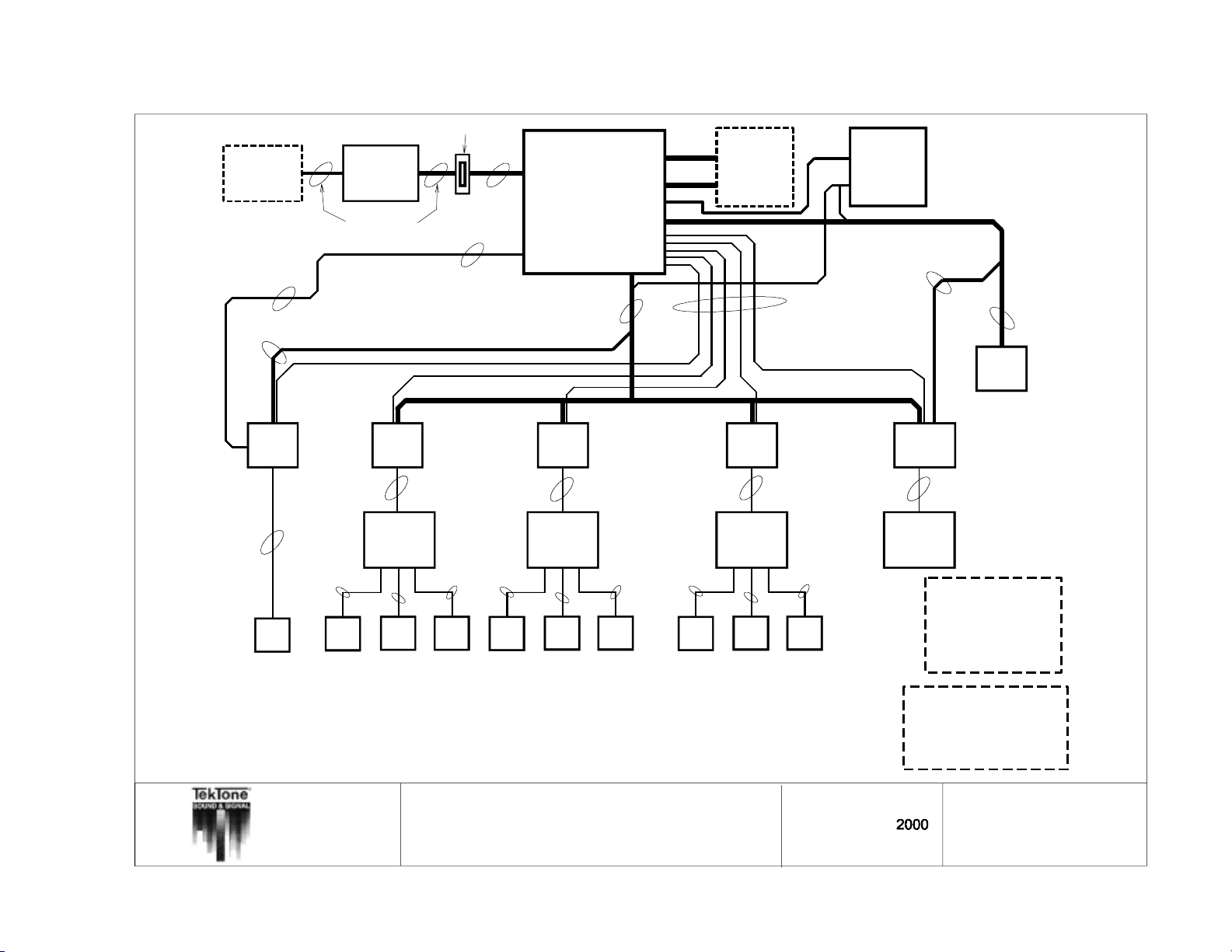
Copyright © TekTone Sound & Signal Mfg., Inc. All Rights Reserved.
NC255/235
MASTER
EXPANDER
1
2 - #18
(
1
o
f
4
s
h
o
w
n
)
8
-
#
2
2
NC250/230
M
A
S
T
E
R
STATION
Modular
Cables Provided
-
#
1
8
Wallplate
8 - #22
See Note A
(up to 6 - #18)
See
Note E
4 - #18
plus
4 - #18
shielded
1 - #18
NC260B
CENTRAL
EQUIPMENT
Ref. NL205-E
7 - #18
See Note B
25 - #22
shielded
1 - #14
1 - #14
6 - #18
NC262
EXPANSION
1 - #18
5 - #22
See Note C
1 - #14
1 - #18
PK261A
Dome Light
Power Supply
7 - #18
NOTE: The 120 VAC power
connections must be wired
so that the NC260B & PK261A
receive power at the same
time.
4 - #18
See
Note D
LI388A
ZONE
LIGHT
7 - #18
See
Note D
IL600 NC205 Tek-DIGICARE
EMERGENCY
STATION
Observe all wire and pin NAMES when connecting equipment!!!
All wire numbers are minimum AWG sizes.
Refer to NL205-H for maximum wiring distances and standard wire colors.
®
Manual • 49
NOTE: Fire indication at the nurse master station is supplementary only.
The NC205 system is not intended for use as a fire alarm evacuation system.
L
I3
8
1
DOME
LIGHT
SF330
SF337C
SF340B
4 - #18
1 - #22
Enhanced Staff
FIRE or
SMOKE
CONTACTS
EMERGENCY
LI387
DOME
LIGHT
7 - #18
4 - #22
IR254 - IR259
and Patient
Stations
3 - #222 - #22
3 - #22
SF330
SF337C
SF340B
STATION
SF250
STAFF
PRESENCE
STATION
All wire must be stranded.
TITLE:
APP:
See Note BSee Note B
LI387
DOME
LIGHT
IR254 - IR259
Enhanced Staff
and Patient
Stations
SF330
SF337C
SF340B
EMERGENCY
STATION
IR254 - IR259
Enhanced Staff
FIRE or
SMOKE
CONTACTS
EMERGENCY
LI387
DOME
LIGHT
7 - #18
4 - #22
and Patient
Stations
3 - #22
SF330
SF337C
SF340B
STATION
3 - #222 - #22
SF250
STAFF
PRESENCE
STATION
2 - #22 3 - #22
SF341B
CODE CALL
STATION
NC205 Block Wiring Diagram w/Enhanced
Stations and Dome Light Conduit Runs
NC205 Nurse Call System
7 - #18
4 - #22
3 - #22
See Note B
SF250
STAFF
PRESENCE
STATION
DRAWN BY:
Drawing #:
REV:
LI387
DOME/ZONE
LIGHT
10 - #18
4 - #22
IR260A
Duty
Station
NC260B ----------- 24 VDC 4A
NC262 ----------- 24 VDC 4A
NC250/NC230 - 18 VDC 650mA
NC255/NC235 -- 5 VDC 50mA
PM261A ----------- 24 VDC 480mA
IR250-IR260A -- 24 VDC 90mA
LI388A ------------- 24 VDC 70mA
SF250/340B/341B/330/337C
---------------- 24 VDC 4mA
LI381/382/383/387
---------------- 24 VDC 80mA
SF100C ------- 24 VDC 60mA
Note A: Flasher Buss wires
Note B: Station Common wires
(Includes 1 twisted-shielded pair)
Note C: Selective wire trunk
Note D: Zone Buss wires
Note E: Master Station wiring
(4 #18 shielded & 4 #18)
MJF
9
DATE:
PAGE:
09/18/2000
NL205-A
Page 60
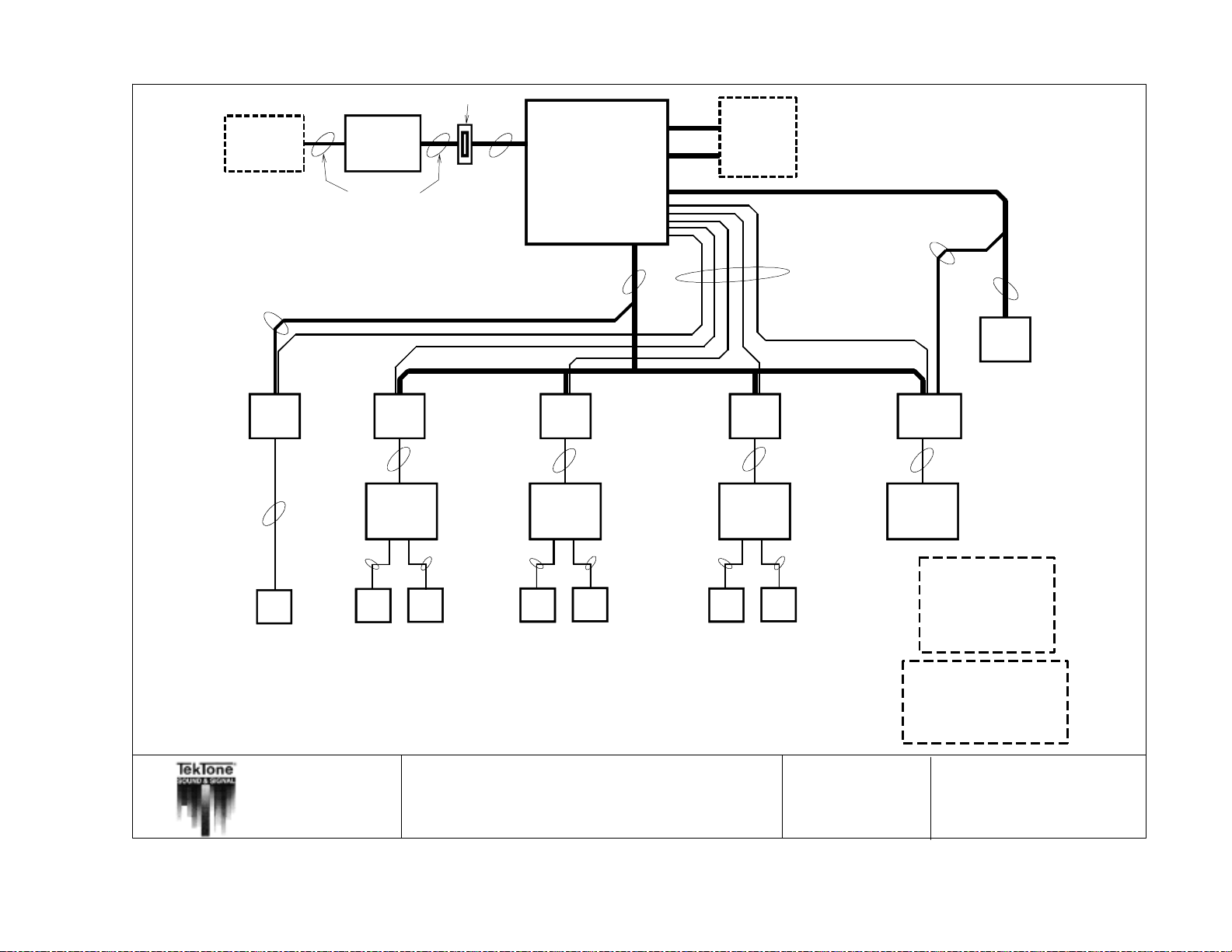
50 • IL600 NC205 Tek-DIGICARE
NC255/235
MASTER
EXPANDER
8
-
#
2
2
(
1
o
f
4
s
h
o
w
NC250/230
M
A
S
T
STATION
Modular
Cables Provided
8 - #22
Wallplate
4 - #18
4 - #18
shielded
See
Note E
plus
NC260B
CENTRAL
EQUIPMENT
n
)
E
R
25 - #22
shielded
1 - #14
7 - #18
NC262
EXPANSION
®
Manual
Copyright © TekTone Sound & Signal Mfg., Inc. All Rights Reserved.
EMERGENCY
Observe all wire and pin NAMES when connecting equipment!!!
All wire numbers are minimum AWG sizes.
Refer to NL205-H for maximum wiring distances and standard wire colors.
NOTE: Fire indication at the nurse master station is supplementary only.
The NC205 system is not intended for use as a fire alarm evacuation system.
3 - #18
L
I3
8
1
DOME
LIGHT
4 - #18
1 - #22
SF330
SF337C
SF340B
STATION
LI382
DOME
LIGHT
8 - #18
3 - #22
IR250 - IR253
Standard Staff
and Patient
Stations
5 - #22 4 - #22
SF330
SF337C
SF340B
EMERGENCY
FIRE or
SMOKE
CONTACTS
STATION
All wire must be stranded.
See Note A
See Note B
Ref. NL205-E
8 - #18
See Note A
See Note B
LI382
DOME
LIGHT
8 - #18
3 - #22
IR250 - IR253
Standard Staff
and Patient
Stations
5 - #22 4 - #22
SF330
SF337C
SF340B
EMERGENCY
FIRE or
SMOKE
CONTACTS
STATION
See Note A
See Note B
LI382
DOME
LIGHT
8 - #18
3 - #22
IR250 - IR253
Standard Staff
and Patient
Stations
5 - #22 4 - #22
SF330
SF337C
SF340B
EMERGENCY
FIRE or
SMOKE
CONTACTS
STATION
5 - #22
See Note C
See Note A
See Note B
5 - #18
See
Note D
7 - #18
See
Note D
LI388A
ZONE
LIGHT
LI387
DOME/ZONE
LIGHT
10 - #18
5 - #22
IR260A
Duty
Station
NC260B ----------- 24 VDC 4A
NC262 ----------- 24 VDC 4A
NC250/NC230 - 18 VDC 650mA
NC255/NC235 -- 5 VDC 50mA
PM261A ----------- 24 VDC 480mA
IR250-IR260A -- 24 VDC 90mA
LI388A ------------- 24 VDC 70mA
SF250/340B/341B/330/337C
---------------- 24 VDC 4mA
LI381/382/383/387
---------------- 24 VDC 80mA
SF100C ------- 24 VDC 60mA
Note A: Flasher Buss wires
Note B: Station Common wires
(Includes 1 twisted-shielded pair)
Note C: Selective wire trunk
Note D: Zone Buss wires
Note E: Master Station wiring
(4 #18 shielded & 4 #18)
TITLE:
APP:
NC205 Block Wiring Diagram w/Standard
Stations and Dome Light Conduit Runs
NC205 Nurse Call System
DRAWN BY:
MJF
Drawing #: 2001
REV:
7
DATE:
PAGE:
09/18/2000
NL205-B
Page 61
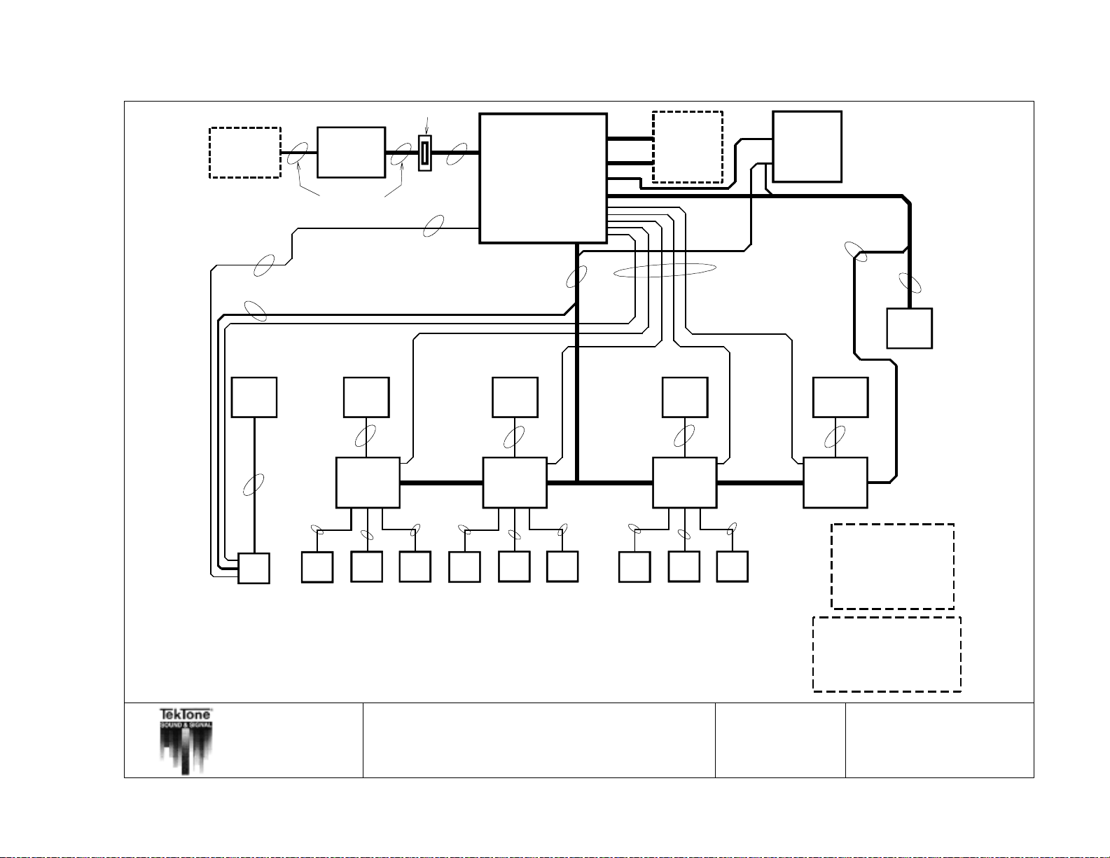
Copyright © TekTone Sound & Signal Mfg., Inc. All Rights Reserved.
NC255/235
MASTER
EXPANDER
1
2 - #18
(
1
o
f
4
s
h
o
w
n
)
8
-
#
2
2
NC250/230
M
A
S
T
E
R
STATION
Modular
Cables Provided
-
#
1
8
Wallplate
8 - #22
See Note A
(up to 6 - #18)
See
Note E
4 - #18
plus
4 - #18
shielded
1 - #18
NC260B
CENTRAL
EQUIPMENT
Ref. NL205-E
7 - #18
See Note B
25 - #22
shielded
1 - #14
1 - #14
6 - #18
NC262
EXPANSION
1 - #18
5 - #22
See Note C
1 - #14
1 - #18
PK261A
Dome Light
Power Supply
7 - #18
NOTE: The 120 VAC power
connections must be wired
so that the NC260B & PK261A
receive power at the same
time.
4 - #18
See
Note D
LI388A
ZONE
LIGHT
7 - #18
See
Note D
IL600 NC205 Tek-DIGICARE
Observe all wire and pin NAMES when connecting equipment!!!
All wire numbers are minimum AWG sizes.
Refer to NL205-H for maximum wiring distances and standard wire colors.
®
Manual • 51
NOTE: Fire indication at the nurse master station is supplementary only.
The NC205 system is not intended for use as a fire alarm evacuation system.
L
I3
8
1
DOME
LIGHT
2
-
#
2
2
SF330
SF337C
SF340B
EMERGENCY
STATION
Enhanced Staff
EMERGENCY
F
IR
E
o
r
SMOKE
CONTACTS
LI387
DOME
LIGHT
4 - #22
IR254 - IR259
and Patient
Stations
3 - #22
SF330
SF337C
S
F
3
4
0
B
STATION
TITLE:
See Note B
3 - #222 - #22
SF250
STAFF
PRESENCE
STATION
Enhanced Staff
FIRE or
SMOKE
CONTACTS
All wire must be stranded.
NC205 Block Wiring Diagram w/Enhanced
Stations and Conduit Runs to Stations
APP:
NC205 Nurse Call System
LI387
DOME
LIGHT
4 - #22
IR254 - IR259
and Patient
Stations
3 - #22
SF330
SF337C
SF340B
EMERGENCY
STATION
PRESENCE
STATION
3 - #222 - #22
SF250
STAFF
IR254 - IR259
Enhanced Staff
See Note B
CODE CALL
STATION
and Patient
2 - #22 3 - #22
SF341B
EMERGENCY
LI387
DOME
LIGHT
4 - #22
Stations
3 - #22
SF330
SF337C
SF340B
STATION
See Note B
SF250
STAFF
PRESENCE
STATION
DRAWN BY:
Drawing #:
REV:
LI387
DOME/ZONE
LIGHT
4 - #185 - #22
IR260A
Duty
Station
NC260B ----------- 24 VDC 4A
NC262 ----------- 24 VDC 4A
NC250/NC230 - 18 VDC 650mA
NC255/NC235 -- 5 VDC 50mA
PM261A ----------- 24 VDC 480mA
IR250-IR260A -- 24 VDC 90mA
LI388A ------------- 24 VDC 70mA
SF250/340B/341B/330/337C
---------------- 24 VDC 4mA
LI381/382/383/387
---------------- 24 VDC 80mA
SF100C ------- 24 VDC 60mA
Note A: Flasher Buss wires
Note B: Station Common wires
(Includes 1 twisted-shielded pair)
Note C: Selective wire trunk
Note D: Zone Buss wires
Note E: Master Station wiring
(4 #18 shielded & 4 #18)
MJF
DATE:
09/18/2000
2002
8
PAGE:
NL205-C
Page 62
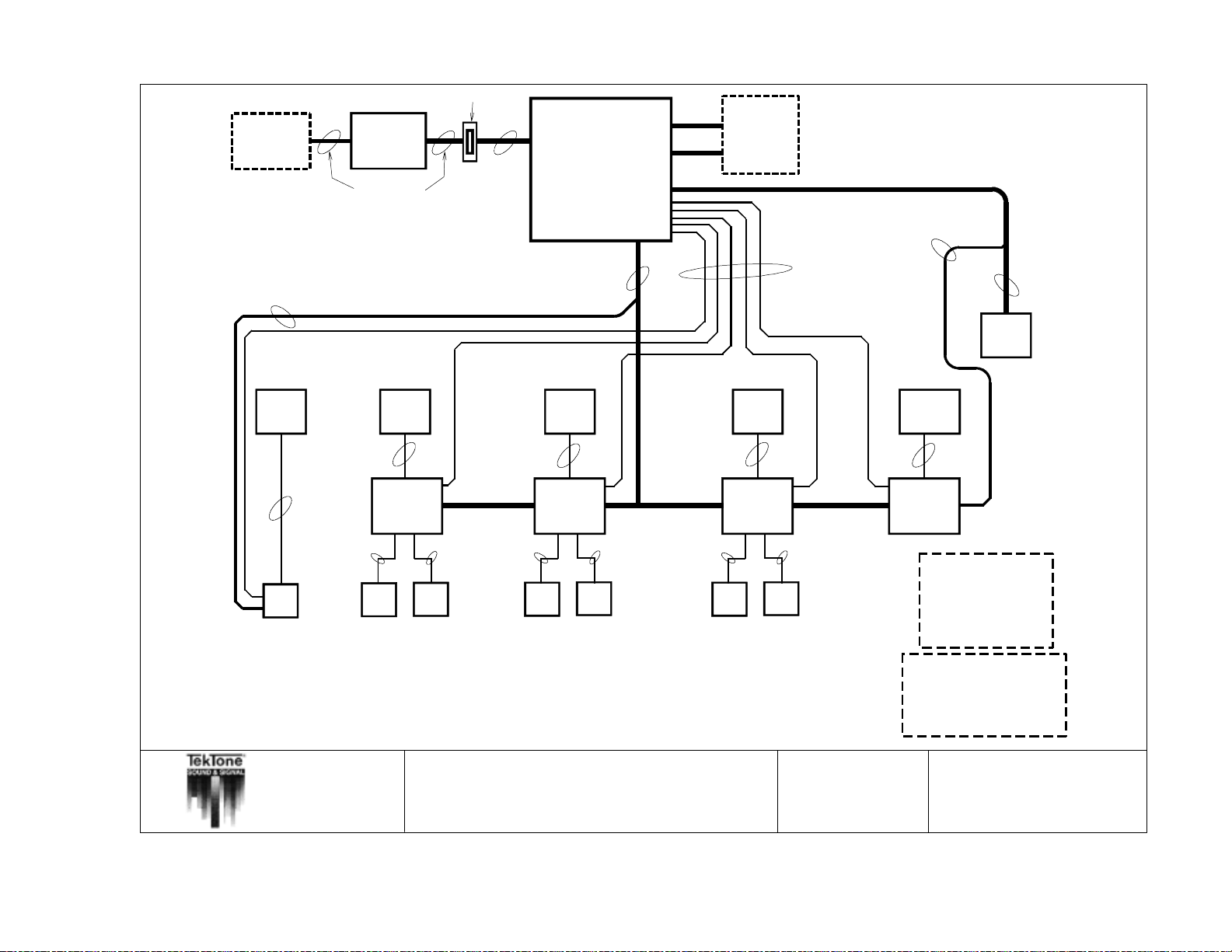
52 • IL600 NC205 Tek-DIGICARE
NC255/235
MASTER
EXPANDER
8
-
#
2
2
(
1
o
f
4
s
h
o
w
NC250/230
M
A
S
T
E
STATION
M
o
d
u
Cables Provided
8
-
Wallplate
#
2
2
See
Note E
4 - #18
plus
4 - #18
shielded
NC260B
CENTRAL
EQUIPMENT
n
)
R
la
r
25 - #22
shielded
1 - #14
7 - #18
NC262
EXPANSION
®
Manual
Copyright © TekTone Sound & Signal Mfg., Inc. All Rights Reserved.
Observe all wire and pin NAMES when connecting equipment!!!
All wire numbers are minimum AWG sizes.
Refer to NL205-H for maximum wiring distances and standard wire colors.
NOTE: Fire indication at the nurse master station is supplementary only.
The NC205 system is not intended for use as a fire alarm evacuation system.
3 - #18
L
I3
8
1
DOME
LIGHT
2 - #22
SF330
SF337C
SF340B
EMERGENCY
STATION
LI382
DOME
LIGHT
3 - #22
IR250 - IR253
Standard Staff
and Patient
Stations
5 - #22 4 - #22
SF330
SF337C
SF340B
EMERGENCY
FIRE or
SMOKE
CONTACTS
STATION
All wire must be stranded.
See Note A
See Note B
Ref. NL205-E
8 - #18
See Note A
See Note B
LI382
DOME
LIGHT
3 - #22
IR250 - IR253
Standard Staff
and Patient
Stations
5 - #22 4 - #22
SF330
SF337C
SF340B
EMERGENCY
FIRE or
SMOKE
CONTACTS
STATION
See Note A
See Note B
LI382
DOME
LIGHT
3 - #22
IR250 - IR253
Standard Staff
and Patient
Stations
5 - #22 4 - #22
SF330
SF337C
SF340B
EMERGENCY
FIRE or
SMOKE
CONTACTS
STATION
5 - #22
See Note C
See Note A
See Note B
5 - #18
See
Note D
7 - #18
LI388A
ZONE
LIGHT
LI387
DOME/ZONE
LIGHT
4 - #18
5 - #22
IR260A
Duty
Station
NC260B ----------- 24 VDC 4A
NC262 ----------- 24 VDC 4A
NC250/NC230 - 18 VDC 650mA
NC255/NC235 -- 5 VDC 50mA
PM261A ----------- 24 VDC 480mA
IR250-IR260A -- 24 VDC 90mA
LI388A ------------- 24 VDC 70mA
SF250/340B/341B/330/337C
---------------- 24 VDC 4mA
LI381/382/383/387
---------------- 24 VDC 80mA
SF100C ------- 24 VDC 60mA
Note A: Flasher Buss wires
Note B: Station Common wires
(Includes 1 twisted-shielded pair)
Note C: Selective wire trunk
Note D: Zone Buss wires
Note E: Master Station wiring
(4 #18 shielded & 4 #18)
See
Note D
TITLE:
APP:
NC205 Block Wiring Diagram w/Standard
Stations and Conduit Runs to Stations
NC205 Nurse Call System
DRAWN BY:
Drawing #:
REV:
MJF
2003
7
DATE:
PAGE:
09/18/2000
NL205-D
Page 63
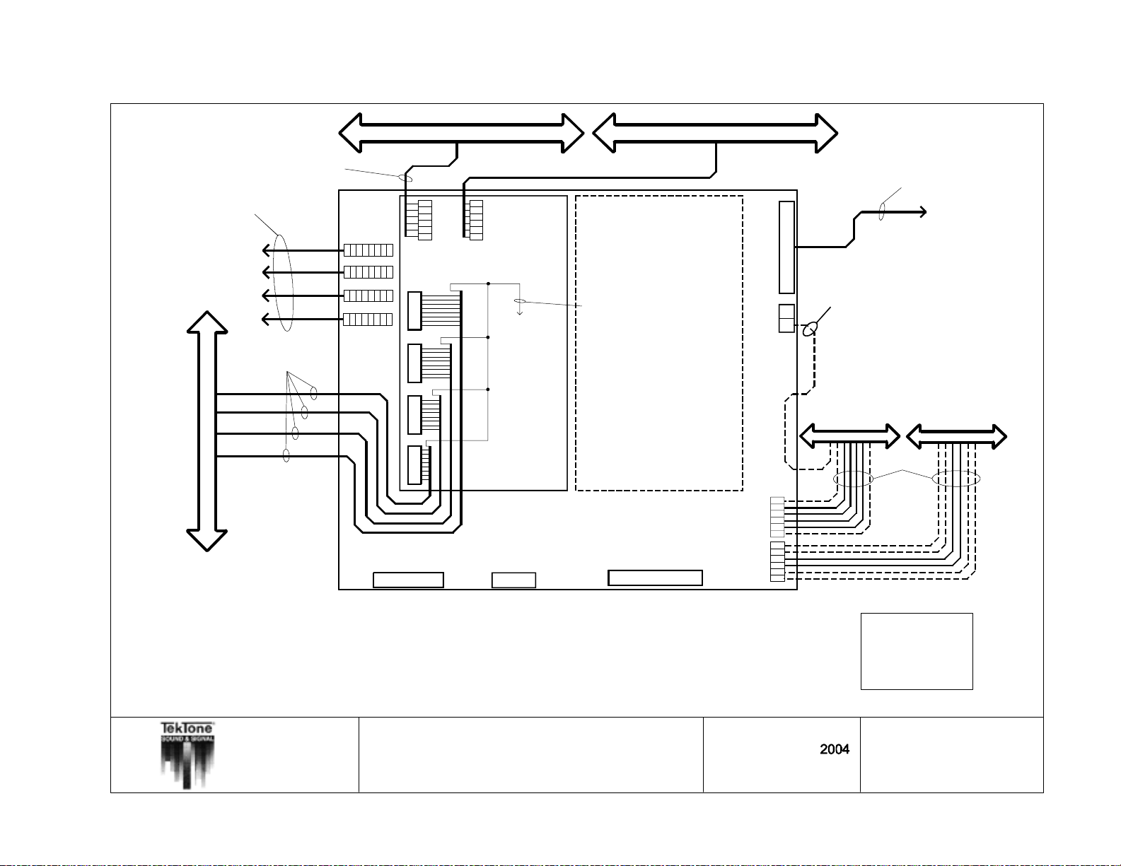
Copyright © TekTone Sound & Signal Mfg., Inc. All Rights Reserved.
To Master Stations
(4#18 shielded and 4#18
per master station)
IL600 NC205 Tek-DIGICARE
SELECTIVE WIRE TRUNKS
STATION COMMONS BUSS
(1 Twisted Shielded Pr. #18 and 4#18)
MASTER #1
321
6
5
7
4
8
MASTER #2
321
6
5
87
4
MASTER #3
8765432
MASTER #4
8765432
Fault
Control In
Power On
Control Out
Digital Audio In
System Ground
9#22
Digital Audio Out
SYSTEM POWER
4 PIN HEADER
STATION COMMONS BUSS
25 #22 Shielded (CT261)
1
2
3
4
5
6
1
1
25-32
+18 VDC
17-24
1-8 9-16
ORANGE
RED
VIOLET
BROWN
GREEN
BLUE
1
AUDIO (+)
AUDIO (-)
2
3
STATION GROUND
4
STATION POWER
NURSE (CONTROL #0)
5
6
PRIORITY (CONTROL #1)
PM261A Selector Card #1 PM261A Selector Card #2
NOTE: Common connectors do not
follow standard color code, but are
ordered to match color to color with
station common connectors.
NOTE: Common wires and Selective wire
connected to an individual station must
come from the same PM261A Selector
card. DO NOT cross-connect from one
selector card to another.
NOTE: SELECTIVE GROUND WIRE. Run
1 additional #22 selective (ground) wire
(within selective wire trunk) per every 8
selective wires. This wire should be connected to the NC260B chassis ground lug.
The other end of this conductor should be
continuous to the end of the selective wire
trunk run, which must be left floating and
isolated.
NC260B Central Equipment
(PM260B)
BATTERY BACKUP
(BA002K)
2 PIN HDR.
SERIAL DATA PORT
DB25 CONNECTOR
Central Equipment
Ground
ZONE POWER
ZONE DATA 0
ZONE DATA 1
ZONE DATA 2
ZONE SELECT
SYSTEM GROUND
FLASHER POWER
FAST FLASH
FAST FLASH
SLOW FLASH
SLOW FLASH
SYSTEM GROUND
Expansion Port
DB25 CONNECTOR
1
2Power
1
2
3
4
5
6
1
2
3
4
5
6
To NC262A CE Expander
This line is used for Zone Buss when
PK261A Dome Lamp Power Supply is not
installed in system.
*** 8 zone light maximum***
without PK261A Dome Lamp Power Supply
reference NL205-N for details
*** 16 zone light maximum***
with PK261A Dome Lamp Power Supply
ZONE BUSS
Up to 6 - #18
FLASHER BUSS
(If used.)
®
Manual • 53
NOTES:
1. *ALL FIELD WIRING SHOULD BE TERMINATED OUTSIDE OF SYSTEM EQUIPMENT ENCLOSURES.*
2. *8 patient station MAXIMUM per station common cable run.*
3. Refer to NL205-H for maximum wiring distances and standard wire colors.
4. Observe wire and pin NAMES when connecting equipment!
5. All wire numbers are minimum AWG sizes. All wire must be stranded.
6. Audio shields should be connected to the NC260B Ground Lug. These shields should be continuous
until the end of the run, where they will be taped back and isolated. Any unused wires in the common
cables or in the selective line trunk cables should be connected to the NC260B Ground Lug and have
their field end isolated. If selective line cable has a shield, the shield should be connected to the NC260B Ground Lug with its field end isolated.
TITLE:
APP:
NC260B Central Equipment Wiring
NC205 Nurse Call System
DRAWN BY:
Drawing #:
REV:
MJF
13
PIN# STANDARD WIRE COLOR
1
BROWN
2
RED
3
ORANGE
4
YELLOW
5
GREEN
6
BLUE
VIOLET
7
8
GRAY
WHITE
9
BLACK
10
DATE:
PAGE:
11/3/1999
NL205-E
Page 64
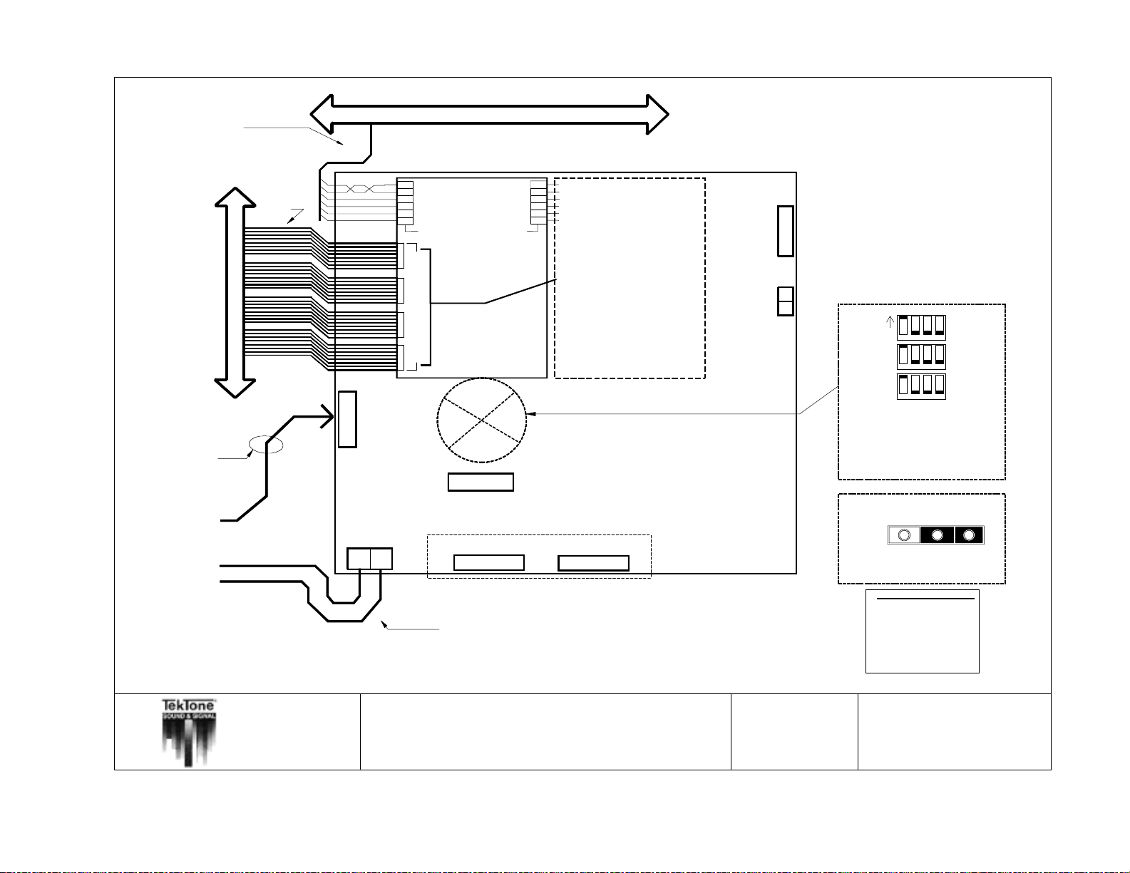
54 • IL600 NC205 Tek-DIGICARE
(includes 1 shielded-twisted pair
®
Manual
25 conductor
#22 shielded
Copyright © TekTone Sound & Signal Mfg., Inc. All Rights Reserved.
From NC260B
#18
for AUDIO + and AUDIO - )
#22
SELECTIVE WIRE TRUNKS
STATION COMMONS BUSS
*** 8 dome light MAXIMUM per station common cable run ***
1
2
3
4
5
PRIORITY (CONTROL #1)
6
STATION COMMONS
STATION SELECTIVES
1-8 9-16 17-24 25-32
CENTRAL
EQUIPMENT
EXPANSION
DB25
PORT
EXPANSION
COMMONS
Expansion Ground
Expansion Power
12
PM261A
1
2
3
4
5
6
AUDIO (+)
AUDIO (-)
STATION GROUND
STATION POWER
NURSE (CONTROL #0)
SELECTOR CARD #1
3 PIN HEADER
POWER SELECT
USED ON NC262A ONLY
SYSTEM POWER
4 PIN HEADER
ORANGE
RED
VIOLET
BROWN
GREEN
BLUE
NOTE: SELECTIVE GROUND WIRE
Run 1 additional #22 selective (ground)
wire (within selective wire trunk) per
every 8 selective wires. This wire
must be connected to NC260B or
NC262A chassis ground lug. The
other end of this conductor must be
continuous to end of selective wire
trunk, which must be left floating and
isolated.
NOTE: Common
connectors do not
follow standard
color code, but are
ordered to match
color to color with
station connectors.
BACKUP BATTERY
2 PIN HEADER
PM261A
SELECTOR CARD #2
NOTE: Audio shields must be connected to a dedicated earth ground with the
system common at one point. These shields must be continuous until the end of
the run, where they will be taped back and isolated. Any unused wires in the
common control cables or in the selective line cables must be grounded at the
central equipment with their other ends left floating. If selective line cable has a
shield, the shield must be grounded at the central equipment as well.
DB25
1
2
Expansion Address DIP Switches
ON
Shown as Expansion #1
1234
1234
1234
SW1
SW2
SW3
ALL '1's ON = Expansion #1
All other switches
should be "OFF"
Power Select Header
LOCAL POWER
NC262A
123
#14
Observe wire and pin NAMES when connecting equipment !!!
NOTE: All wire numbers are minimum AWG sizes.
All wire must be stranded.
TITLE:
NC262A Central Equipment Expansion Wiring
APP:
NC205 Nurse Call System
* ALL FIELD WIRING MUST BE TERMINATED
OUTSIDE OF SYSTEM EQUIPMENT ENCLOSURES *
Refer to NL205-H for maximum wiring
distances
DRAWN BY:
REV:
MJF
9
PIN# STANDARD WIRE COLOR
BROWN
1
2
RED
ORANGE
3
4
YELLOW
5
GREEN
6
BLUE
VIOLET
7
GRAY
8
WHITE
9
10
BLACK
DATE:
PAGE:
09/18/2000
NL205-F
Page 65
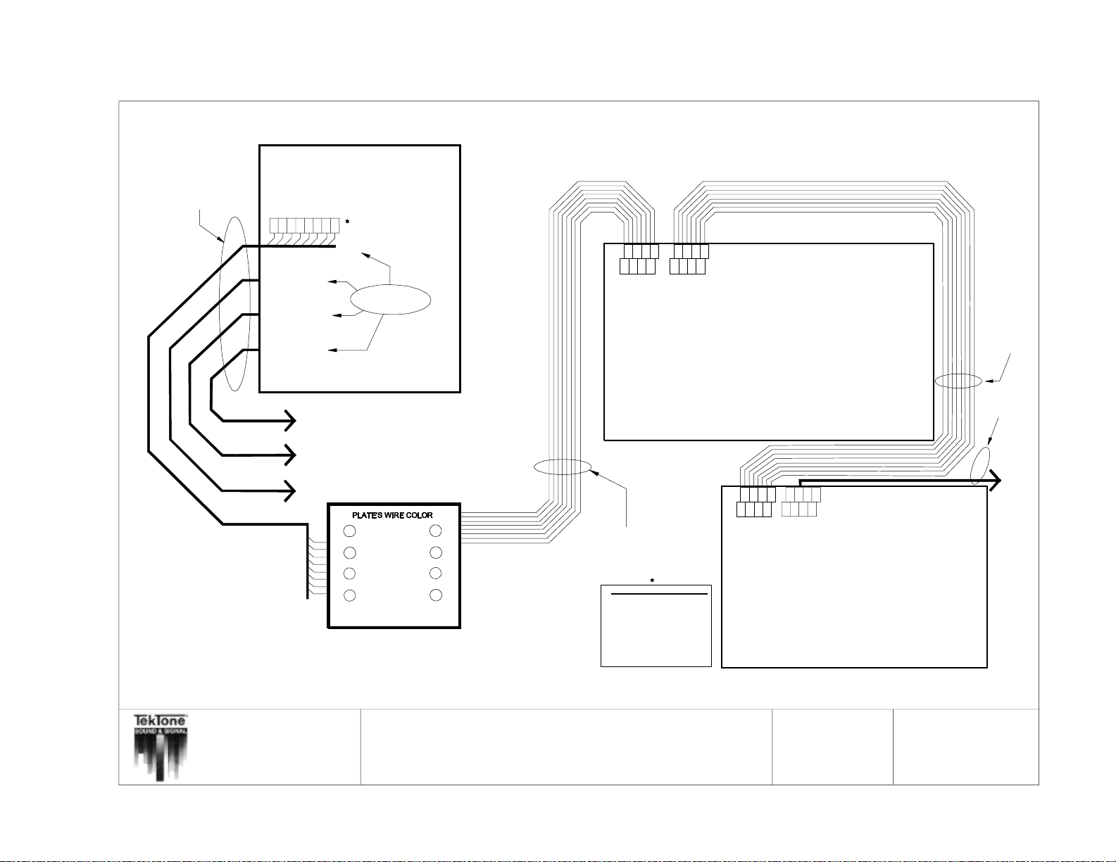
Copyright © TekTone Sound & Signal Mfg., Inc. All Rights Reserved.
4-#18 shielded and 4#18 per master station.
(See note below)
IL600 NC205 Tek-DIGICARE
To Master #1
NOTE:
1=+18VDC
2=CONTROL IN
3=POWER ON
4=CONTROL OUT
5=DIGITAL AUDIO IN
6=FAULT
7=DIGITAL AUDIO OUT
8=SYSTEM GROUND
®
Manual • 55
Pins 1 (+18VDC), 5 (Digital Audio IN),
7 (Digital Audio OUT), and 8 (System
Ground) are included in the shielded cable.
NOTE: All wire numbers are minimum AWG sizes.
All wire must be stranded.
Refer to NL205-H for maximum wiring distances and standard wire colors
NC260B Central Equipment
+18VDC
POWER ON
DIGITAL AUDIO IN
FAULT
SYSTEM GROUND
DIGITAL AUDIO OUT
8
MASTER #2
MASTER #3
MASTER #4
CONTROL IN
CONTROL OUT
67
12345
MASTER #1
8 wires each
To Master #4
To Master #3
To Master #2
BLUE
ORANGE
BLACK
1
2
3
45
8
WHITE
BROWN
7
6
YELLOW
GREEN RED
Wall Plate (TekTone® Part #PL467)
Observe wire and pin NAMES when connecting equipment !!!
*ALL FIELD WIRING MUST BE TERMINATED
OUSIDE OF SYSTEM EQUIPMENT ENCLOSURES*
54321
7
6
8
Master IN Expander OUT
1=+18VDC
2=CONTROL IN
3=POWER ON
4=CONTROL OUT
5=DIGITAL AUDIO IN
6=FAULT
7=DIGITAL AUDIO OUT
8=SYSTEM GROUND
8 conductor Modular cable (7' cable
provided each Master Station) with
each Master Station
PIN# STANDARD WIRE COLOR
BROWN
1
2
RED
ORANGE
3
4
YELLOW
5
GREEN
6
BLUE
VIOLET
7
8
GRAY
WHITE
9
10
BLACK
1
543
7
6
2
8
Modular jacks
NC250/230
MASTER STATION
234
1
Expander IN Expander OUT
54321
7
6
56788
Modular jacks
NOTE:
Addressing NC255 Master Expanders incorrectly
will result in damage to units upon power application.
Check Figure 9 for correct dipswitch settings.
NC255
MASTER EXPANDER
8 conductor
Modular cable
(1.3' cable provided
with each Master
Expander)
To other
Expanders
TITLE:
APP:
NC250/NC230 Master Stations &
NC255 Master Station Expander
NC205 Nurse Call System
DRAWN BY:
REV:
MJF
11
DATE:
PAGE:
6/4/2001
NL205-G
Page 66
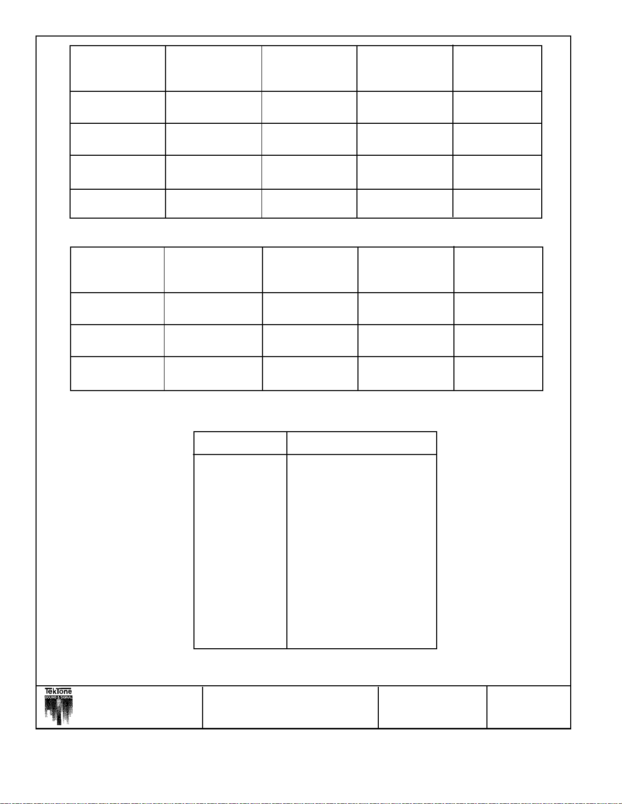
- Central Equipment
- CE Expanders
- Master Stations
- Master Expanders
NC260B NC262A NC250/230 NC255
NC260B X18´ TOTAL 250´ PER X
DISTANCE MASTER
NC262A 18´ TOTAL X X X
DISTANCE
NC250/230 250´ PER X X 10´ TOTAL
MASTER DISTANCE
NC255 XX10´ TOTAL 2´
DISTANCE
- Central Equipment
& Expanders
- IR & SF Series
Stations
- LI Series Lights
NC260B/262A X
IR Series X 100’ X
Stations
SF Series 100´ XX
Stations
NC260B/262A IR Series SF Series LI388A Zone
Stations Stations Light
1000´ TOTAL
(4 runs at 250´ per cable
run of 8 stations)
1000´ TOTAL
(4 runs at 250´ per cable
run of 8 stations)
500’ TOTAL
(stand alone)
500´ TOTAL
(stand alone)
(per expander)
1000´ TOTAL
(2 runs at 500´ per
cable run of 8 zone lights)
PIN # STANDARD WIRE COLOR
1 Brown
2 Red
3 Orange
4 Yellow
5 Green
6Blue
7 Violet (Purple)
8 Gray
9 White
10 Black
11 Brown/White
12 Red/White
13 Orange/White
14 Yellow/White
15 GreenWhite
®
TITLE: M aximum Wiring Distances DRAWN BY: MJF DATE: 09/18/2000
and Standard Wire Colors
APP: NC205 Nurse Call System REV: 8 PAGE: NL205-H
56 • IL600 NC205 Tek-DIGICARE® Manual
Copyright © TekTone Sound & Signal Mfg., Inc. All Rights Reserved.
Page 67
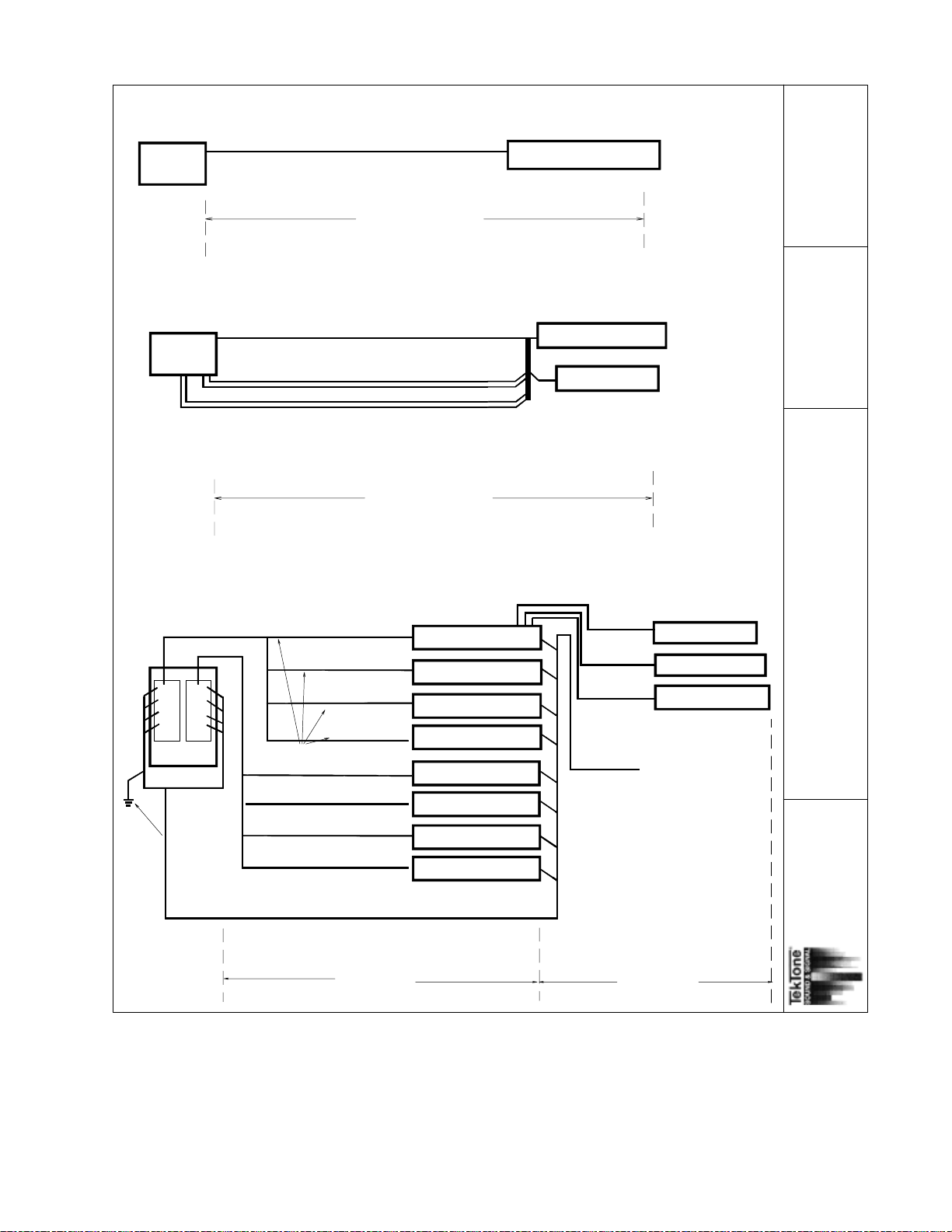
LI AND SF SERIES STATIONS FOR ZONE AND FLASHER BUS
NC260A
ZONE BUSS
18 awg stranded, up to 7 conductors
34pF/Ft., 5.9 ohms/1000' @ 25C maximum.
UP TO 16 LI388A STATIONS
with PK261A Dome Lamp Power Supply
NOTE: System limited to 8 duty devices, LI388A or IR260A
with dome lamps, in combination without PK261A.
2/2/9799
NL205-H-1
NC260A
chassis
ground
lug.
55pF/Ft., 14.7 ohms/1000' @ 25C maximum.
NC260A
NC260A
PM261
PM261
Selective cable trunk(s)
with selective ground
line grounded on one
end.
22 awg stranded
< 55pF/Ft.
<14.7 ohms/1000'
@ 25C.
Ref. NL205-E
18 awg stranded 5 conductor unshielded
with 18 awg shielded audio pair
UP TO 500'
1000' maximum per zone connection.
Eight dome lamps per run - maximum.
STAND-ALONE CONFIGURATION
22 awg stranded selective line
SF SERIES STATIONS
FAST FLASH
SLOW FLASH
FLASHER BUS
18 awg stranded
34pF/Ft., 5.9 ohms/1000' @ 25C maximum.
up to 6 conductor
SF STATIONS AND LI LIGHTS
MAY BE USED IN COMBINATION WITH
IR SERIES STATIONS FOR A TOTAL OF 250
IF STANDARD IR STATIONS ARE USED AND 128
IF ENHANCED IR ARE USED
UP TO 500'
NC205 CABLING CONFIGURATIONS
UP TO 8 IR SERIES STNS
UP TO 8 IR SERIES STNS
UP TO 8 IR SERIES STNS
COMMONS CABLE RUN
34pF/Ft., <5.9 ohms/1000' @ 25C - maximum.
68pF/Ft., <5.9 ohms/1000' @ 25C - maximum.
UP TO 8 IR SERIES STNS
UP TO 8 IR SERIES STNS
UP TO 8 IR SERIES STNS
UP TO 8 IR SERIES STNS
UP TO 8 IR SERIES STNS
LI SERIES LIGHTS
LI SERIES LIGHTS
SF SERIES STATIONS
EMERGENCY CONTACTS
18 awg or 22 awg
various cable configurations
Selective ground lines are left floating at end of run.
The other end is connected to the NC260A Chassis
Ground Lug.
PAGE:
DATE:
BMS
3
REV:
DRAWN BY:
and cable configuration
NC205 Nurse Call System
NC205 Maximum Wiring Distances
APP:
TITLE:
UP TO 250'
Copyright © TekTone Sound & Signal Mfg., Inc. All Rights Reserved.
UP TO 100'
IL600 NC205 Tek-DIGICARE® Manual • 57
Page 68
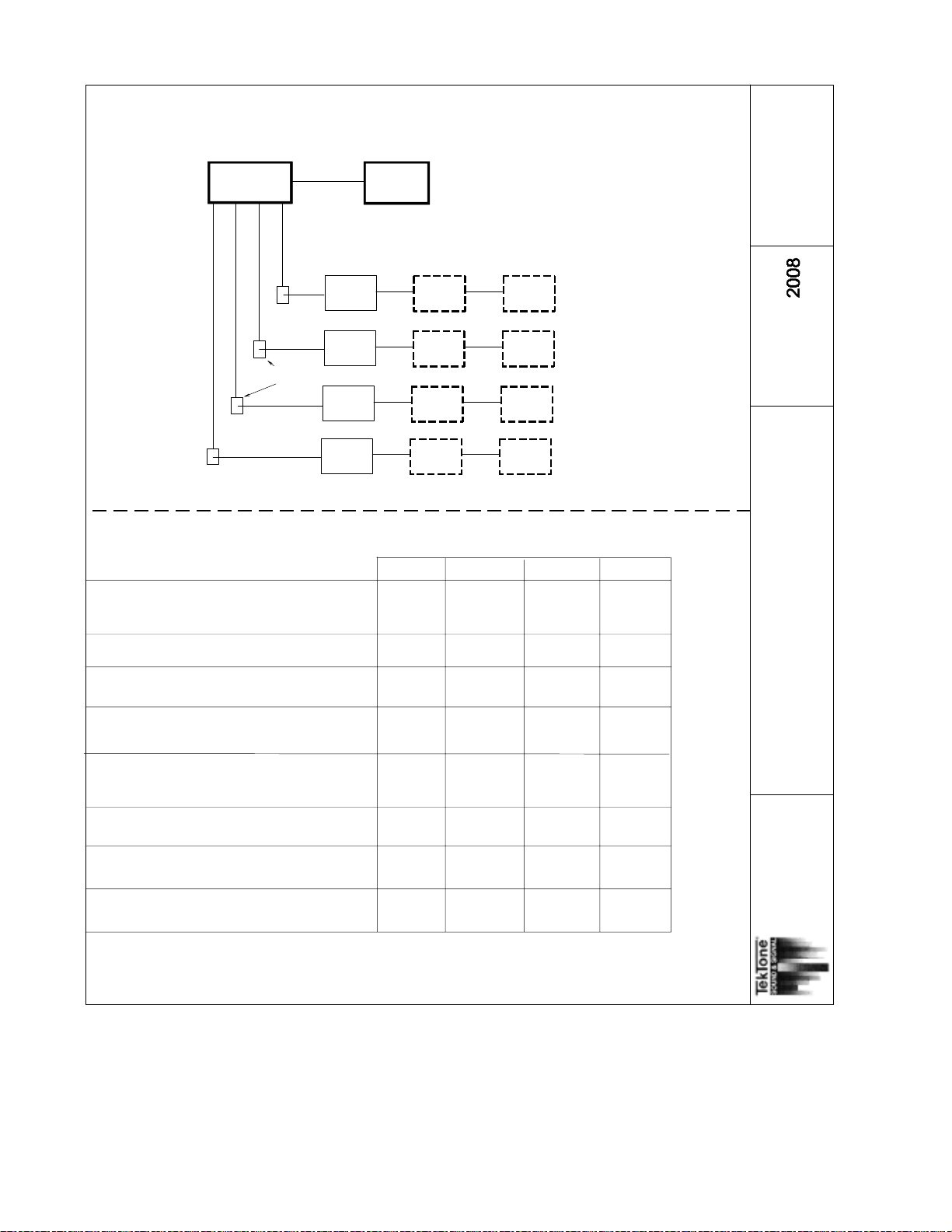
UP TO 250'
BETWEEN NC260B
AND JUNCTION BOX
18 awg stranded
4 conductor shielded
5.9 ohms/1000' @ 25C
34pf F/Ft. Maximum
plus
4 conductor unshielded
5.9 ohms/1000' @ 25C
68pf F/Ft. Maximum
Ref. NL205-G for details.
NC260B
JUNCTION BOX
CENTRAL EQUIPMENT CONNECTION
NC262
6'
STANDARD 25 CONDUCTOR SERIAL CABLE (STRAIGHT-THROUGH)
NC250/230
NC250/230
NC250/230
NC255/235
NC255/235
NC255/235
NC255/235
NC255/235
NC255/235
09/18/2000
NL205-H-2
PAGE:
DATE:
REP/MJF
4
Drawing #:
REV:
DRAWN BY:
NC250/230
7'
NC205 CENTRAL EQUIPMENT CONFIGURATION
UP TO 4 MASTER CONSOLES
UP TO 64 STANDARD IR OR SF STATIONS
WITH OR WITHOUT LI SERIES LIGHTS
PRINTER/PAGER INTERFACE CARD
64 TO 128 STANDARD IR OR SF STATIONS
WITH OR WITHOUT LI SERIES LIGHTS
UP TO 4 MASTER CONSOLES
UP TO 64 ENHANCED IR STATIONS
WITHOUT LI SERIES LIGHTS
UP TO 4 MASTER CONSOLES
UP TO 64 ENHANCED IR STATIONS
WITH LI SERIES LIGHTS
64 TO 128 ENHANCED IR STATIONS
WITHOUT LI SERIES LIGHTS
64 TO 128 ENHANCED IR STATIONS
WITH LI SERIES LIGHTS
LI388A OR IR260A
NC255/235
2'
8 CONDUCTOR MODULAR, RJ45 CONNECTORS
NC260B
NC262A
USE
USE
USE
USE
USE
USE
USE
N/A
NC255/235
2'
X
X
USE
X
X
USE
USE
N/A
NC261A
X
X
X
X
X
X
X
N/A
PK261A
X
X
X
X
USE
X
USE
USE
NC205 Central Equipment
Configurations and
Maximum Wiring Distances
NC205 NURSE CALL SYSTEM
TITLE:
APP:
58 • IL600 NC205 Tek-DIGICARE® Manual
Copyright © TekTone Sound & Signal Mfg., Inc. All Rights Reserved.
Page 69
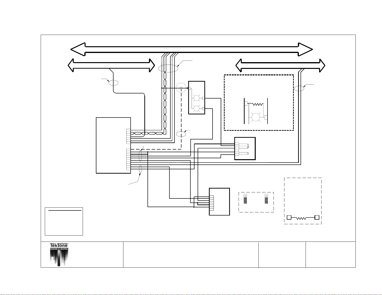
Copyright © TekTone Sound & Signal Mfg., Inc. All Rights Reserved.
SELECTIVE WIRE TRUNK FLASHER BUSS
#22
STATION COMMONS BUSS
twisted-shielded
pair for AUDIO )
OR
#18
( Includes one
DOME LIGHT
LI382
POWER
RED
WHITE
NOTE:
A 1.5K ohm resistor (TekTone pare # RC028, 1/2W, 5%)
must be installed across the POWER and RED lamp
terminals of the LI382 whenever smoke detector
or fire contacts are used with EMERGENCY stations.
1.5K ohm
POWER
#18
IL600 NC205 Tek-DIGICARE
PIN#
STANDARD WIRE COLOR
1
BROWN
2
RED
ORANGE
3
4
YELLOW
5
GREEN
6
BLUE
VIOLET
7
8
GRAY
WHITE
9
BLACK
®
Manual • 59
10
PATIENT STATION
IR250/251/252/253
STATION POWER
STATION GROUND
STATION GROUND
STATION GROUND
WHITE DOME
EMERGENCY
SLOW FLASH IN
FAST FLASH IN
SLOW FLASH OUT
FAST FLASH OUT
AUDIO (-)
AUDIO (+)
SELECT
NURSE
PRIORITY
POWER
FIRE
#22
1
2
3
4
5
6
7
#22
1
2
3
4
5
6
7
8
9
10
#18
EMERGENCY STATION
Observe wire and pin NAMES when connecting equipment!!!
NOTE: All wire numbers are minimum AWG sizes
All wire must be stranded.
TITLE:
IR250-IR253 Station Wiring
(includes SF Series Peripherals and LI Series Lights)
1
2
3
4
5
6
(SF337C only)
7
SF330
SF337C
SF340B
LI382
SMOKE DETECTOR
(UNSUPERVISED)
Auxillary Contacts
N.O.
N.C.
Alarm Contact
N.O.
SF337C only!
NOTE:
Both Jumpers on back of station
need to be in down position!
RED
DRAWN BY:
NOTE: If dome lamp is
not used, a 1.5K ohm
resistor (TekTone part
no. RC028, 1/2 watt,
5%) must be installed
from power on Patient
StationtoPin3on
Emergency Station
POWER EMERG.
13
MJF
STATION
DATE:
11/05/99
APP:
NC205 Nurse Call System
REV:
PAGE:
8
NL205-I
Page 70
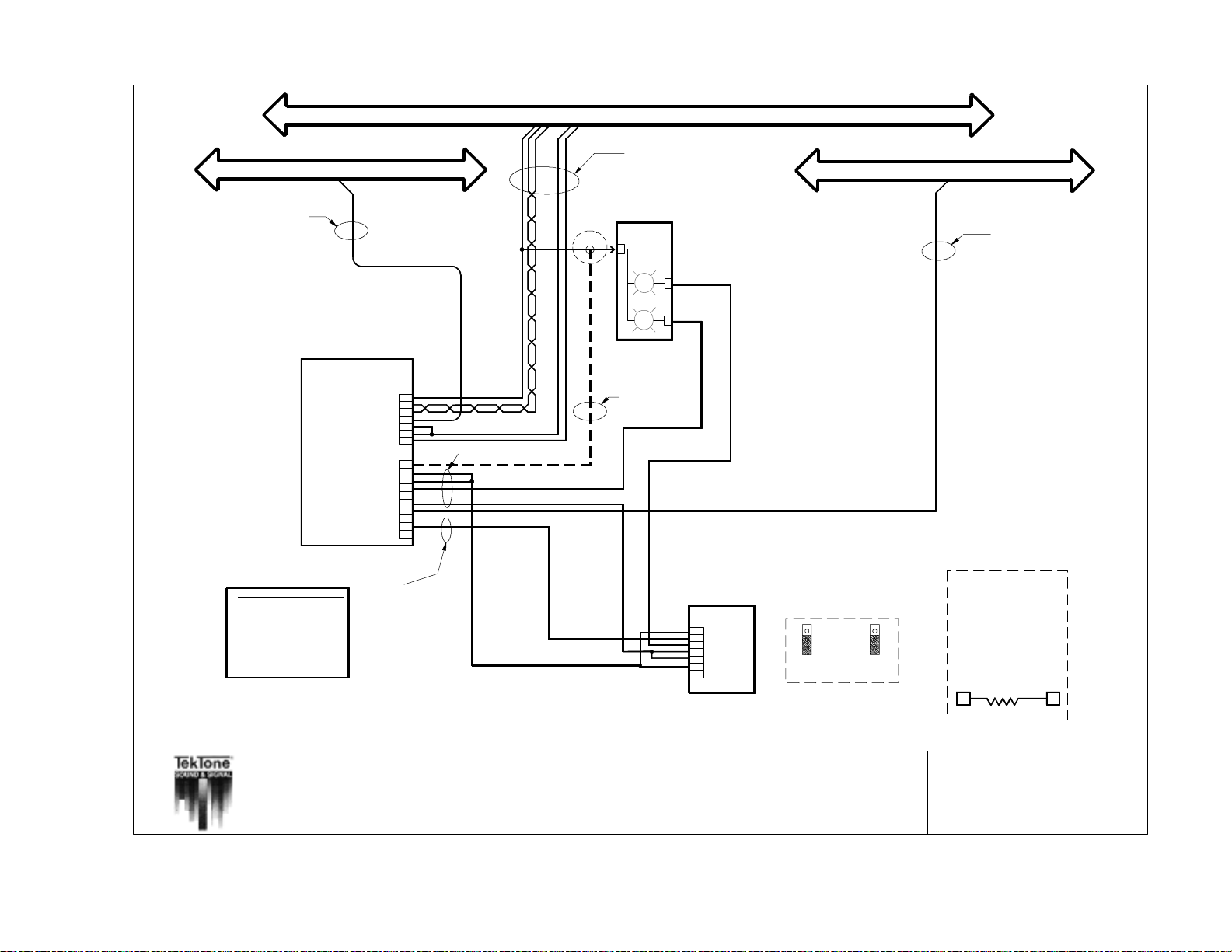
60 • IL600 NC205 Tek-DIGICARE
SELECTIVE WIRE TRUNK
STATION COMMONS BUSS
( Includes one
twisted-shielded
pair for AUDIO )
#18
FLASHER BUSS
®
Manual
Copyright © TekTone Sound & Signal Mfg., Inc. All Rights Reserved.
PIN# STANDARD WIRE COLOR
1
2
3
4
5
6
7
8
9
10
Observe wire and pin NAMES when connecting equipment!!!
NOTE: All wire numbers are minimum AWG sizes
All wire must be stranded.
BROWN
RED
ORANGE
YELLOW
GREEN
BLUE
VIOLET
GRAY
WHITE
BLACK
#22
PATIENT STATION
IR250/251/252/253
STATION GROUND
STATION GROUND
SLOW FLASH IN
FAST FLASH IN
SLOW FLASH OUT
FAST FLASH OUT
STATION POWER
AUDIO (-)
AUDIO (+)
SELECT
NURSE
PRIORITY
STATION GROUND
POWER
WHITE DOME
FIRE
EMERGENCY
#22
DOME LIGHT
OR
1
2
3
4
5
6
7
1
2
3
4
5
6
7
8
9
10
#22
POWER
WHITE
#18
LI382
RED
EMERGENCY STATION
1
2
3
4
5
6
7
SF330
SF337C
SF340B
(SF337C only)
SF337C only!
NOTE:
Both Jumpers on back of station
need to be in down position!
#18
NOTE: If dome lamp is
not used, a 1.5K ohm
resistor (TekTone part
no. RC028, 1/2 watt,
5%) must be installed
from power on Patient
Station to Pin 3 on
Emergency Station
POWER EMERG.
1
3
STATION
TITLE:
APP:
IR250-IR253 Standard Station Wiring
(reduced wiring scheme with Emergency Peripheral)
NC205 Nurse Call System
DRAWN BY:
REV:
NC
5
DATE:
PAGE:
12/15/98
NL205-J
Page 71
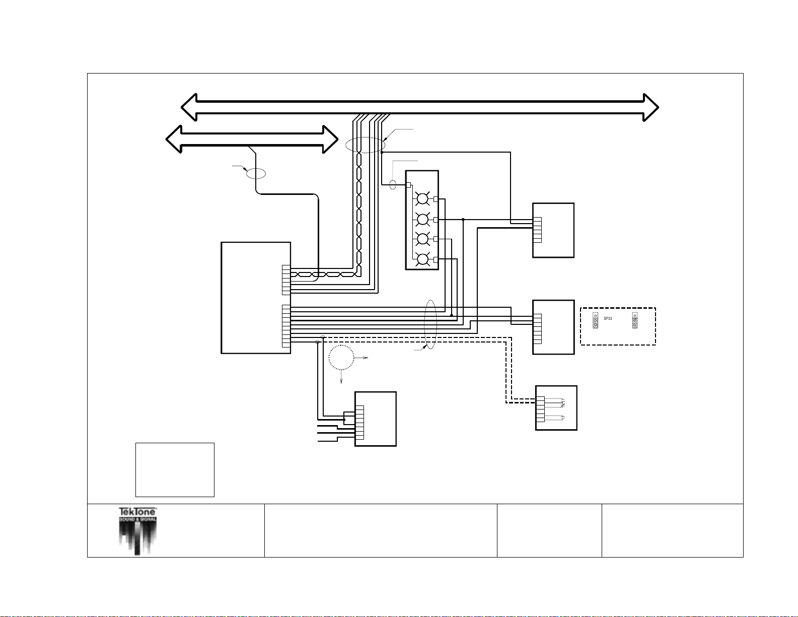
Copyright © TekTone Sound & Signal Mfg., Inc. All Rights Reserved.
SELECTIVE WIRE TRUNK
STATION COMMONS BUSS
( Includes one
twisted-shielded
pair for AUDIO )
#18
IL600 NC205 Tek-DIGICARE
PIN#
STANDARD WIRE COLOR
1
BROWN
2
RED
3
ORANGE
4
YELLOW
5
GREEN
6
BLUE
VIOLET
7
8
GRAY
9
WHITE
10
®
Manual • 61
BLACK
#22
PATIENT STATION
IR254/255/256
AUDIO(-)
AUDIO(+)
SELECT
NURSE
PRIORITY
POWER
BLUE DOME
RED DOME
WHITE DOME
GREEN DOME
EMERGENCY
CODE POWER
CODE INPUT
1
2
3
4
5
6
7
1
2
3
4
5
6
7
8
9
10
DOME LIGHT
#22
STATION POWER
STATION GROUND
NURSE PRESENCE
STATION GROUND
OR
To enable code fault reporting
the 2-pin CODE FAULT DISABLE
jumper must be removed from
the patient station.
Normally Open Contact
Common Contact
Normally Closed Contact
Observe all wire and pin NAMES when connecting equipment!!!
All wire numbers are minimum AWG sizes.
Refer to NL205-H for maximum wiring distances and standard wire colors.
NOTE: Fire indication at the nurse master station is supplementary only.
The NC205 system is not intended for use as a fire alarm evacuation system.
TITLE:
IR254-256 Enhanced Station Wiring
CODE CALL
STATION
SF341B
1
2
3
4
5
6
7
8
cannot be used simultaneously
on the same patient station.
All wire must be stranded.
(includes SF & LI Peripherals)
From Dome Power Buss
LI387
POWER
BLUE
GREEN
RED
WHITE
NOTE:
CODE CALL Stations and
SMOKE (FIRE) Contacts
STAFF PRESENCE
STATION
SF250
1
2
3
4
5
6
EMERGENCY STATION
SF330
SF337C
SF340B
1
2
3
4
5
6
7 (SF337C only)
SMOKE DETECTOR
(UNSUPERVISED)
Auxillary Contacts
Alarm Contact
DRAWN BY:
SF337C only!
NOTE: Both jumpers on back of station
need to be in down position!
The CODE FAULT DISABLE
2-pin jumper must be installed
on the patient station to use
N.O.
N.C.
a SMOKE (FIRE) peripheral.
N.O.
MJF/DE
DATE:
09/18/2000
APP:
NC205 Nurse Call System
REV:
5
PAGE:
NL205-K
Page 72
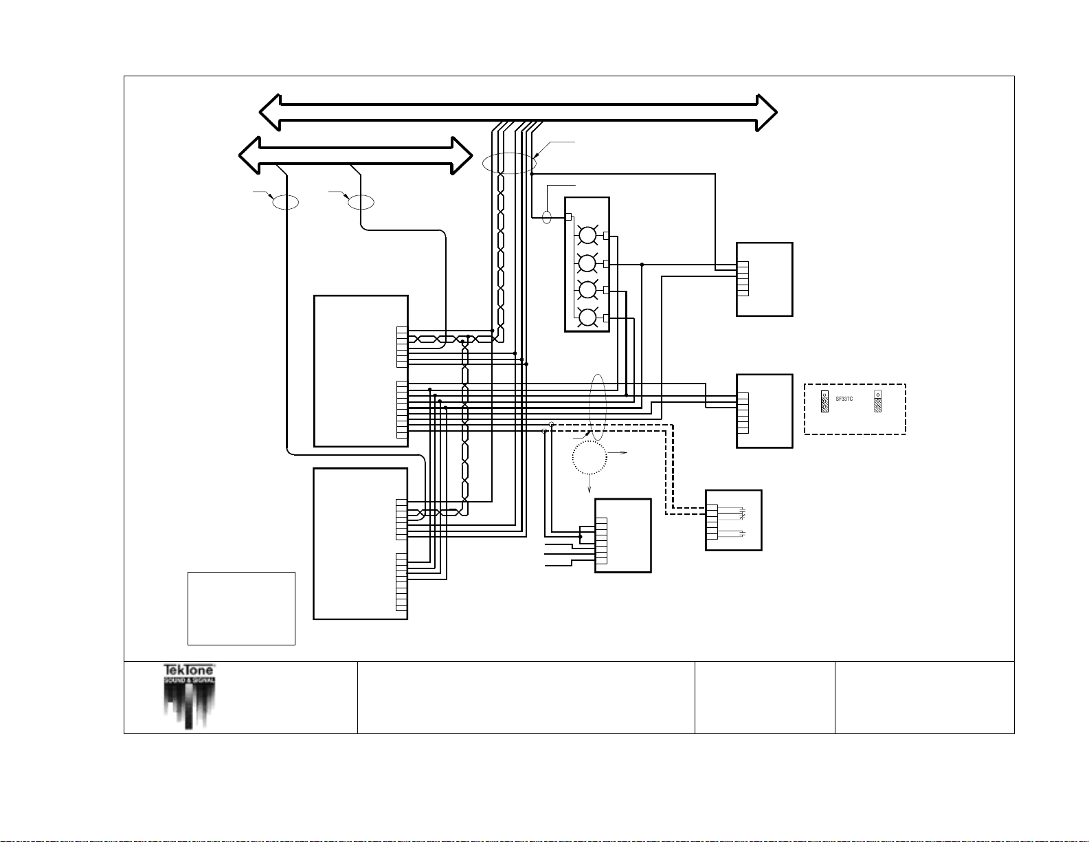
62 • IL600 NC205 Tek-DIGICARE
SELECTIVE WIRE TRUNK
STATION COMMONS BUSS
#18
( Includes one
twisted-shielded
pair for AUDIO )
®
Manual
Copyright © TekTone Sound & Signal Mfg., Inc. All Rights Reserved.
PIN#
STANDARD WIRE COLOR
BROWN
1
2
RED
3
ORANGE
4
YELLOW
5
GREEN
6
BLUE
VIOLET
7
GRAY
8
WHITE
9
BLACK
10
#22
#22
To enable code fault reporting
the 2-pin CODE FAULT DISABLE
jumper must be removed from
the patient station.
PATIENT STATION
IR254/255/256
AUDIO(-)
AUDIO(+)
SELECT
NURSE
PRIORITY
POWER
BLUE DOME
RED DOME
WHITE DOME
GREEN DOME
EMERGENCY
CODE INPUT
1
2
3
4
5
6
7
1
2
3
4
5
6
7
8
9
10
STATION POWER
STATION GROUND
NURSE PRESENCE
CODE POWER
STATION GROUND
PATIENT STATION
IR254/255/256
AUDIO(-)
AUDIO(+)
SELECT
NURSE
PRIORITY
POWER
BLUE DOME
RED DOME
EMERGENCY
CODE INPUT
1
2
3
4
5
6
7
1
2
3
4
5
6
7
8
9
10
STATION POWER
STATION GROUND
WHITE DOME
GREEN DOME
NURSE PRESENCE
CODE POWER
STATION GROUND
Normally Open Contact
Common Contact
Normally Closed Contact
From Dome Power Buss
LI387
POWER
BLUE
GREEN
RED
WHITE
DOME LIGHT
#22
OR
CODE CALL
STATION
SF341B
1
2
3
4
5
6
7
8
STAFF PRESENCE
STATION
SF250
1
2
3
4
5
6
EMERGENCY STATION
SF330
SF337B
SF337C
1
SF340B
2
3
4
5
6
7 (SF337C only)
SMOKE DETECTOR
(UNSUPERVISED)
Auxillary Contacts
Alarm Contact
NOTE: CODE CALL Stations and SMOKE (FIRE) Contacts
cannot be used simultaneously on the same patient station.
The CODE FAULT DISABLE
2-pin jumper must be installed
on the patient station to use
N.O.
N.C.
a SMOKE (FIRE) peripheral.
N.O.
SF337C only!
NOTE: Both jumpers on back of station
need to be in down position!
Observe all wire and pin NAMES when connecting equipment!!!
All wire numbers are minimum AWG sizes.
All wire must be stranded.
Refer to NL205-H for maximum wiring distances and standard wire colors.
NOTE: Fire indication at the nurse master station is supplementary only.
The NC205 system is not intended for use as a fire alarm evacuation system.
TITLE:
APP:
IR254-256 Enhanced Station Wiring in Multiples
(includes SF & LI Peripherals)
NC205 Nurse Call System
DRAWN BY:
REV:
5
MJF/DE
DATE:
PAGE:
09/18/2000
NL205-L
Page 73
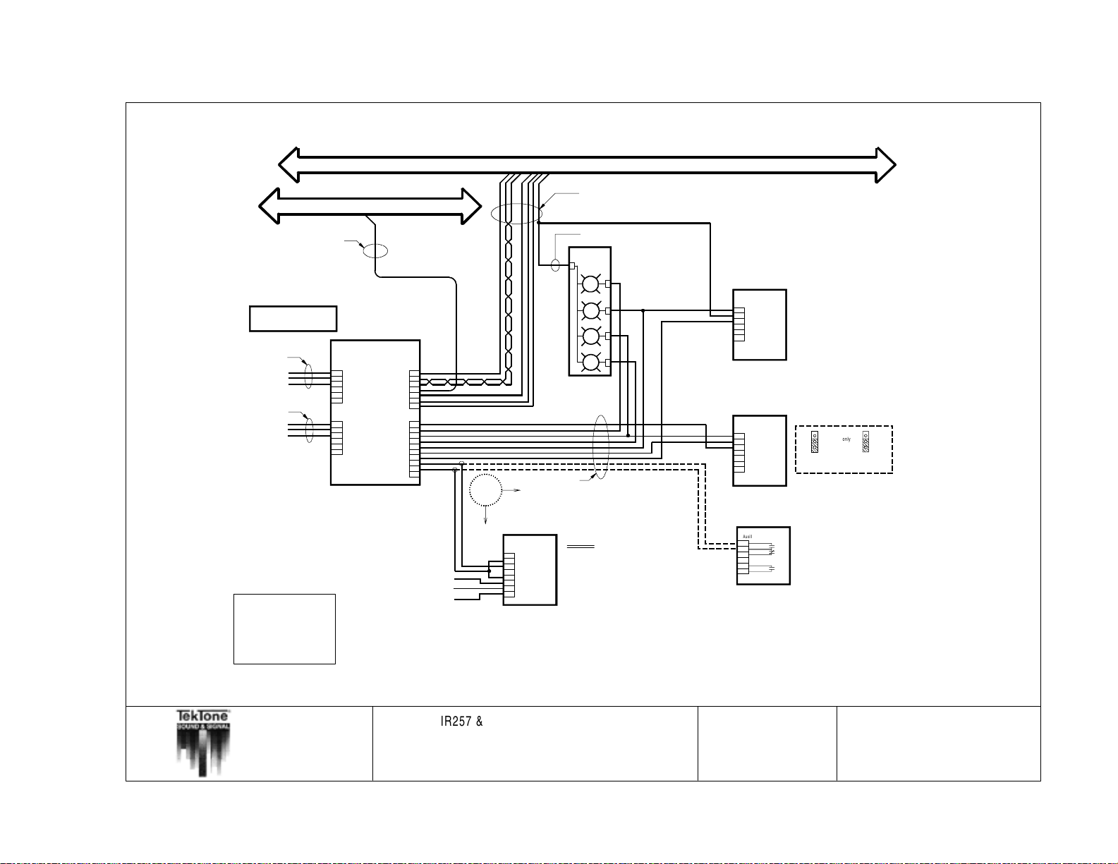
Copyright © TekTone Sound & Signal Mfg., Inc. All Rights Reserved.
External Connections
from Hospital Grade TV
UL 1410 Listed
TV COMMON
TV AUDIO
TV SWITCH
TV COMMON
TV AUDIO
TV SWITCH
TV2 available on IR258 only
IL600 NC205 Tek-DIGICARE
PIN#
STANDARD WIRE COLOR
1
2
3
4
5
6
7
8
9
®
Manual • 63
10
SELECTIVE WIRE TRUNK
SELECTIVE WIRE TRUNK
#22
#22
External Connections
from Hospital Grade TV
UL 1410 Listed
#22
#22
TV COMMON
TV AUDIO
TV SWITCH
#22
TV COMMON
#22
TV AUDIO
TV SWITCH
TV2 available on IR258 only
To enable code fault reporting
the 2-pin CODE FAULT DISABLE
jumper must be removed from
PATIENT STATION
PATIENT STATION
1
2
1
TV1
3
2
4
3
5
4
6
5
6
STATION GROUND
1
2
3
1
TV2
4
2
5
3
6
4
5
6
To enable code fault reporting
the 2-pin CODE FAULT DISABLE
jumper must be removed from
the patient station.
the patient station.
PIN# STANDARD WIRE COLOR
1
BROWN
2
RED
3
ORANGE
4
YELLOW
5
GREEN
BROWN
6
BLUE
RED
VIOLET
7
ORANGE
8
YELLOW
9
GREEN
10
BLUE
VIOLET
GRAY
WHITE
BLACK
GRAY
WHITE
BLACK
Observe all wire and pin NAMES when connecting equipment!!!
All wire numbers are minimum AWG sizes.
Refer to NL205-H for maximum wiring distances and standard wire colors.
NOTE: Fire indication at the nurse master station is supplementary only.
The NC205 system is not intended for use as a fire alarm evacuation system.
STATION COMMONS BUSS
STATION COMMONS BUSS
IR257/258
IR257/258
AUDIO ( - )
1
AUDIO ( + )
2
SELECT
3
NURSE
4
PRIORITY
NURSE
5
6
7
POWER
BLUE DOME
RED DOME
POWER
1
WHITE DOME
2
GREEN DOME
3
EMERGENCY
4
5
CODE POWER
6
CODE INPUT
7
8
9
10
1
2
3
4
5
6
7
1
2
3
4
5
6
7
8
9
10
OR
STATION POWER
TV1
STATION POWER
AUDIO(-)
AUDIO(+)
SELECT
STATION GROUND
PRIORITY
TV2
BLUE DOME
RED DOME
WHITE DOME
NURSE PRESENCE
GREEN DOME
EMERGENCY
NURSE PRESENCE
STATION GROUND
CODE POWER
CODE INPUT
STATION GROUND
OR
CODE CALL
STATION
SF341B
CODE CALL
STATION
1
2
SF341B
3
4
1
Normally Open Contact
Common Contact
Normally Closed Contact
Normally Open Contact
Observe all wire and pin NAMES when connecting equipment!!!
All wire numbers are minimum AWG sizes.
Refer to NL205-H for maximum wiring distances and standard wire colors.
Common Contact
Normally Closed Contact
NOTE: Fire indication at the nurse master station is supplementary only.
The NC205 system is not intended for use as a fire alarm evacuation system.
TITLE:
IR257 & IR258 Enhanced Station Wiring
5
2
6
7
3
8
4
5
6
7
8
All wire must be stranded.
All wire must be stranded.
#18
#18
( Includes one
( Includes one
twisted-shielded
twisted-shielded
pair for AUDIO )
pair for AUDIO )
From Dome Power Buss
From Dome Power Buss
LI387
LI387
POWER
POWER
BLUE
BLUE
GREEN
GREEN
RED
RED
WHITE
WHITE
DOME LIGHT
DOME LIGHT
#22
#22
cannot be used simultaneously
NOTE:
CODE CALL Stations and
NOTE:
SMOKE (FIRE) Contacts
CODE CALL Stations and
cannot be used simultaneously
SMOKE (FIRE) Contacts
on the same patient station.
on the same patient station.
STAFF PRESENCE
STAFF PRESENCE
STATION
STATION
SF250
SF250
1
1
2
2
3
3
4
4
5
5
6
6
EMERGENCY STATION
EMERGENCY STATION
SF330
SF337B
SF337C
SF330
SF340B
1
SF337B
2
SF337C
3
SF340B
1
4
2
5
3
6
4
7 (SF337C only)
5
6
(SF337C only)
7
SMOKE DETECTOR
(UNSUPERVISED)
SMOKE DETECTOR
Auxillary Contacts
(UNSUPERVISED)
N.O.
N.C.
Auxillary Contacts
Alarm Contact
N.O.
Alarm Contact
DRAWN BY:
SF337C only!
NOTE: Both jumpers on back of station
SF337C only!
need to be in down position!
NOTE: Both jumpers on back of station
need to be in down position!
The CODE FAULT DISABLE
2-pin jumper must be installed
The CODE FAULT DISABLE
on the patient station to use
2-pin jumper must be installed
a SMOKE (FIRE) peripheral.
on the patient station to use
N.O.
N.C.
a SMOKE (FIRE) peripheral.
N.O.
MJF/DE
DATE:
09/18/2000
APP:
NC205 Nurse Call System
REV:
5
PAGE:
NL205-M
Page 74
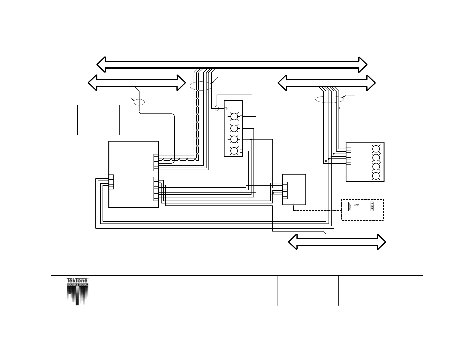
64 • IL600 NC205 Tek-DIGICARE
PIN#
STANDARD WIRE COLOR
1
BROWN
2
RED
3
ORANGE
4
YELLOW
5
GREEN
6
BLUE
VIOLET
®
Manual
Copyright © TekTone Sound & Signal Mfg., Inc. All Rights Reserved.
7
GRAY
8
WHITE
9
10
BLACK
SELECTIVE WIRE TRUNK
#22
DUTY STATION
IR260A
STATION POWER
AUDIO(-)
AUDIO(+)
PRIORITY
STATION GROUND
1
ZONE DATA 0
2
ZONE DATA 1
3
ZONE DATA 2
4
ZONE SELECT
5
6
STATION GROUND
STATION GROUND
EMERGENCY
SLOW FLASH IN
SLOW FLASH OUT
WHITE DOME
BLUE DOME
RED DOME
GREEN DOME
SELECT
NURSE
POWER
N/A
STATION COMMONS BUSS
#18
( Includes one
twisted-shielded
pair for AUDIO )
From Dome Power Buss
LI387
POWER
BLUE
GREEN
RED
WHITE
1
2
3
4
5
6
7
1
2
3
4
5
6
7
8
9
10
DOME LIGHT
NOTE:
NC205 system is limited to 8 duty devices if
PK261A Dome Lamp Power Supply is not used.
These duty devices may be LI388A or IR260A
with dome lamps, in any combination, but
cannot exceed 8 maximum. Reference NL205-E
for alternate dome power connection.
EMERGENCY STATION
1
2
3
4
5
6
(SF337C only)
7
SF330
SF337C
SF340B
ZONE BUSS
#18
From Dome Power Buss
ZONE LIGHT
LI388A
1
DOME POWER
2
ZONE POWER
3
ZONE DATA 0
4
ZONE DATA 1
5
ZONE DATA 2
6
ZONE SELECT
7
SYSTEM GROUND
SF337C only!
NOTE: Both jumpers on back of station
need to be in down position!
Observe all wire and pin NAMES when connecting equipment!!!
All wire numbers are minimum AWG sizes.
All wire should be stranded.
Refer to NL205-H for maximum wiring distances and standard wire colors.
TITLE:
APP:
IR260A & LI388A Wiring
NC205 Nurse Call System
DRAWN BY:
REV:
5
FLASHER BUSS
MJF/DE
DATE:
PAGE:
12/07/98
NL205-N
Page 75
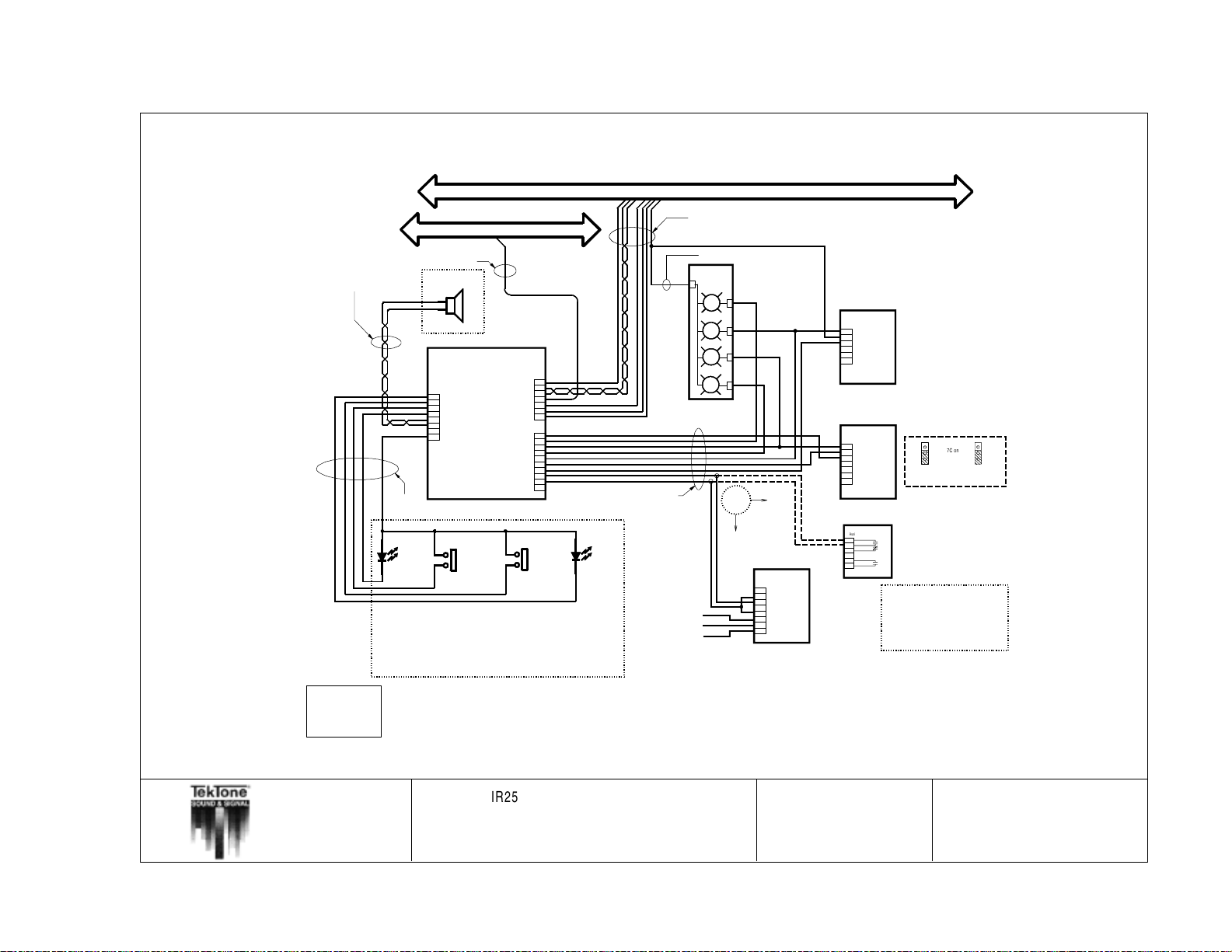
Copyright © TekTone Sound & Signal Mfg., Inc. All Rights Reserved.
IL600 NC205 Tek-DIGICARE
PIN# STANDARD WIRE COLOR
1
2
3
4
5
6
7
8
9
®
Manual • 65
10
#18
twisted-shielded
PIN# STANDARD WIRE COLOR
BROWN
RED
ORANGE
YELLOW
GREEN
BLUE
VIOLET
GRAY
WHITE
BLACK
10
STATION COMMONS BUSS
SELECTIVE WIRE TRUNK
#22
SELECTIVE WIRE TRUNK
SPEAKER
+
#18
twisted-shielded
-
MULTI-PURPOSE STATION
1
CALL LED
2
CALL BUTTON
RESET BUTTON
3
IN-USE LED
4
5
AUDIO(-)
AUDIO(+)
6
7
STATION POWER
8
#22
#22
RESET BUTTON
IN-USE LED
IN-USE LED
RECOMMENDATIONS :
SPEAKER
CALL LED
IN-USE LED
CALL BUTTON
Observe all wire and pin NAMES when connecting equipment!!!
1
2
3
4
5
6
7
8
9
RESET BUTTON
BROWN
RED
ORANGE
YELLOW
GREEN
Observe all wire and pin NAMES when connecting equipment!!!
BLUE
VIOLET
GRAY
All wire numbers are minimum AWG sizes.
WHITE
BLACK
Refer to NL205-H for maximum wiring distances and standard wire colors.
All wire numbers are minimum AWG sizes.
Refer to NL205-H for maximum wiring distances and standard wire colors.
NOTE: Fire indication at the nurse master station is supplementary only.
The NC205 system is not intended for use as a fire alarm evacuation system.
#22
SPEAKER
+
-
IR259
MULTI-PURPOSE STATION
1
2
3
4
5
6
7
8
STATION POWER
AUDIO(-)
AUDIO(+)
SELECT
NURSE
PRIORITY
CALL LED
CALL BUTTON
STATION GROUND
RESET BUTTON
IN-USE LED
AUDIO(-)
POWER
AUDIO ( + )
BLUE DOME
STATION POWER
RED DOME
WHITE DOME
GREEN DOME
EMERGENCY
NURSE PRESENCE
CODE POWER
CODE INPUT
STATION GROUND
RESET BUTTON
CALL BUTTON
IR259
1
2
3
STATION POWER
4
AUDIO(-)
5
AUDIO ( + )
6
7
PRIORITY
STATION GROUND
1
2
3
BLUE DOME
4
RED DOME
5
WHITE DOME
6
GREEN DOME
7
EMERGENCY
NURSE PRESENCE
8
CODE POWER
9
CODE INPUT
10
STATION GROUND
SELECT
NURSE
POWER
CALL BUTTON
RECOMMENDATIONS :
SPEAKER
CALL LED
: 60 ohm nominal impedance
IN-USE LED
: Standard Yellow ( Vf ~ 2.0 )
CALL BUTTON
: Standard Red ( Vf ~ 2.0 )
RESET BUTTON
: SPST momentary contact
: 60 ohm nominal impedance
: Standard Yellow ( Vf ~ 2.0 )
: Standard Red ( Vf ~ 2.0 )
: SPST momentary contact
: SPST momentary contact
: SPST momentary contact
1
2
3
4
5
6
7
1
2
3
4
5
6
7
8
9
10
CALL LED
STATION COMMONS BUSS
#22
CALL LED
Normally Open Contact
Normally Closed Contact
Common Contact
Normally Closed Contact
All wire must be stranded.
All wire must be stranded.
NOTE: Fire indication at the nurse master station is supplementary only.
The NC205 system is not intended for use as a fire alarm evacuation system.
TITLE:
IR259 Enhanced Station Wiring
#18
( Includes one
twisted-shielded
pair for AUDIO )
( Includes one
From Dome Power Buss
twisted-shielded
pair for AUDIO )
LI387
POWER
From Dome Power Buss
BLUE
GREEN
RED
WHITE
DOME LIGHT
DOME LIGHT
#22
Normally Open Contact
Common Contact
#18
LI387
POWER
BLUE
GREEN
RED
WHITE
OR
OR
CODE CALL
CODE CALL
STATION
STATION
SF341B
SF341B
1
2
1
3
2
4
5
3
6
4
7
5
8
6
7
8
To enable code fault reporting
the 2-pin CODE FAULT DISABLE
To enable code fault reporting
jumper must be removed from
the 2-pin CODE FAULT DISABLE
the patient station.
jumper must be removed from
the patient station.
DRAWN BY:
STAFF PRESENCE
STATION
SF250
STAFF PRESENCE
1
STATION
2
SF250
3
4
1
5
2
6
3
4
5
6
EMERGENCY STATION
EMERGENCY STATION
SF330
SF337B
SF330
SF337C
SF337B
1
SF340B
SF337C
2
1
SF340B
3
2
4
3
5
4
6
5
6
7 (SF337C only)
(SF337C only)
7
SMOKE DETECTOR
SMOKE DETECTOR
(UNSUPERVISED)
(UNSUPERVISED)
Auxillary Contacts
Auxillary Contacts
Alarm Contact
Alarm Contact
NOTE: Both jumpers on back of station
NOTE: Both jumpers on back of station
need to be in down position!
The CODE FAULT DISABLE
2-pin jumper must be installed
2-pin jumper must be installed
N.O.
N.O.
N.C.
on the patient station to use
N.C.
a SMOKE (FIRE) peripheral.
N.O.
N.O.
CODE CALL Stations and
SMOKE (FIRE) Contacts
CODE CALL Stations and
cannot be used simultaneously
SMOKE (FIRE) Contacts
on the same patient station.
cannot be used simultaneously
on the same patient station.
MJF/DE
SF337C only!
SF337C only!
need to be in down position!
The CODE FAULT DISABLE
on the patient station to use
a SMOKE (FIRE) peripheral.
NOTE:
NOTE:
09/18/2000
DATE:
APP:
NC205 Nurse Call System
REV:
5
PAGE:
NL205-O
Page 76
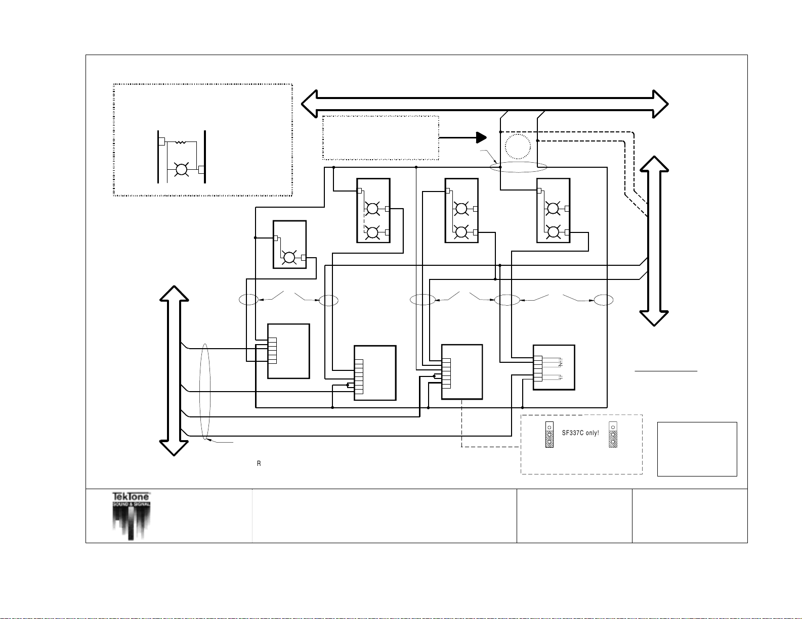
66 • IL600 NC205 Tek-DIGICARE
A
1
.5
K
o
h
m
re
s
rm
in
a
ls
POWER
is
o
f
th
must be installed across the POWER and BLUE lamp
te
Code Call station is used as a Stand-Alone station.
®
Manual
Copyright © TekTone Sound & Signal Mfg., Inc. All Rights Reserved.
NOTE :
to
r
(T
e
e
L
I3
1.5K ohm
LI387
k
T
o
n
e
p
a
rt
#
R
C
0
2
8
,
1
/2
W
,
5
%
)
8
7
w
h
e
n
a
n
S
F
3
4
1
BLUE
B
System Ground and Power for
stand-alone devices can be run
from the STATION COMMONS BUSS
DOME LIGHT
LI381
POWER
WHITE
NOTE :
or from the FLASHER BUSS.
DOME LIGHT
LI387
POWER
BLUE
WHITE
STATION COMMONS BUSS
#18
POW ER SYSTEM GROUND
DOME LIGHT
LI382
POWER
WHITE
RED
OR
DOME LIGHT
LI382
POWER
WHITE
RED
FLASHER BUSS
FAST FLASH
SLOW FLASH
#18
VISUAL-ONLY
STATION
SF100C
SF101C
1
2
3
4
5
6
CODE CALL
STATION
(UNSUPERVISED)
SF341B
1
2
3
4
5
6
7
8
#18
#18
EMERGENCY STATION SMOKE DETECTOR
1
2
3
4
5
6
(SF337C only)
7
SF330
SF337B
SF337C
SF340B
Auxillary Contacts
Alarm Contact
N.O.
N.C.
N.O.
IMPORTANT NOTE :
Stand-Alone stations must be marked
for FAULT DEFEAT and PRIVACY
at the associated master station.
SELECTIVE WIRE TRUNK
#22
Observe all wire and pin NAMES when connecting equipment!!!
All wire numbers are minimum AWG sizes.
Refer to NL205-H for maximum wiring distances and standard wire colors.
NOTE: Fire indication at the nurse master station is supplementary only.
The NC205 system is not intended for use as a fire alarm evacuation system.
TITLE:
Stand Alone use of SF Series Peripherals
All wire must be stranded.
(includes fire or smoke contacts)
APP:
NC205 Nurse Call System
SF337C only!
NOTE: Both jumpers on back of station
need to be in down position!
DRAWN BY:
REV:
MJF/DE
10
PIN# STANDARD WIRE COLOR
1
2
3
4
5
6
7
8
9
10
DATE:
11/3/1999
PAGE:
BROWN
RED
ORANGE
YELLOW
GREEN
BLUE
VIOLET
GRAY
WHITE
BLACK
NL205-P
Page 77
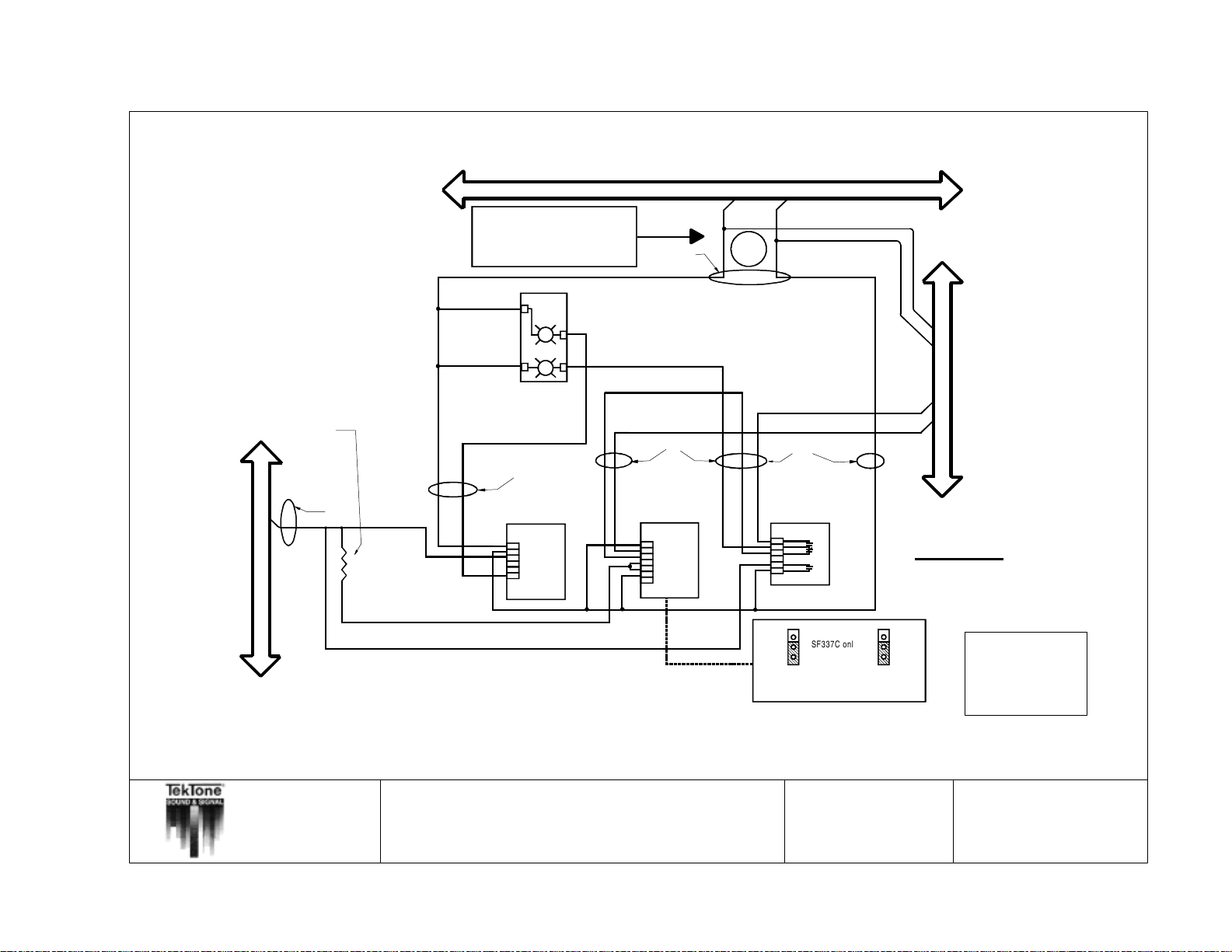
Copyright © TekTone Sound & Signal Mfg., Inc. All Rights Reserved.
STATION COMMONS BUSS
NOTE :
System Ground and Power for
stand-alone devices can be run
from the STATION COMMONS BUSS
or from the FLASHER BUSS.
DOME LIGHT
LI387
POWER
WHITE
RED
#18
OR
POWER SYSTEM GROUND
FLASHER BUSS
4.7K 1/2 Watt Tektone part # RC034
IL600 NC205 Tek-DIGICARE
®
Manual • 67
SELECTIVE WIRE TRUNK
#22
#18
#18
VISUAL-ONLY
STATION
SF100C
SF101C
1
2
3
4
5
6
Observe all wire and pin NAMES when connecting equipment!!!
All wire numbers are minimum AWG sizes.
Refer to NL205-H for maximum wiring distances and standard wire colors.
NOTE: Fire indication at the nurse master station is supplementary only.
The NC205 system is not intended for use as a fire alarm evacuation system.
TITLE:
Visual Station With Peripherals
All wire must be stranded.
EMERGENCY STATION SMOKE DETECTOR
SF330
SF337B
SF337C
1
SF340B
2
3
4
5
6
(SF337C only)
7
(includes emergency station and smoke contacts)
APP:
NC205 Nurse Call System
FAST FLASH
SLOW FLASH
#18
Auxillary Contacts
N.O.
N.C.
Alarm Contact
N.O.
Stand-Alone stations must be marked
for FAULT DEFEAT and PRIVACY
at the associated master station.
SF337C only!
NOTE: Both jumpers on back of station
need to be in down position!
DRAWN BY:
REV:
CGB/DE
4
IMPORTANT NOTE :
PIN# STANDARD WIRE COLOR
1
2
3
4
5
6
7
8
9
10
DATE:
PAGE:
BROWN
RED
ORANGE
YELLOW
GREEN
BLUE
VIOLET
GRAY
WHITE
BLACK
11/4/1999
NL205-P-1
Page 78
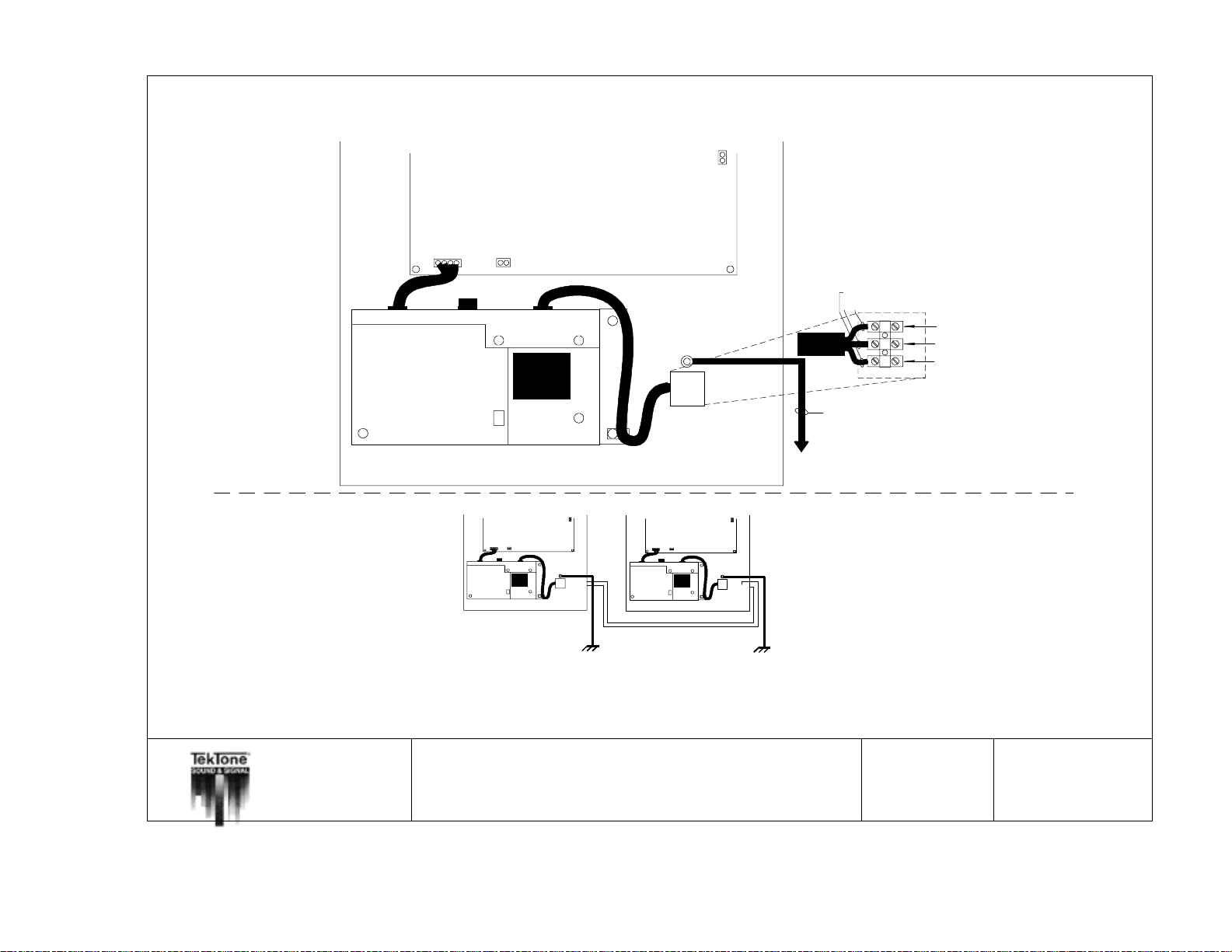
68 • IL600 NC205 Tek-DIGICARE
®
Manual
NC260B Cabinet
Ground Lug
110 VAC
Terminal Block
NOTE: This power input
must be connected so
that the NC260B & the
PK261A receive power at
the same time.
Green
Brown
Blue
#14 Gauge
Connect to good Earth Ground
Line
Neutral
Ground
Copyright © TekTone Sound & Signal Mfg., Inc. All Rights Reserved.
Single Point Ground
Methodology
TITLE: DRAWN BY:
APP:
NC260B
Cabinet
GroundLug
Good Earth Ground
110VAC
TerminalBlock
NC262A
Cabinet
GroundLug
110VAC
TerminalBlock
Good Earth Ground
NC260B/2A 120 VAC Connection Diagram
NC205 Nurse Call System
REV:
MJF
9
DATE:
PAGE:
11/3/1999
NL205-Q
Page 79
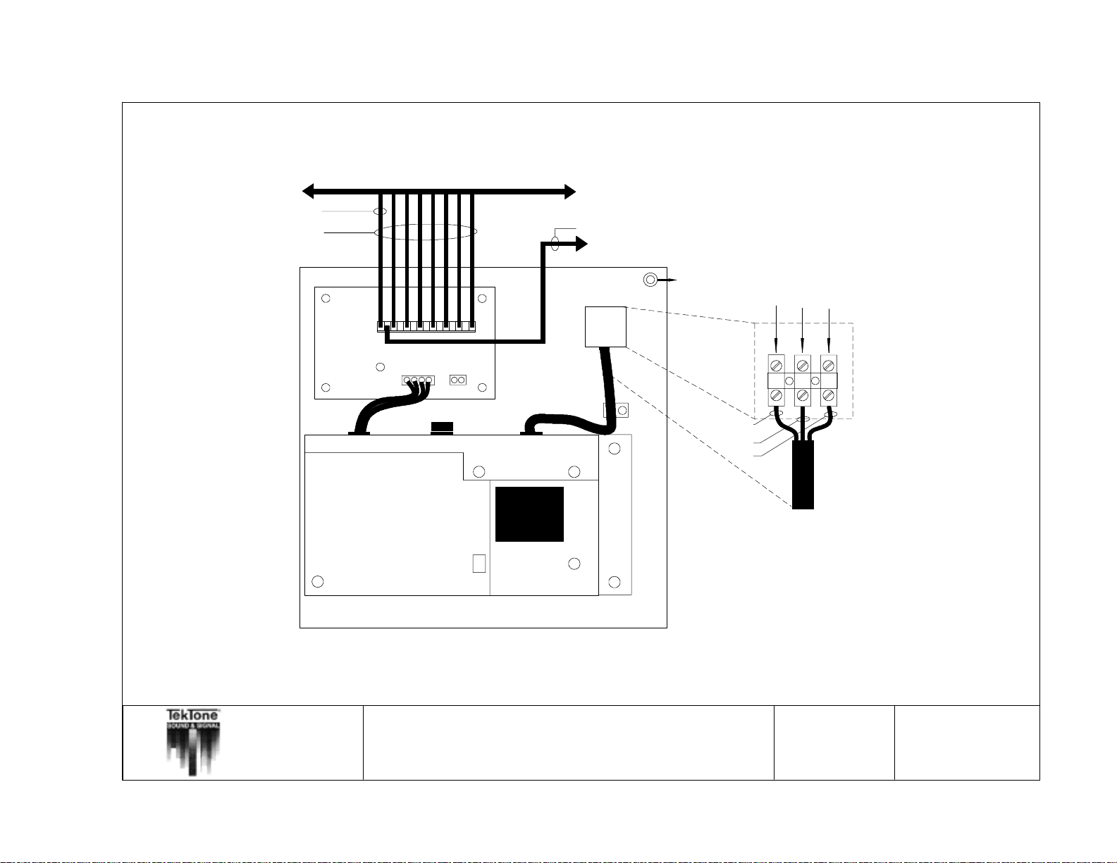
Copyright © TekTone Sound & Signal Mfg., Inc. All Rights Reserved.
16 Dome Lamps Maximum
IL600 NC205 Tek-DIGICARE
Red
Dome Power Buss
Power
LED
Black
To System Power Common in NC260B
To NC260B Chassis
Ground Lug
110 VAC
Terminal Block
Ground Lug or good
Earth Ground
Blue
Brown
Green
Line
Neutral
Ground
®
Manual • 69
TITLE:
APP:
PK261A Wiring Diagram
NC205 Nurse Call System
NOTE: This power input must be connected
so that the NC260B and the PK261A receive power
at the same time.
DRAWN BY:
REV:
MJF
6
DATE:
PAGE:
11/4/1999
NL205-R
Page 80
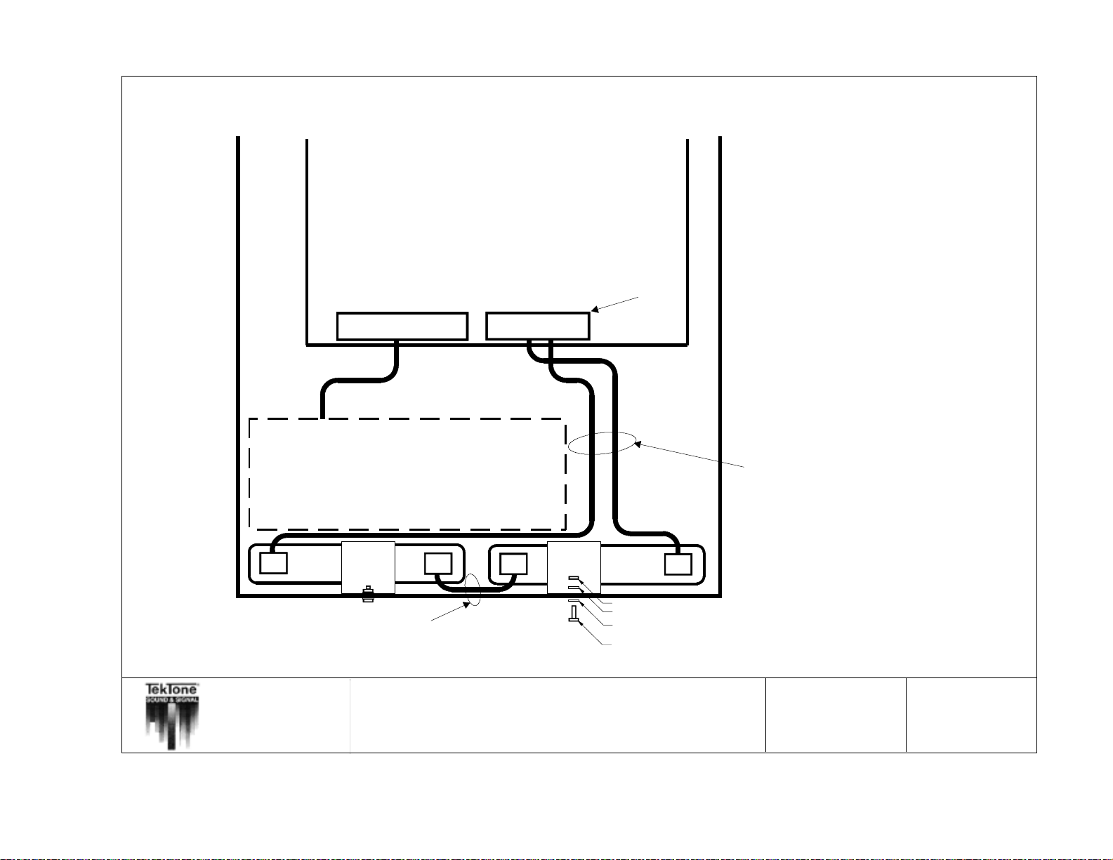
70 • IL600 NC205 Tek-DIGICARE
®
Manual
NC260B Central Equipment
or NC262A Central Expander
PM260B Motherboard
SYSTEM
POWER
4 pin Header
BACKUP
BATTERY
2 pin Header
Interconnect Plug
REDBLACK
Installation of the BA002K:
1. Place batteries (Tektone part number BA001) into
bottom of IH260 chassis as indicated in diagram.
2. Mount included support brackets (Tektone part
number CL135) to IH260 using included hardware.
3. Connect battery wiring harness as indicated in
diagram.
4. Plug battery wiring harness interconnect plug into
receptacle provided on motherboard (Tektone part
number PM260B) with system power on.
Replacement of the BA002K:
1. Remove battery interconnect plug from motherboard
receptacle.
2. Remove battery wiring harness.
3. Remove battery support brackets.
4. Remove old batteries from system housing and
replace with new batteries (12 VDC 1.9AH - 2.0AH).
5. Reinstall battery support brackets.
6. Connect battery wiring harness as indicated in
diagram.
7. Plug battery wiring harness interconnect plug into
receptacle provided on motherboard with
system power on.
Copyright © TekTone Sound & Signal Mfg., Inc. All Rights Reserved.
NOTE: All wire numbers are minimum AWG sizes.
PK260 Power Supply
CL135 support
BA001
-
BATTERY
bracket
BATTERY WIRING HARNESS
1 - #16 gauge wire
supplied as part of
battery kit
TITLE:
APP:
CL135 support
+
-
bracket
Battery Kit Installation
NC205 Nurse Call System
BA001
BATTERY
HW002 nut
HW069 lockwasher
HW214 flat washer
HW022 bolt
+
BATTERY WIRING HARNESS
2 - #16 gauge wire
supplied as part of
battery kit
DRAWN BY:
REV:
MJF
DATE:
3
PAGE:
11/3/1999
NL205-S
 Loading...