

TEKTELIC Communications orporated T0006338 User Manual

© 2019 TEKTELIC Communications Inc., all rights reserved.
All products, names, and services are trademarks and registered trademarks of their respective companies.
TEKTELIC Communications Inc.
7657 10th Street NE
Calgary, AB, Canada T2E 8X2
Phone: (403) 338-6900
TEKTELIC Communications Inc.
LoRa IoT Smart Room Sensor
User Guide
Document Type:
User Guide
Document Number:
T0006338_UG
Document Issue:
1.2
Document Status:
Release
Product Name:
LoRa IoT Smart Room Sensor
Product Code & Revision:
T0006115 (Base Model, NA)
T0006116 (PIR Model, NA)
T0006163 (Base Model, DN)
T0006164 (PIR Model, DN)
Issue Date:
August 14, 2019

LoRa IoT Smart Room Sensor User Guide T0006338_UG Version 1.2
TEKTELIC Communications Inc. Page 2 of 27
Revision History
Version
Date
Editor
Comments
0.1
June 12, 2019
Emma Tholl
Initial Draft.
0.2
June 17, 2019
Emma Tholl
Added region info, made corrections.
1.0
July 30, 2019
Reza Nikjah
Release for NA and DN certification:
Updated for cable clip in Base model.
Updated for digital and analog modes of External Connector.
Updated for battery type.
Updated for maximum output power.
Updated for Light Transducer operation.
Updated for Accelerometer operation.
Updated for PIR sense pattern for ceiling-mount and wallmount lenses.
1.1
August 13, 2019
Reza Nikjah
Compliance statements for Industry Canada were updated
and also given in French.
1.2
August 14, 2019
Reza Nikjah
Added to compliance statements.

LoRa IoT Smart Room Sensor User Guide T0006338_UG Version 1.2
TEKTELIC Communications Inc. Page 3 of 27
Table of Contents
Revision History .............................................................................................................................. 2
List of Tables ................................................................................................................................... 5
List of Figures .................................................................................................................................. 6
1 Product Description ................................................................................................................. 7
1.1 Overview .......................................................................................................................... 7
1.2 Physical Interfaces ............................................................................................................ 8
1.3 Specifications.................................................................................................................... 9
1.3.1 Temperature and Relative Humidity Transducer ................................................... 11
1.3.2 Acceleration Transducer ......................................................................................... 11
1.3.3 Ambient Light Transducer ....................................................................................... 12
1.3.4 Motion Detection (PIR) Transducer ........................................................................ 12
1.3.5 Magnetic Switch ...................................................................................................... 15
1.3.6 External Connection ................................................................................................ 15
1.3.7 Moisture Detection Transducer .............................................................................. 16
2 Installation ............................................................................................................................. 17
2.1 Included Product and Installation Material ................................................................... 17
2.2 Safety Precautions .......................................................................................................... 17
2.3 Unpacking and Inspection .............................................................................................. 17
2.4 Required Equipment for Installation .............................................................................. 17
2.5 Smart Room Sensor Mounting ....................................................................................... 18
2.6 External Connector Cable Installation ............................................................................ 18
3 Power UP and Commissioning, and Monitoring ................................................................... 20
3.1 Required Equipment ...................................................................................................... 20
3.2 Power Up/Down Procedure ........................................................................................... 20
4 Operation, Alarms, and Management ................................................................................... 21
4.1 Configuration .................................................................................................................. 21
4.2 Default Configuration ..................................................................................................... 21
4.3 LED Behaviour ................................................................................................................ 21
4.4 Reset Button Function .................................................................................................... 22

LoRa IoT Smart Room Sensor User Guide T0006338_UG Version 1.2
TEKTELIC Communications Inc. Page 4 of 27
5 Battery Replacement ............................................................................................................. 23
6 Compliance Statements ......................................................................................................... 25
References .................................................................................................................................... 27

LoRa IoT Smart Room Sensor User Guide T0006338_UG Version 1.2
TEKTELIC Communications Inc. Page 5 of 27
List of Tables
Table 1-1: Smart Room Sensor Models.......................................................................................... 7
Table 1-2: Smart Room Sensor Functional Variants ...................................................................... 7
Table 1-3: Smart Room Sensor Specifications ............................................................................... 9
Table 1-4: Smart Room Sensor Interface Connector Types ......................................................... 16

LoRa IoT Smart Room Sensor User Guide T0006338_UG Version 1.2
TEKTELIC Communications Inc. Page 6 of 27
List of Figures
Figure 1-1: The Smart Room Sensor models.................................................................................. 8
Figure 1-2: The Smart Room Sensor external interface layout. .................................................... 9
Figure 1-3: The PIR Transducer theoretical sense pattern with the ceiling-mount lens. ............ 13
Figure 1-4: The PIR Transducer theoretical sense pattern with the wall-mount lens. ................ 14
Figure 1-5: The alignment of PIR sense pattern with the ceiling-mount lens to the Room Sensor
body. ............................................................................................................................................. 14
Figure 2-1: The Smart Room Sensor external connector signals. ................................................ 18
Figure 2-2: The cable clip to be attached to the Base model as shown if a cable is to be
connected to the External Connector. .......................................................................................... 19
LoRa IoT Smart Room Sensor User Guide T0006338_UG Version 1.2
TEKTELIC Communications Inc. Page 7 of 27
1 Product Description
1.1 Overview
The Smart Room Sensor is a multi-purpose LoRaWAN IoT sensor packed into a very small form
factor. The Smart Room Sensor is ideal for monitoring and reporting temperature, humidity,
light, shock and open/closed doors and windows in an indoor environment. Additional sensing
features such as leak and motion detection, as well as counting pulses from an external device,
are also supported with the appropriate Room Sensor model. Table 1-1 presents the available
Smart Room Sensor models, regional variants, and corresponding LoRa channel plan [1]. Table
1-2 presents the features available in the two functional variants (Base and PIR).
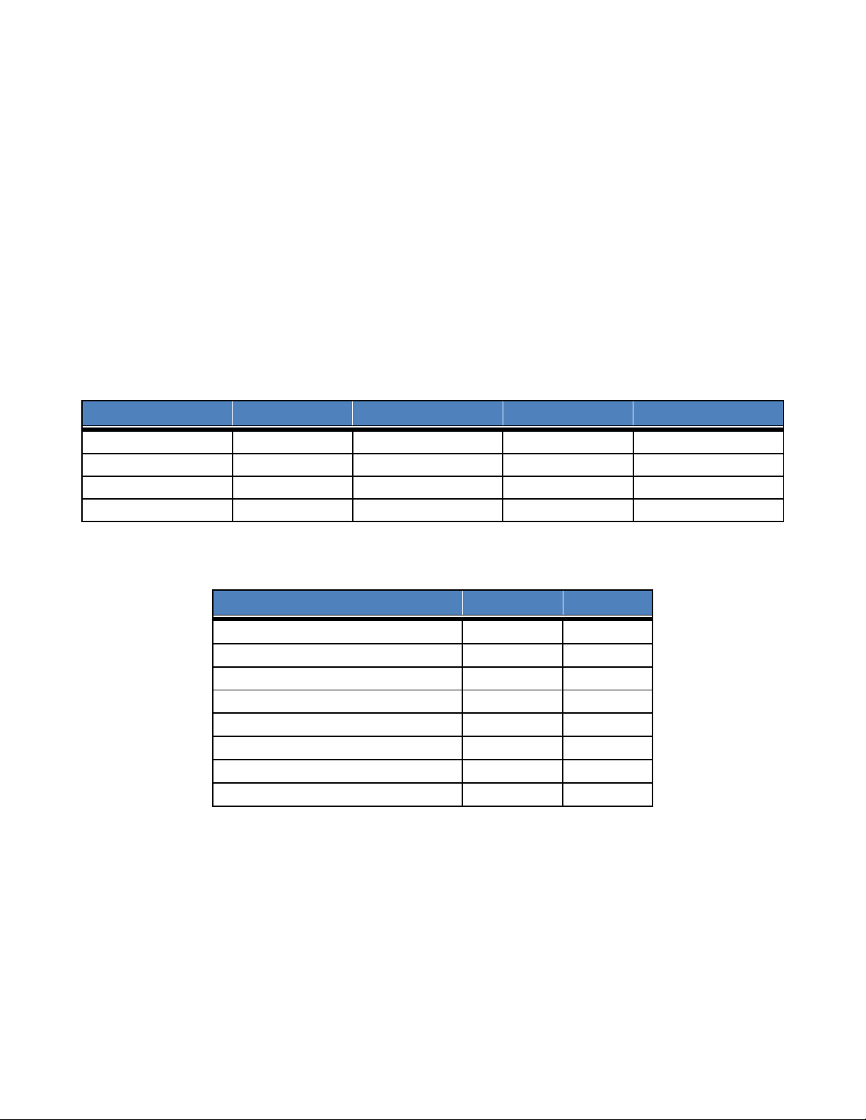
Table 1-1: Smart Room Sensor Models
Family
Module T-Code
LoRaWAN RF Region
Tx (Uplink) Band
Rx (Downlink) Band
Smart Room Base, NA
T0006115
US915
902-915 MHz (ISM)
923-928 MHz (ISM)
Smart Room PIR, NA
T0006116
US915
902-915 MHz (ISM)
923-928 MHz (ISM)
Smart Room Base, DN
T0006163
DN915
902-915 MHz (ISM)
722-728 MHz (DISH)
Smart Room PIR, DN
T0006164
DN915
902-915 MHz (ISM)
722-728 MHz (DISH)
Table 1-2: Smart Room Sensor Functional Variants
Feature
Base Model
PIR Model
Temperature
X
X
Relative Humidity
X
X
Accelerometer
X
X
Light Detection
X
X
Human Motion Detection (PIR)
X
Magnetic Switch
X
X
External Connection
X
Moisture Detection
X
• Temperature & Relative Humidity: Transducer reports temperature and relative
humidity of the local environment.
• Accelerometer: Configurable triggers allow the sensor to detect if it has been moved.
• Light Detection: Light transducer reports the presence or absence of light using a
configurable intensity threshold.
• Motion Detection (PIR): A top mounted PIR transducer detects people moving within the
sensor’s field of view (FoV).

LoRa IoT Smart Room Sensor User Guide T0006338_UG Version 1.2
TEKTELIC Communications Inc. Page 8 of 27
• Magnetic Switch: Digital On/Off sensing with an internal magnetic switch.
• External Connection: In the digital mode, external contacts connected with a short cable
can be monitored for on/off states or used to count events. In the analog mode, a
thermistor can be connected for remote temperature sensing.
• Moisture Detection: Capacitive transducer mounted in the sensor case detects pooling
water under the device for flood or leak detection.
Figure 1-1 illustrates the two Smart Room Sensor functional variants. Both variants share the
same external dimensions (42mm x 42mm x 17mm).
Base Model PIR Model
Figure 1-1: The Smart Room Sensor models.
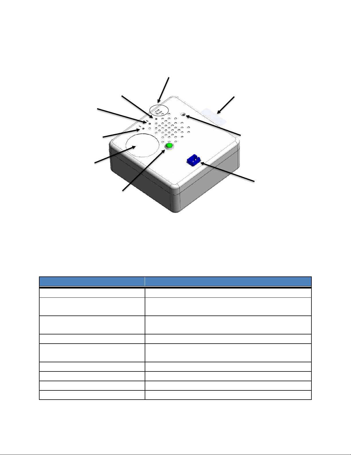
1.2 Physical Interfaces
Figure 1-2 illustrates the customer accessible interfaces for the Smart Room Sensor. All models
share the same layout, though only functional interfaces are exposed in the case of each model.
For example, a Base model has been shown in Figure 1-2, which does not have the PIR element.
Also, the PIR model does not have the External Connector.
LoRa IoT Smart Room Sensor User Guide T0006338_UG Version 1.2
TEKTELIC Communications Inc. Page 9 of 27
Figure 1-2: The Smart Room Sensor external interface layout.
1.3 Specifications
The Smart Room Sensor specifications are listed in Table 1-3.
Table 1-3: Smart Room Sensor Specifications
Parameter
Requirement
Use environment
Indoor commercial/residential only
Operating temperature
0°C‒60°C
10°C‒40°C for optimal battery life
Storage temperature
-30°C‒60°C
0°C‒30°C for optimal battery life
RH
5%‒95%, non-condensing
Size
42 mm x 42 mm x 17 mm (enclosure)
42 mm x 42 mm x 20 mm (with bracket assembly)
Weight
25 g
Power source
Battery operated, with FET based reverse polarity protection.
Network technology/Frequency band
LoRaWAN with US915 and DN915 flavors
Air interface
LoRa
Battery Pull Tab
Reset Button
External Connector
Light Transducer
PIR Transducer
System LED
LoRa LED
Humidity &
Temperature
Magnetic
Switch Area
 Loading...