


TEKTELIC COMMUNICATIONS INC.
Document type:
Document number:
Document version:
Document Status:
Product name:
Product codes:
User Guide
T0004564_UG
0.5
Draft
Enterprise Radio Module
T0004564
TEKTELIC Communications Inc.
7657 10
Calgary, AB, Canada T2E 8X2
Phone: (403) 338-6900
© 2017 TEKTELIC Communications Inc., All rights reserved.
All products, names and services are trademarks and registered trademarks of their respective companies.
Disclaimer:
Material contained in this document is subject to change without notice. The material herein is solely for
information purposes and does not represent a commitment by TEKTELIC or its representatives. TEKTELIC has
prepared the information contained in this document solely for use by its employees, agents, and customers.
Dissemination of this information and/or concepts to other parties is prohibited without the prior written consent
of TEKTELIC. In no event will TEKTELIC be liable for any incidental or consequential damage in connection with the
furnishing, performance or use of this material.
TEKTELIC reserves the right to revise this publication in accordance with formal change control procedures defined
by TEKTELIC.
th
Street NE
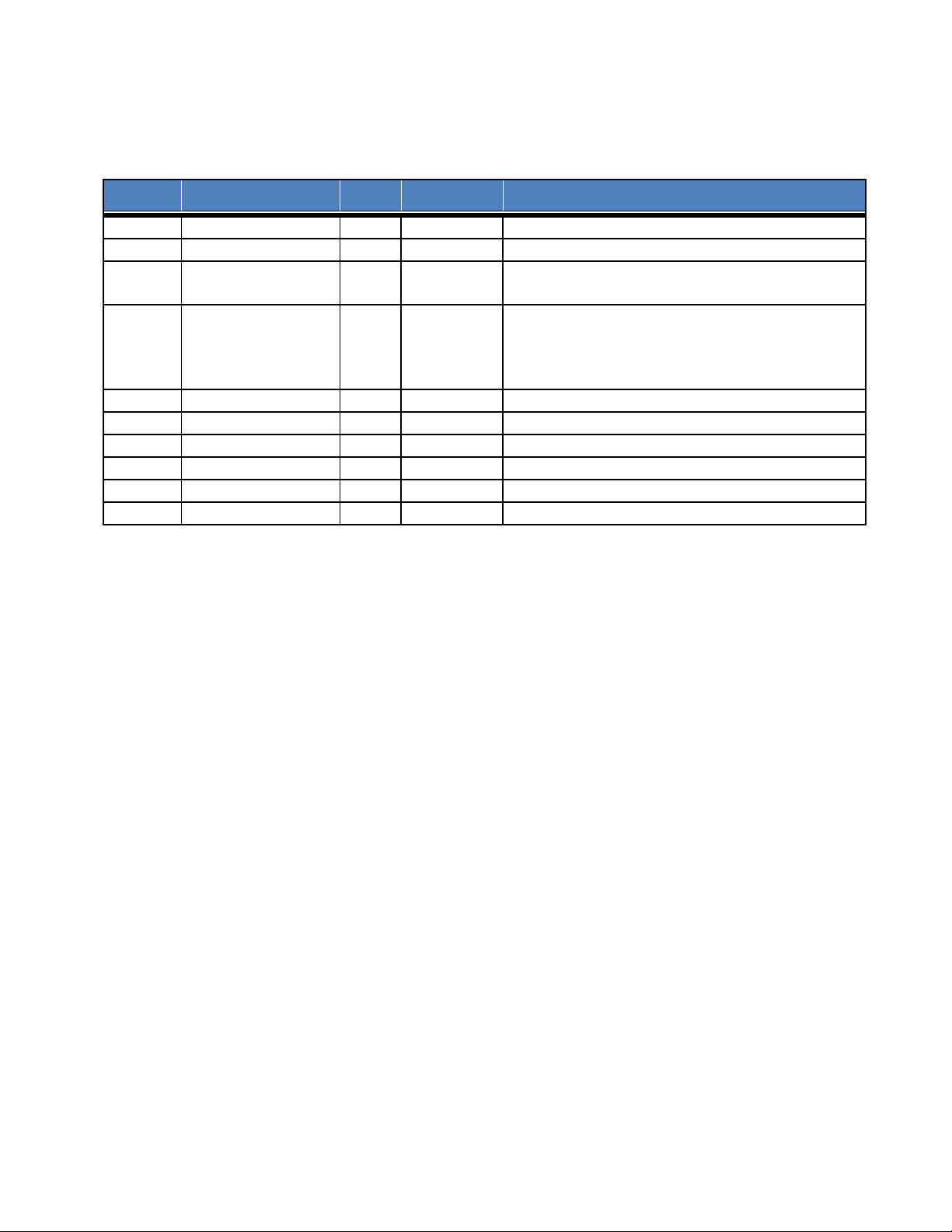
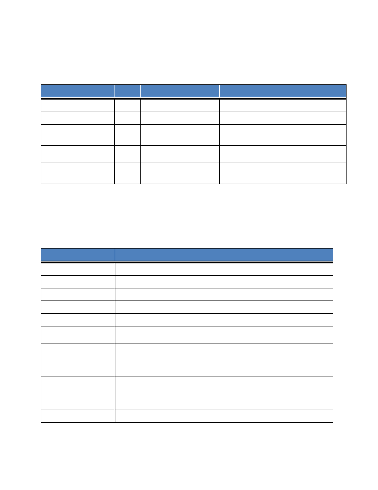
Revision History
Version
Date
Status
Editor
Comments
0.1
September 29, 2017
Draft
H. Agus
First release modified from T0004279_UG
0.2
November 2, 2017
Draft
T. Danshin
Additional updates
Updated minimum separation distances based on
SAR calculations
Response to modular approval requirements
distances based on SAR calculations.
0.5
November 17, 2017
Draft
T. Danshin
Updated French translation
0.3 November 3, 2017 Draft T. Danshin
0.4 November 17, 2017 Draft T. Danshin
corrected to be consistent with modular approval
cover letter. Updated minimum separation
Enterprise Radio Module User Guide T0004564_UG Version 0.5
TEKTELIC Communications Inc. Confidential Page 2 of 28

Table of Contents
1 Product Description ................................................................................................................. 5
1.1 Overview .......................................................................................................................... 5
1.2 External Interfaces ........................................................................................................... 6
1.3 Specifications.................................................................................................................... 8
2 Installation ............................................................................................................................. 10
2.1 Safety Precautions .......................................................................................................... 10
2.2 Unpacking and Inspection .............................................................................................. 10
2.3 Required Equipment for Installation .............................................................................. 11
2.4 Enterprise Radio Mounting ............................................................................................ 11
2.5 Ground Cable Installation .............................................................................................. 11
2.6 Direct DC Power Cable Installation ................................................................................ 11
2.7 RF Cable Installation ....................................................................................................... 12
2.8 Copper Ethernet Cable Installation ................................................................................ 13
3 Radio Compliance Statements .............................................................................................. 14
4 Product Description ............................................................................................................... 17
4.1 Aperçu ............................................................................................................................ 17
4.2 Interfaces externes ......................................................................................................... 18
4.3 Spécifications.................................................................................................................. 20
5 Installation ............................................................................................................................. 22
5.1 Précautions de sécurité .................................................................................................. 22
5.2 Déballage et inspection .................................................................................................. 23
5.3 Matériel requis pour l'installation .................................................................................. 23
5.4 Montage de la radio d'entreprise .................................................................................. 23
5.5 Installation du câble au sol ............................................................................................. 23
5.6 Installation directe du câble d'alimentation CC ............................................................. 24
5.7 Installation du câble RF .................................................................................................. 25
5.8 Installation du câble Ethernet en cuivre ........................................................................ 25
6 Déclarations de conformité radio .......................................................................................... 27
Enterprise Radio Module User Guide T0004564_UG Version 0.5
TEKTELIC Communications Inc. Confidential Page 3 of 28

Enterprise Radio Module User Guide T0004564_UG Version 0.5
TEKTELIC Communications Inc. Confidential Page 4 of 28
1 Product Description
Direct
1
T0004564
ENTERPRISE Radio
1 1 0 1 0
2
1.1 Overview
The Enterprise Radio is a LoRaWAN IoT gateway that supports the full range of US902-928
channels in an outdoor environment (Tx: 923-928MHz, Rx: 902-915MHz). The hardware
architecture supports one or two LoRa antennas, a GPS antenna, direct DC input power and
copper Ethernet backhaul. Table 1-1 shows the Enterprise Radio product information.
Table 1-1: Enterprise Radio Models
Model
Product
Code
Description
GPS
Ant.
DC
Power
Optical
Copper
Eth.
3G/4G
Ant.
LoRa
Ant.
Figure 1 illustrates the Enterprise Radio external form-factor.
The Enterprise radio is a modular radio that is designed to interface to a specific host to form a
custom strand mount LoRa gateway (SLG). TEKELIC manufactures the T0004564 Enterprise
Radio and delivers it to a specific development partner/customer who attaches it to the
dedicated host portion within a matching mechanical chassis half to realize a complete SLG.
The mechanical chassis of the host is custom designed to interface perfectly with the Enterprise
radio to realize a fully integrated strand mounted gateway. The Enterprise Radio will not fit
with or mechanically mate to any other host device by design.
The required host supply voltage and current capability is: 5Vdc ±5%, 6.5A (Table 1-3)
The data communication interface requirement is 100/1000BT Ethernet. The connector
interface is defined in Table 2-2. During normal operation the Ethernet interface shall provide
access to the internet for the Enterprise radio module to connect to a LoRaWAN network
server.
Enterprise Radio Module User Guide T0004564_UG Version 0.5
TEKTELIC Communications Inc. Confidential Page 5 of 28
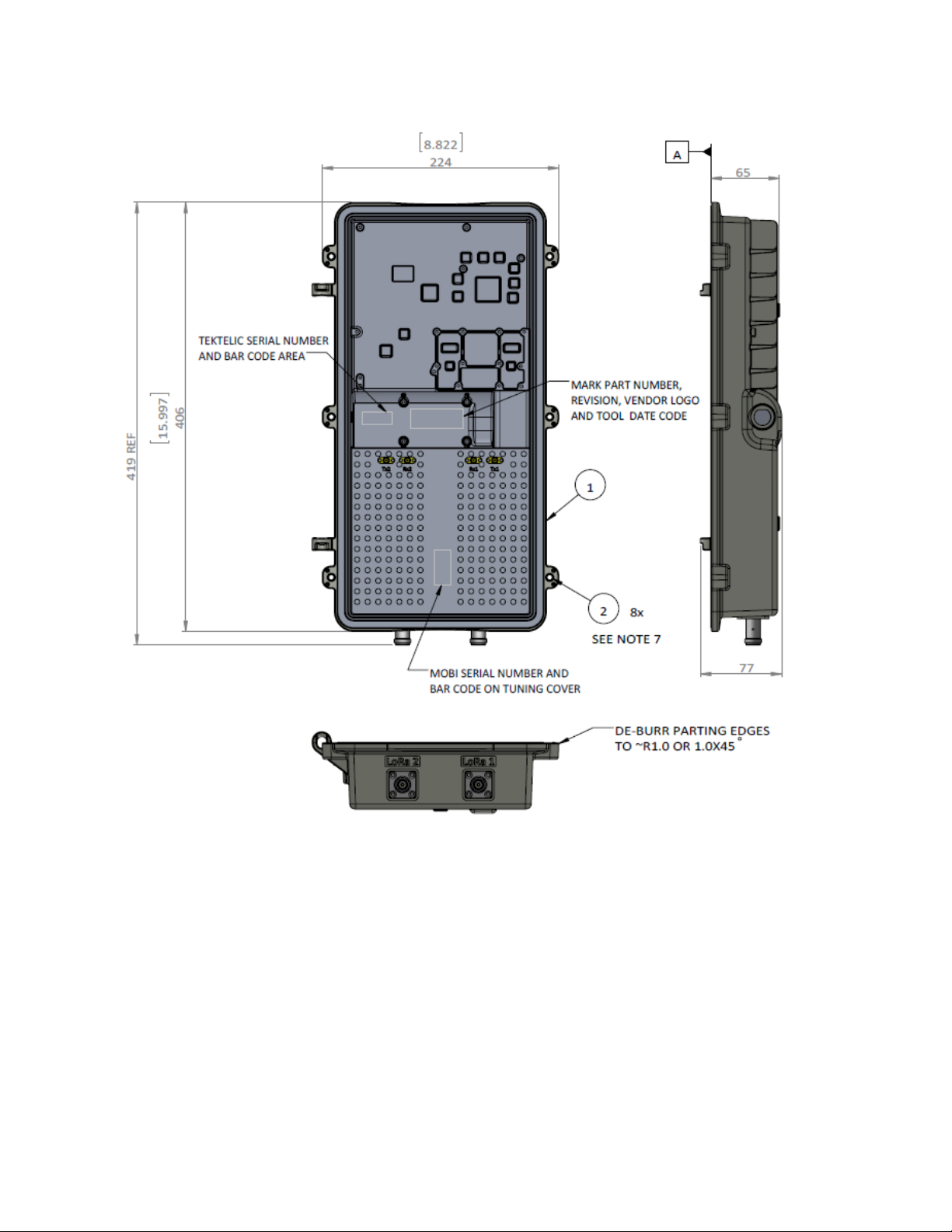
Figure 1: Enterprise Radio
1.2 External Interfaces
The Enterprise Gateway external interconnect is illustrated in Figure 2 and Figure 3. In Figure 2,
the GPS antenna connection is labelled “14” and the two other N-type connectors shown are
the LoRa RF interfaces. Figure 4 shows the connections to the specific host portion of the SLG.
The 5V input DC power cable is shown on the lower left of the figure and a RJ45 Ethernet
connector is shown above the cable.
Enterprise Radio Module User Guide T0004564_UG Version 0.5
TEKTELIC Communications Inc. Confidential Page 6 of 28
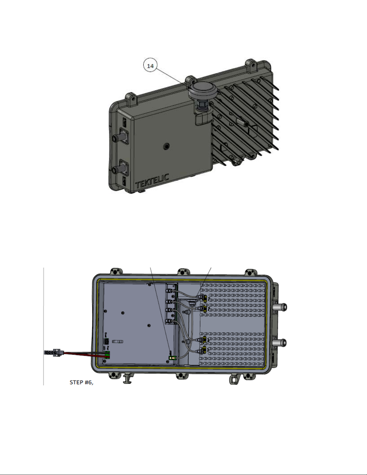
Figure 2: Enterprise Radio External Connectors
Figure 3: Enterprise Radio External Host Connections
Enterprise Radio Module User Guide T0004564_UG Version 0.5
TEKTELIC Communications Inc. Confidential Page 7 of 28
The RF connectors are water proof while un-mated. Connector types and their mating
Interface
QTY
Connector Type
Mating Connector
LoRa Antenna Ports
2
N-Type female
Industry standard N-Type male
1
N-Type female
Industry standard N-Type male
Molex 87831-0841 Pin
Direct DC Power Input
Port
Chassis Protective Earth
Industry standard 2-hole lug, 1/4 x 0.75”
Attribute
Specification
Dimensions
65mm (2.6”) wide x 406mm (16.0”) deep x 224mm (8.8”) tall
Weight
3.9 kg (8.6 lbs)
-40°C to 60°C (-40°F to 140°F) at sea level Including solar loading.
10% to 100%
-60 m to 4,000 m (-197 ft to 13,123 ft)
Host Supply Voltage
and Current Capability
35 W maximum, 7.0 A maximum with direct DC powering
UL Type 6 (IP-67) – when matched with host portion to make an integrated
CSA/UL 60950-1 & CSA/UL 60950-22
All RF interfaces are protected to primary levels
connectors are listed in Table 1-2.
Table 1-2: Enterprise Radio Interface Connector Types
GPS Port
Copper Ethernet Port 1
0 or 1 TE: 1-480702-0 TE 770351-1, TE643415-1
Earth Ground
Header
1
Ground terminal
1.3 Specifications
The Enterprise Radio specifications are listed in Table 1-3.
Table 1-3: Enterprise Radio Specifications
Operating Temperature
Relative Humidity
Molex 0511100850 or equivalent
spacing
Operating Altitude
5Vdc ±5%, 6.5A
Power Consumption
Weather Tightness
Regulatory Compliance
Surge Protection
SLG.
FCC Pt. 15.109 Class B (when mated with host portion to form complete
SLG)
Enterprise Radio Module User Guide T0004564_UG Version 0.5
TEKTELIC Communications Inc. Confidential Page 8 of 28
This radio transmitter in the Enterprise Radio, IC: 22504-T0004564, FCC ID: 2ALEPT0004564, has
Gateway
Antenna
Enterprise
IC: 22504-T0004564,
Enterprise
IC: 22504-T0004564,
been approved by Industry Canada to operate with the antenna types listed below with the
maximum permissible gain indicated. Antenna types not included in this list, having a gain
greater than the maximum gain indicated for that type, are strictly prohibited for use with this
device.
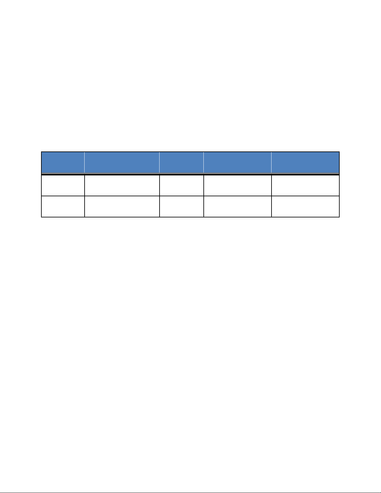
The specified ISM antennas are listed in Table 1-4. Antenna types not included in Table 1-4,
having a gain greater than the maximum gain indicated for that type, are strictly prohibited for
use with this device.
Table 1-4 ISM Antennas
Type
Radio
Radio
ID
FCC ID: 2ALEPT0004564
FCC ID: 2ALEPT0004564
Vendor
Airgain CH2P900 3.5
L-Com HGV906U 6
Model Number Gain (dBi)
Enterprise Radio Module User Guide T0004564_UG Version 0.5
TEKTELIC Communications Inc. Confidential Page 9 of 28

2 Installation
2.1 Safety Precautions
• Installation, operation, and maintenance of the Enterprise Radio must only be performed by
a professionally trained service technician who is aware of all hazards involved.
• The Enterprise Radio must be installed in a restricted access location (such that touching of
the Gateway by non-service persons is not likely).
• The Enterprise Radio may become hot to the touch during normal operation at elevated
ambient temperatures. The surface temperature of the Gateway may reach 90°C.
• The Enterprise Radio has no internal field serviceable parts. The Gateway module must only
be opened by an approved TEKTELIC service center.
• All installation practices must be in accordance with the local and national electrical codes.
• Do not work on the system during periods of lightning activity.
• The Enterprise Radio is considered permanently connected equipment. The Protective Earth
Ground connection through the dedicated host chassis is always required.
• The Enterprise Radio contains primary lightning surge suppression on the GPS antenna port
and the LoRa RF antenna ports. The primary lightning protectors have the ability to bridge
the interface isolation boundary during over-voltages. Ensure that the Protective Earth
Ground connection through the dedicated host is always in place.
• Ensure that the Enterprise Radio, its antennas and supporting structures are properly
secured to eliminate any physical hazard to people or property. The Gateway must be
securely mounted according to the mounting instructions prior to any cable connection and
operation.
• The direct DC powered Enterprise Radio does not require an input overcurrent protection
device since it contains a 10A input fuse.
• The DC positive pin must be at positive potential relative to the DC negative pin. If the
polarity is reversed, the unit will sustain damage.
• The Enterprise Radio power source must meet SELV requirements.
2.2 Unpacking and Inspection
The following should be considered during the unpacking of a new Enterprise Radio:
1. Inspect the shipping carton and report any significant damage to TEKTELIC.
Enterprise Radio Module User Guide T0004564_UG Version 0.5
TEKTELIC Communications Inc. Confidential Page 10 of 28

2. Unpacking should be conducted in a clean and dry location when possible.
3. Do not discard the shipping box or foam inserts as they will be required if a unit is
returned for repair or re-configuration.
2.3 Required Equipment for Installation
The following tools are required to install the Enterprise Radio module:
1. A 6 point metric socket set and torque wrench drive.
2. Anti-oxidant compound (NO-OX-ID, Penetrox, Noalox, Ox-Gard or equivalent).
3. A small wire brush.
4. A clean cloth.
5. Weatherproofing tape kit for the RF connectors (Scotch Wireless Weatherproofing Kit,
WK-101 recommended).
2.4 Enterprise Radio Mounting
Enterprise Radio is designed to be mated to the host portion of the SLG. Mounting to the cable
strand is not specified in this document but is covered in the SLG installation documentation.
The Enterprise Radio chassis is specifically designed to be mounted only to the mechanically
matched host portion to form a complete SLG unit.
2.5 Ground Cable Installation
The Enterprise Radio is considered Permanently Connected Equipment and requires a
permanently connected Protective Earth Ground (PEG) connection. The Protective Earth
Ground connection is made through the chassis to the host portion of the SLG module. The
host half of the SLG module has a 1/4 x 0.75” on center double hole lug to the ground
termination point. The ground cable gauge on the SLG point shall be #10 AWG minimum.
Proper routing and termination of this cable is key to robust lightning withstand performance;
in high susceptibility installations, every effort shall be made to minimize connection
inductance and ground bed resistance.
2.6 Direct DC Power Cable Installation
The Enterprise Radio direct DC input feed cable terminates at a dedicated 4 pin TE: 1-480702-0
plastic connector illustrated in Figure 4. The direct DC power input is isolated from chassis
(earth) and incorporates a 10A input fuse on the Enterprise Radio.
The DC power interface follows the signal polarity identified in Figure 4 and Table 2-1.
Enterprise Radio Module User Guide T0004564_UG Version 0.5
TEKTELIC Communications Inc. Confidential Page 11 of 28

Enterprise
Pin 1
Red
J60
Input Pwr: +5V DC
Pin 2
Black
J61
GND
Pin 3
Blue
J58
LED Out Pin 3
Pin 4
Brown
J59
LED Out Pin 4
Figure 4: DC Power Connector Connection Polarity
Table 2-1 DC Power Connector Pin Assignments
Cable Pin # Wire Color
2.7 RF Cable Installation
The Gateway installation will require connection to a GPS antenna and two LoRa RF antennas.
The RF cables attach to the N-Type connectors on the bottom of the Enterprise Radio. Torque
the connectors to 1.7 to 2.3 Nm (15 to 20 in·lbs). The N-Type connector interface to a cable is
not water proof and must be taped to be used outdoors. TEKTELIC recommends taping with
Enterprise Radio Module User Guide T0004564_UG Version 0.5
TEKTELIC Communications Inc. Confidential Page 12 of 28
Radio Pin #
Description

Scotch Wireless Weatherproofing Kit, WK-101. Follow the taping procedures outlined by the
Enterprise
RJ45 Pin
0P 8 1
A+
White/Orange (stripe)
0N 7 2
A-
Orange (solid)
1P 6 3
B+
White/Green (stripe)
2P 3 4
C+
Blue (solid)
2N 4 5
C-
White/Blue (stripe)
1N 5 6
B-
Green (solid)
3P 1 7
D+
White/Brown (stripe)
3N 2 8
D-
Brown (solid)
supplier of this tape system.
2.8 Copper Ethernet Cable Installation
The Ethernet cable must have minimum 24 AWG conductors and shall be rated for outdoor
application according to local and national electrical codes. The mapping of pins between the
Molex 87831-0841 Pin Header and a TIA-568B RJ45 pin assignment is listed in Table 2-2.
Table 2-2 Ethernet Interface Pin Assignments
Radio
Ethernet
Signal
Descrption
Enterprise
Radio Pin #
RJ45 Pin #
Description
Standard Wire Color Assignment
Enterprise Radio Module User Guide T0004564_UG Version 0.5
TEKTELIC Communications Inc. Confidential Page 13 of 28

3 Radio Compliance Statements
Federal Communications Commission
This device complies with Part 15 of the FCC Rules. Operation is subject to the following two
conditions:
1. This device may not cause harmful interference, and
2. This device must accept any interference received, including interference that may
cause undesired operation.
Changes or modifications not expressly approved by the party responsible for compliance
could void the user’s authority to operate the equipment.
The FCC label shall be visible from the outside of the end product.
It is the responsibility of the SLG host manufacturer to ensure compliance of the complete SLG
unit with the limits for a Class B digital device, pursuant to Part 15 of the FCC Rules. These
limits are designed to provide reasonable protection against harmful interference in a
residential installation. This equipment generates uses and can radiate radio frequency energy
and, if not installed and used in accordance with the instructions, may cause harmful
interference to radio communications. However, there is no guarantee that interference will
not occur in a particular installation. If this equipment does cause harmful interference to
radio or television reception, which can be determined by turning the equipment off and on,
the user is encouraged to try to correct the interference by one of the following measures:
• Reorient or relocate the receiving antenna.
• Increase the separation between the equipment and receiver.
• Connect the equipment into an outlet on a circuit different from that to which the
receiver is connected.
• Consult the dealer or an experienced radio/TV technician for help.
Only antenna type Omnidirectional with a gain of 6 dBi or lower can be use with this product.
To comply with FCC/IC RF exposure limits for general population / uncontrolled exposure, the
antennas used for this Enterprise Radio transmitter must be installed to provide a separation
distance of at least 22.5 cm from all persons and must not be co-located or operating in
conjunction with any other antenna or transmitter.
The Enterprise Radio Module meets the limited modular requirements information listed in
KDB 996369 § III. a).
Enterprise Radio Module User Guide T0004564_UG Version 0.5
TEKTELIC Communications Inc. Confidential Page 14 of 28

The specific limitations are that the Enterprise Radio module shall only be connected to a
specific custom designed host that shares a custom designed matching mechanical chassis to
realize a fully integrated SLG module and that the SLG module containing the Enterprise Radio
Module must be professionally installed. The specific host provides power supply regulation
and additional shielding of non-RF signals from the Enterprise Radio Module. The remainder of
the modular requirements are met without limitation:
• The radio elements have the radio frequency circuitry shielded.
• The Enterprise Radio module has buffered modulation/data inputs to ensure that the
device will comply with Part 15 requirements with any type of input signal
• The antenna requirements of §§ 15.203 (via professional installation), 15.204(b),
15.204(c), 15.212(a), 2.929(b) are met. (This product is compliant to § 15.204 b) and c)
since it will only be marketed as a system that includes the 2ALEPT0004564 module
and the specific antennas listed in Table 1-4. Control of the end product into which the
module will be installed will be maintained via professional installation)
• The Enterprise Radio module is labeled with its permanently affixed FCC ID label
• Compliance with all specific rules applicable to the transmitter is ensured through
professional installation
• The Enterprise Radio module complies with RF exposure requirements
The Enterprise Radio module complies with RF exposure requirements
Industry Canada
This Device complies with Industry Canada License-exempt RSS standard(s). Operation is
subject to the following two conditions:
1. This device may not cause interference, and
2. This device must accept any interference, including interference that may cause
undesired operation of the device.
This radio transmitter IC: 22504-T0004564 has been approved by Industry Canada to operate
with the antenna types listed in Table 1-4 with the maximum permissible gain indicated.
Antenna types not included in this list, having a gain greater than the maximum gain indicated
for that type, are strictly prohibited for use with this device.
Enterprise Radio Module User Guide T0004564_UG Version 0.5
TEKTELIC Communications Inc. Confidential Page 15 of 28

The antenna requirements are:
• Impedance: 50 Ohms.
• type: omni directional (dipole)
• Maximum gain: 6 dBi
Antenna(s) shall be installed to location providing a separation distance of at least 13.2 inches
(33.5 cm) from any human body.
The product must be installed by professional trained RF technicians.
During product operation, always keep a separation distance of at least 13.2 inches (33.5 cm)
from any connected antenna(s). Before servicing the product, the antenna(s) or cables, turn
off the transmission function or the unit power if you have to get closer than the minimum
separation distance.
The Enterprise Radio Module meets the limited modular requirement information listed in
RSP-100. The specific limitations are that the Enterprise Radio module shall only be
connected to a specific custom designed host that shares a custom designed matching
mechanical chassis to realize a fully integrated SLG module. The specific host provides power
supply regulation and additional shielding of non-RF signals from the Enterprise Radio
Module. The remainder of the modular requirements are met without limitation:
• The radio elements have the radio frequency circuitry shielded.
• The Enterprise Radio module has buffered modulation/data inputs to ensure that the
device will comply with RSS-247 requirements with any type of input signal
• The module shall comply with the provisions for external power amplifiers and
antennas detailed in the applicable RSS. This user guide contains a detailed description
of the configuration of highest antenna gain for each type of antenna.
• The Enterprise Radio module complies with RF exposure requirements
Enterprise Radio Module User Guide T0004564_UG Version 0.5
TEKTELIC Communications Inc. Confidential Page 16 of 28

4 Product Description
Direct
1
T0004564
ENTERPRISE Radio
1 1 0 1 0
2
4.1 Aperçu
Enterprise Radio est une passerelle LoRaWAN IoT qui prend en charge toute la gamme des
canaux US902-928 dans un environnement extérieur. L'architecture matérielle prend en charge
une ou deux antennes LoRa, une antenne GPS, une alimentation d'entrée CC directe et un
backhaul Ethernet cuivre. Le tableau 4-1 montre les informations sur le produit Enterprise
Radio.
Table 4-1: Modèles de radio d'entreprise
Model
Product
Code
Description
GPS
Ant.
DC
Power
Optical
Copper
Eth.
3G/4G
Ant.
LoRa
Ant.
La Figure 5 illustre le facteur de forme externe de Enterprise Radio.
La radio d'entreprise est une radio modulaire qui est conçue pour s'interfacer avec un hôte
spécifique afin de former une passerelle LoRa personnalisée (SLG). TEKELIC fabrique la radio
d'entreprise T0004564 et la livre à un partenaire / client de développement spécifique qui
l'attache à la partie hôte dédiée dans une moitié de châssis mécanique correspondante pour
réaliser une SLG complète. Le châssis mécanique de l'hôte est conçu sur mesure pour
s'interfacer parfaitement avec la radio Enterprise pour réaliser une passerelle entièrement
intégrée. La radio d'entreprise ne s'adaptera pas mécaniquement à un autre périphérique hôte.
La tension d'alimentation hôte et la capacité de courant requises sont: 5Vdc ± 5%, 6.5A.
L'exigence d'interface de communication de données est Ethernet 100 / 1000BT. L'interface du
connecteur est définie dans le Tableau 5-2. En fonctionnement normal, l'interface Ethernet doit
permettre l'accès à Internet pour que le module radio Enterprise se connecte à un serveur
réseau LoRaWAN.
Enterprise Radio Module User Guide T0004564_UG Version 0.5
TEKTELIC Communications Inc. Confidential Page 17 of 28

Figure 5: Radio d'entreprise
4.2 Interfaces externes
L'interconnexion externe Enterprise Gateway est illustrée à la figure 6 et à la figure 7. Sur la
figure 6, la connexion de l'antenne GPS est marquée «14» et les deux autres connecteurs de
type N représentés sont les interfaces RF LoRa. La figure 7 montre les connexions à la partie
hôte spécifique de la SLG. Le câble d'alimentation CC d'entrée 5V est indiqué en bas à gauche
de la figure et un connecteur Ethernet RJ45 est affiché au-dessus du câble.
Enterprise Radio Module User Guide T0004564_UG Version 0.5
TEKTELIC Communications Inc. Confidential Page 18 of 28

Figure 6: Enterprise Radio External Connectors
Figure 7:
Connexions d'hôte externe de la radio d'entreprise
Enterprise Radio Module User Guide T0004564_UG Version 0.5
TEKTELIC Communications Inc. Confidential Page 19 of 28

Les connecteurs RF sont à l'épreuve de l'eau lorsqu'ils sont démontés. Les types de connecteurs
Interface
QTY
Connector Type
Mating Connector
LoRa Antenna Ports
2
N-Type female
Industry standard N-Type male
1
N-Type female
Industry standard N-Type male
Molex 87831-0841 Pin
Direct DC Power Input
Port
Chassis Protective Earth
Industry standard 2-hole lug, 1/4 x 0.75”
Attribute
Specification
Dimensions
65mm (2.6”) wide x 406mm (16.0”) deep x 224mm (8.8”) tall
Weight
3.9 kg (8.6 lbs)
-40°C to 60°C (-40°F to 140°F) at sea level Including solar loading.
10% to 100%
-60 m to 4,000 m (-197 ft to 13,123 ft)
Host Supply Voltage
and Current Capability
35 W maximum, 7.0 A maximum with direct DC powering
UL Type 6 (IP-67) – when matched with host portion to make an integrated
CSA/UL 60950-1 & CSA/UL 60950-22
All RF interfaces are protected to primary levels
et leurs connecteurs correspondants sont répertoriés dans le Tableau 4-2.
Table 4-2: Types de connecteurs d'interface radio d'entreprise
GPS Port
Copper Ethernet Port 1
0 or 1 TE: 1-480702-0 TE 770351-1, TE643415-1
Earth Ground
1
Header
Ground terminal
Molex 0511100850 or equivalent
spacing
4.3 Spécifications
Les spécifications Enterprise Radio sont répertoriées dans le Tableau 4-3.
Table 4-3: Enterprise Radio Spécifications
Operating Temperature
Relative Humidity
Operating Altitude
5Vdc ±5%, 6.5A
Power Consumption
Weather Tightness
Regulatory Compliance
Surge Protection
SLG.
FCC Pt. 15.109 Class B (when mated with host portion to form complete
SLG)
Enterprise Radio Module User Guide T0004564_UG Version 0.5
TEKTELIC Communications Inc. Confidential Page 20 of 28

Cet émetteur radio de la radio d'entreprise, IC: 22504-T0004564, a été approuvé par Industrie
Gateway
Antenna
Enterprise
Enterprise
Canada pour fonctionner avec les types d'antenne énumérés ci-dessous avec le gain maximal
admissible indiqué. Les types d'antennes non inclus dans cette liste, dont le gain est supérieur
au gain maximal indiqué pour ce type, sont strictement interdits pour une utilisation avec cet
appareil.
Les antennes ISM spécifiées sont répertoriées dans le Tableau 4-4. Les types d'antennes non
inclus dans le tableau 4-4, ayant un gain supérieur au gain maximal indiqué pour ce type, sont
strictement interdits pour une utilisation avec cet appareil.
Table 4-4 Antennes ISM
Type
Radio
Radio
IC: Number
IC: 22504-T0004564 Airgain CH2P900 3.5
IC: 22504-T0004564 L-Com HGV906U 6
Vendor
Model Number Gain (dBi)
Enterprise Radio Module User Guide T0004564_UG Version 0.5
TEKTELIC Communications Inc. Confidential Page 21 of 28

5 Installation
5.1 Précautions de sécurité
• L'installation, le fonctionnement et la maintenance de la radio d'entreprise doivent être
effectués uniquement par un technicien de maintenance qualifié et conscient de tous les
risques impliqués.
• La radio d'entreprise doit être installée dans un emplacement à accès restreint (de sorte
que le contact avec la passerelle par des personnes qui ne sont pas en service est peu
probable).
• La radio d'entreprise peut devenir chaude au toucher pendant le fonctionnement normal à
des températures ambiantes élevées. La température de surface de la passerelle peut
atteindre 90 ° C.
• La radio d'entreprise n'a pas de pièces internes réparables sur site. Le module Gateway ne
doit être ouvert que par un centre de service agréé TEKTELIC.
• Toutes les pratiques d'installation doivent être conformes aux codes électriques locaux et
nationaux.
• Ne travaillez pas sur le système pendant les périodes d'activité de la foudre.
• La radio d'entreprise est considérée comme un équipement connecté en permanence. La
connexion de mise à la terre de protection via le châssis hôte dédié est toujours requise.
• La radio d'entreprise contient une suppression de surtension par foudre primaire sur le port
d'antenne GPS et les ports d'antenne RF LoRa. Les parafoudres primaires ont la capacité de
franchir la frontière d'isolation de l'interface pendant les surtensions. Assurez-vous que la
connexion de mise à la terre de protection via l'hôte dédié est toujours en place.
• Assurez-vous que la radio d'entreprise, ses antennes et ses structures de soutien sont
correctement sécurisées afin d'éliminer tout risque physique pour les personnes ou les
biens. La passerelle doit être montée de manière sécurisée conformément aux instructions
de montage avant toute connexion et opération du câble.
• La radio d'entreprise à alimentation CC directe ne nécessite pas de dispositif de protection
contre les surintensités d'entrée car elle contient un fusible d'entrée de 10 A.
• La broche positive DC doit être à un potentiel positif par rapport à la broche négative DC. Si
la polarité est inversée, l'unité subira des dommages.
• La source d'alimentation Enterprise Radio doit répondre aux exigences SELV.
Enterprise Radio Module User Guide T0004564_UG Version 0.5
TEKTELIC Communications Inc. Confidential Page 22 of 28

5.2 Déballage et inspection
Les éléments suivants doivent être pris en compte lors du déballage d'une nouvelle radio
d'entreprise:
4. Inspecter le carton d'expédition et signaler tout dommage important à TEKTELIC.
5. Le déballage doit être effectué dans un endroit propre et sec lorsque cela est possible.
6. Ne jetez pas la boîte d'expédition ou les inserts en mousse car ils seront nécessaires si
une unité est retournée pour réparation ou reconfiguration..
5.3 Matériel requis pour l'installation
Les outils suivants sont requis pour installer le module Enterprise Radio:
1. Un jeu de douilles métriques à 6 points et une clé dynamométrique.
2. Composé anti-oxydant (NO-OX-ID, Penetrox, Noalox, Ox-Gard ou équivalent).
3. Une petite brosse métallique.
4. Un chiffon propre.
5. Kit de bande de protection contre les intempéries pour les connecteurs RF (kit de
protection contre les intempéries sans fil Scotch, WK-101 recommandé).
5.4 Montage de la radio d'entreprise
La radio d'entreprise est conçue pour être couplée à la partie hôte de la SLG. Le montage sur le
brin de câble n'est pas spécifié dans ce document mais est couvert dans la documentation
d'installation SLG. Le châssis Enterprise Radio est spécifiquement conçu pour être monté
uniquement sur la partie hôte couplée mécaniquement pour former une unité SLG complète.
5.5 Installation du câble au sol
La radio d'entreprise est considérée comme un équipement connecté en permanence et
nécessite une connexion de terre de protection (PEG) connectée en permanence. La connexion
de mise à la terre de protection est effectuée via le châssis vers la partie hôte du module SLG.
La moitié hôte du module SLG a une cosse double trou centrale de 1/4 x 0,75 "au point de
terminaison au sol. La jauge du câble de masse sur le point SLG doit être au minimum de 10
AWG.
Un routage et une terminaison adéquats de ce câble sont la clé d'une performance de tenue à
la foudre robuste; dans les installations à haute susceptibilité, tout doit être mis en œuvre pour
minimiser l'inductance de la connexion et la résistance au sol.
Enterprise Radio Module User Guide T0004564_UG Version 0.5
TEKTELIC Communications Inc. Confidential Page 23 of 28

5.6 Installation directe du câble d'alimentation CC
Le câble d'alimentation d'entrée directe DC Enterprise Radio se termine par un connecteur en
plastique TE: 1-480702-0 4 broches illustré à la Figure 4. L'entrée d'alimentation CC directe est
isolée du châssis (terre) et intègre un fusible d'entrée de 10 A sur la radio d'entreprise.
L'interface d'alimentation CC suit la polarité du signal identifiée dans la Figure 8 et le Tableau 5-
1.
Figure 8: Polarité de connexion du connecteur d'alimentation CC
Enterprise Radio Module User Guide T0004564_UG Version 0.5
TEKTELIC Communications Inc. Confidential Page 24 of 28

Table 5-1 Affectations des broches du connecteur d'alimentation CC
Enterprise
Pin 1
Red
J60
Input Pwr: +5V DC
Pin 2
Black
J61
GND
Pin 3
Blue
J58
LED Out Pin 3
Pin 4
Brown
J59
LED Out Pin 4
Cable Pin # Wire Color
Radio Pin #
Description
5.7 Installation du câble RF
L'installation de la passerelle nécessitera une connexion à une antenne GPS et à deux antennes
RF LoRa. Les câbles RF se connectent aux connecteurs de type N situés au bas de la radio
d'entreprise. Serrez les connecteurs de 1,7 à 2,3 Nm (15 à 20 po · lbs). L'interface du connecteur
de type N à un câble n'est pas étanche et doit être scellée pour être utilisée à l'extérieur.
TEKTELIC recommande de scotcher avec le kit d'imperméabilisation sans fil Scotch, WK-101.
Suivez les procédures d'enregistrement décrites par le fournisseur de ce système de bande.
5.8 Installation du câble Ethernet en cuivre
Le câble Ethernet doit avoir un minimum de 24 conducteurs AWG et doit être classé pour une
application extérieure conformément aux codes électriques locaux et nationaux. Le mappage
des broches entre l'en-tête de broche Molex 87831-0841 et une affectation de broche TIA-568B
RJ45 est répertorié dans le Tableau 5-2.
Enterprise Radio Module User Guide T0004564_UG Version 0.5
TEKTELIC Communications Inc. Confidential Page 25 of 28

Table 5-2 Affectations des broches de l'interface Ethernet
Enterprise
RJ45 Pin
0P 8 1
A+
White/Orange (stripe)
0N 7 2
A-
Orange (solid)
1P 6 3
B+
White/Green (stripe)
2P 3 4
C+
Blue (solid)
2N 4 5
C-
White/Blue (stripe)
1N 5 6
B-
Green (solid)
3P 1 7
D+
White/Brown (stripe)
3N 2 8
D-
Brown (solid)
Radio
Ethernet
Signal
Descrption
Enterprise
Radio Pin #
RJ45 Pin #
Description
Standard Wire Color Assignment
Enterprise Radio Module User Guide T0004564_UG Version 0.5
TEKTELIC Communications Inc. Confidential Page 26 of 28

6 Déclarations de conformité radio
Industrie Canada
Le présent appareil est conforme aux CNR d'Industrie Canada applicables aux appareils radio
exempts de licence. L'exploitation est autorisée aux deux conditions suivantes : (1) l'appareil
ne doit pas produire de brouillage, et (2) l'utilisateur de l'appareil doit accepter tout brouillage
radioélectrique subi, même si le brouillage est susceptible d'en compromettre le
fonctionnement.
Cet émetteur radio IC: 22504-T0004564 a été approuvé par Industrie Canada pour fonctionner
avec les types d'antenne énumérés avec le gain maximal admissible indiqué. Les types
d'antennes non inclus dans cette liste, dont le gain est supérieur au gain maximal indiqué pour
ce type, sont strictement interdits pour une utilisation avec cet appareil.
Les requis de l`antenne a utilise sont:
• Impedance: 50 Ohms
• Type: dipole
• Gain maximum: 6 dBi
Les antennes doivent être installées à un endroit offrant une distance de séparation d'au
moins 13,2 pouces (33,5 cm) de tout corps humain. Le produit doit être installé par des
techniciens RF qualifiés.
Pendant le fonctionnement du produit, gardez toujours une distance de séparation d'au
moins 13,2 pouces (33,5 cm) de toute antenne connectée. Avant de réparer le produit,
l'antenne ou les câbles, désactivez la fonction de transmission ou l'alimentation de l'unité si
vous devez vous rapprocher de la distance de séparation minimale.
Le module radio d'entreprise répond aux exigences d'exigences modulaires limitées
énumérées dans RSP-100. Les limitations spécifiques sont que le module Enterprise Radio ne
doit être connecté qu'à un hôte spécifique conçu sur mesure qui partage un châssis
mécanique adapté conçu sur mesure pour réaliser un module SLG entièrement intégré. L'hôte
spécifique fournit une régulation de l'alimentation et un blindage supplémentaire des signaux
non RF provenant du module radio d'entreprise. Le reste des exigences modulaires sont
satisfaites sans limitation:
• Les éléments radio ont les circuits radiofréquences blindés.
• Le module Enterprise Radio a des entrées de modulation / données tamponnées pour
garantir que l'appareil sera conforme aux exigences RSS-247 avec tout type de signal
d'entrée
Enterprise Radio Module User Guide T0004564_UG Version 0.5
TEKTELIC Communications Inc. Confidential Page 27 of 28

• Le module doit être conforme aux dispositions relatives aux amplificateurs de
puissance externes et aux antennes détaillées dans le RSS applicable. Ce guide de
l'utilisateur contient une description détaillée de la configuration du gain d'antenne le
plus élevé pour chaque type d'antenne.
Le module Enterprise Radio est conforme aux exigences d'exposition RF.
Enterprise Radio Module User Guide T0004564_UG Version 0.5
TEKTELIC Communications Inc. Confidential Page 28 of 28
 Loading...