

TEKTELIC Communications T0004437, T0004438, T0004372 User Manual

TEKTELIC COMMUNICATIONS INC.
Document type:
Document number:
Document version:
Document Status:
Product name:
Product codes:
User Manual
T0004906
1.6
Approved
Pearl Gateway
T0004437, T0004438, T0004372
TEKTELIC Communications Inc.
7657 10
Calgary, AB, Canada T2E 8X2
Phone: (403) 338-6900
© 2017 TEKTELIC Communications Inc., All rights reserved.
All products, names and services are trademarks and registered trademarks of their respective companies.
Disclaimer:
Material contained in this document is subject to change without notice. The material herein is solely for
information purposes and does not represent a commitment by TEKTELIC or its representatives. TEKTELIC has
prepared the information contained in this document solely for use by its employees, agents, and customers.
Dissemination of this information and/or concepts to other parties is prohibited without the prior written consent
of TEKTELIC. In no event will TEKTELIC be liable for any incidental or consequential damage in connection with the
furnishing, performance or use of this material.
TEKTELIC reserves the right to revise this publication in accordance with formal change control procedures defined
by TEKTELIC.
th
Street NE

Revision History
Version
Date
Status
Editor
Comments
September
21, 2017
Added additional text referring to table 1-8
related to allowed antennas
September
13, 2017
Added additional labelling requirements for fixed
gateway as per FCC §§ 15.212 (a)(1)(vi)(A)
August 13,
2017
Added minimum separation to antenna for
mobile gateway.
August 3,
2017
Added additional text relating to antennas before
Table 4-8
August 2,
2017
Added MPE separation information for fixed
gateway
Clarifications for EMC filing: antenna
specifications
Changed document number, type and status for
formal release as approved version 1.0
Corrected FCC classification – removed
and French sections of the document)
Corrected Fixed GW TTU output connector type
and Mobile GW 5V antenna output
0.2
June 16, 2017
Draft
S. Morrison
Updates to clarify mounting procedure
0.1
June 07, 2017
Draft
S. Morrison
Initial release
1.6
1.5
1.4
1.3
1.2
Approved T. Danshin
Approved T. Danshin
Approved T. Danshin
Approved T. Danshin
Approved T. Danshin
1.1 July 31, 2017 Approved T. Danshin
1.0 July 28, 2017 Approved S. Morrison
0.4 June 23, 2017 Draft T. Danshin
0.3 June 19, 2017 Draft S. Morrison
references to Hybrid System. Updated maximum
Tx power to 28dBm from 30dBm (in both English
Pearl Gateway User Manual T0004906 Version 1.6
TEKTELIC Communications Inc. Confidential Page 2 of 52

Table of Contents
1 Product Description ................................................................................................................. 5
1.1 Introduction...................................................................................................................... 5
1.2 Overview .......................................................................................................................... 5
1.3 External Interfaces ........................................................................................................... 7
1.4 Specifications.................................................................................................................. 12
2 Installation ............................................................................................................................. 15
2.1 Safety Precautions .......................................................................................................... 15
2.2 Unpacking and Inspection .............................................................................................. 16
2.3 Required Equipment for Installation .............................................................................. 16
2.4 Pearl Gateway Mounting ............................................................................................... 16
2.5 Pearl TTU Mounting ....................................................................................................... 18
2.6 Ground Cable Installation .............................................................................................. 21
2.7 DC Power Cable Installation ........................................................................................... 24
2.8 RF Cable Installation ....................................................................................................... 26
3 Radio Compliance Statements .............................................................................................. 27
4 Description du produit........................................................................................................... 29
4.1 Introduction.................................................................................................................... 29
4.2 Overview ........................................................................................................................ 29
4.3 Interfaces Externes ......................................................................................................... 31
4.4 Specifications.................................................................................................................. 37
5 Installation ............................................................................................................................. 40
5.1 Précautions de sécurité .................................................................................................. 40
5.2 Déballage et inspection .................................................................................................. 41
5.3 Équipement requis pour l'installation ............................................................................ 41
5.4 Montage Pearl Gateway ................................................................................................. 41
5.5 Montage Pearl TTU......................................................................................................... 43
5.6 Installation par câble à la terre ...................................................................................... 46
5.7 Installation du câble d'alimentation CC ......................................................................... 49
Pearl Gateway User Manual T0004906 Version 1.6
TEKTELIC Communications Inc. Confidential Page 3 of 52

5.8 Installation du câble RF .................................................................................................. 51
6 Déclarations de conformité radio .......................................................................................... 52
Pearl Gateway User Manual T0004906 Version 1.6
TEKTELIC Communications Inc. Confidential Page 4 of 52

1 Product Description
Product Code
Description
T0004437
Pearl Mobile Gateway Module
T0004438
Pearl Fixed Gateway Module
T0004372
Pearl Tower Top Unit
1.1 Introduction
This User Guide covers two systems. One system is referred to as the Mobile Gateway which is
comprised of a single module while the second system is referred to as the Fixed Gateway
which is comprised of two modules, the Gateway Module and the Tower Top Unit (TTU)
module. As used within this document, unless otherwise qualified, the term “Gateway” will
refer to the Gateway system which includes the Gateway module, the TTU in the case of the
fixed Gateway, and any accessories such as cables and antennas, etc. Reference to individual
components will generally use the qualifying term “module”.
1.2 Overview
The Pearl Gateway is a wireless base station which operates using LoRa or FSK modulation in
the North American ISM band of 902 MHz – 928 MHz with TDD operation across the entire
band. LoRa is a long range, low power wireless standard for Internet of Things (IoT) application
(https://www.lora-alliance.org/). The FSK modulation is customer proprietary. The Gateway is
designed to be compliant with FCC Part 15.247 as either a frequency hopping spreads spectrum
(FHSS) or Digital Transmission (DTS) System. The module has a single transmitter capable of
approximately +28 dBm maximum for the fixed gateway (conducted at the TTU antenna port)
and about +20 dBm at the mobile gateway antenna port.
Table 1-1 lists the Pearl system hardware.
Table 1-1: Pearl Gateway Models
The Fixed Gateway is designed to operate always with the Tower Top Unit (TTU) which also
contains an LNA and as well amplifies the RF transmit signal. The TTU and antenna LNA are
powered from the Gateway which injects a bias supply voltage onto the RF antenna feed center
conductor. The Gateway RF antenna feed is protected against overload conditions and short
circuit conditions with an internal auto-resetting protection circuit.
Both Gateways support an active GPS antenna which is powered through the GPS antenna feed
from the Gateway. The GPS antenna feed is protected against overload conditions and short
circuit conditions with an internal auto-resetting protection circuit.
Pearl Gateway User Manual T0004906 Version 1.6
TEKTELIC Communications Inc. Confidential Page 5 of 52

Both Gateways contain a number of ports for data management including USB and Ethernet.
The Fixed Gateway also contains binary alarm inputs for site management.
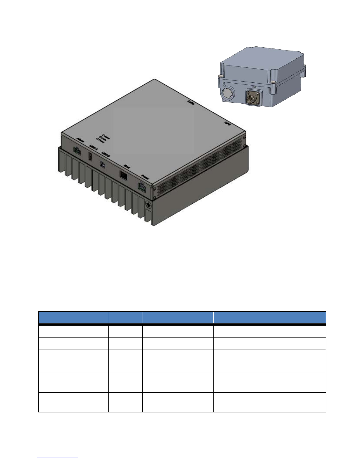
Figure 1 illustrates Mobile Gateway while Figure 2 illustrates the Fixed Gateway.
Figure 1: Pearl Mobile Gateway
Pearl Gateway User Manual T0004906 Version 1.6
TEKTELIC Communications Inc. Confidential Page 6 of 52
Interface
Location
Connector Type
Mating Connector
ISM Antenna Port
Front
TNC jack
Industry standard TNC plug
GPS Antenna Port
Front
TNC jack
Industry standard TNC plug
USB-A
Front
USB type A receptacle
Industry standard USB type A plug
USB-B
Front
USB type B receptacle
Industry standard USB type B plug
2-pin threaded circular
Shenzhen Chogori Technology Co., Ltd.
Industry standard single hole lug for #8-
TTU
Module
Fixed Gateway
Module
Figure 2: Pearl Fixed Gateway
1.3 External Interfaces
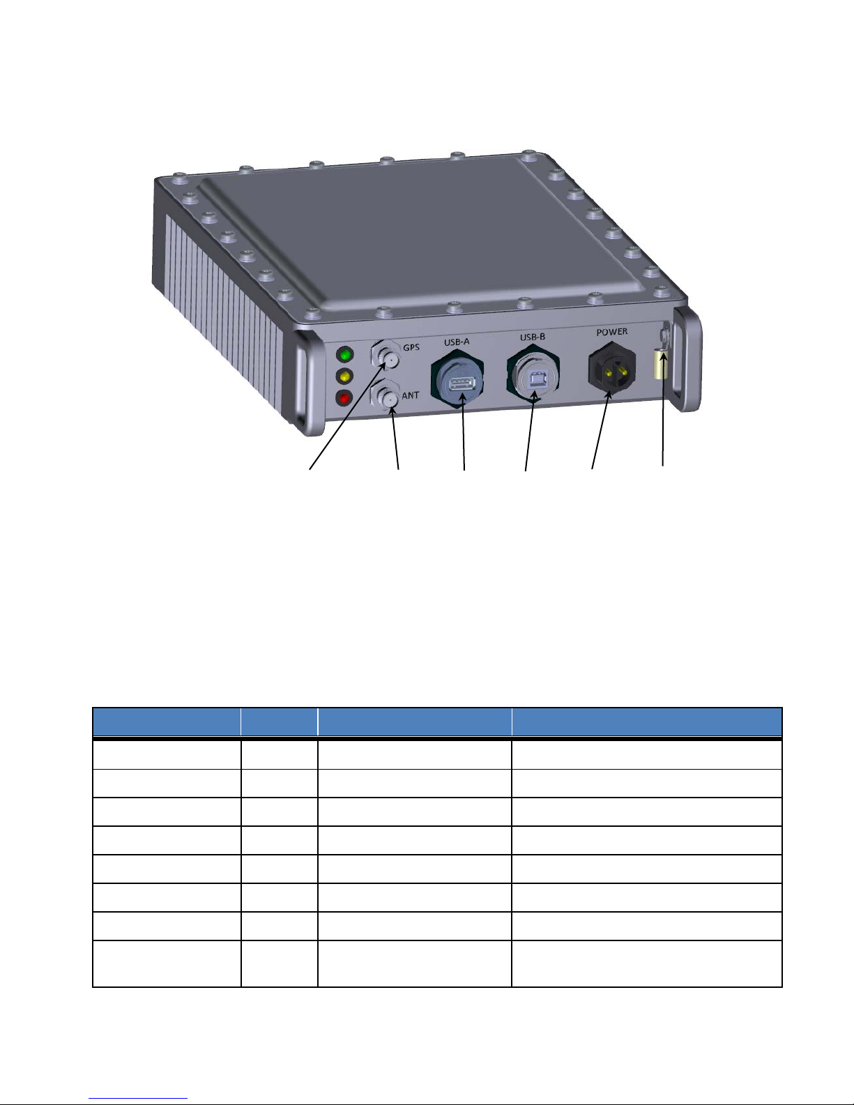
The Mobile Gateway Module interface connectors are listed in Table 1-2 and illustrated in
Figure 3.
Table 1-2: Pearl Mobile Gateway Module Interface Connectors
DC Power Front
Chassis (Earth) Ground
Pearl Gateway User Manual T0004906 Version 1.6
TEKTELIC Communications Inc. Confidential Page 7 of 52
Front Screw with lug
plastic connector ( CPC)
p/n 33000111-02 or equivalent
32 screw
Interface
Location
Connector Type
Mating Connector
TTU interface Port
Back
SMA jack
Industry standard SMA plug
GPS Antenna Port
Back
SMA jack
Industry standard SMA plug
DC Power & alarms
Front
Molex Mini-fit 2x3 header
Molex Mini-fit 2x3 plug
Site Alarms
Front
Molex Mini-fit 2x4 header
Molex Mini-fit 2x4 plug
USB-A
Front
USB type A receptacle
Industry standard USB type A plug
USB-B
Front
USB type B receptacle
Industry standard USB type B plug
Ethernet
Front
RJ-45 socket
Industry standard RJ-45 plug
Industry standard single hole lug for #8-
USB-B
DC power
USB-A
ISM antenna
Chassis
ground
GPS antenna
Figure 3: Pearl Mobile Gateway Module Interconnect
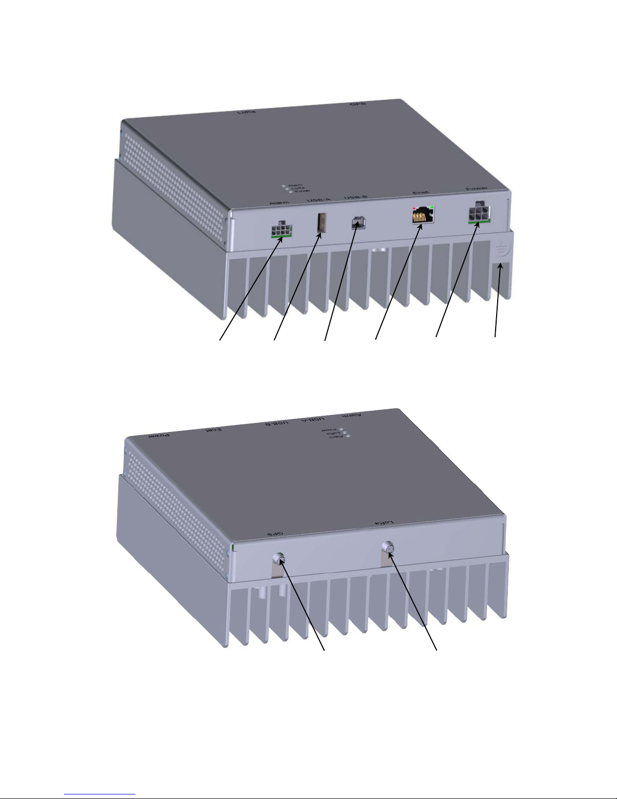
The Fixed Gateway Module interface connectors are listed in Table 1-3 and illustrated in Figure
4.
Table 1-3: Pearl Fixed Gateway Module Interface Connectors
Chassis (Earth)
Front Screw with lug
Ground
Pearl Gateway User Manual T0004906 Version 1.6
TEKTELIC Communications Inc. Confidential Page 8 of 52
32 screw
Site alarms
USB-B
DC power
& alarms
Ethernet
USB-A
GPS antenna
ISM antenna
Chassis
ground
Front Bulkhead
Rear Bulkhead
Figure 4: Pearl Fixed Gateway Module Interconnect
Pearl Gateway User Manual T0004906 Version 1.6
TEKTELIC Communications Inc. Confidential Page 9 of 52

Interface
Location
Connector Type
Mating Connector
ISM RF Antenna Port
Top
N-type female
Industry standard N-type male
Gateway module
Industry standard single hole lug for #8-
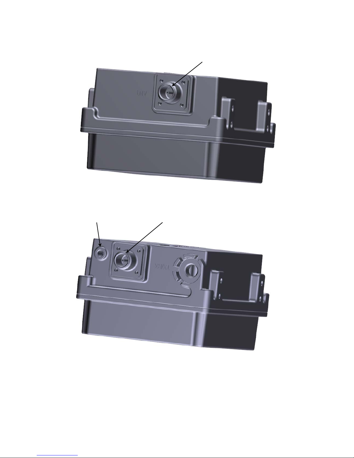
The TTU Module interface connectors are listed in Table 1-4 and illustrated in Figure 5.
Table 1-4: Pearl TTU Module Interface Connectors
interface Port
Chassis (Earth)
Ground
Bottom N-type female Industry standard N-type male
Bottom Screw with lug
32 screw
Pearl Gateway User Manual T0004906 Version 1.6
TEKTELIC Communications Inc. Confidential Page 10 of 52
Fixed Gateway
Chassis
IMS antenna
port
Top
Bottom
ground
Module interface
Figure 5: Pearl TTU Module Interconnect
Pearl Gateway User Manual T0004906 Version 1.6
TEKTELIC Communications Inc. Confidential Page 11 of 52

1.4 Specifications
Attribute
Specification
Dimensions
218.8mm (8.6”) wide x 72mm (2.8”) deep x 303.8mm (12.0”) tall
Weight
3.15 kg (6.95 lbs)
-40°C to 60°C (-40°F to 140°F) ambient at sea level Including solar loading
10% to 100%
Maximum 2,000 m (6,560 ft)
12V DC nominal
ISM antenna output
power
GPS antenna output
power
Indoor product
CSA/UL 60950-1
Attribute
Specification
Dimensions
189.4mm (7.5”) wide x 77mm (3.0”) deep x 197.8mm (7.8”) tall
Weight
1.71 kg (3.76 lbs)
-40°C to 70°C (-40°F to 158°F) ambient at sea level Including solar loading
10% to 100%
Maximum 2,000 m (6,560 ft)
12V DC nominal
+/-16V DC no damage
The Pearl Mobile Gateway Module specifications are listed in Table 1-5.
Table 1-5: Pearl Mobile Gateway Module Specifications
Operating Temperature
Relative Humidity
Operating Altitude
10V to 15V DC operating range
DC Power Input
+/-16V DC no damage
30W maximum
Maximum 20A input overcurrent protection.
5V DC, 300mA maximum
5V DC, 50mA maximum
Weather Tightness
Regulatory Compliance
FCC Pt. 15 Class B
The Pearl Fixed Gateway Module specifications are listed in Table 1-6.
Table 1-6: Pearl Fixed Gateway Module Specifications
Operating Temperature
Relative Humidity
Operating Altitude
DC Power Input
Pearl Gateway User Manual T0004906 Version 1.6
TEKTELIC Communications Inc. Confidential Page 12 of 52
10V to 15V DC operating range

40W maximum
TTU port output power
12V DC, 1.5A maximum
GPS antenna output
power
Indoor product
CSA/UL 60950-1
Attribute
Specification
Dimensions
222.2mm (8.7”) wide x 101mm (4.0”) deep x 287.3mm (11.3”) tall
Weight
2.1 kg (4.6 lbs)
-40°C to 65°C (-40°F to 149°F) at sea level Including solar loading.
10% to 100%
Maximum 3,048 m (10,000 ft)
20kV, 1.2/50us combination waveform
IP67
CSA/UL 60950-1 & & CSA/UL 60950-22
Weather Tightness
Maximum 20A input overcurrent protection.
5V DC, 50mA maximum
Regulatory Compliance
FCC Pt. 15 Class B
The Pearl TTU Module specifications are listed in Table 1-7.
Table 1-7: Pearl TTU Module Specifications
Operating Temperature
Relative Humidity
Operating Altitude
Surge protection
Weather Tightness
Regulatory Compliance
FCC Pt. 15 Class B
Pearl Gateway User Manual T0004906 Version 1.6
TEKTELIC Communications Inc. Confidential Page 13 of 52

This radio transmitter (Mobile Gateway IC: 22504-T0004437, Fixed Gateway IC: 22504-
Gateway
Antenna
Mobile
Fixed
Gateway +
Fixed
Gateway +
T0004438) has been approved by Industry Canada to operate with the antenna types listed
below with the maximum permissible gain indicated. Antenna types not included in this list,
having a gain greater than the maximum gain indicated for that type, are strictly prohibited for
use with this device.
The specified ISM antennas are listed in Table 1-8. Antenna types not included in Table 1-8,
having a gain greater than the maximum gain indicated for that type, are strictly prohibited for
use with this device.
Table 1-8 ISM Antennas
Type
Gateway
TTU
TTU
IC: Number
IC: 22504-T0004437 PCTel BMUF9115 5
IC: 22504-T0004438 L-Com HG908U-PRO 8
IC: 22504-T0004438 L-Com HGV906U 6
Vendor
Model Number Gain (dBi)
Pearl Gateway User Manual T0004906 Version 1.6
TEKTELIC Communications Inc. Confidential Page 14 of 52

2 Installation
2.1 Safety Precautions
• Installation, operation, and maintenance of the Pearl Gateway must only be performed by a
trained person who is aware of all hazards involved.
• The Pearl Gateway must be installed in a restricted access location (such that touching of
the Gateway by untrained persons is not likely).
• The Pearl Gateway may become hot to the touch during normal operation at elevated
ambient temperatures. The surface temperature of the enclosure may reach 90°C.
• The Pearl Gateway has no internal field serviceable parts. The Gateway module must only
be opened by an approved service center.
• All installation practices must be in accordance with local and national electrical codes.
• Do not work on the system during periods of lightning activity.
• The Pearl Gateway is considered permanently connected equipment. The Protective Earth
Ground connection to chassis is always required.
• Ensure the Pearl Gateway Protective Earth Ground connection is properly terminated prior
to the connection of any other interfaces.
• The Pearl Gateway TTU contains primary lightning surge suppression on the RF ports. The
primary lightning protectors have the ability to shunt lightning energy to earth ground
which includes the chassis. Ensure that the Protective Earth Ground connection is always in
place.
• Ensure that the Pearl Gateway including the TTU and its antennas and supporting structures
are properly secured to eliminate any physical hazard to people or property. The Gateway
including the TTU must be securely mounted according to the mounting instructions prior to
any cable connection and operation.
• The Pearl Gateway does not contain a power supply disconnection device; a readily
accessible disconnection device must be incorporated external to the Gateway.
• The Pearl Gateway shall be supplied through an input overcurrent protection device rated
not more than 20 A. The overcurrent protection must have the appropriate current
interrupt capacity for the power source and must be incorporated into the non-earthed
conductor(s) of the DC supply.
Pearl Gateway User Manual T0004906 Version 1.6
TEKTELIC Communications Inc. Confidential Page 15 of 52

• The DC input power positive pin must be at positive potential relative to the DC negative pin
for the Gateway to function. If the polarity is reversed, the unit will not sustain damage but
will not operate until the polarity is corrected.
• The Pearl Gateway DC power source must meet SELV requirements.
2.2 Unpacking and Inspection
The following should be considered during the unpacking of a new Pearl Gateway.
1. Inspect the shipping carton and report any significant damage to TEKTELIC.
2. Unpacking should be conducted in a clean and dry location when possible.
3. Do not discard the shipping box or foam inserts as they will be required if a unit is
returned for repair or re-configuration.
2.3 Required Equipment for Installation
The following tools are required to install the Pearl Gateway system:
1. An imperial and a metric socket with Torx set and a torque wrench.
2. Anti-oxidant compound (NO-OX-ID, Penetrox, Noalox, Ox-Gard or equivalent).
3. A small wire brush or emery cloth.
4. A clean cloth.
5. Weatherproofing tape kit for the RF connectors (Scotch Wireless Weatherproofing Kit,
WK-101 recommended).
6. Four M4 screws with locking hardware for Gateway mounting (length according to
application, see next section).
7. Four M8 screws with locking hardware for TTU mounting according to application (see
next section).
2.4 Pearl Gateway Mounting
The Pearl Gateway Modules are designed to be mounted to a flat surface using site supplied
M4 x 0.7 stainless screws with locking hardware, one at each of the four mounting points as
illustrated in Figure 6 for the Mobile Gateway Module and Figure 7 for the Fixed Gateway
Module. These four mounting screws are to pass through pre-drilled holes in the mounting
surface. The mounting drill-hole pattern is on a square as indicated in Figure 6 and Figure 7. The
dill size shall be selected for a slight clearance to M4 screws.
Mounting the Gateway module requires access to both sides of the mounting surface; this may
require two persons in cases where the mounting surface is large.
Pearl Gateway User Manual T0004906 Version 1.6
TEKTELIC Communications Inc. Confidential Page 16 of 52
 Loading...