

Page 1
TCG 01
TIME CODE GENERATOR
User Manual
9thEdition
Page 2

www.tekroninternational.com
Page 2 of 49
Page 3

TCG-01
Revision History:
Time Code Generator
User Manual
9thEdition
February 2007
This document supports all TCG-01 with firmware revision D1—D8
R
R4 For 0, A-B TCG-01
R5 For 0, A-B and C4-C7 TCG-01
R6 All C and D up to D1 version TCG-01
R7 All C and D up to D1 version TCG-01
R8 All C and D up to D4 version TCG-01
R9 (This document) For D up to and including D8 version TCG-01
Page 4

www.tekroninternational.com
TABLE OF CONTENTS
1 INTRODUCTION....................................................................................................1
2 INSTALLATION ......................................................................................................2
2.1 Packing list..................................................................................................................................... 2
2.2 Mounting ....................................................................................................................................... 2
3 OPERATION ............................................................................................................3
4 FRONT PANEL........................................................................................................3
4.1 LCD Display ................................................................................................................................... 4
4.2 Front Panel LED Indicators: ...................................................................................................... 6
5 CONNECTIONS......................................................................................................7
5.1 P1: Power Input ............................................................................................................... ........... 7
5.2 Ant: Antenna connector (SMA plug)..................................................................................... 7
5.3 P2, P3: Outputs............................................................................................................................. 8
5.4 P4: RS232 I/O (Serial port plus programmable output) ................................................ 9
5.5 Earth stud.....................................................................................................................................10
5.6 P5: BNC output .........................................................................................................................10
5.7 P6: Event Recording Inputs or External Sync Input........................................................ 11
5.8 P7: Sync Relay .............................................................................................................................11
5.9 P8: NTS – network time-server (optional)......................................................................... 12
6 SPECIFICATIONS .................................................................................................13
6.1 Dimensions ..................................................................................................................................13
6.2 Identification............................................................................................................................... 13
6.3 Programmable outputs (P2, P3, P4-pin1) .........................................................................13
6.4 Isolation & Protection ..............................................................................................................14
7 FACTORY HARDWARE OPTIONS...................................................................15
7.1 TCG 01 High Voltage Output Option .................................................................................15
7.2 Power Supply Options .............................................................................................................16
7.3 Lightning Protection Option ................................................................................................. 16
7.4 Multi-port Hub Option............................................................................................................ 16
8 TCG 01 CONFIGURATION SOFTWARE.........................................................17
8.1 Introduction ................................................................................................................................17
8.2 Local Time Settings...................................................................................................................18
8.3 General Options .........................................................................................................................18
8.4 Programmable Outputs........................................................................................................... 20
8.5 IRIG-B Options ........................................................................................................................... 22
Page 5

TCG 01 User Manual
9thEdition: February 2007
8.6 Local/UTC Selection ................................................................................................................. 22
8.7 Network Time Server Configuration................................................................................... 23
8.8 Visible Satellites......................................................................................................................... 23
APPENDIX A ANTENNA DETAILS ........................................................................25
A.1 Antenna Cable Specification ................................................................................................. 25
A.2 Antenna Specification ............................................................................................................. 26
A.3 Antenna Assembly .................................................................................................................... 26
APPENDIX B LIGHTNING PROTECTION OPTION ...........................................28
B.1 General ......................................................................................................................................... 28
B.2 LPK01 Kit Contents ................................................................................................................... 28
B.3 Installation................................................................................................................................... 29
B.4 Disclaimer .................................................................................................................................... 31
APPENDIX C EVENT TIME-TAGGING OPTION ................................................32
C.1 Introduction................................................................................................................................ 32
C.2 TCG 01 Command / Response Message structure ......................................................... 33
C.3 TCG 01 Commands related to Event Time Tagging ...................................................... 33
APPENDIX D NETWORK TIME SERVER OPTION .............................................36
D.1 Configuration Requirements................................................................................................. 36
D.2 Methods for Accessing Set-Up Mode ................................................................................ 36
D.3 Using Telnet to access Set-Up Mode.................................................................................. 37
D.4 NTS Set-Up Mode Menu ........................................................................................................ 38
D.5 Time Server Operation ............................................................................................................ 40
APPENDIX E SERIAL OUTPUT STRINGS.............................................................42
E.1 NGTS Time Code O/P on P4.................................................................................................. 42
E.2 IRIG J-17 Time Code O/P on P4 ........................................................................................... 42
E.3 String-A Time Code O/P on P4 ............................................................................................ 43
E.4 String-B Time Code O/P on P4............................................................................................. 43
E.5 String-C Time Code O/P on P4............................................................................................. 44
E.6 String-D Time Code O/P on P4 ............................................................................................ 44
E.7 String-E Time Code O/P on P4 ............................................................................................. 45
E.8 String-F Time Code O/P on P4 ............................................................................................. 45
E.9 NMEA ZDA Time Code O/P on P4....................................................................................... 46
E.10 NMEA RMC Time Code O/P on P4...................................................................................... 47
WARRANTY STATEMENT..........................................................................................48
Page 6

Page 7
TCG 01 User Manual
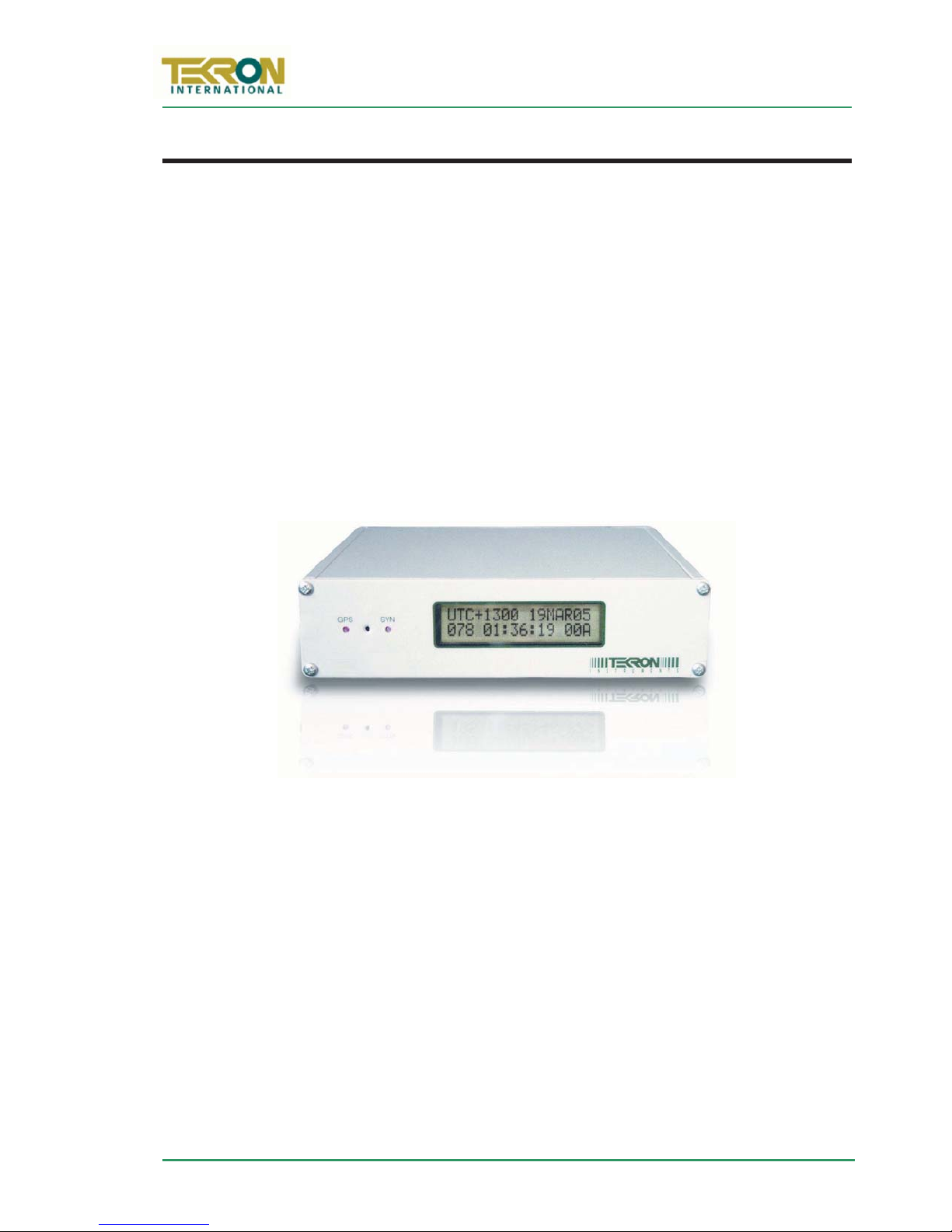
Figure 1 – TCG-01 Front Panel
9thEdition: February 2007
1INTRODUCTION
TCG 01 Time Code Generators produce precision time code signals, serial strings and
pulses for use in synchronising industrial control and SCADA equipment. They are ideally
suited to providing time synchronisation simultaneously to many different devices, such
as Remote telemetry Units (RTUs), Protection Relays and other Intelligent Electronic
Devices (IEDs) used in electrical sub-stations and industrial control installations.
The TCG 01 features one AM Modulated IRIG-B output, three programmable outputs
and a serial port which is user-configurable to output serial strings and report events for
units fitted with event recording capability. Factory options include an embedded
Network Time Server, and a choice of output connectors: BNC, 2-pin plug, or ST Fibre.
Non-fibre outputs that can be ordered are TTL, RS422, or high voltage switching.
All TCG 01 units feature a front panel display, giving visual feedback about the time data
being generated on the outputs. LED indicators provide “at a glance” status information.
The optimised receiver/antenna system used by TCG 01 obtains time with similar to
atomic clock precision from the GPS satellite constellation. The result is output timing
accuracy similar to that normally seen only in laboratory instruments.
However, unlike laboratory instruments, TCG 01 is suited for hostile electromagnetic
environments such as sub-stations and electrical switchyards. Each output of the TCG 01
is isolated from every other output, so that attached wiring can feed out to operating
areas in different earth potential zones without compromising the overall site earthing
security. Further isolation protects the internal electronics, and transient suppression
devices protect i/o from both longitudinal and transverse high voltage events.
TCG-01 occupies less than half the width of a 1U rack space. It is supplied complete with
all hardware and software required for installation, including rack-mount kit, connectors,
30m lead-in antenna cable, and antenna.
F
Page 1 of 49
Page 8

www.tekroninternational.com
GPS Antenna:
2INSTALLATION
2.1 Packing list
Each TCG 01 kit is shipped with the following:
x TCG 01 Time code generator
x User Manual – this document
x GPS Antenna optimised for stationary applications, with pedestal for pipe mount
x Antenna lead-in cable fitted with matching connectors
x 19” Rack mounting Plate & fasteners
x Matching plug-in connectors
x RS232 Interface cable
x Configuration Software
2.2 Mounting
The clock is designed to be mounted in a 19” rack, but may be used on a bench. The
unit is attached to the rack mount plate via the four screws shipped installed in the four
corners of the front panel.
G
page 25. The antenna should be located in a position with as clear a view of the sky as
possible, over as wide an angle as possible.
“lightning-protected zone” as far as is possible.
there is at least one other earth-bonded structure located in the same rooftop area (e.g.
another antenna, or a lightning rod) that reaches significantly higher than the top of the
GPS antenna. The GPS Antenna should be mounted so that it lies within a 45-degree
angle “skirt” from the top of the other earth-bonded structure. The GPS antenna mount
itself should also be securely bonded directly to the building protection earth – and
connected via any of the other earthed structures.
A lightning protection kit is available for installation in the antenna lead-in cable for
additional protection of the equipment. (See section 7.3 on page 16 for details.)
All TCG 01 antenna installations should follow the guidelines above.
Detailed antenna mounting instructions are contained in Appendix A on
The antenna should also be mounted in a
In practice, this means ensuring that
not
Page 2 of 49
Page 9

TCG 01 User Manual
P1
Figure 2 – TCG 01 Front Panel
LCD DISPLAY:
SYN LED:
GPS LED:
9thEdition: February 2007
3OPERATION
Connect the antenna lead and the antenna (with a good view of the sky). Then connect
the power source to P
Check the label on the base for voltage requirements before switching on!
The time required that will achieve tracking and synchronisation given a good “view” of
the sky is typically within a minute. Although reactivating a unit that was previously
synchronised 1000’s of km away from the present position will take longer but not more
than 45 minutes.
.
4FRONT PANEL
TCG01featurestwoLEDindicatorsonthefront panel, together with a 2-line by 16character LCD display. The display is optimised for viewing straight on, or from below, as
the clock is a lightweight device, normally mounted at eye level or higher in an
equipment bay.
The display unit updates every second, displaying day, date, time, and time
offset from UTC. It also provides more information on the GPS receiver
operation. A recessed push-button located on the front panel between the
two indicator LED’s is used to switch between display pages.
This LED operates in parallel with the Sync Relay, and is active at all times
when the unit is operating with time code outputs accurately tracking the
GPS time signals.
Flashing cadences indicate the status of the GPS receiver.
Page 3 of 49
Page 10

www.tekroninternational.com
Figure 3 – LCD display screens
4.1 LCD Display
The LCD display shows a copyright message, along with the serial number and revision
level of the unit for approximately 10 seconds following power-up, (Figure 3[a]). The
display then automatically changes to the operating default, (Figure 3[b]). The user may
cycle between all four of the screens by pushing the recessed pushbutton on the front
panel between the LED indicators. The display examples below all show the same instant
in time.
TEKRON TCG01-D:0
(C)2003 Sn02749
UTC+1200 17MAR03
076 11:16:53 87A
[a] Start Up (Clock ID) [b] Operating Default
LST:MON 17 MAR03
076 11:16:53 87A
UTC:SUN 16 MAR03
075 23:16:53 87A
[c] Local Time [d] UTC Time
F
The top line of screen [b] shows the UTC offset in hours and minutes and the local date.
The local day-of-year and time-of-day are on the bottom line.
The rightmost bottom three characters provide satellite tracking information. “UTC”
denotes UTC time (similar to GMT) while “LST” denotes Local Standard Time. If daylight
savings time is active, “LST” in screen [c] changes to “LDT”, denoting Local Daylight Time.
Screen [b] shows that the clock is operating with a local time offset of 12 hours ahead of
UTC. The local date is 17
th
March 2003, and the local time is 11:16:53 in the morning.
Screen [c] shows the same time and date, but also indicates that the time displayed is
Local Standard Time, and that the day is Monday.
Screen [d] shows the UTC time and date, which is 11:16:53 on the evening of Sunday 16
March 2003.
Page 4 of 49
Page 11

4.1.1 Satellite Tracking Status
LST:MON 17 MAR03
076 11:16:53 87A
Satellites in sky
Satellites tracked
Receiver status
Character Values Description
TCG 01 User Manual
9thEdition: February 2007
Display screens Figure 3: [b], [c] and
[d] all show a three-character status
field at the bottom right-hand side
of the display. This three-character
field provides feedback on the
parameters that affect the operation
of the GPS receiver.
Satellites
in sky
Satellites
Tracked
Receiver
status
“0”=0
“9”=9
“A”=10
“B”=11
“C”=12
“0”=0
“9”=9
“A”=10
“B”=11
“C”=12
Represents the total number of satellites currently present in the
:
sky according to the GPS almanac. “0” in this position means that
TCG 01 has lost its knowledge of the GPS satellites’ orbit
geometries. This occurs if the unit has been in storage for an
extended period, or if the GPS receiver has been reset. It may
take up to two hours for the TCG 01 to operate normally again.
This digit represents the number of satellites currently being
:
used to compute the time solution. A “0” value means that no
updated time solution is available, (“out of lock” condition). If
this condition persists for the “Sync Hold” time (See |section 8.3.1
on page 18) the clock will indicate the “out of sync” condition
described under section 4.2.1 Warning Status Indications below.
“A” TCG 01 in Acquisition mode --attempting to get satellite fixes
“G” “Poor satellite geometry”: Satellites are positioned in almost a
straight line so best accuracy cannot be obtained, but the unit
willstillsynctoUTC.
“2” A 2D position is in use (no height). This may occur before
“3” A 3D position is in use, which includes height. A site survey
“S” Site Survey in progress. TCG-01 is calculating an accurate
“P” “Position hold”: Position is known accurately, and the GPS is
Position Hold mode has been reached if only 3 satellites are
tracked. Synchronisation is not compromised.
begins next, so this mode is rarely seen.
position; once complete the mode will change to Position hold.
providing its most accurate time, better than 60ns to UTC.
Page 5 of 49
Page 12

www.tekroninternational.com
4.2 Front Panel LED Indicators:
The GPS LED shows the status of the GPS receiver, while the SYN LED shows the status
of the time synchronisation to UTC reference time derived from the GPS satellites.
By default, all outputs become active within a few seconds of initial power-up
even when the unit is
precise until the unit is synced to the GPS satellite
4.2.1 Warning Status Indications (SYN LED = OFF)
When the SYN LED is off, TCG-01 is not guaranteed to be synchronised to UTC time. The
sync relay is deactivated (“C” is connected to “NC”).
GPS LED SYN LED Interpretation
not
synced to GPS satellite time! Output time data is not
•••• ••••
OFF Antenna fault: The GPS antenna is not connected,
4 short flashes/second
•• •• •• ••
or is short or open circuited (faulty).
OFF The GPS antenna is good, and the unit is
2 short flashes/second
searching the sky for satellites to begin the sync
process.
On D4 and later version TCG-01s, a “test mode” is available that when activated
will cause all TCG-01 outputs including the sync relay to behave as if they are in
sync, even if they are not. This can be useful for testing the operation of external
IED when a connection to a GPS antenna is not available.
4.2.2 Sync Status Indications (SYN LED = illuminated)
When the SYN LED is on, TCG-01 is synchronised to UTC time. All of the clock outputs
are accurate and are usable for sync purposes and the sync relay output is activated.
GPS LED SYN LED Interpretation
••••••••••••••••••••••••••••••••••••••••••••••••••••••••
ON Time accuracy is within 500ns of UTC time.
Long on – short off
once every second
••••••••••••••
ON Time accuracy is certainly within 60ns and is typically
Short on – long off
once every second
Page 6 of 49
within 40ns of UTC time
Page 13
TCG 01 User Manual
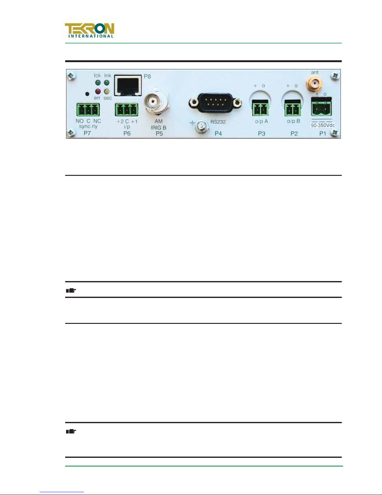
Figure 4 – Rear Panel of TCG 01, with 2-pin connectors (P2 and P3) and NTS output (P8)
9thEdition: February 2007
5CONNECTIONS
F
5.1 P1: Power Input
Power is applied to the unit via this plug. Maximum steady state power consumption is
6W, and surge protection is provided. Despite the markings on P1, the polarity of the
power connection is
power source. A mating connector is supplied that is suitable for wiring up to 1.5mm
not
important and the unit is fully isolated internally from the
2
.
The casing is isolated from the power supply inputs so that either (or neither) power
supply polarity can be earthed to station earth.
The input voltage range is marked on the option label that is attached to the underside
of TCG-01. The section Power Supply Options on page 16 has a list of orderable ranges.
Check the label on the unit base for power supply voltage ratings!
5.2 Ant: Antenna connector (SMA plug)
The “ant” antenna input provides an interface for an external active antenna via low-loss
coaxial cable, 50ȍ impedance. 5V DC @ 50mA max is supplied to power an active
antenna. The total combined gain of the antenna system (antenna plus cable and
connectors) should fall in the range of 10 to 35 dB, the optimum being 22dB.
TCG 01 is normally supplied complete with a timing-optimised narrow-band antenna
and 30m of lead-in cable, this combination provides an overall gain near the optimum
of 22dB (see Appendix A on page 25). For lead-in lengths longer than 60m, either
amplification and/or larger diameter, lower loss cable can be supplied to order.
Care should be taken to ensure that the connector is not cross-threaded when
attaching the antenna lead-in cable. The connector should be tightened firmly
by hand only. Do NOT over-tighten!
Page 7 of 49
Page 14
www.tekroninternational.com
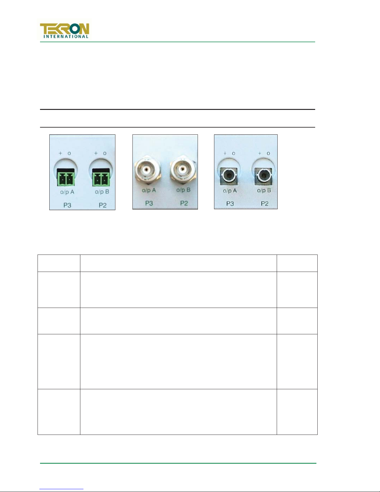
Figure 5 – 2pin
connectors
Figure 6 – BNC
connectors
Figure 7 – Fibre
connectors
A Lightning Protection device may be inserted into the antenna lead. A suitable device
complete with additional cable connectors, a connector crimping tool and mounting
hardware is available as an option (see Section 7.3 on page 16). Introduction of the
Lightning protector does not degrade the performance of the antenna system.
5.3 P2, P3: Outputs
5.3.1 Electrical and Physical Configuration
F
Each output port may be fitted at the factory according to the following:
Electrical Electrical Specification Physical
TTL CMOS/TTL (5V) logic level driver output ports, 150mA sink
and source. The port is fully floating and has independent
electrical isolation to 2.5kV
RS422 High Speed RS422 compliant output ports. The port is Fully
floating and has independent electrical isolation to 2.5kV.
HV
MOSFET
Fibre ST fibre transmitters, compatible with ST-terminated 62.5ȝm
Power MOSFET Switch, allowing switching of 300VA, 1A max.
The port is fully floating and had independent electrical
isolation to 2.5kV. See the detail in Section 7.1 on page 15 for
suggested wiring configurations for use with Power MOSFET
switching.
fibre diameter, 125ȝm jacket diameter multi-mode fibre optic
cabling. The maximum length of fibre recommended is 700
metres.
2-pin
or BNC
2-pin
or BNC
2-pin
ST Fibre
Page 8 of 49
Page 15
TCG 01 User Manual
pin 2
pin 3
pin 5
pin 1
pin 5
9thEdition: February 2007
5.3.2 P2, P2 programmable signals
The user may configure P2 and P2 to output in either inverted or non-inverted polarity:
x A user configurable number of pulses per second, minute, hour, day with
adjustable pulse-width and offset.
x IRIG-B and DCF-77 time codes.
Refer to page 13 for further information:
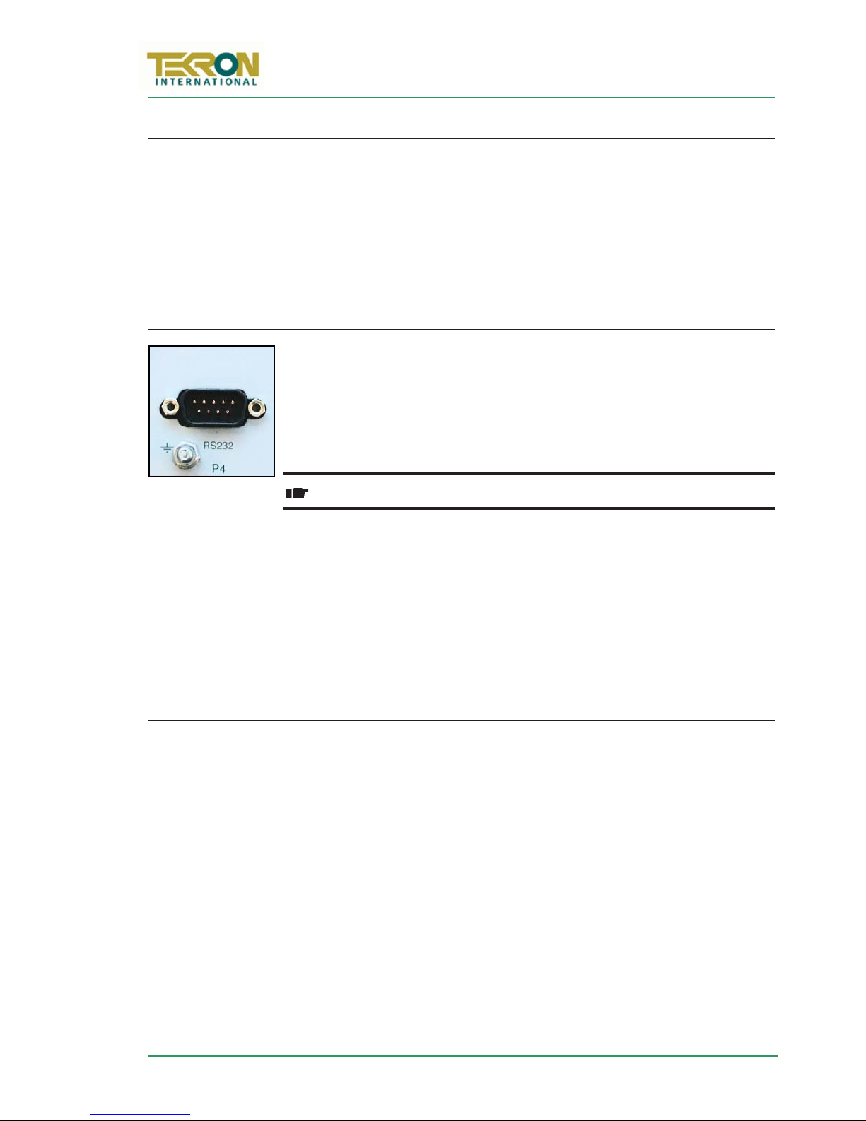
5.4 P4: RS232 I/O (Serial port plus programmable output)
An RS232 port (+/-9V signal levels) is implemented via 9-way “D”
male connector with signal lines: p
01), p
(serial data IN to TCG 01) and p
together with a programmable signal output on p
programmable output shares the p
(serial data OUT from TCG
(signal ground)
(signal ground).
.The
Do NOT over-tighten the securing screws of the connector!
TCG 01 is normally shipped as a DCE configuration, a “straight-wired” Socket-to-Socket
9-way data cable can be used to connect directly to a standard PC serial port. (A suitable
2m cable is included with each TCG 01/TCG 01F.) The CTS and DSR functions are
permanently asserted, so the serial port does not support hardware handshake control.
The RS232 signal lines are not HV-isolated from each other, but the port as a whole is
isolated to a level of 2.5kV from all other ports.
5.4.1 P4 serial strings
The serial port can be configured to output any one of a number of different serial time
messages on a broadcast basis. The serial port runs at a fixed baud-rate of 9600 baud.
Message formats typically operate at 8-bit no parity, no flow control, 1 stop bit, and are
transmitted once per second.
A wide range of message strings, and protocols are output on this port. They include:
x NGTS protocol
x IRIG J-17
x Six preset messages, String/Tekron A—F for compatibility with most IED.
x In TCG 01 version D8 and later, NMEA ZDA and RMC messages are available.
x GPS Binary/Messages, these are subject to change without notice.
See |Appendix E on page 42 for details of each of the message string formats.
Page 9 of 49
Page 16
www.tekroninternational.com
5.4.2 P4 pin 1 Programmable Output
The user may configure P4 pin 1 to output in with inverted or non inverted polarity:
x A user configurable number of pulses per second, minute, hour, day with
adjustable pulse-width and offset.
x IRIG-B and DCF-77 time codes.
Refer to section 6.3 on page 13 for further information:
5.5 Earth stud
An M4 bolt (to chassis) is provided for earthing of cable shields. This
is located under the serial port to the left of the P4 designator.
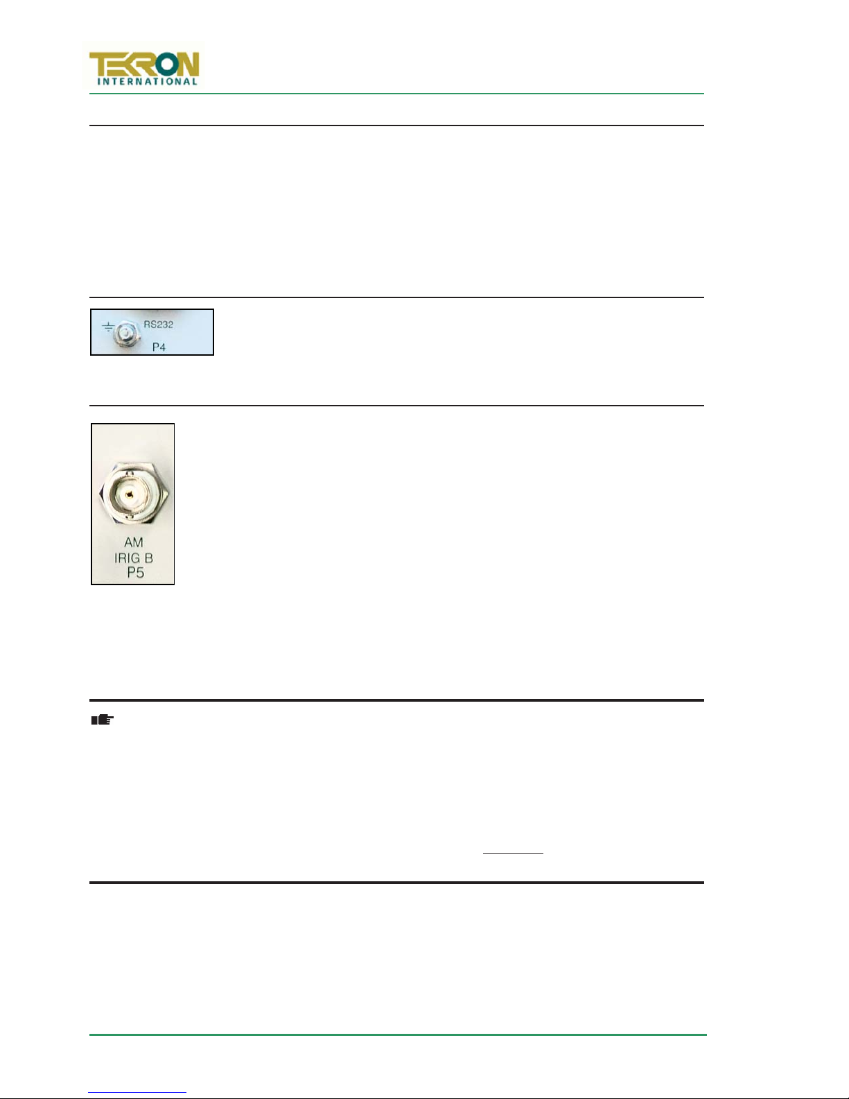
5.6 P5: BNC output
P5 provides amplitude modulated IRIG-B (B12x) over a BNC connector.
Use either coaxial cable or shielded twisted pair, to feed signal from P5 to
any connected IED. When using shielded twisted pair, connect the shield
to ground.
The mark/space amplitude modulation ratio is 10:3, and peak to peak
output level is 8 volts (max), 100: impedance. The output is fully floating,
and is transformer-isolated to a minimum of 2.5kV.
not
This output is
present whenever the unit is powered. The particular IRIG-B data content is as specified
by the configuration program (refer to IRIG-B Options on page 22).
Most devices with amplitude-modulated IRIG-B time sync inputs have an input
impedance of between 4k: and 20k:, and maximum allowable peak- to-peak
level of 6V or so. The P5 o utput on TCG 01 is designed to drive many of these
devices all in parallel, with a terminating resistor (typically 100-180 ohms) fitted
at the far end of the coax line feeding all of the attached loads. In this way P5
can drive at least 20, and typically 30 or more devices without any external
amplification required. The terminating resistor is essential to ensure good noise
immunity.
programmable for other types of signal, and the IRIG-B code is
Page 10 of 49
Page 17
TCG 01 User Manual
9thEdition: February 2007
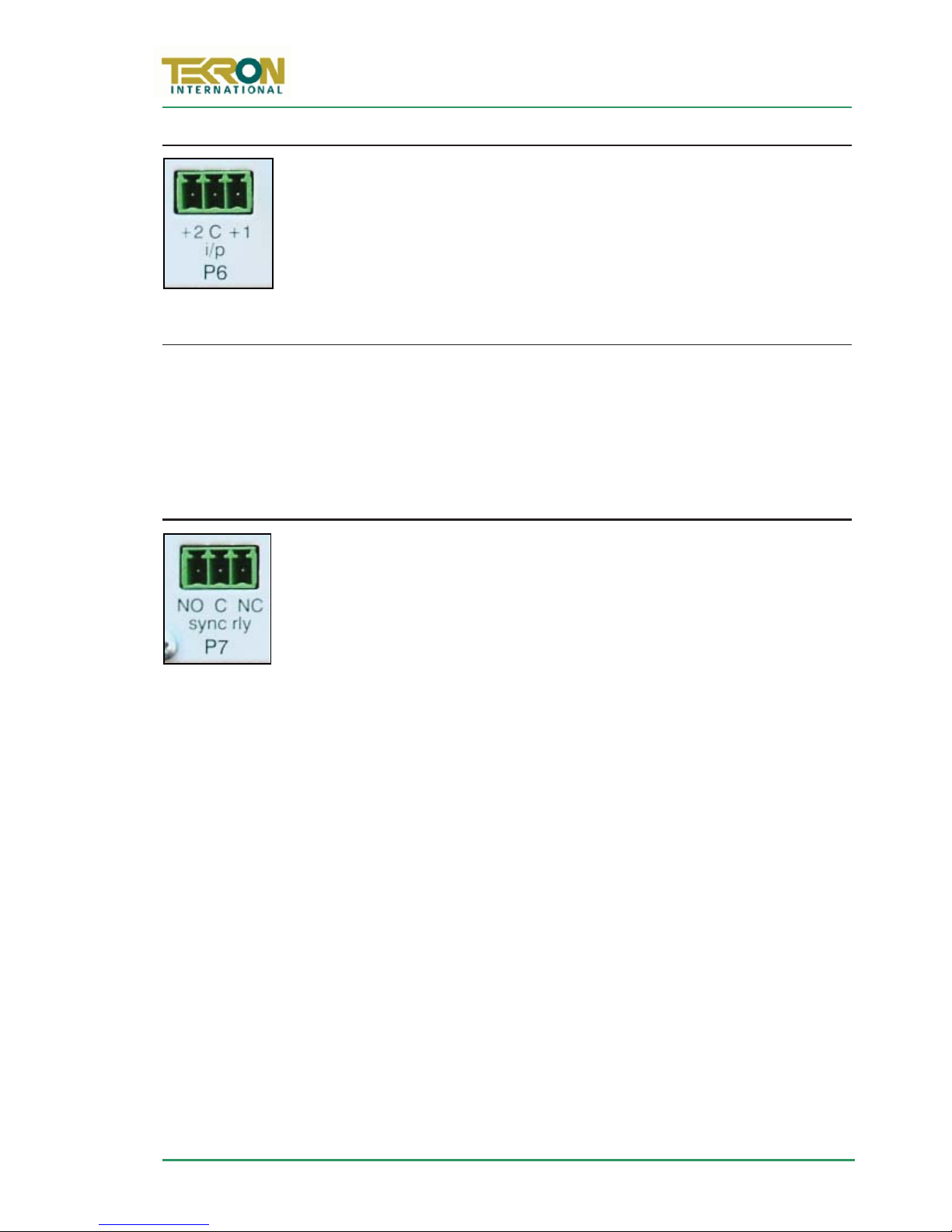
5.7 P6: Event Recording Inputs or External Sync Input
Two input channels with common return that may be driven by TTL logic
levels. This port is implemented via a 2-pin plug-able connector. Wiring
2
size is up to 1.0mm
“C” is the common reference (0V), and “+2” and “+1” are TTL inputs 2
and 1 respectively. Input burden is 7mA at 5V.
P6 is used for:
x Event time tagging or “event recording” on units with this option fitted. For a full
description, see Appendix C on page 32.
x Synchronisation of TCG 01 to an external IRIG-B signal, only in D4 or later
firmware. See Section 8.3.7 Sync to IRIG-B Input on page 20 for further
information on using this feature.
5.8 P7: Sync Relay
and the input is isolated to 2.5kV.
A set of isolated changeover relay output via 3-pin plug-able connector
– capable of switching up to 2A at 230V AC, or 300mA at 150V DC.
2
Wiring size is to 1.0mm
using the supplied mating plug. Isolation is
2.5kV minimum.
This relay is active (“C” and “NO” connected) whenever the TCG 01 has
established stable time sync from the GPS satellites. The active relay output indicates
that all of the other output signals are operating within specification. The connector
2
accommodates 1mm
cabling.
TCG 01 will remain accurate for a time after the loss of satellite sync, and the sync relay
can be configured to remain active (indicating “in sync”) for a period following the loss
of satellite signals. The default period is one minute, but this can be altered up to a
maximum period of 42 minutes and 30 seconds (2550 seconds).
Page 11 of 49
Page 18
www.tekroninternational.com
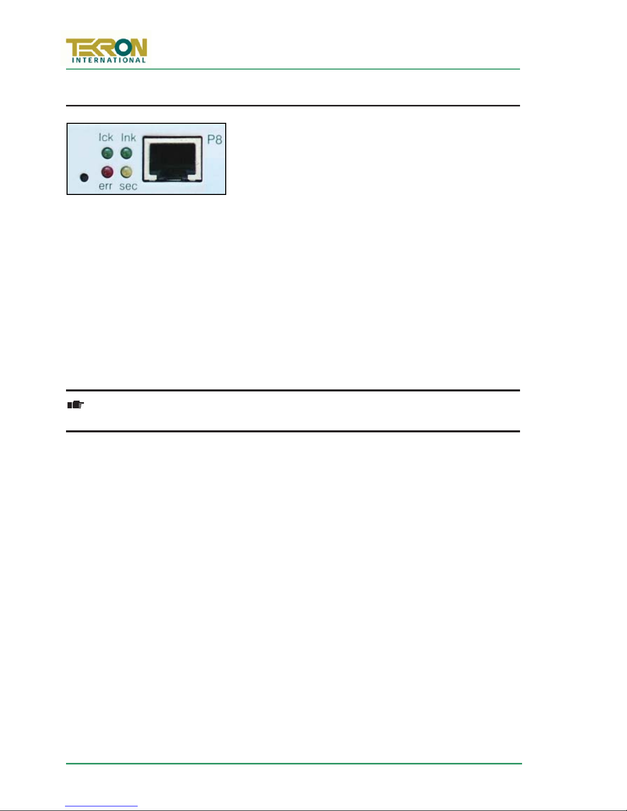
5.9 P8: NTS – network time-server (optional)
TCG 01 units fitted with the network time-server option
(NTS), feature an RJ45 connector supporting a 10Mbps
Ethernet port (10baseT). A standard (i.e. non-crossover)
drop lead should be used to connect the TCG 01 to a
convenient port on a local network hub or switch.
Protocols supported by the TCG 01 NTS option are: ARP, UDP, TCP, ICMP, Telnet, TFTP,
DHCP, SNMP and BOOTP. A TCG 01 unit equipped with the NTS option provides a
complete Stratum-1 time-server function while still retaining all other output services.
Specific time-sync client protocols supported are NTP and SNTP. SNMP trap support
allows for status monitoring and NTS alarm reporting to 3rd party network management
packages. Status reporting can be integrated with existing network management
software to provide a complete package.
Provision is made for up to 5 different IP addresses to be specified for SNMP trap
destinations, as well as two “Syslog” IP addresses. Accuracy of the NTS time stamps
produced is to within 1milliSec of UTC.
The RJ45 UTP port is
the standard balanced nature of a UTP connection for an office network
Each TCG 01 unit equipped with the NTS option is supplied complete with a 2M UTP
cable. This cable is designed to connect directly between the TCG 01 unit and a network
hub/switch/router. The cable is not suitable for direct connection to the network port on
a PC. If such a connection is required, a cross-over cable must be obtained.
The NTS is configurable using the supplied configuration tool and a serial cable, or via a
password protected telnet connection. Appendix D on page 36 contains detail about
how to install and configure the network time server option.
not
HV-isolated from the TCG 01 chassis, but complies with
Page 12 of 49
Page 19

TCG 01 User Manual
pin 1
pin 5
9thEdition: February 2007
6SPECIFICATIONS
6.1 Dimensions
Width 160mm
Depth 155mm
Height 40mm (1U)
Weight 0.8Kg
Each TCG 01 unit is supplied complete with antenna, antenna mount, antenna cable and
1U 19” rack-mount hardware. Shipping weight of the complete TCG 01 kit is 4.5Kg.
6.2 Identification
Each TCG 01 unit is shipped with an identification label on the base. The label provides
details of the particular options fitted to the unit, the power supply requirement, and the
serial number.
6.3 Programmable outputs (P2, P3, P4-pin1)
The outputs P2, P3, and P4-pin1 are each independently programmable to provide one
of the following options.
x DCF-77 pulse simulation
x Unmodulated (i.e. DC level-shift) IRIG-B (B00x)
x Modified Manchester Modulated IRIG-B (B22x)
x Programmed pulse sequence
In the case of “Programmed pulse sequence” above, separate settings are provided so
that a differently programmed pulse sequence can be specified for each of the three
outputs. Each of the three programmable outputs can also be inverted in its operation.
Full details on configuring the programmable outputs are contained in section 6.1 on
page 13.
N.B: P4-pin1 is not available on TCG 01's with DTE serial ports. If not specified,
TCG 01 will ship with a DCE serial port.
A common application for the programmable output on P4-pin1 (RS232 level) is to
provide an independent drive to an RS232-Fibre converter unit for use in transporting
the code signals to a distant location. In such cases, p
normal 9-way cable optionally used to connect to an external PC, and used in
conjunction with p
(MOFR’s) that includes such converters.
(signal return). Tekron manufactures a range of interface devices
should be “broken out” of the
Page 13 of 49
Page 20
www.tekroninternational.com
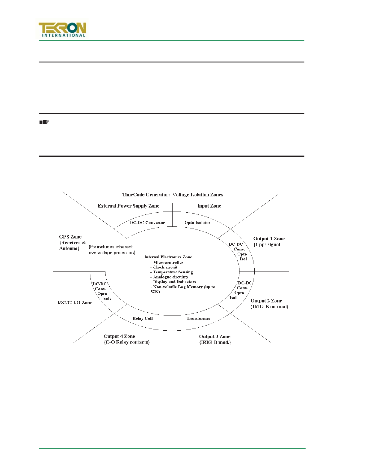
Figure 8 – TCG 01 Isolation Zones
6.4 Isolation & Protection
All inputs and outputs feature 2.5kV isolation from each other. In addition, the logic
level outputs (P2 and P3) are each protected against damage from transverse voltage
events via a three-stage network of varistor, auto-resetting fuse, and transient
suppressor diode.
Fuse and varistor protection is
option is fitted. The user
fusing to use the MOSFET output option. (See 7.1 TCG 01 High Voltage Output
Option on page 15 for further information on the MOSFET Output option)
Varistor protection and current limiting (nominally 5mA) are employed for protection on
the general-purpose input.
removed
must
provide an external power supply and suitable
when the switching MOSFET factory
F
Transformer isolation via DC-DC converter is used for the main power supply and for
power to each of the logic output-drive circuits. The serial communications interface is
also separately powered via isolating DC-DC converter. High-speed, fixed delay optoisolators are used in each of the time-sensitive signalling paths. The isolation does not
degrade the time accuracy of the output signals, as the fixed delays of the isolating
components (together with the delay associated with the antenna lead-in) are all
internally compensated.
Page 14 of 49
Page 21
TCG 01 User Manual
P2(P3)
P2(P3)
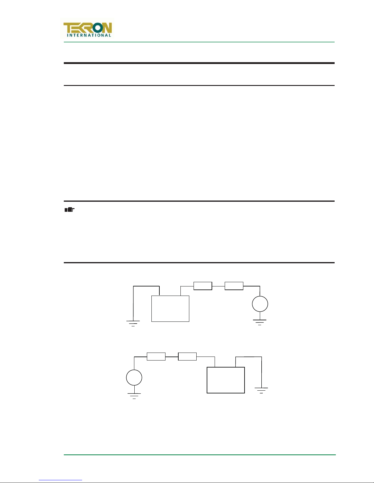
Figure 9 – High Voltage MOSFET output switch option: Suggested wiring arrangements
–
9thEdition: February 2007
7FACTORY HARDWARE OPTIONS
7.1 TCG 01 High Voltage Output Option
TCG 01 may be ordered with either or both of the P2 and P3 outputs configured with a
high voltage FET switching transistor instead of the standard 5V logic output. When so
fitted, each output can switch an external load of up to 300VA, with a maximum “on”
current rating of 1A, and a maximum rated Voltage of 300V DC.
External wiring should be arranged so that the external high voltage supply line (up to
300V DC max) is connected, via a fuse, to the load. The return connection from the load
is then wired to one terminal of the P
output is then wired to complete the circuit back to the other side of the power supply.
Do not connect the high voltage supply to P2 or P3 unless the high voltage option is
fitted – check the label on the base of the TCG 01 unit.
output, and the other terminal of the P
IMPORTANT! It is the user’s responsibility to provide adequate protection in the
form of an external fuse to protect the external power supply, the TCG 01
output switch and the load. Note: At all times, the polarity of the P2 (P3)
connections should be such that conventional current flow is into the “+”
terminal and out of the “0” terminal – i.e. “+” is at higher positive potential than
“0”.
Positive earth system
P2
+
TCG 01 with
HV MOSFET
Negative earth system
+
300Vdc max
0
300Vdc max
+ P2
TCG 01 with
HV MOSFET
0
–
Output isolation (from chassis and other I/O) is still maintained when the HV option is
fitted. This simplifies the external load/supply arrangements, particularly when operating
with positive-earth systems – as in many utility facilities.
Page 15 of 49
Page 22

7.2 Power Supply Options
Figure 10 – The Multi-port Hub option adds seven additional I/O to TCG 01
www.tekroninternational.com
DC Input Range AC Input Range
Low (L) 12 –36Vdc, 16-24Vac
Medium (M) 20-72Vdc 24-48Vac
High (H) 90-300Vdc 80-120Vac
This table shows the three different
power supply configurations that
maybeorderedwithTCG01.
7.3 Lightning Protection Option
A lightning Protection kit may be fitted into the antenna lead-in cable. The kit contains a
protection device, two coaxial cable connectors, a connector crimp tool, and mounting
hardware. Refer to Appendix B on page 28 for specifications and installation information.
7.4 Multi-port Hub Option
F
The Multi-port Hub option consists of seven additional BNC I/O ports in a unit that
matches and is mounted along-side TCG 01 in a 19" rack mount. TCG 01 with multi-port
option ships with both TCG01 and Multi-port Hub units pre-installed in the rack-mount.
7.4.1 I/O Specification
Designator Function Description
P9, P10 Inputs 1 & 2
TTL 600ohm input
impedance.
P11 Programmable output:
TTL 5V 75mA sink & source
P12-P15 Four outputs, each
independently switchable
between the modulated or
un-modulated form of
IRIG-B.
Share the same logical input channels as the
TCG-01 P6 inputs, but are indepen-dently
isolated.
Outputs the same logical signal as the TCG01’s P4-pin1 output, and is isolated.
Un-modulated: TTL 5V 25mA sink & source,
sharing a common ground between other
outputs switched to un-modulated.
Modulated:
isolated.
8Vp-p, 100ohm, transformer-
Page 16 of 49
Page 23

TCG 01 User Manual
F1
9thEdition: February 2007
8TCG01CONFIGURATION SOFTWARE
8.1 Introduction
A proprietary software configuration program ships with all
TCG 01 units. It provides the user access to all of TCG 01’s
programmable system operating parameters as well as the
programmable output options. If preferred, parameter setup can be carried out ex factory to customer specification.
In addition to the descriptions below, the various
configurable parameters are also described within the
program’s on-line help. Clicking on the “?” iconinthetop
RH corner of the window brings up the help cursor. Moving
the help-cursor over an option and clicking activates on-line help for that parameter.
Pressing F
while over a parameter also activates online-help.
The configuration tool requires a Windows PC (95, 98, 2000, ME, XP, NT all supported)
with a spare 9-pin serial port. The serial port of the TCG 01 must be connected to this PC
with either a straight through DB9-DB9 plug, or for DTE TCG 01’s a crossover cable. The
correct cable for this is supplied with TCG 01.
The configuration tool may be run without a clock attached; in this case it may view or
alter a pre-saved configuration file.
When first loaded the configuration tool will bring up a small status window, and scan
through available serial ports, to find a powered up TCG 01. If a TCG 01 is discovered a
snapshot of the current clock settings will be shown in the “Clock Setup” and “Output
Config” tabs, and a live time preview will be shown.
Once connected, the “GPS Setup” will also begin to show the status of the GPS including
any satellites that are being tracked. The “Refresh Data” button is used to re-attempt
connection to TCG-01 and will read in the current TCG-01’s settings. The “Write” button
is used to save and apply the changes to TCG 01.
What follows is a description of some of the TCG 01’s configurable parameters. Due to
continuous product improvement, these specifications are subject to change without
notice. On Clocks less than D8 firmware, some of these features will be unavailable.
Page 17 of 49
Page 24

www.tekroninternational.com
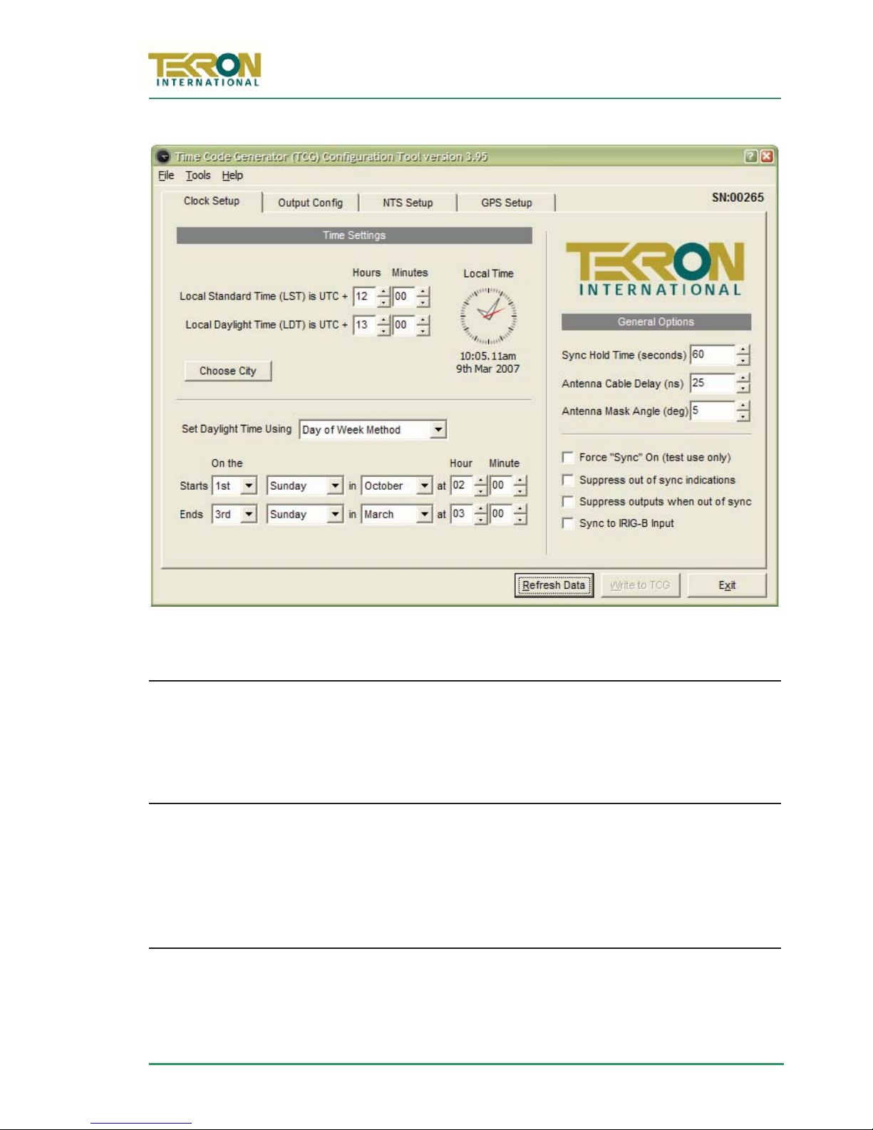
8.2 Local Time Settings
8.2.1 Local Standard Time and Local Daylight Time offsets
The time offsets define the number of hours (and, in rare cases, minutes) that the local
time differs from UTC time. A positive offset means that the local time is
automatic Daylight Saving Time operation is not required, both of the offsets should be
set to the same value
8.2.2 Local Time
When a TCG 01 is connected, this clock-face will be active, and is a preview of the
current time according to the current daylight savings and local time rules shown in the
configuration tool.
8.2.3 Choose City
The “Choose City” button provides a convenient way of automatically filling in time
offset and daylight savings parameters simply by selecting a geographical location.
. For UTC operation, both values should be set to zero.
aheadofUTC. If
8.2.4 Set Daylight Time Using
This allows configuration of TCG 01's Automatic Daylight savings changes based either
on a fixed date, or a fixed rule for calculating a date that will be different depending on
what year it is. Use the “Choose City” button to access a list of presets.
8.3 General Options
8.3.1 Sync Hold Time
The “Sync Hold” parameter is used to control the period after loss of satellite sync that
will be tolerated before TCG 01 will show loss of sync, and release the “sync” relay,
Correct installation will make the loss of sync event rare, although in areas with poor GPS
coverage there will be occasions where tracking is momentarily lost.
The accuracy of all outputs when there is a complete satellite “blackout” is maintained to
within a few micro-seconds over short periods (a few minutes), and to within 200us for
up to 40 minutes. A single satellite signal sufficiently recovers accuracy to within 1us.
In typical SCADA operations, time syncing to within 0.5ms is considered
adequate. Setting Sync Hold to the maximum (2550 seconds) will prevent “loss
of sync” alarms in the event that satellites are temporarily obstructed.
Page 18 of 49
Page 25
TCG 01 User Manual
Figure 11 – “Clock Setup” Page
TEST-ONLY MODE SHOULD NEVER
BE USED DURING NORMAL OPERATION
9thEdition: February 2007
F
8.3.2 Antenna Cable Delay Compensation
All antenna systems introduce signal delay (depending on the cable length). To optimise
the precision of the output signals enter the appropriate value in this field (20ns per
metre of antenna cable). E.g. For a 30 metre antenna cable, enter “120”
8.3.3 Mask Angle
This is the elevation above the horizon below which satellites will not be used in time
and position calculations. A good starting value is 5 degrees, and this may need to be
increased in areas with land based obstacles to prevent time quality loss due to
multipathing effects. Increasing this value will reduce the number of satellites in view.
8.3.4 Test Mode
Test Mode forces TCG 01 to report at all times that it is in sync to satellites, even if this is
not true (e.g. there is no antenna attached). In this mode the sync relay will be on at all
times, and the TCG 01 display will flash a warning. T
Page 19 of 49
Page 26

www.tekroninternational.com
Figure 12 – Multiple Time Code Generators, with one GPS Antenna
independently
p
8.3.5 Suppress Out of Sync Indications
This makes TCG 01 operate as if it is in sync at all times, even if there is no antenna
attached. The sync relay operation is unaffected by this option and will still indicate the
true sync state of TCG 01.
8.3.6 Suppress Outputs When Out of Sync
This option suppresses the TCG 01’s output signals on P2, P3, P4, P5 and the Time Server
when the clock goes out of sync. The sync relay operation is unaffected by this option
and will still indicate the true sync state of TCG 01.
8.3.7 Sync to IRIG-B Input
Checking this option, forces TCG-01 to get its synchronisation from an external IRIG-B
signal fed into the first input on the input plug P6 (terminals [+1, C]), overriding any
information from the GPS antenna. This feature allows multiple time code generators
from a single antenna. The slave TCG-01 receives synchronisation from a master TCG 01
that is producing IRIG-B, and will use the local time settings that are programmed into
the master TCG-01.
PS Antenna
TTL level IRIG-B with
IEEE extensions
nt
(P2 or P3)
Master
F
lave 1
ut [+1, C] P6 input [+1, C]
P6 in
lave 2
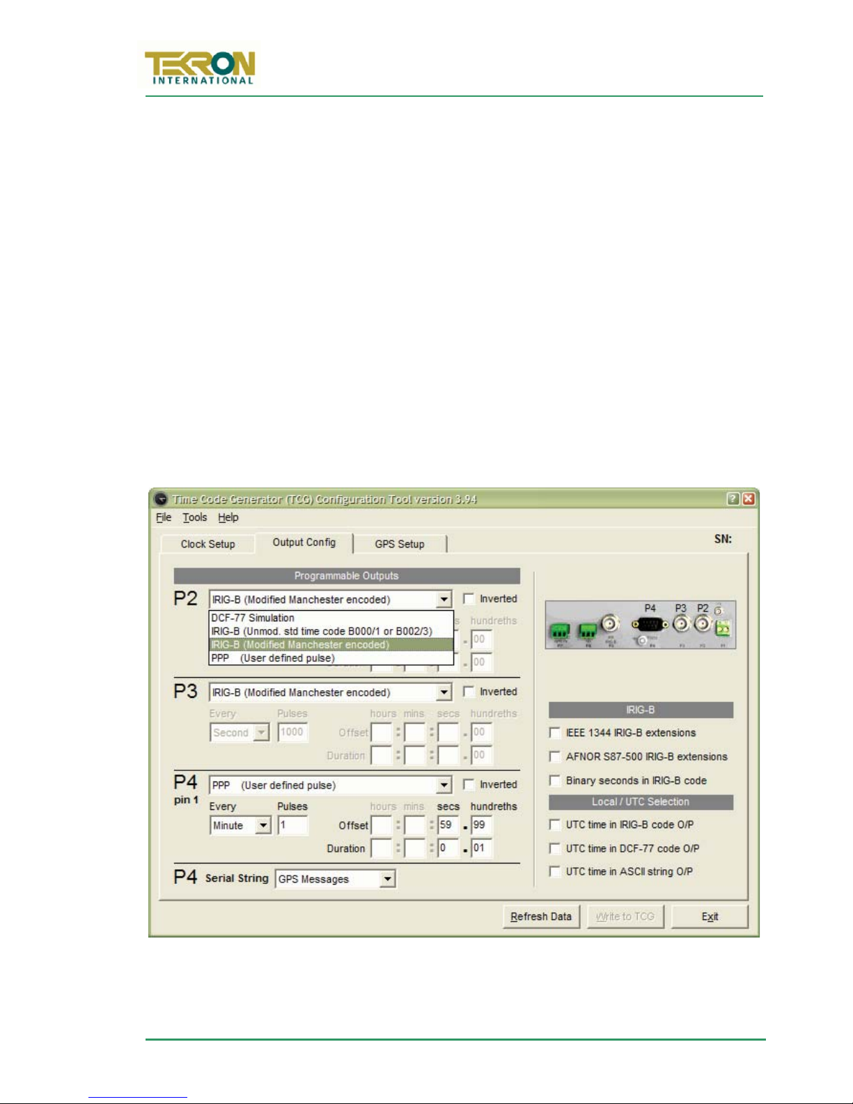
8.4 Programmable Outputs
8.4.1 P2 / P3 / P4-pin 1
Each of the three outputs (PP2,PP3and PP4-pin 1) can be programmed to give one of four
different output waveforms. Selection between the four options is done via a drop-down
menu. The options available i
for each output are:
Page 20 of 49
Page 27
TCG 01 User Manual
Figure 13 – “Output Config” Page
9thEdition: February 2007
1. DCF-77 output pulse simulation
2. IRIG-B NRZI (B000/B001 or B002/B003)
3. IRIG-B Modified Manchester Encoded (B220/B223 or B221/B222)
4. User Defined Pulse Sequence (separate definition stored for each output)
In the case of the User-Defined Pulse option being selected for any outputs, further
parameters are entered to define the pulse sequence. The parameters are as follows:-
A drop-down menu allows the user to choose to have pulses output “Every” “second”,
“minute”, “hour”, or “day”.
The “Pulses” field defines the number of pulses that will be produced in the selected
time interval. Selection is constrained to even divisors of the time interval.
The “Offset” data entry boxes specify how much time elapses into the defined time
interval before pulsing starts. Data validation rules ensure that only sensible entries can
be made.
The “Duration” data entry boxes specify the length of individual pulses.
F
Page 21 of 49
Page 28

www.tekroninternational.com
Figure 13 shows the settings for a user-defined pulse on the P4-pin1 output. The
values shown will result in a single pulse per minute. The pulse will begin 59.99
seconds after the start of the minute, and will last for 1/100thof a second (10ms).
These settings of the pulse output on P4-pin1 are normally used in conjunction
with the “NTGS ASCII” String on P4 to give an “NTGS synchronisation protocol”
8.4.2 P4 Serial String
The serial port output P4 operates at the fixed data rate of 9600bd with no flow control
and 8-bit, no parity format unless otherwise specified. The standard TCG 01 outputs are
broadcast messages sent at regular intervals. The broadcast repetition rates, timings, and
message content are all described in the Serial Output Strings Appendix on page 42.
Descriptions of each string are also built into the configuration tool; select the output
string from the drop-down list in the configuration tool, and press F1.
8.5 IRIG-B Options
8.5.1 Binary Seconds in IRIG-B
The “Binary Seconds” field is an option specified by IRIG standard 200-98. If this option
is checked, all of the outputs programmed for IRIG-B code – including the amplitudemodulated output - will include the “Binary Seconds of Day” data.
8.5.2 IRIG-B Extensions
IRIG Standard 200-98 specifies a 27-bit control field in the IRIG-B time codes, but does
not define the content. If either of the following options are checked,
- including the fixed AM output (P5) - will include the extension data in the control field.
IEEE1344 Extensions (US origin)
IEEE1344 defines fields for: Year, Impending leap second info, Local time offset info,
impending daylight savings change, time-quality.
AFNOR NF S87-500 Extensions (European Origin)
AFNOR S87-500 defines fields for: Day of year, day of week, year, month, day of month.
all
IRIG-B outputs
8.6 Local/UTC Selection
8.6.1 UTC Time in DCF-77, IRIG-B, ASCII String O/P
When checked, UTC time will be output in this time code. Otherwise Local time using
TCG 01's current Local Standard Time and Daylight Savings Time settings will be output.
Page 22 of 49
Page 29
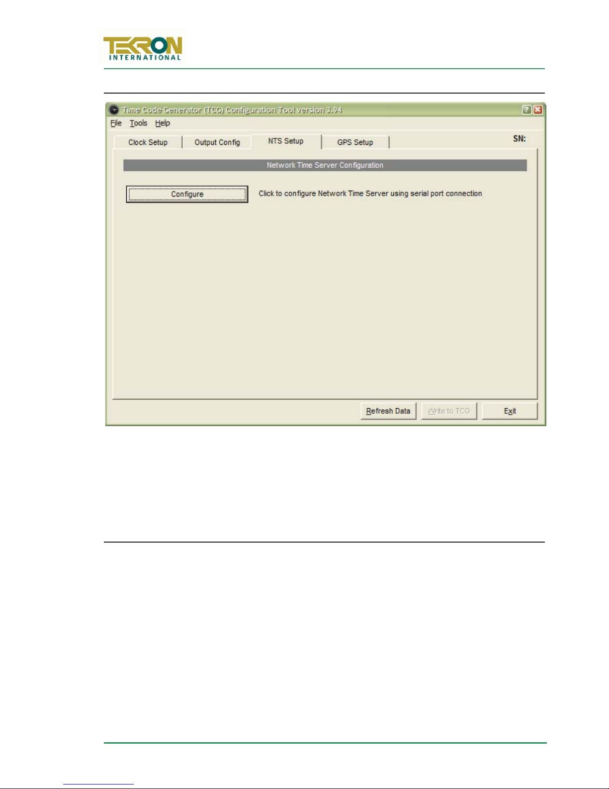
8.7 Network Time Server Configuration
Figure 14 – “NTS Setup" Page
TCG 01 User Manual
9thEdition: February 2007
F
The NTS Set-Up Page is displayed if a TCG 01 unit has a network time server. Click
“Configure” to bring up a terminal and configure the time server. |Appendix D (page 36)
describes the available options and the time server configuration process.
8.8 Visible Satellites
Visible satellites are shown on a polar-display. The rings mark the 'elevation' and the
sectors mark 'azimuth'. The centre of the display represents directly overhead and the
elevation is 90° at this point. The edge of the display, elevation = 0°, represents the
horizon. The 'azimuth' is a compass direction where 0° represents true north, 90° is east
and 180° is south. Satellites being used are marked by a coloured cross on the display,
and a blue bar on the Satellite Signal Strength Indicator, otherwise it is gray on both.
Right clicking over the Visible Satellites area, brings up a menu where satellite trails
(green lines), and a minimum elevation plot (the blue lines) can be turned on. Over time
this minimum elevation plot will show the viewable horizon. An example of a minimum
elevation plot is shown in Figure 15, which is from Wellington, New Zealand. This
example shows there is poor satellite coverage in southern latitudes.
Page 23 of 49
Page 30

www.tekroninternational.com
Figure 15 – GPS Setup Page, showing trails and minimum elevations turned on
F
To ensure reliable performance, when operating TCG 01 in extreme southern (or
northern) latitudes, ensure the antenna is positioned with a clear view of the
northern (or southern) sky
8.8.1 Setting Position and Time
Time and position may be pre-set using the set time and set location buttons only if TCG
01 has no satellite tracking history. To clear tracking history remove the antenna and
cycle power or use the “Reset GPS” button, although be prepared to wait! It may take
half an hour for the GPS, with a good antenna connected, to fully recover from a reset.
The ability to force any time and date into the instrument means that TCG 01 can be
used as a convenient signal source for testing the ability of externally attached
equipment to correctly process received time codes through unusual time transitions
such as the 28/29 Feb rollover during leap years, or daylight savings transitions.
Page 24 of 49
Page 31

TCG 01 User Manual
9thEdition: February 2007
Appendix A ANTENNA DETAILS
A.1 Antenna Cable Specification
The TCG 01 is supplied with 15, 30, or 60 metres of high performance RF cable factoryfitted with a TNC-type male connector at one end, and a SMA male connector at the
other. The TNC-type connector mates with the connector on the antenna and provides a
robust and weather-resistant connection. The smaller SMA connector mates with the
connector on the TCG 01 rear panel and is only fractionally larger in diameter than the
cable itself; this facilitates installation in conduit and through small apertures. The
supplied cable has the following characteristics:
Centre conductor: 1.42mm dia Solid bare copper
Dielectric: 3.81mm dia Low loss, closed polyethylene foam (Cellular PE)
Shield: 3.94mm diameter Aluminium Laminated Tape bonded to the
Dielectric, with a Tinned Copper Overbraid – 4.52mm diameter
Jacket: 6.10mm Black Polyethylene
Bending Radius: 40mm (maintaining less WKDQ impedance change at bend).
Weight: 0.051 kg/metre
Temperature Range: -40oCto +85oC
Impedance: 50
Velocity: 84%
Capacitance 79.4pf/metre
Centre
Resistance
Attenuation: 0.33dB per metre @ 1575.42MHz (L1)
Shielding: > 90dB
Phase Stability: +/- 10ppm/degree C
conductor
Shield: 2.8 per 1000 metre
10.5 per 1000 metreDC
Care should be taken during installation to ensure that the minimum bending radius
limit noted above is scrupulously maintained.
While the cable shielding is excellent, the c a ble should not be routed in close
proximity to power cables or other RF cables carrying transmitter signals – in
particular, parallel runs are to be avoided if possible. If such runs are absolutely
unavoidable, a minimum separation of 30cm may be used as a guideline.
The GPS receiver embedded in TCG 01 has excellent OOB rejection characteristics, as
does the antenna itself. However, sound engineering practice should not rely on these
factors alone to guarantee performance. Careful installation will enhance the long-term
reliability and on-going stability of the Time Code Generator.
Page 25 of 49
Page 32
www.tekroninternational.com
A.2 Antenna Specification
The TCG 01 unit’s standard shipping configuration includes an active GPS antenna
specifically designed for industrial/static timing environments, together with a pipemounting plinth.
Physical Specifications of NAIS Antenna
Diameter 90mmDimensions
Height 98mm tall (without connector or plinth)
Weight 200g
Color White
Electrical Specifications of NAIS Antenna
Polarisation Right hand circular polarisation
Bandwidth 1575.42MHz ± 1.023Mhz
Power Supply 5V dc ± 0.5V
Typical 20mACurrent
Drain Maximum 27mA
Typical 38dBiTotal Gain
At 90º
elevation
Attenuation 60dB at 1525MHz, 1625MHz (± 50MHz on centre frequency)
Output VWSR Typical 1.5
Output VWSR Maximum 2.5
Lightning Protection 80V for IEC100-4-5 standard
30dBi
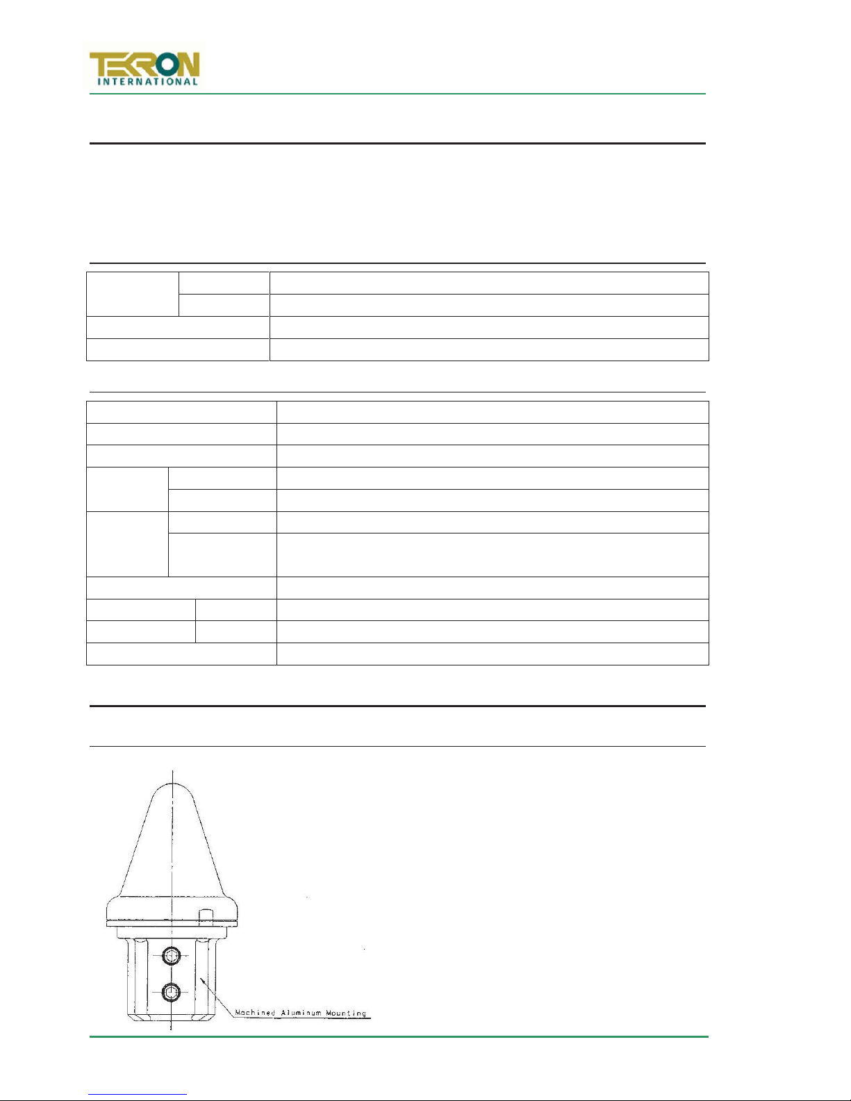
A.3 Antenna Assembly
NAIS Antenna Mounting
Page 26 of 49
The NAIS GPS antenna assembly for a 42mm
max outer diameter (1¼ inch/32mm inner
diameter) nominal galvanised pipe is shown
on the left.
The antenna mount is designed to fit over
the top of a user-supplied pipe like a
capping. The mount has an internal diameter
of 43mm, to fit a pipe with external diameter
of between 40 and 42mm (1¼ inch/32mm
nominal ID galvanised pipe). The top end of
the pipe should be cut flat, so that the rubber
Page 33

TCG 01 User Manual
9thEdition: February 2007
gasket inside the antenna mount sits flush against it, forming an effective weather seal.
The mount is fixed to the pipe with two stainless steel M8 hexagon- socket setscrews
(supplied).
The antenna cable is passed up through the pipe from the bottom end, and connects
directly to the connector on the base of the antenna. The metal base of the antenna is
fixed to the top flat surface of the mount by means of four captive screws in the mount.
The connector on Antennas shipped prior to July 2006 is an N type. The connector on
Antennas shipped after that date is a TNC type.
Suggested Assembly order
1. Select a suitable location where the antenna has a good view of the sky. Avoid close
proximity to antennas from other services where possible. The antenna has excellent
rejection characteristics to out-of-band signals, as does the TCG 01 GPS receiver, but
high-powered RF signals in close proximity to the antenna may swamp the very lowlevel signals from the GPS satellites.
2. Establish the mounting method for the pipe, such as strapping or bolting to a frame
on the edge of the building, or strapping to an air conditioning exhaust or similar.
Thebaseofthepipeneedstobeaccessibleforthecableentry,ifthisisnotpractical,
then a hole or slot can be made in the side of the pipe to allow the cable to enter
and be passed up to the top of the pipe.
3. Position the antenna cable inside the pipe, protruding from the top.
4. Screw the four stainless steel mounting screws in to the antenna mount, so that they
become captive, and then pass the mount over the top of the protruding cable, so
that the cable passes through the mount.
5. Connect the antenna to the cable, ensuring the N-connector is not cross-threaded,
and tighten the connector. Do not over-tighten! – firm hand tightening is sufficient!
The N-connector forms the inner weather seal for the electrical connection.
6. Position the antenna (connected to the cable) to the top of the mount, aligning the
mounting holes in the base so that the four captive screws in the mount line up.
Secure the antenna firmly to the mount using the captive screws.
7. Place the antenna and mount assembly, complete with the cable attached, squarely
over the top of the mounting pipe, allowing excess cable to fall back through the
pipe. Secure the antenna mount with the two setscrews, ensuring that the antenna
assembly remains firmly pressed against the end of the pipe, thus providing the
exterior weather seal. Secure the now complete antenna assembly and pipe to the
previously prepared mounting structure.
Page 27 of 49
Page 34

www.tekroninternational.com
Appendix B LIGHTNING PROTECTION OPTION
B.1 General
The first line of protection against the effects of lightning-induced surge events involves
positioning the antenna in a “lightning-protected zone” as far as is possible. In practice,
this means ensuring that there is at least one other earth-bonded structure located in
the same rooftop area (e.g. another antenna, or a lightning rod) that reaches
significantly higher than the top of the GPS antenna. The GPS Antenna should then be
mounted so that it lies within a 45-degree angle from the top of the other earth-bonded
structure. The GPS antenna mount itself should also be securely bonded directly to the
building protection earth – and
not
However, this will
strike, or voltages induced in the antenna lead-in cable due to side flashes or induction.
All Tekron antenna installations should follow the guidelines above – regardless
of whether a separate lightning protection device is to be fitted to the antenna
lead-in cable.
provide immunity from damage caused by a direct lightening
not
connected via any of the other earthed structures.
In areas with a low incidence of electrical storms, careful attention to antenna
positioning and earth connections may be all the protection deemed necessary. The
antenna lightning protection kit LPK01 affords additional security through the use of an
impulse suppressor installed in the antenna lead-in coax cable. In the event of a
lightning-derived high voltage surge occurring on the coaxial cable, the impulse
suppressor activates, short-circuiting the cable directly to the protection ground.
While the LP kit provides a high degree of p rotection, there is no guarantee of
protection against all surge related events, including a direct lightning strike to
the antenna. Careful antenna positioning is strongly advised!
The performance of the antenna system under normal (non-surge) conditions is virtually
unaffected by the introduction of a correctly installed EMP Protector.
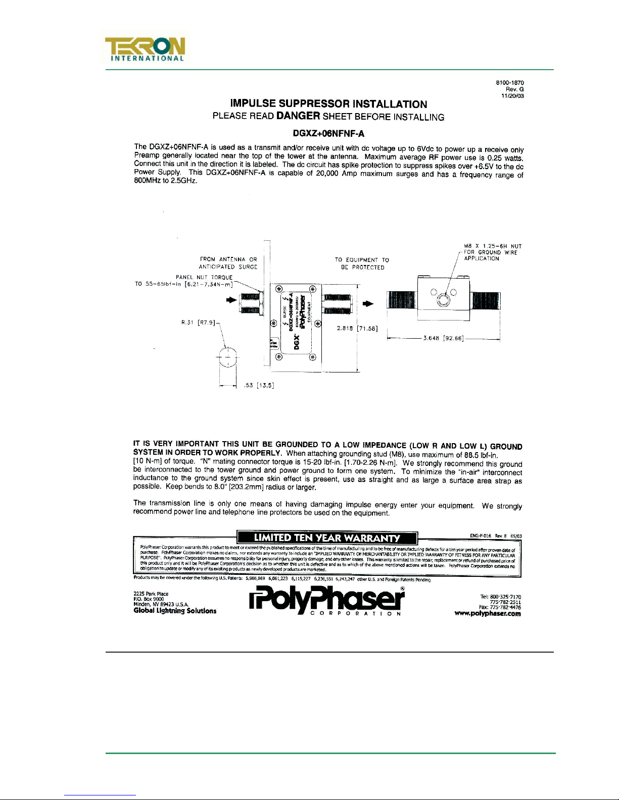
B.2 LPK01 Kit Contents
Quantity Description
1 Polyphasor DGXZ+06NFNF-A Impulse Suppressor
2 N-type Male Crimp Style Coaxial cable connector set to match antenna cable
1 Crimp Tool to match the above connectors (RG59)
1 Roll Self-amalgamating Insulation tape
Page 28 of 49
Page 35

TCG 01 User Manual
Please ensure that a
good electrical connection is made between the surge protector and the earthing
system.
essential
exactly
Use Option 2 measurements shown
9thEdition: February 2007
B.3 Installation
The impulse suppressor should be installed as per the instructions provided with the
impulse suppressor.
For the lightning protector to be effective, it must be firmly mounted to a conductive
metal surface that is itself bonded to the building protective earth. P
All earthing connections should be as short as possible, should have no sharp bends or
loops and should not be coiled to take up extra cable.
The preferred mounting position is on the inside of the building’s exterior wall, adjacent
to the antenna lead entry point.
The absolute minimum bend radius for the antenna cable supplied is 40mm, but
it is preferable to use a larger bending radius if possible. One way of achieving
this is by positioning the protector so that the incoming antenna lead comes
through the wall about 150mm away from the protector’s connector. This
provides some space to ease the incoming cable into a gentle arc back on to the
connector.
The antenna cable must be cleanly cut at the appropriate point and the resulting two
ends terminated with the N-type connectors provided. The connectors are then attached
to the protector assembly and tightened firmly by hand. Seal each of the connections by
stretch-wrapping them with the self-amalgamating tape supplied in the kit. The seal
provides protection against moisture ingress, and prevents the connections from
loosening over time.
Care must be taken to mount the N-type connectors to the coax cable correctly
according to Figure 16 (T00100B3300). As the GPS antenna operates at a frequency in
excess of 1.5GHz, it is
(U
included in the kit – use the 0.68” die for the centre pin and the 0.256” die for the
external hex housing.
that the cable be prepared
– all measurements in millimetres). A crimp tool is
as per the drawing
Page 29 of 49
Page 36

www.tekroninternational.com
Figure 16 – N-Type connector cable preparation and termination
F
Page 30 of 49
Page 37
TCG 01 User Manual
9thEdition: February 2007
B.4 Disclaimer
TEKRON INTERNATIONAL DISCLAIMS ANY LIABILITY OR RESPONSIBILITY FOR THE
RESULTS OF IMPROPER OR UNSAFE INSTALLATION PRACTICE INCLUDING, BUT NOT
LIMITED TO, ANY EXCESSIVE PERFORMANCE DEGRADATION OF THE ANTENNA SYSTEM
RESULTING FROM INCORRECT FIELD INSTALLATION OF COAXIAL CABLE CONNECTORS.
Page 31 of 49
Page 38

www.tekroninternational.com
Appendix C EVENT TIME-TAGGING OPTION
C.1 Introduction
General Description & Specification
TCG 01’s Event Time-Tagging Option provides for the time-stamping of rising edges
seen at either channel of P6. This is a TTL level input with an input burden of 7mA.
Event time is deemed to be the rising edge of a pulse. The minimum pulse duration is
1us, and the maximum rate of time tag recording is 100 tags per second (aggregated
over both inputs). In the event of pulses occurring simultaneously on both inputs, both
events are captured and recorded independently with the same time data.
Tag Data
Time Tags use UTC time, and each tag includes the year, day of year, hour, minute and
second, as well as fraction of second to a resolution and accuracy of 100ns. TCG 01
measures time internally in 40ns intervals, rounding to the nearest 100ns for time tag
storage purposes, thus allowing accuracy to equate to resolution. Each tag record
includes the input channel number, as well as the clock sync status as at the tag time.
Tag Storage
TCG 01 stores Time Tags in a data queue designed as a circular buffer. The maximum
number of time tags that may be stored is 512. If further events occur when the buffer is
full, TCG 01 sets an overflow status and continues storing tags, overwriting the oldest
data first.
Tag Retrieval
The user can retrieve time tags from the buffer using a request/response protocol
operating over TCG 01’s serial port interface. Tags are retrieved from the buffer - oldest
data first.
TCG 01 can be configured to broadcast either status or serial time strings over the serial
port. Most users of the time tag option will want to suppress all broadcast outputs to
are
simplify the task of time tag data collection. However, if output strings
then TCG 01 will still output time tag information when requested, timing the responses
to avoid interference with the other traffic on the port.
programmed,
Page 32 of 49
Page 39

TCG 01 User Manual
Ps command:
9thEdition: February 2007
C.2 TCG 01 Command / Response Message structure
Units equipped with the Time-Tagging (event recording) option provide four
command/response message pairs that specifically support Time Tag management and
retrieval.
All command and response messages used by TCG 01 have the same structure:-
Prefix: 2 bytes (ASCII “@” characters)
Type: 2 bytes (ASCII alphabetic characters - case matters!)
Data: n
Checksum: 1 byte, Binary XOR over all bytes in the “Type” and “Data” fields
Suffix: 2 bytes (ASCII <CR><LF>)
*
bytes (May be ASCII or binary data)
* The length of the “Data” field is determined by “Type”. Command
and Response commands, while sharing the same “Type” field, have
different data content and length.
C.3 TCG 01 Commands related to Event Time Tagging
These commands and their responses contain ASCII characters only. A tool such as telnet
provides a convenient way to explore the Time-Tagging command/retrieval functions
not
manually. Note that the TCG01 native serial protocol does
addressing. In a network-connected system, the address of the Serial to Ethernet
interface device can serve as the station address. Tekron International can supply such
devices if required.
P
Get Status
ThePscommandinvokesaPs response that contains the clock status – which includes
the number of tags currently in the time-tag event buffer.
Command (7 bytes [0-6]): Transmitted format: @@Ps#<CR><LF>
Response: (33 bytes [0-32]): Received format: @@Ps{26 data bytes}{cs}<CR><LF>
Byte # Description (Data bytes only, bytes 4-29 in received message)
4 Antenna feed fault –[A] only if antenna line is short or open circuit *
5 No GPS Solutions – [T] only if no satellites are available for time calculations *
6 S/N level low – [S] only if S/N level is abnormally low for more than an hour *
7 Oscillator Error High – [X] only if Oscillator Control value is extreme *
8 Oscillator DAC out of range – [H] or [L] only if Oscillator Control tending
towards extreme *
9 GPS Fail – [B] only if internal GPS receiver sub-system not operating properly *
10 Not implemented – ASCII [space] always
11 Tracking Satellites – [0-9] = # of satellites in time solution (see note 1 below)
include station
Page 33 of 49
Page 40

www.tekroninternational.com
mode=1:
mode=2:
mode=3:
Pc command:
12 Receiver Operating Mode – [0-5] see note 2 below
13 –
15
16 –
18
19 –
20
21 Oscillator Correction. Most significant 4 bits of 16-bit D/A converter used for
22 Oscillator Correction. More significant 6 bits of 16-bit D/A converter used for
23 Oscillator Correction. Least significant 6 bits of 16-bit D/A converter used for
23 Frequency Error. Local Oscillator frequency offset as compared with GPS
Time Tag Queue Indicator – [000-512, 999] # of tags in queue (999=overflow)
Outage Indicator – [000-999] Hours since receiver was last locked to GPS
signals. Becomes non-zero one hour after loss of lock. Resets to zero when
lock is re-acquired
Outage Indicator – [00-59] Minutes since receiver was last locked to GPS
signals. Becomes non-zero one minute after loss of lock. Resets to zero when
lock is re-acquired.
oscillator control. Range is ASCII [@] to [O] (hex 40 to hex 4F)
oscillator control. Range is ASCII [@] to [del] (hex 40 to hex 7F)
oscillator control. Range is ASCII [@] to [del] (hex 40 to hex 7F)
received signal. In ASCII, ±00000-99999 referenced to 1E-12
Notes concerning the Ps command:
* An ASCII [space] is transmitted if there is no alarm condition present
1. TCG 01 can track up to 12 satellites simultaneously. The message limitation of
9 is to retain compatibility with older equipment using this message format.
2. m
The Pc command invokes a Pc response that returns the number of time-tags that were
in TCG 01’s event buffer when the Pc command was received. The event buffer is then
cleared.
Command (7 bytes [0-6]): Transmitted format: @@Pc3<CR><LF>
Response (10 bytes[0-9]): Received format: @@Pc{3databytes}{cs}<CR><LF>
Byte # Description (Data bytes only, bytes 4-6 in received message)
4 – 6 ASCII [000-512, 999] Number of time-tag entries in TCG 01 queue before reset.
satellite search, 2D/3D fix,
GPS Automatic site survey,
GPS position hold (most accurate time)
Clear Time-Tag Buffer
Page 34 of 49
Page 41

TCG 01 User Manual
Pt command:
Pr command:
9thEdition: February 2007
P
Get next Time-Tag
The Pt command invokes a Pt response that contains a single time-tag record – the
oldest one in the data queue. Successive “Pt” commands will result in successive time tag
data being retrieved. If the queue is empty, the Pt response is a null time tag. (ASCII [0]
characters in all fields except delimiters).
Command (7 bytes [0-6]): Transmitted format: @@Pt$<CR><LF>
Response (33 bytes [0-32]): Received format: @@Pt{26 data bytes}{cs}<CR><LF>
Byte # Description (Data bytes only, bytes 4-29 in received message)
4 Day of Year in ASCII, 001 to 366
7 Delimiter, ASCII [:] (hex 3A)
8 – 9 Hour of Day in ASCII, 00-23
10 Delimiter, ASCII [:] (hex 3A)
11 –12 Minute of Hour in ASCII, 00-59
13 Delimiter, ASCII [:] (hex 3A)
14 – 15 Second of Minute in ASCII, 00-60
16 Delimiter, ASCII [.] (hex 2E)
17 – 23 Fraction of Second in ASCII (100’s of nanoseconds), 0000000-9999999
24 Quality Indicator. Codes are:
ASCII [space] (hex 20) if receiver locked, sub-100nS Output accuracy
ASCII [?] (hex 3F) if receiver unlocked for more than 1 minute
ASCII [*] (hex 2A) if receiver in alarm mode – antenna fail
25– 27 Outage Indicator – [000-999] Hours since receiver was last locked to GPS
signals. Becomes non -zero one hour after loss of lock. Resets to zero when
lock is re-acquired.
28 Delimiter, ASCII [#] (hex 23)
29 Number of Time-Tag Channel in ASCII, 1-2
Repeat last Tag Sent
The Pr command invokes a Pr response that contains a single time-tag record – the
same data that was sent in response to the last Pt command.
Command (7 bytes [0-6]): Transmitted format: @@Pr”<CR><LF>
Response (33 bytes [0-32]): Received format: @@Pr{26 data bytes}{cs}<CR><LF>
Data format is identical to Pt data format above
Page 35 of 49
Page 42

www.tekroninternational.com
Appendix D NETWORK TIME SERVER OPTION
D.1 Configuration Requirements
Configuration of the NTS involves setting the unit’s TCP/IP networking parameters (IP
Address, Net-Mask and Gateway IP Address settings), the number of tracked satellites
required to initiate the Server function, and optionally, the IP addressing data needed
for SNMP status reporting. Although not strictly necessary, it is usual to assign a fixed IP
address to the NTS module, even in network environments operating with a DHCP
Server. This allows NTP client software on all work-stations to be permanently
programmed to poll to the fixed address of the NTP Server.
It is beyond the scope of this document to discuss TCP/IP addressing concepts in
detail. The configuration instructions below assume some familiarity with the
TCP/IP networking environment and Network Operating System utilities such as
“Ping”, “Telnet” and “Arp”.
The following TCP/IP information is required to configure the NTS properly:
(a) The fixed local network address (IP address) to be assigned to the NTS.
(b) The number of bits in the netmask that the local network assigns to hosts. The
default setting of “0” results in automatic allocation.
(c) The IP address of the gateway router (only necessary if the NTS is required to
service clients on multiple sub-nets). The default is all null – no subnets.
(d) The IP address(es) to which SNMP status information should be sent (should be
set to null if no SNMP status reporting is required – the default setting.)
(e) The name of the SNMP community to which the NTS is to belong (should be set
to null if no SNMP status reporting is required – the default setting.)
D.2 Methods for Accessing Set-Up Mode
There are two ways to access the timeserver’s configurable options:
Access Using Configuration Software:
Connect the TCG 01 to a Windows PC using a serial cable and, using the configuration
tool, select the “Configure NTS” button in the “NTS Setup” tab of the configuration
program. This method has the advantage of being always available. There is no need to
know the network address of the unit, and there is no password protection using this
configuration method.
Page 36 of 49
Page 43

TCG 01 User Manual
H
9thEdition: February 2007
Login using a “Telnet” connection
This method has the advantage of not requiring the operator to be present at the
installed location. However the existing IP address of the NTS must be known before a
Telnet connection can be made. Both methods access the same options and menus. A
complete description of the NTS “Set-Up Mode” configuration menus and options starts
on p36.
D.3 Using Telnet to access Set-Up Mode
Provided that the NTS IP address is already configured and known, then the time server
can be configured using a Telnet Session to port 9999 on the known NTS IP address.
not
If the NTS IP address is
network access can be gained. A temporary IP address can be assigned in one of two
ways:
configured, an address must be temporarily assigned before
Assigning an IP address using DHCP addressing:
Networks that include a DHCP server offer automatic address allocation via DDynamic
ost CConfiguration PProtocol. (DHCP). The time server will automatically operate within a
DHCP environment to fetch a dynamic address if it does not already have a fixed
address configured. Each time server has a unique system name that will show up on the
DHCP Server’s active lease list within a few seconds of the DHCP Server granting an
address to the NTS. Examination of the list will reveal the allocated address. The naming
convention used by the time server is a “C” followed by the last six characters of the time
server’s permanent MAC address. For example: If the TCG 01 unit has a MAC Address of
00-20-4A-72-08-B7, then the DHCP name of the NTS is: C7208B7.
Each TCG 01 equipped with a time server has a label on its base that shows the
permanent MAC address of the unit.
Assigning an IP address using ARP addressing:
The ARP method is available under UNIX and Windows and can be used in systems
where no DHCP server is present. The TCG 01 NTS will set its address from the first
directed TCP/IP packet it receives.
On a Unix host, create an entry in the host’s ARP table using the intended IP address and
the hardware MAC address of the NTS (found on the label on the base of TCG 01). The
UNIX command (for example addresses IP: 192.168.1.56 and MAC: 00-20-4A-72-08-B7)
is:
arp –s 192.168.1.56 00:20:4A:72:08:B7
Page 37 of 49
Page 44

www.tekroninternational.com
ARP –A
Figure 17 – NTS Set up mode, Main Menu
In order for the ARP command to work correctly in Windows, the ARP table on the PC
must have at least one IP address defined other than its own. If the command A
typed from the DOS prompt results in only the local IP address being shown, then “ping”
any other known IP address on the network to establish a non-local entry. Once another
entry is established, use the same command as above to ARP an IP address to the NTS.
Next, open a Telnet connection to port 1 using the command:
telnet 192.168.1.56 1
This Telnet connection will quickly fail (3 seconds) but the NTS will change its IP address
to the one specified. Finally, open a new Telnet connection to port 9999 using the
command:
telnet 192.168.1.56 9999
The IP address set above will revert to the default null address if the NTS is
powered down or reset unless the full Set-Up procedure is completed and all of
the changes stored permanently using option 9 on the Set-Up menu.
D.4 NTS Set-Up Mode Menu
The NTS Set-Up mode menu displays the configuration of the time server, followed by a
menu. The menu display is similar for both configuration tool and network access.
Hardware: E thernet Autodetect
IP addr – 0.0.0.0/DHCP/BOOTP/AutoIP, no gateway set
DHCP device name : not set
******* Tekron NTS parameters *******
SNTP Ref.Id entifier : “GPS” Encryption is disabled
Visible Satellites : 1
******* Tekron NTS parameters *******
Community Name : public
Enter 1. Trap destination IP Address : --- not set --Enter 2. Trap destination IP Address : --- not set --Enter 3. Trap destination IP Address : --- not set --Enter 4. Trap destination IP Address : --- not set --Enter 5. Trap destination IP Address : --- not set --Syslog IP addr : --- not set --- --- not set --Syslog facility code: 0
Change Setup :
0 Basic parameters
1 NTS configuration
7 Factory defaults
8 Exit without save
9 Save and exit
Your choice ?
Page 38 of 49
Page 45

TCG 01 User Manual
Broadcast Mode
Encryption
No. of Satellites
Range 0-8.
9thEdition: February 2007
0 - Basic Parameters
This menu option allows permanent values to be assigned to the basic address
parameters of the NTS module. As a minimum, the primary IP Address should be set. The
other parameters that can be specified under this menu are:
x Gateway IP Address
x Number of bits in netmask
If the primary IP address is not changed from the default null value, then this menu will
also included an option for setting the DHCP name. When operating with a DHCPassigned address, the Tekron NTS has a permanently assigned DHCP name of Cxxxxxx
where xxxxxx is the last 6 digits of the MAC address of the unit (shown on the label on
not
base of the TCG 01 unit). Despite appearances, the DHCP name is
this menu option.
1 - NTS configuration
Selecting this option brings up prompts to set up the parameters required to operate
the NTS function. For most applications, the default settings will be appropriate. The
parameters that can be set are as follows:-
changeable under
B
Defaults to “N”. If “Y” is selected, the unit prompts for a poll interval. The unit will then
broadcast time packets at the interval specified. Note that, while in broadcast mode, the
unit will still respond to NTP/SNTP client requests in the usual manner. In most
applications, Broadcast Mode is not used, so the default is the appropriate setting.
Defaults to “N”. Most users will not use encryption. The TCG 01 NTS option supports fully
encrypted requests from up to 6 clients simultaneously. If the answer “Y” is selected
here, the unit then prompts for six encryption MAC strings. A good rule is – if you do
not already know what MAC data to use – don’t attempt to use encryption at all, and
leave the option at “N”.
Defaults to ““1”.R
If there are not this many GPS satellites being tracked for
time, a SNMP message “low satellites” is generated. As TCG 01’s true clock accuracy
when tracking just a single satellite is at least two orders of magnitude better than what
can be practically handled on the network, the default value of “1 ” is sufficient for
detection of this condition.
Page 39 of 49
Page 46

www.tekroninternational.com
Community
SNMP Trap IP Address
Syslog IP Addr
Syslog facility code
9 Exit
and Save.
2 - SNMP configuration
The Tekron NTP server provides status monitoring to Network Management systems
through the use of SNMP trap messages. The parameters that can be set are as follows:-
C
The default value is “public”. This may be changed to suit the specific SNMP architecture
on the network if required. If SNMP is not implemented for other purposes on the
network, then the “public” setting allows the use of a simple SNMP trap display utility
running on a remote monitoring PC to display the status messages sent from the NTS.
This parameter allows for up to five destination IP addresses to be entered. Machines on
any or all of these IP addresses can then receive the status messages from the NTS unit.
Even if there is no formal SNMP system running on the network, the messages can be
received and displayed on the destination machines running “Windows NT” or higher
using the freeware utility “SNMPTRAP.EXE” which is on the CD supplied with the kit.
One or two IP addresses may be entered to define destination machines running system
logs. These parameters are really only useful in networks running full SNMP network
management systems. Similarly, the following S
useful on full SNMP network systems.
Once configuration is complete, the set-up session may be terminated via option 9
“HyperTerm” response on the PC may well go “strange” as soon as the NTS resets. This
simply indicates that TCG 01 has reverted to normal operation on the serial port,
transmitting whatever output options are programmed via the TCG 01 configuration
program.)
The NTS will then reset and begin normal operation. (Note that the
parameter is only
D.5 Time Server Operation
The time-server’s operation is completely automatic once it is correctly configured for
the network. Time-server configuration info is retained indefinitely when the unit is not
powered (like all other TCG 01 configuration data). The time-server responds to time
requests from multiple clients using either SNTP or NTP protocol. If the option is
selected, the server will also broadcast time messages on a regular basis. The most
common protocol in use is SNTP. A sample SNTP client (freeware) for use on Windowsbased PC’s (prior to Windows XP) is included with each TCG 01 equipped with the NTS
option. Windows XP contains an NTP client as part of the operating system.
Page 40 of 49
Page 47

TCG 01 User Manual
Figure 18 – Time server port on TCG-01 showing lck, lnk, err, and sec indicators
9thEdition: February 2007
Correct operation of the Network Time Server can be verified by installing an SNTP
client on any Windows-based PC attached to the network. A very simple and effective
client, “Dimension 4” is included with the TCG 01 package (3 licenses are provided.
Additional licenses may be purchased from Thinking Man Software: www.thinkman.com
All that is required to use “Dimension 4” is, after the program is installed on the PC, add
the IP address of the TCG 01 NTS to the list of Time Servers, and select it. “Dimension 4”
will then use this address to fetch time information and sync the PC clock. “Dimension
4” installs complete with a list of internet time server addresses. To avoid any confusion,
it is suggested that the user remove all of these addresses, leaving only the local NTS
address.
)
F
The green lnk LED indicator on TCG 01 lights when a network cable (UTP drop lead) is
correctly connected between the TCG 01 RJ45 port and the local network hub/switch.
The other green LED, the lck indicator, lights up steadily when the NTS is correctly
synchronised with UTC time. Provided that TCG 01 is already synced to UTC time from
the GPS satellite constellation (Front Panel SYN led on), the lck indicator should stabilise
and remain on. If the lck indicator does
not
stabilise “on”, even though TCG 01 is in sync
with the GPS time, the most likely problem is that the NTS satellites parameter is set at
too high a value.
The two lower indicators err and sec should remain off during normal operation. These
indicators may flash for a few seconds immediately following power-on, but after the
unit has initialised and has a valid network address, they should go off and stay off. They
will flash continually when the NTS module is in set-up mode.
Page 41 of 49
Page 48

www.tekroninternational.com
Appendix E SERIAL OUTPUT STRINGS
E.1 NGTSTimeCodeO/PonP4
Timing Transmitted once per minute. Sent during the last second before the
minute rollover to which the data in the string refers
About Normally used in conjunction with 10mS pulse on P4 pin 1 that finishes
precisely on the minute. See the hint in Section 8.4.1.
Comms 9600bd, 8-bit ASCII, no parity
Definition TYYMMWhhmmx<CR><LF>
Placeholder Content
T"T"
YY Last two digits of the year: e.g. “12” = the year 2012
MM Month: “00” = January … “12” = December
W Day of week: “01”=Monday … “07”=Sunday
hh Two digit hour
mm Two digit minute
x Time mode: ”0” = Local time, “1” = UTC time
<CR> Carriage Return: HEX 0A
<LF> Line Feed: HEX 0D
Example Interpretation
T020422112340<CR><LF> Monday 22 April 2002 – 12:34 local time
E.2 IRIGJ-17TimeCodeO/PonP4
About This code is compatible with IRIG Standard 212-00
Timing Transmitted once every second. The leading edge of the “start” bit of the
first character <SOH> is exactly on the second that the message describes.
Comms 9600bd, 7-bit ASCII, odd parity
Definition <SOH>DDD:hh:mm:ss<CR><LF>
Placeholder Content
<SOH> HEX 01
DDD Day of year: range “001”—“365”
:HEX3A
hh hour: “00”—”23”
mm minute: “00”—“2
ss Seconds: “00”—“59”
<CR> HEX 0A
<LF> HEX 0D
Example Interpretation
<SOH>112:12:34:36<CR><LF> day 112, time 12:34:36
Page 42 of 49
Page 49

TCG 01 User Manual
9thEdition: February 2007
E.3 String-A Time Code O/P on P4
About This code is very similar in data content to the IRIG J-17 code, but adds a
two-character field containing the year, and uses 8-bit ASCII, no parity
data format
Timing Transmitted once every second. The leading edge of the “start” bit of the
first character <SOH> is exactly on the second that the message describes.
Comms 9600bd, 8-bit ASCII, no parity
Definition <SOH>DDD:hh:mm:ss:YY<CR><LF>
Placeholder Content
<SOH> HEX 01
DDD Day of year: range “001”—“365”
:HEX3A
hh hour: “00”—”23”
mm minute: “00”—“59”
ss seconds: “00”—“59”
YY year: “00”—“99” representing the last two digits of the year
<CR> HEX 0A
<LF> HEX 0D
Example Interpretation
<SOH>112:12:34:36<CR><LF> day 112, time 12:34:36
E.4 String-B Time Code O/P on P4
About This code substitutes a “Quality” indicator byte for the year field, but
otherwise is identical in form, function and timing to String-A.
Timing Transmitted once every second. The leading edge of the “start” bit of the
first character <SOH> is exactly on the second that the message describes.
Comms 9600bd, 8-bit ASCII, no parity
Definition <SOH>DDD:hh:mm:ss:Q<CR><LF>
Refer to String-A table (above) for the definitions of the common digits:
“Quality” Character (Q) Meaning
HEX ASCII
20 <Space> Clock in sync, timing accuracy is better than 60nS
2E . (full stop) Clock is accurate to 1uS
2A * Clock is accurate to 10uS
23 # Clock is accurate to 100uS
3F ? Clock accuracy may be worse than 100uS
Example Interpretation
<SOH>112:12:34:36?<CR><LF> day 112, time: 12:34:36, >100uS sync error
Page 43 of 49
Page 50

www.tekroninternational.com
E.5 String-C Time Code O/P on P4
About This code is effectively a combination of String-A and String B. It provides
both year information and a sync indicator field.
Timing Transmitted once every second. The leading edge of the “start” bit of the
first character, <CR>, is exactly on the second to which the message data
refers.
Comms 9600bd, 8-bit ASCII, no parity
Definition <CR><LF>QYYDDDhhmmss.000
Placeholder Content
<CR><LF> HEX 0A,0D
Q Quality indicator: “ “ = in-sync, “?” = out-of-sync
YY Year: “00”—“99” representing the last two digits of the year
DDD Day of year: range “001”—“365”
hh hour: “00”—”23”
mm minute: “00”—“59”
ss seconds: “00”—“59”
.000 ASCII “.000”
HEX 20 (ASCII “ “)
Example Interpretation
<CR><LF>? 02 112 12:34:36.000 day 112 of year (20)02,
time: 12:34:36, out-of-sync
N.B. in the above example the three trailing spaces as described in the definition are
invisible.
E.6 String-D Time Code O/P on P4
Tekron-D is IDENTICAL in content to String-B, but the second mark is at the leading
edge of the start-bit of the (<CR>).
Example Interpretation
<SOH>112:12:34:36?<CR><LF> day 112, time: 12:34:36, >100uS sync error
Page 44 of 49
Page 51

TCG 01 User Manual
9thEdition: February 2007
E.7 String-E Time Code O/P on P4
About This provides time, year information, and a sync indicator field.
Timing The string is transmitted once every second, with the leading
edge of the “start” bit of the <CR> exactly on the second.
Comms 9600bd, 8-bit ASCII, no parity
Definition <SOH>YYY:DDD:hh:mm:ssQ<CR><LF>
Placeholder Content
<SOH> HEX 01
YYY 3-digit year, e.g. “012” = 2012
:HEX3A
DDD Day of year: range “001”—“365”
hh hour: “00”—”23”
mm minute: “00”—“59”
ss seconds: “00”—“59”
Q Quality character, as defined in String-B (above)
Example Interpretation
<SOH>004:112:12:34:36?<CR><LF> (2)004, day 112, 12:34:36pm, >100us sync error
E.8 String-F Time Code O/P on P4
Timing The string is transmitted once every second, with the leading edge of the
“start” bit of the first carriage return (<CR>) exactly on the second.
Comms 9600bd, 8-bit ASCII, no parity
Definition <CR><LF>1100<CR><LF>44hhmmss<CR><LF>54ddd<CR><LF>
<CR><LF>45HHMMss<CR><LF>55DDD<CR><LF><BEL>
Placeholder Content
<CR><LF> HEX 0A, 0D
1100 ASCII “1100”
44 ASCII “44” (means local time follows)
54 ASCII “54” (means local day of year follows)
45 ASCII “45” (means UTC time follows)
55 ASCII “55” (means UTC day of year follows)
ddd Local day of year: “001”—“365”
hh Local hour of day: “00”—”23”
mm Local minute of day: “00”—“60”
ss seconds: “00”—“59”
DDD UTC Day of year: “001”—“365”
HH UTC hour: “00”—”23”
MM UTC minute: “00”—“59”
<BEL> HEX 07
Page 45 of 49
Page 52

www.tekroninternational.com
E.9 NMEA ZDA Time Code O/P on P4
About This string is compatible with and defined by the NMEA-0183 standard
Timing Transmission is once every second. The leading edge of the “start” bit of the
“$” is exactly on the second.
Comms 9600bd, 8-bit ASCII, no parity
Definition $GPZDA,hhmmss.00,DD,MM,YYYY,xx,yy*CC<CR><LF>
Placeholder Content
$GPZDA ASCII “$GPZDA”
, ASCII “,” (comma)
hh UTC hour of day: “00”—”23”
mm UTC minute of day: “00”—“60”
ss UTC Seconds: “00”—“59”
.00 ASCII ”.00”
DD UTC day of month: “01”—“31” depending on which month
MM UTC month: “01”—“12”, “01” = January
YYYY UTC year, 4 digit.
xx Local time zone offset from UTC in hours¹
yy Local time zone offset from UTC in minutes¹
* ASCII “*”
CC 2-digit hex representation of the result of XORing the 8
data bits of each character between, but not including the
"$" and "*". (00-FF)
<CR><LF> HEX 0A, 0D
Page 46 of 49
¹set to zero when UTC time in ASCII string is selected
Page 53

TCG 01 User Manual
9thEdition: February 2007
E.10 NMEARMC Time Code O/P on P4
About This string is compatible with and defined by the NMEA-0183 standard
Timing Transmission is once every second. The leading edge of the “start” bit of
the “$” is exactly on the second.
Comms 9600bd, 8-bit ASCII, no parity
Definition $GPRMC,hhmmss.00,a,tt,tt.tttt,n,ggg,gg.gggg,w,0.0,0.0,DDMMYY,0.0,E*CC
<CR><LF>
Placeholder Content
$GPZDA ASCII “$GPRMC”
, ASCII “,” (comma)
hhmmss UTC hour of day, minute of day, seconds
. ASCII “.” (full stop)
0 ASCII “0”
a Status: “A” = valid, “V” = invalid
tt,tt.tttt Latitude (degrees, minutes): “00,00.0000”—“89,59.9999”
N Latitude (north/south): “N” = north, “S” = south
ggg,gg,gggg Longitude (degrees, minutes): “000,00.0000”—
“359,59.9999”
W Longitude (east/west): “E” = east, “W” = west
DDMMYY UTC day of month, month, 2-digit year:
E* ASCII “E*”
CC 2-digit hex representation of the result of XORing the 8
data bits of each character between, but not including the
"$" and "*".
<CR><LF> HEX 0A, 0D
Page 47 of 49
Page 54

www.tekroninternational.com
A return material authorisation number issued by Tekron must accompany all return material.
WARRANTY STATEMENT
Tekron International Ltd (Tekron) warrants for a period of TWO years from the date of shipment
that each Product supplied shall be free of defects in material and workmanship. During this
period, if the customer experiences difficulty with a product and is unable to resolve the
problem by phone with Tekron Technical Support, a Return Material Authorisation (RMA) will be
issued. Following receipt of an RMA number, the customer is responsible for returning the
product to Tekron, freight prepaid. Tekron, upon verification of warranty will, at its option, repair
or replace the product in question and return it to the customer, freight prepaid. No services are
handled at the customer’s site under this warranty.
Tekron shall have no obligation to make repairs, or to cause replacement required through
normal wear and tear or necessitated in whole or in part by catastrophe, fault or negligence of
the user, improper or unauthorised use of the Product, or use of the Product in such a manner
for which it was not designed, or by causes external to the Product, such as, but not limited to,
power or failure of building services.
There are no understandings, agreements, representations or warranties, express or implied,
including warranties of merchantability or fitness for a particular purpose, other than those
specifically set out above or by any existing contract between the parties. Any such contract
states the entire obligation of Tekron. The contents of this document shall not become part of or
modify any prior or existing agreement, commitment or relationship.
The information, recommendation, description and safety notations in this or other documents
supplied by Tekron are based on general industry experience and judgement with respect to
such hardware and software. THIS INFORMATION SHOULD NOT BE CONSIDERED TO BE ALL
INCLUSIVE OR COVERING ALL CONTINGENCIES. NO OTHER WARRANTIES, EXPRESS OR IMPLIED,
INCLUDING WARRANTIES OF FITNESS FOR A PARTICULAR PURPOSE OR MERCHANTABILITY, OR
WARRANTIES ARISING FROM COURSE OF DEALING OR USAGE OF TRADE, ARE MADE
REGARDING THE INFORMATION, RECOMMENDATIONS, DESCRIPTIONS AND SAFETY
NOTATIONS CONTAINED HEREBYAND IN HARDWARE AND SOFTWARE SPECIFICATION
DOCUMENTATION, OR INSTRUCTIONS SUPPLIED BY Tekron. In no event will Tekron be
responsible to the user in contract, in tort (including negligence), strict liability or otherwise for
any special, indirect, incidental or consequential damage or loss of equipment, plant or power
system, cost of capital, loss of profits or revenues, cost of replacement power, additional
expenses in the use of existing software, hardware, equipment or facilities, or claims against the
user by its employees or customers resulting from the use of the information, recommendations,
descriptions and safety notations supplied by Tekron. Tekron liability is limited (at its election) to
(1) refund of buyer’s purchase price for such affected products (without interest); (2) repair of
such products, or (3) replacement of such products, provided however, that the buyer follows
the procedures set forth herein.
Warranty claims must be received by Tekron within the applicable warranty period. A replaced
product, or part thereof, shall become the property of Tekron and shall be returned to Tekron at
the Purchaser’s expense.
A
Page 48 of 49
Page 55

TCG 01 User Manual
9thEdition: February 2007
NOTES
The information in this manual may change without notice. The manufacturer assumes
no responsibility for any errors that may appear in this manual.
Ethernet is a trademark of XEROX Corporation. UNIX is a registered trademark of The
Open Group. Windows 95, Windows 98, Windows 2000, Windows NT and Hyperterm are
trademarks of Microsoft Corp. WinOncore12 and Oncore are trademarks of Motorola
Inc.
Copyright ©2003 Tekron International Ltd. All rights reserved. No part of the contents of
this document may be transmitted or reproduced in any form or by any means without
the written permission of Tekron International Ltd. Published in New Zealand.
WARNING
This product has been designed to comply with the limits for a Class A digital device
pursuant to Part 15 of FCC rules. These limits are designed to provide reasonable
protection against such interference when operating in a commercial environment.
Page 49 of 49
 Loading...