

Page 1
TR-824
SATA Host Adapter
User’s Manual
Manual Rev: 1.00
Date: Nov. 2003
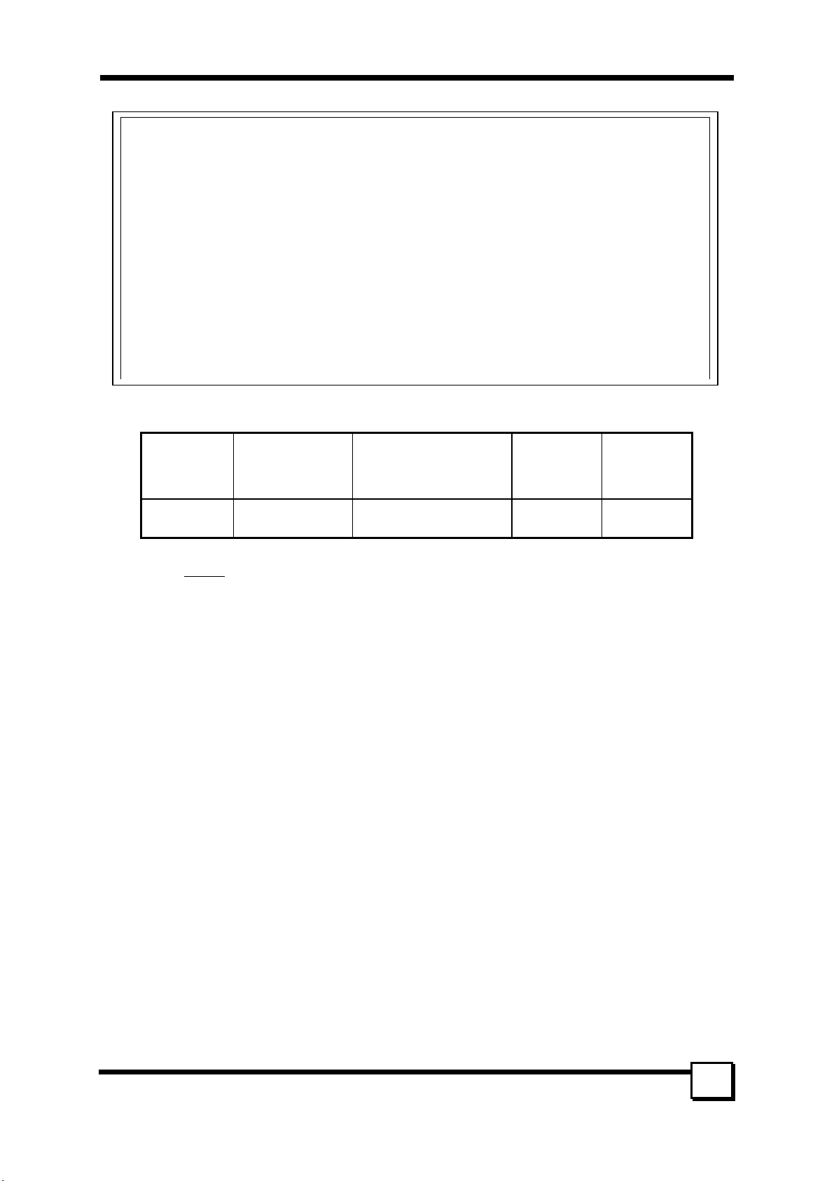
Model
Number
TR-824
The designation TR-824
Protocol PCI Interface
Serial ATA 1.0
Specification
is used throughout this manual in reference to the features of the above model.
PCI 2.3 66MHz/32bit
Max Xfer
Rate
(MB/s)
150 4
* All other product names are trademarks or copyrights of their respective owners.
Max
Devices
TR-824 User’s Manual
1
Page 2
CE Compliance Statement
This equipment has been tested and found to comply with the requirements set up in the council directive
on the approximation of the law of member states relating to the EMC Directive 89/336/EEC, amended by
92/31/EEC & 93/68/EEC. For the evaluation regarding to the electromagnetic compatibility, the following
standards were applied:
* EN 55022:1998 * EN 55024:1998
IEC 61000-4-2: 1995+A1: 1998
IEC 61000-4-3: 1995+A1: 1998
IEC 61000-4-4: 1995
IEC 61000-4-6: 1996
IEC 61000-4-8: 1993
TR-824
Tested to Comply
with CE Standards
For Home or Office Use
2
TR-824 User’s Manual
Page 3

TABLE OF CONTENTS
1. INTRODUCTION ...........................................................................................5
1.1 PRODUCT OVERVIEW......................................................................................................... 5
1.1.1 Specifications:....................................................................................................................................... 5
1.1.2 SATA Raid Features .............................................................................................................................. 5
1.2 RAID EXPLAINED ............................................................................................................. 6
1.2.1 Disk Striping (RAID 0).......................................................................................................................... 6
1.2.2 Disk Mirroring (RAID 1)....................................................................................................................... 6
1.2.3 Combination of RAID 0 and RAID 1 (RAID 0+1) ................................................................................ 6
1.2.4 Data Striping with Striped Parity (RAID 5).......................................................................................... 7
2. HARDWARE SETUP......................................................................................8
2.1 BOARD LAY OU T ................................................................................................................ 8
2.2 INSTALLING TR-824 ..........................................................................................................8
2.3 INSTALLING HARD DRIVES ................................................................................................ 9
3. BIOS CONFIGURATION ..............................................................................10
3.1 BASIC BIOS SCREEN INFORMATION................................................................................. 10
3.2 BIOS FUNCTION.............................................................................................................. 10
3.2.1 Creating RAID Set............................................................................................................................... 10
3.2.2 Deleting RAID Set............................................................................................................................... 10
3.3.3 Rebuilding RAID1 set.......................................................................................................................... 10
3.3.4 Resolving Conflict............................................................................................................................... 10
3.2.5 Low Level Format................................................................................................................................11
3.2.6 Logical Drive Info................................................................................................................................ 11
4. BUILDING DRIVER DISKETTES ...............................................................12
5. INSTALLING SOFTWARE DRIVERS.........................................................13
5.1 WINDOWS SERVER 2003 INSTALLATION ..................................................................... 13
5.1.1 New Windows Server 2003 Installation .............................................................................................. 13
5.1.2 Existing Windows Server 2003 Installation ........................................................................................ 13
5.1.3 Confirming Windows Server 2003 Driver Installation ....................................................................... 13
5.2 WINDOWS XP INSTALLATION .......................................................................................... 13
5.1.1 New Windows XP Installation............................................................................................................. 13
5.1.2 Existing Windows XP Installation....................................................................................................... 14
5.1.3 Confirming Windows XP Driver Installation...................................................................................... 14
5.3 WINDOWS 2000 INSTALLATION ....................................................................................... 14
5.2.1 New Windows 2000 Installation.......................................................................................................... 14
5.2.2 Existing Windows 2000....................................................................................................................... 14
5.2.3 Confirming Windows 2000 Driver Installation................................................................................... 14
5.3 WINDOWS ME INSTALLATION ......................................................................................... 15
5.3.1 New Windows ME Installation............................................................................................................ 15
5.3.2 Existing Windows ME Installation...................................................................................................... 15
5.3.3 Confirming Driver Installation in Windows ME................................................................................. 15
5.4 WINDOWS NT4.0 INSTALLATION ..................................................................................... 15
5.4.1 New Windows NT4.0 Installation........................................................................................................ 15
5.4.2 Existing Windows NT4.0 Installation.................................................................................................. 16
5.4.3 Removing the Driver from Windows NT4.0 ........................................................................................ 16
5.5 WINDOWS 98 INSTALLATION ........................................................................................... 16
5.5.1 New Windows 98 Installation.............................................................................................................. 16
5.5.2 Existing Windows 98 Installation........................................................................................................ 17
5.5.3 Confirming Driver Installation in Windows 98................................................................................... 17
TR-824 User’s Manual
3
Page 4

6. GUI (GRAPHIC USER INTERFACE) ..........................................................18
6.1 GUI INSTALLATION ......................................................................................................... 18
6.2 OVERVIEW....................................................................................................................... 19
6.3 GUI CONFIGURATION MENU ........................................................................................... 23
7. CREATING/NAMING PARTITIONS............................................................28
7.1 WINDOWS 2000/XP/2003 OPERATING SYSTEM............................................................... 28
7.1.1 Initial Window..................................................................................................................................... 29
7.1.2 Creating Partitions.............................................................................................................................. 29
7.2 WINDOWS NT OPERATING SYSTEM ................................................................................. 30
7.3 WINDOWS 98/ME OPERATING SYSTEM............................................................................ 32
8. TROUBLESHOOTING TIPS.........................................................................38
9. TECHNICAL SUPPORT GUIDE ..................................................................39
TECHNICAL SUPPORT SERVICES............................................................................................. 39
Website Support............................................................................................................................................ 39
E-mail Support ............................................................................................................................................. 39
4
TR-824 User’s Manual
Page 5

1. INTRODUCTION
1. INTRODUCTION
1.1 Product Overview
Thank you for purchasing Tekram TR-824 Serial ATA controller card. This controller allows you to install
and enjoy the performance advantage of the new Serial ATA hard drives in your existing PC rather than
spending the time, effort and money in upgrading to a brand-new system. The TR-824 is a four-channel
PCI Serial ATA host adapter that can support up to four Serial ATA drives.
1.1.1 Specifications:
Features
Protocol Supported Serial ATA 1.0 Specification
SATA Processor Sil3114 – Silicon Image PCI to Serial ATA Controller
SATA BIOS Yes (Flash)
Max Transfer Rate Serial ATA Generation 1 transfer rate of 1.5GB/S
PCI Interface PCI 2.3 32 bit data
Max Devices 4
Accessory included z Data Cables – 50cm *4
Drivers Available Windows 98
Supported Devices
1.1.2 SATA Raid Features
• RAID 0, 1, 10
• System GUI Monitoring Utility:
- Displays/Logs/Alerts Users to Vital RAID Set Information
- Manages RAID Set Functions (configures, rebuilds, etc.)
• RAID Set Accommodates Multiple Size HDDs
• HDDs Function Normally When not in RAID Sets
• Adjustable Stripe Size for RAID 0
• Automatically Selects Highest Available Transfer Speed for All ATA and ATAPI Devices
• Supports:
- UDMA up to 150MB/Sec.
- All UDMA and PIO Modes
- ACPI and ATA/ATAPI6
Support RAID 0(striping), RAID 1(mirroring), RAID 10
z Four independent SATA channels
z Support hot-swap and automatically rebuild mirror array
z Easy-to-use GUI-based software for monitoring and storage
management
z Support ATAPI device
z Support driver greater than 137GB
z Power Cables—1pin to 2pin power cable *2
z User’s Manual
z Driver Disk
z GUI software (included in CD)
Windows ME
Windows NT 4.0
Windows 2000
Windows XP
Windows Server 2003
Linux
SATA Devices:
HDD, CD-ROM, CD-RW, DVD-ROM, MO, Tape…etc.
5
TR-824 User’s Manual
Page 6
1. INTRODUCTION
1.2 RAID Explained
RAID - Redundant Array of Independent Disks
RAID technology manages multiple disk drives to enhance I/O performance and provide redundancy in
order to withstand the failure of any individual member, without loss of data.
SATA Raid provides four popular RAID Set types, Striped (RAID 0), Mirrored (RAID 1), a combination of
RAID 0 and RAID 1 (RAID 0+1), and Data Striping with Striped Parity (RAID 5) which will be supported
by Tekram next generation SATA products.
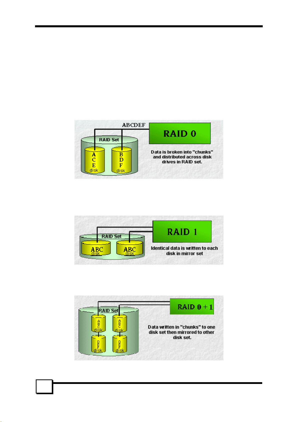
1.2.1 Disk Striping (RAID 0)
RAID 0 is a performance-oriented, non-redundant data mapping technique. While Striping is discussed as a
RAID Set type, it actually does not provide fault tolerance. With modern SATA and ATA bus mastering
technology, multiple I/O operations can be done in parallel, enhancing performance. Striping arrays use
multiple disks to form a larger virtual disk.
1.2.2 Disk Mirroring (RAID 1)
RAID 1 mirrors one disk drive to another. All data is stored twice on two or more identical disk drives.
When one disk drive fails, all data is immediately available on the other without any impact on the data
integrity – performance in degraded mode is also degraded. If multiple read requests are pending, the
RAID controller will allow reading from different disk drives.
1.2.3 Combination of RAID 0 and RAID 1 (RAID 0+1)
The idea behind RAID 0+1 is simply based on the combination of RAID 0 (Performance) and RAID 1
(Data Security). RAID 0+1 disk sets offer good performance and data security. Similar as in RAID 0,
optimum performance is achieved in highly sequential load situations.
6
TR-824 User’s Manual
Page 7
1. INTRODUCTION
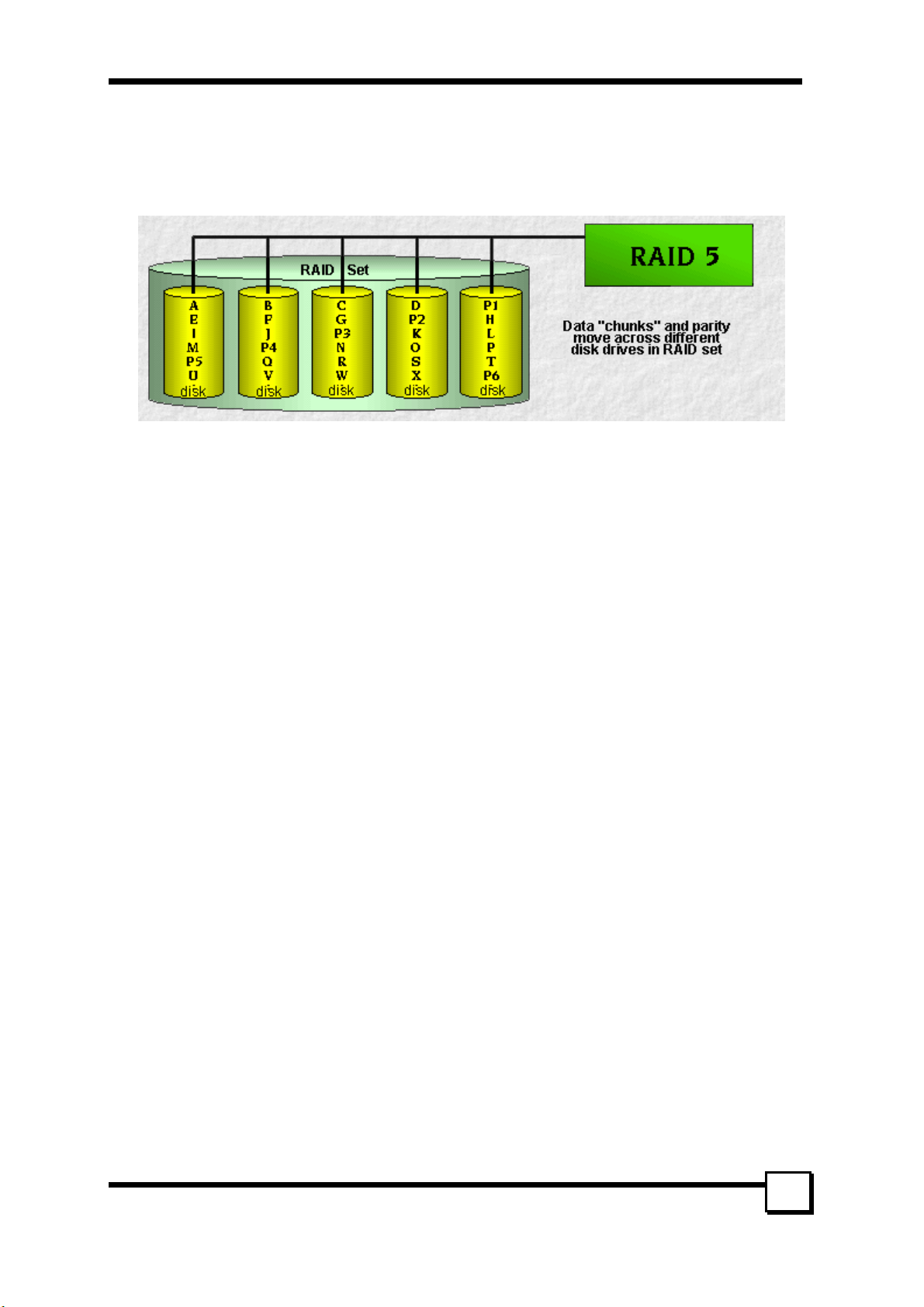
1.2.4 Data Striping with Striped Parity (RAID 5)
The data is striped across disk drives. The parity data in a RAID 5 set is striped across all disk drives.
RAID 5 is designed to handle small data blocks. This makes RAID 5 an excellent choice for multitasking,
multi-user and database environments. The security provided by RAID 5 is that when one disk drive fails,
all data is fully available, the missing data is recalculated from the data that is still available and the parity
information. This data calculation can also be used to restore data to replaced defective disks.
TR-824 User’s Manual
7
Page 8
2. HARDWARE SETUP
2. HARDWARE SETUP
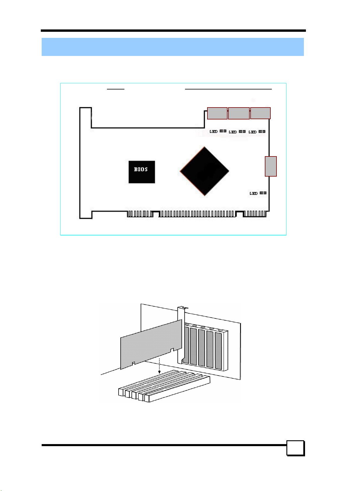
2.1 Board Layout
The following figures illustrate the chip and connector locations for the TR-824 PCI SATA Host Adapter.
TR-824 Serial ATA 4-channel Host Adapter
7-pin Serial ATA connector
S
Sil3114
2.2 Installing TR-824
The TR-824 Controller card fits into any available 32-bit PCI slot (must be PCI 2.2 or 2.3 compliant). It
also fits the 32-bit portion of a 64-bit PCI slot, on the system’s motherboard (see figure below).
1. Remove the cover of your system.
2. Remove the inside slot cover of an available PCI slot on the motherboard.
3. Install the TR-824 Controller card into the open slot. Secure the bracket to the system’s frame.
4. Fasten the controller card bracket to the system case (see below).
TR-824 User’s Manual
8
Page 9

2. HARDWARE SETUP
2.3 Installing Hard Drives
The TR-824 Controller card supports up to four Serial ATA hard drives. Install all of the hard drives into
the hard drive bays of your system, including their power cables.
Attach one Serial ATA data cable to each hard drive. Then attach the other ends of the cables to one of the
Serial ATA ports on the TR-824 card. All of the connectors are keyed so they can only be attached one
way.
Note: The TR-824 Controller card is a PCI Plug-n-Play (PnP) device. No changes are necessary in
the Motherboard CMOS Setup for resources or drive types in most applications.
TR-824 User’s Manual
9
Page 10

3. BIOS CONFIGURATION
3. BIOS CONFIGURATION
3.1 Basic BIOS screen information
After you install the TR-824 RAID Controller and HDDs in your computer and boot your system, you will
see the screen that displays information about the card and HDDs installed. Press <CTRL-S> or F4 to enter
RAID utility. An easy-to-use screen will appear with the following choices on the top left
Create RAID Set
Delete RAID Set
Rebuild RAID1 Set
Resolve Conflicts
Low level Format
Logical Drive Info
The top right half shows direction and guiding information.
The bottom left half of the screen displays the information of physical drives. The bottom right half lists
logical drives’ information.
There are the command keys:
Arrows up and down are Select Keys
ESC takes the user to the previous menu
Enter selects the user’s choice
Ctrl-E exits the utility
3.2 BIOS Function
3.2.1 Creating RAID Set
1. Select “Create RAID Set.”
2. Choose from the list of “RAID 0”, “RAID 1”, RAID 10” and “SPARE DRIVE”.
3. If the “RAID 0” is chosen, the utility will ask you to select how many drives for the raid0 set. You can
choose from the list of numbers which is according to how many drives are connected to the computer.
Then you can choose from Auto Configuration and Manual Configuration. Finally, the utility will ask
“Are You Sure?” before completing the configuration.
4. If you select the second or third option, you’ll be asked to choose from Auto Configuration and
Manual Configuration. Finally, the utility will ask “Are You Sure?” before completing the
configuration. Afterward the utility will ask “Are You Sure?” before completing the configuration.
5. If the RAID 1 set has already been built, you can choose “SPARE DRIVE” to set a hot spare drive as a
backup for the existing RAID 1. The utility will ask “Are You Sure?” before completing the
configuration.
3.2.2 Deleting RAID Set
1. To remove one or more RAID sets, select “Delete RAID Set.”
2. Select desired set and press Y when asked “Are You Sure?”
3.3.3 Rebuilding RAID1 set
If a hard disk is damaged when running RAID 1, remove the damaged HDD, connect a workable one,
rebuild the array and restore data by selecting Rebuild Mirrored set. This can be done either online or
offline.
3.3.4 Resolving Conflict
When a RAID set is created, the metadata written to the disk includes drive connection information
(Primary Channel, Secondary Channel). If, after a disk failure, the replacement disk was previously part of
a RAID set (or used in another system), it may have conflicting metadata, specifically in reference to the
drive connection information. If so, this will prohibit the RAID set from being either created or rebuilt, In
order for the RAID set to function properly; this old metadata must be first overwritten with the new
metadata. To resolve this, select “Resolve Conflict” and the correct metadata, including the correct drive
connection information; will be written to the replacement disk.
TR-824 User’s Manual
10
Page 11

3. BIOS CONFIGURATION
3.2.5 Low Level Format
When any of the drives fails to normally function or there is any logical error in one of the drives, you can
select “Low Level Format” to resolve the problem by reverting the drive to original condition.
3.2.6 Logical Drive Info
The complete information about the logical drives will be shown on the bottom right part of the screen if
this option is chosen.
TR-824 User’s Manual
11
Page 12

4. BUILDING DRIVER DISKETTES
4. BUILDING DRIVER DISKETTES
If you do not have the Driver Diskettes, you can create them from the Driver CD. Follow these steps to
create the Driver Diskettes.
1. The system BIOS must set to boot from a CD-ROM.
2. Insert the Driver CD into the CD-ROM drive. Start the driver building by booting from the CD-ROM.
Tekram SATA Adapters Driver Diskette Make Utility starts and provides several screens with
choices. Follow the steps below to correctly set up the device driver for separate operating system.
3. After the Screen appears, move the highlight bar to the TR-824 entry and press <Enter>.
4. The next screen queries the TR-824 support driver database and a list of supported driver is displayed.
Move the highlight bar to the driver entry and press <Enter>.
5. The next screen will show “Please insert a formatted diskette into drive A:\!! Press any key to
continue. ” Insert the formatted diskette in drive A:\ and press any key to continue.
6. The next window displays the driver-building message, “Now is writing to Cylinder and copy the
image file from the CD-ROM to Driver Diskette.”
7. “The Write Complete!!” Message will show on the screen when the driver is built.
TR-824 User’s Manual
12
Page 13

5. INSTALLING SOFTWARE DRIVERS
5. INSTALLING SOFTWARE DRIVERS
5.1 Windows Server 2003 Installation
5.1.1 New Windows Server 2003 Installation
The following details the installation of the TR-824 drivers while Installing Windows 2003.
1. Start the installation:
• Floppy Install: Boot the computer with the Windows Server 2003 installation diskettes.
• CD-ROM Install: Boot from the CD-ROM. Press <F6> when the message “Press F6 if you need to
install third party SCSI or RAID driver” appears.
2. When the Windows Server 2003 Setup window is generated, press <S> to specify an Additional
Device(s)
3. Insert the TR-824 driver diskette into drive A:\ and press <Enter>.
4. Choose Tekram TR-824 SATARaid Controller for Windows XP/ Server 2003 from the list that
appears on screen, and then press <Enter>.
5. The Windows Server 2003 Setup screen will appear “Setup will load support for the following mass
storage devices:”. The list will include Tekram TR-824 SATARaid Controller for Windows XP/
Server 2003.
NOTE: If there are any additional devices to be installed, specify them now. When all devices are
specified, continue to the next step.
7. From the Windows Server 2003 Setup screen, press <Enter>. Setup will now load all device files and
then continue the Windows Server 2003 installation.
5.1.2 Existing Windows Server 2003 Installation
After installing the TR-824 card and rebooting your system, Windows Server 2003 setup will show a
Found New Hardware dialog box. Under Windows Server 2003, “RAID Controller” will be displayed.
1. Insert the TR-824 driver diskette into the drive A:\.
2. Choose install from a list or specific location and specify to search removable media then press
<Enter>.
3. Choose Tekram TR-824 SATARaid Controller from the list that appears on screen, and then press the
4. If using a driver that has not been digitally signed by Microsoft, you will be asked if you want to
5. When the New Hardware Wizard has finished installing the TR-824 software, click Finish.
5.1.3 Confirming Windows Server 2003 Driver Installation
1. Right-click the My Computer icon and select Manage from the popup menu.
2. Click Device Manager in the menu tree.
3. Click the “+” in front of SCSI controllers. “Tekram TR-824 SATARaid Controller” should appear.
5.2 Windows XP Installation
5.1.1 New Windows XP Installation
The following details the installation of the TR-824 drivers while Installing Windows XP.
1. Start the installation:
2. When the Windows XP Setup window is generated, press <S> to specify an Additional Device(s)
3. Insert the TR-824 driver diskette into drive A:\ and press <Enter>.
4. Choose Tekram TR-824 SATARaid Controller for Windows XP/ Server 2003 from the list that
5. The Windows XP Setup screen will appear “Setup will load support for the following mass storage
NOTE: If there are any additional devices to be installed, specify them now. When all devices are
<Enter> key.
continue the installation. Click Continue.
• Floppy Install: Boot the computer with the Windows XP installation diskettes.
• CD-ROM Install: Boot from the CD-ROM. Press <F6> when the message “Press F6 if you need to
install third party SCSI or RAID driver” appears.
appears on screen, and then press <Enter>.
devices:”. The list will include Tekram TR-824 SATARaid Controller for Windows XP/ Server
2003.
13
TR-824 User’s Manual
Page 14

5. INSTALLING SOFTWARE DRIVERS
specified, continue to the next step.
7. From the Windows XP Setup screen, press <Enter>. Setup will now load all device files and then
continue the Windows XP installation.
5.1.2 Existing Windows XP Installation
After installing the TR-824 card and rebooting your system, Windows XP setup will show a Found New
Hardware dialog box. Under Windows XP, “RAID Controller” will be displayed.
1. Insert the TR-824 driver diskette into the drive A:\.
2. Choose install from a list or specific location and specify to search removable media then press
<Enter>.
3. Choose Tekram TR-824 SATARaid Controller from the list that appears on screen, and then press the
4. If using a driver that has not been digitally signed by Microsoft, you will be asked if you want to
5. When the New Hardware Wizard has finished installing the TR-824 software, click Finish.
5.1.3 Confirming Windows XP Driver Installation
1. Right-click the My Computer icon and select Manage from the popup menu.
2. Click Device Manager in the menu tree.
3. Click the “+” in front of SCSI controllers. “Tekram TR-824 SATARaid Controller” should appear.
5.3 Windows 2000 Installation
5.2.1 New Windows 2000 Installation
The following details the installation of the TR-824 drivers while installing Windows 2000.
1. Start the installation:
2. When the Windows 2000 Setup window is generated, press <S> to specify an additional device(s).
3. Insert the TR-824 driver diskette into drive A:\ and press <Enter>.
4. Choose Tekram TR-824 SATARaid Controller for Windows NT 4.0 and 2000 from the list that
5. The Windows 2000 Setup window will appear again saying, “Setup will load support for the
NOTE: If there are any additional devices to be installed, specify them now. When all devices are
specified, continue to the next step.
6. From the Windows 2000 Setup screen, press <Enter>. Setup will now load all device files and then
5.2.2 Existing Windows 2000
After installing TR-824 card and rebooting your system, Windows 2000 setup will show a New Hardware
Found dialog box. Under Windows 2000, “RAID Controller” will be displayed.
1. Insert the TR-824 driver diskette in drive A:\.
2. Choose Search for a suitable driver for my device (Recommended) from the list, then click Next.
3. Choose Floppy disk drives from the list, then click Next. The Hardware Wizard will search the
4. Click Next. The Found New Hardware Wizard appears when the installation is completed.
5. Remove the diskette and click Finish to restart the system. Windows 2000 will then restart for the driver
5.2.3 Confirming Windows 2000 Driver Installation
1. Right-click the My Computer icon and select Manage from the popup menu.
2. Click Device Manager in the menu tree.
<Enter> key.
continue the installation. Click Continue.
• Floppy Install: Boot the computer with the Windows 2000 installation diskettes.
• CD-ROM Install: Boot from the CD-ROM. Press <F6> when the message “Press F6 if you need to
install third party SCSI or RAID driver” appears.
appears on screen then press <Enter>.
following mass storage devices:”. The list will include TR-824 SATARaid Controller for Windows
NT 4.0 and 2000.
continue the Windows 2000 installation.
diskette for updates and return the following message “Windows found a driver for this device.
A:\tr824.inf. To install the driver Windows found, click Next”.
installation to take effect.
14
TR-824 User’s Manual
Page 15

5. INSTALLING SOFTWARE DRIVERS)
3. Click the “+” in front of SCSI controllers. “Tekram TR-824 SATARaid Controller” should appear.
5.3 Windows ME Installation
5.3.1 New Windows ME Installation
The following details the installation of the TR-824 drivers while installing Windows ME.
1. Install the TR-824 controller card into your system.
2. Install Windows ME fully.
3. After installation, right-click on My Computer and select Properties from the popup menu.
4. In the System window, choose the Device Manager tab.
5. In the hierarchical display under Other Devices is a listing for PCI RAID Controller. Click PCI RAID
Controller then click Properties.
6. In the Properties window, choose the Driver tab then choose Update Driver and click Next.
7. Choose “Search for a better driver than the one your device is using now (recommended)” then click
Next.
8. Choose Specify Location then type “A:\tr824.inf” in the text box.
9. Insert the TR-824 driver diskette into the A:\ drive.
10. Click the Next button. A message informing you that “Tekram TR-824 SATARaid Controller”
should appear.
11. Click Next, then click Finish.
12. When asked if you want to restart your computer, click Yes. Immediately remove the diskette from
drive A:\.
5.3.2 Existing Windows ME Installation
The following section details the installation of TR-824 drivers on a system that has Windows ME already
installed and running.
1. After installing the TR-824 controller card and configuring the hard drives, power up the system and
boot.
2. The Add New Hardware Wizard will appear, informing you that it has found a PCI Mass Storage
Controller.
3. Click Next, then from the generated list box, choose Specify the location of the driver (Advanced).
4. Click Next, then from the generated choices, choose Specify a location.
5. Insert the TR-824 driver diskette in drive A:\.
6. Type “A:\tr824.inf” in the text box that appears.
7. Click Next. A message informing you that Windows Me has found “Tekram TR-824 SATARaid
Controller” should appear.
8. Click Next, then click Finish. When asked if you want to restart your computer, click Yes. Immediately
remove the diskette from drive A:\.
5.3.3 Confirming Driver Installation in Windows ME
To confirm that the driver has been properly loaded in Windows Me, perform the following steps:
1. Right-click the My Computer icon and select Properties from the popup menu.
2. Select the Device Manager tab.
3. Click the “+” in front of SCSI controllers. “Tekram TR-824 SATARaid Controller” should appear.
5.4 Windows NT4.0 Installation
5.4.1 New Windows NT4.0 Installation
The following details the installation of the TR-824 drivers while installing Windows NT4.0.
1. Start the system installation by booting from the Windows NT disk:
Floppy install: boot the system with the Windows NT installation diskettes.
CD-ROM disk install: boot from the CD-ROM disk and press <F6> when the message “Setup is
inspecting your computer’s hardware configuration…” appears.
2. When the Windows NT Setup window is generated, press <S> to Specify an Additional Device(s).
3. Select Other then press <Enter>.
4. Insert the TR-824 driver diskette into drive A:\ and press <Enter>.
5. Choose Tekram TR-824 SATARaid Controller for Windows NT 4.0 and 2000 from the list that
TR-824 User’s Manual
15
Page 16

5. INSTALLING SOFTWARE DRIVERS
appears on screen then press <Enter>.
6. The Windows NT Setup window will appear again saying, “Setup will load support for the following
mass storage devices:” The list will include TR-824 SATARaid Controller for Windows NT 4.0 and
2000
NOTE: If there are any additional devices to be installed, specify them now. When all devices are
specified, continue to the next step.
7. From the Windows NT Setup screen, press <Enter>. Setup will now load all device files and then
continue the Windows NT installation.
8. After a successful installation, the SCSI Adapter Setup box will show that “the Tekram TR-824
SATARaid Controller driver has been installed”.
5.4.2 Existing Windows NT4.0 Installation
The following section details the installation of TR-824 drivers on a system that has Windows NT4.0
already installed and running.
NOTE: Do not attach the boot drive or any other hard drive to the TR-824 controller card before
completing this step.
1. From the Start menu, choose Settings.
2. From the Settings menu, choose Control Panel.
3. Double-click the SCSI Adapters icon. The SCSI Adapters dialog box appears.
4. Choose Drivers then click Add.
5. In the Install Drivers dialog box, click Have Disk….
6. When Install From Disk appears, insert the TR-824 driver diskette in drive A:\.
7. Type “A:\tr824.inf” in the text box window then click OK.
8. When the Install Driver dialog box appears, select Tekram TR-824 SATARaid Controller then click
OK.
9. When the Select SCSI Adapter Option dialog box appears, click Install.
10. After a successful installation, the SCSI Adapter Setup box will show that “the Tekram TR-824
SATARaid Controller has been installed”.
11. Power off your system.
12. If you plan to move the boot drive to the TR-824 card, connect the boot drive to the card now. Then
power on your system.
5.4.3 Removing the Driver from Windows NT4.0
1. From Start, choose Setup then choose Control Panel.
2. In Control Panel, choose SCSI Adapter then choose Drivers.
3. Click Remove.
4. After successful removal, the SCSI Adapter Setup box will show that “the Tekram TR-824
SATARaid Controller has been removed”.
5.5 Windows 98 Installation
5.5.1 New Windows 98 Installation
The following section details the installation of the TR-824 drivers while installing Windows 98.
1. Install the TR-824 controller card and configure the hard drive(s), partition and format your hard
drive(s), if necessary.
2. Install Windows 98 normally.
3. After installation, generate the Start menu and choose Settings.
4. From the Settings menu, choose Control Panel.
5. In the Control Panel window, double-click the System icon.
6. In the System window, choose the Device Manager tab.
7. In the hierarchical display under Other Device is a listing for PCI RAID Controller. Select it then click
the Properties button.
8. Choose the Driver tab in the Properties window, choose Update Driver then click
Next.
9.Choose Search for a better driver than the one your device is using now (recommended), then click
16
TR-824 User’s Manual
Page 17

5. INSTALLING SOFTWARE DRIVERS)
Next.
10. Choose Specify Location then type “A:\tr824.inf” in the text box.
11. Insert the TR-824 driver diskette into the A:\ drive.
12. Click the Next button. A message informing you “Windows 98 has found Tekram TR-824
SATARaid Controller” should appear.
13. Click Next, then Finish.
14. When asked if you want to restart your computer, click Yes. Immediately remove the diskette from
drive A:\.
5.5.2 Existing Windows 98 Installation
The following section details the installation of TR-824 drivers on a system that has Windows 98 already
installed and running.
1. After installing the TR-824 controller card and configuring the hard drives, power up the system and
boot Windows.
2. The Add New Hardware Wizard will appear, informing you that it has found a PCI Mass Storage
Controller.
3. Click Next. From the generated list box, choose Search for best driver for your device (Recommended).
4. Insert the TR-824 driver diskette in drive A:\.
5. Click Next. From the generated choices, choose Specify a location.
6. Type “A:\tr824.inf” in the text box that appears.
7. Click Next. A message informing you that “Windows 98 has found Tekram TR-824 SATARaid
Controller” should appear.
8. Click Next, then click Finish.
9. Click Yes when asked if you want to restart your computer. Be sure to eject the diskette from drive A:\.
5.5.3 Confirming Driver Installation in Windows 98
To confirm that the driver has been properly loaded in Windows 98, perform the following steps:
1. Choose Settings from the Start menu.
2. Choose Control Panel, then double-click the System icon.
3. Choose the Device Manager tab, then click the “+” in front of SCSI controllers. “Tekram TR-824
SATARaid Controller” should appear.
TR-824 User’s Manual
17
Page 18

6. GUI (GRAPHIC USER INTERFACE)
6. GUI (GRAPHIC USER INTERFACE)
GUI stands for Graphic User Interface, the GUI function offers user-friendly graphics in Windows
operating systems for easy RAID array monitoring and storage management. After you install the TR-824
SATA RAID card and HDDs, create RAID arrays in BIOS configuration, execute ‘FDISK’ and ‘format’
command in DOS mode and install drivers for your operating system, you can take the following steps to
install the GUI in Windows operating systems and execute GUI functions.
6.1 GUI Installation
You’d better set your screen display resolution rate as 800X600 or 1024X768 to avoid display abnormality
during GUI setup.
1. After you power on your computer and bootup Windows, insert the CD into disk drive
2. Double-click on jre.exe under GUI directory to install Java 2 Runtime Environment. If you’re
installing on a non-English OS, better choose Custom installation to specify program features. Always
select the second option in the dropdown menu.
3. Double-click on Java SATARaid.exe under the GUI directory after the Java2 platform installation.
4. Follow on-screen instructions to complete installation.
Note: Do NOT install in the Start Up folder. Choose the Default folder (normally Accessories or
Administrative Tools or something similar).
18
TR-824 User’s Manual
Page 19
6. GUI (GRAPHIC USER INTERFACE)
d
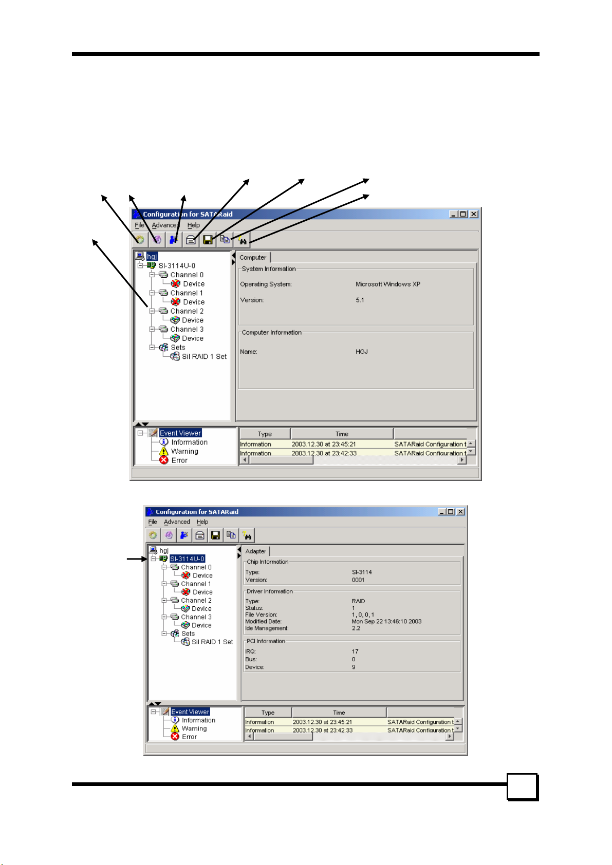
6.2 Overview
The SATA Raid GUI offers the user the ability to easily monitor your RAID Set.
To launch the GUI, simply double-click on the icon located in the bottom right hand corner of the Desktop.
If the icon does not appear in the bottom right hand corner of the desktop, find where the application was
saved and launch from there.
Upon launching the GUI, the first window, which identifies the computer running SATARaid, should
appear similar to the following:
RAID
Management
Configuration
tree
System
Vie w
Configure
SATARai
Send
Configuration
Save Configuration
Copy configuration
SATARaid Help
Selecting each different component in the configuration tree provides specific information for that
component, such as the chip.
TR-824 User’s Manual
19
Page 20

6. GUI (GRAPHIC USER INTERFACE)
Selecting any specific channel from the four channels, the following information is reported:
Selecting a specific drive reports all relevant information to that drive, including Configuration and Disk
Identification information.
20
TR-824 User’s Manual
Page 21

6. GUI (GRAPHIC USER INTERFACE)
Selecting Sets lists the Sets in the configuration tree and provides information on RIO Version:
By selecting a specific RAID set, such as Set 1, the type of RAID set, the number of members and capacity
is reported.
The Members tab of this window reports the device identification (corresponding with the information in
the BIOS) and the State of each device.
Besides reporting information, the Members tab of a Mirrored set allows the user to remove a specific
TR-824 User’s Manual
21
Page 22

6. GUI (GRAPHIC USER INTERFACE)
drive from that set, as well as add a designated Spare drive to a Mirrored set that has experienced a disk
failure. A drive can NOT be removed from a Striped set as this would destroy all data. Note that when a
Mirrored Set is first created, the State of the “destination” drive may report as Rebuild for as much as
30-90 minutes depending on the size of the disk.
The Device Location refers
to how each physical disk
was reported in the BIOS
RAID utility
SMART and Configuration information, as well as Data Identification are again provided for each Set.
22
TR-824 User’s Manual
Page 23

6. GUI (GRAPHIC USER INTERFACE)
6.3 GUI Configuration Menu
By clicking on the toolbox icon in the top left of the SATA Raid GUI window, or right-clicking on the
conductor icon in the bottom right of the computer screen (with other start-up icons), the user may
configure SATA Raid including customizing the settings for SMTP, E-mail, Notification, Event Level, Log
File, Audio, and Popup.
SMTP
The SMTP server is the server that is used to send e-mails. Normally, the network administrator knows
what this name is. Both the name and domain must be entered.
TR-824 User’s Manual
23
Page 24

6. GUI (GRAPHIC USER INTERFACE)
E-Mail
The current SATARaid configuration may be sent via e-mail. Using the e-mail tab in the SATARaid
Configuration Menu, the user may set the default e-mail address and subject line where the configuration
would be sent. This, however, can be overridden at the time of sending the email.
Notification
When different types of events occur, SATARaid may be configured to send notices to assigned individual
e-mail addresses. Using the Notification tab, all e-mail addresses desired to receive the notices may be
entered.
24
TR-824 User’s Manual
Page 25

6. GUI (GRAPHIC USER INTERFACE)
Event Level
There are different types of e-mail notifications
that may be sent which are set with the Event
Level tab. The different levels are:
Disable - No event logs will be sent.
Information - The following events will be sent:
- Information
- Warn in gs
- Errors
Warning - The following events will be sent:
- Warn in gs
- Errors
Error - The following events will be sent:
- Errors
Log File
The log file is used to store event information received from all the Silicon Image RAID drivers. The log
file is a text file and can be viewed with Notepad or SATARaid. Use the Log File tab to set where the log
file should be stored and the name of the file as well.
TR-824 User’s Manual
25
Page 26

6. GUI (GRAPHIC USER INTERFACE)
Audio
The user may set different audio alerts for the different levels of events.
Popup
The popup window is a visual notification that an
event occurred. The popup window can be disabled
or set to popup for only certain event levels. The
different levels are:
Disable - No popup will occur.
Information - The popup window will be Displayed
for the following events:
- Information
- Warn in gs
- Errors
Warning - The popup window will be displayed for
the following events:
- Warn in gs
- Errors
Error - The popup window will be displayed for the
following events
- Errors
26
TR-824 User’s Manual
Page 27

6. GUI (GRAPHIC USER INTERFACE)
TrayIcon
There are different levels of events that tray icon
may blink for. The different levels are:
Disable – The tray icon will blink for no event.
Information - The tray icon will blink for the
following events:
- Information
- Warn in gs
- Errors
Warning - The tray icon will blink for the following
events:
- Warn in gs
- Errors
Error – The tray icon will blink for the following
event:
- Errors
Event Table
There are different levels of events that may be
Shown in the event table:
Disable – No event will be shown in the event table.
Information - The event table will show the following
events:
- Information
- Warn in gs
- Errors
Warning - The event table will show the following
events:
- Warn in gs
- Errors
Error – The event table will show the following
event:
- Errors
Event Time
You can set a proper fixed time interval when the
System will monitor the controller.
TR-824 User’s Manual
27
Page 28
7. CREATING/NAMING PARTITIONS
7. CREATING/NAMING PARTITIONS
The creating and naming of partitions is something done within the Windows operating system. And while
Windows 2000/XP/2003 and Windows NT both use the Disk Management window, there are enough
nuances that make it important to follow the procedure specifically for the appropriate operating system.
The procedure for Windows 98/Me is significantly different from the others.
7.1 Windows 2000/XP/2003 Operating System
Before creating any partitions, RAID sets must first be created/dissolved using the BIOS RAID Utility.
Once completed, continue booting Windows.
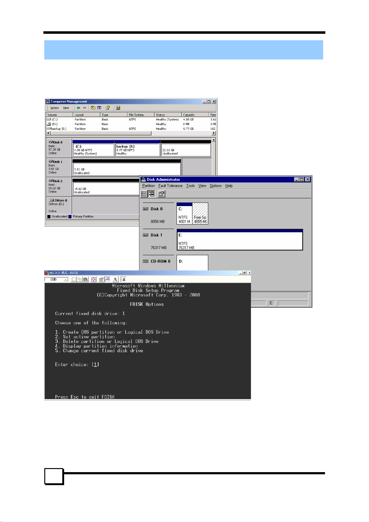
Once Windows is running, open the Disk Management window located at: Control Panel --Administrative
Tools--Computer Management--Storage Disk Management
Something similar to the following window should appear:
28
TR-824 User’s Manual
Page 29

7. CREATING/NAMING PARTITIONS
SECTION 1
SECTION 2
SECTION 3
This window has three main sections:
SECTION 1: System listing of all formatted and available disks/RAID Sets.
SECTION 2: Report of physical connection of disks/RAID Sets.
SECTION 3: Report of partition status, disk letter, and volume name.
7.1.1 Initial Window
In SECTION 2, every disk should report as:
Basic
Disk Size (the actual available disk space will be reported here)
Online
Instead of “Basic,” a disk may also report as either “Unknown” or “Dynamic.”
If the disk reports as “Unknown”, right-click on the disk (SECTION 2) and click on Write Signature.
At this point, a window will appear with the disk in question (all “Unknown” disks may appear in this
window). Make sure the box next to each disk is checked, and then click OK.
The disk should now report as “Basic.”
If a disk reports as “Dynamic,” right-click on SECTION 2 of that disk, and click on “Return disk to
Basic...” Within seconds the disk should report as Basic.
7.1.2 Creating Partitions
In SECTION 2, the disk order corresponds directly to the order the Sets appear in the BIOS. Therefore,
the first Unallocated Partition represents Set 1, and so on.
1. At this point, there should be three disks with Unallocated partitions. Right-click on the partition of the
first disk and click on “Create Partition.” The “Create Partition Wizard” should appear.
1. The first window is an introductory window to the Wizard. Click Next.
2. The second window designates the partition as a primary partition. Click Next.
3. The third window designates the partition size. Since this is a Striped RAID set, utilizing 2 disk
drives, the size of the partition should be approximately double the size of a single disk drive
(assuming all disks are of identical size). Click Next.
4. The fourth window designates the drive letter of the partition.
5. The fifth window allows the user to label the volume name, and choose the type of formatting to
take place upon the creation of the partition. Choose whichever drive letter is desired (the lowest
TR-824 User’s Manual
29
Page 30

7. CREATING/NAMING PARTITIONS
possible value is automatically entered), name the volume whatever is desired (suggestions being
something generic such as STRIPED SET or something specific to use such as FINANCIAL,
CRITICAL, MISCELLANEOUS, etc.) then check the box next to “quick format.” Click Next.
6. The sixth window is a summary window listing all of the selections made. Click Finish.
Depending on the size of the disk drive(s) included in the partition, the partition should change from
“Unallocated” to “Healthy” with its name and drive letter reported as well in a matter of minutes or less.
Do not attempt to create a partition for the next disk until the disk currently being formatted is complete
and reports Healthy.
Also note that once the disk reports Healthy, it appears in the listing in SECTION 1 with all of its pertinent
information as well.
2. Repeat this procedure for the partition of the second and third disk.
3. Close the Data Management window by clicking on the small boxed “X” in the top right corner of the
window.
4. Click on the “My Computer” icon on the Desktop. The three new drives should now be visible and
properly named. Data may now be stored to each of these disks if desired.
7.2 Windows NT Operating System
Before creating any partitions, RAID sets must first be created/dissolved using the BIOS RAID Utility.
Once completed, continue booting Windows.
Once Windows is running, open the Disk Administrator window. The Disk Administrator window is
located at: Start Programs Disk Administrator (Common)
Something similar to the following window should appear:
30
TR-824 User’s Manual
Page 31
7. CREATING/NAMING PARTITIONS
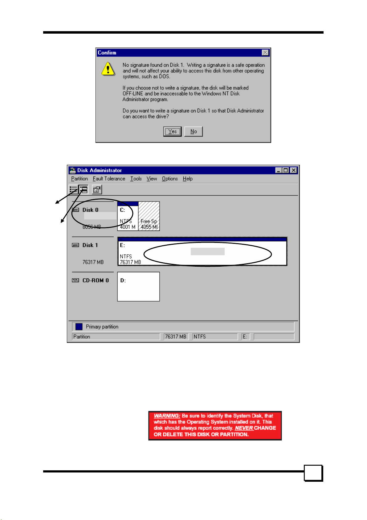
However, this Write Signature window may appear first:
If so, answer YES for each disk reported with no signature found. Afterwards, something similar to the
following should appear:
Button 1
Button 2
SECTION 1
SECTION 2
Button 1 opens the Disk Administrator Volumes window, which lists the recognizable Volumes, their
capacity, free space, type of format, etc.
Button 2 opens the Disk Configuration window (shown above), detailing all disks (or RAID Sets),
partitions, and allows the user to format and name each partition and volume.
Section 1 reports the size of each disk (or RAID Set).
Section 2 reports on each partition, and allows the user to format or delete partitions.
Creating Partitions
1. If any disk (besides the SYSTEM
DISK) appears to be formatted,
right click on that partition
(Section 2) and select Delete.
2. Once all disks are reported as Free Space, right-click on each partition and select Create...
3. A Create Primary Partition window should now appear. Click OK.
TR-824 User’s Manual
31
Page 32

7. CREATING/NAMING PARTITIONS
4. Click Confirm.
5. Repeat this step for each disk.
6. Now, right-click on the first disk and select Mark Active.
7. A window will appear stating that this will take place on the next reboot. Click OK.
8. Repeat this step for each disk.
9. Close window. Confirm saving changes. Click Yes .
10. Disk Administrator will report that the disks were updated successfully. Click OK.
11. Re-open Disk Administrator.
12. Right-click on the first disk (this should now be the Striped Set).
13. Select Format...
Something similar to the following window should appear:
14. While Capacity cannot be changed, make sure that File System has NTFS selected, don’t change
Default Allocation Size, and since it is the Striped Set that is being formatted, enter Striped Set for
Vol u m e L a be l. Make sure that Quick Format is selected as the Format Option.
15. Repeat this procedure for the other two disks, but name them something else.
16. Close Disk Administrator and open My Computer (icon should be on Desktop).
17. The new disks should now appear in My Computer window.
18. Close all windows and applications and Restart computer.
7.3 Windows 98/Me Operating System
Windows 9x does not have a Disk Administrator or Disk Management window. Instead, after creating
RAID sets using the BIOS RAID utility and booting Windows, start fdisk by:
1. Click on the START button
2. Select Run...
3. Type fdisk
4. Click OK
The following window will probably appear:
32
TR-824 User’s Manual
Page 33

7. CREATING/NAMING PARTITIONS
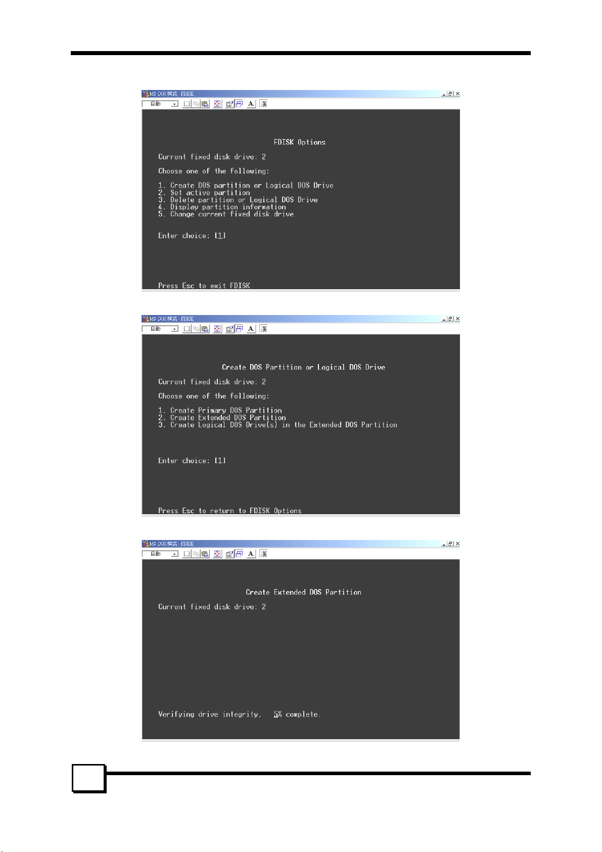
Press Enter for yes. The FDISK Options window will appear:
The Current Fixed Drive will be the System Drive (normally C:\). In order to create partitions, the fixed
drive needs to be changed. Select 5 and press Enter.
TR-824 User’s Manual
33
Page 34
7. CREATING/NAMING PARTITIONS
Enter the disk number to partition and press Enter.
With the Current fixed drive set at the disk needing to be partitioned, Select 1 and press Enter.
The following window will appear:
Select 2 to create an extended partition and press Enter. The following window will appear:
34
TR-824 User’s Manual
Page 35

7. CREATING/NAMING PARTITIONS
Once the percentage counter reaches 100%, the following window will appear:
This window explains how much space will be available in the partition. Press Enter.
This window shows that the partition has been created. Press Esc.
FDISK is now creating a logical drive.
TR-824 User’s Manual
35
Page 36

7. CREATING/NAMING PARTITIONS
Once the percentage counter reaches 100% the following window appears:
Once again, this window reports size.
Press Enter and the following window appears:
This window now shows the drive and its drive letter and size. Press Esc.
If another drive (RAID set) needs to be partitioned, repeat the process, starting by changing the fixed disk
drive (Press 5). If done, press Esc.
36
TR-824 User’s Manual
Page 37

The following window will appear:
7. CREATING/NAMING PARTITIONS
This window is a reminder to RESTART the computer.
After restarting the computer, and booting Windows 9x, double-click on the My Computer icon.
Right-click on each new drive and select Format.
Only a FULL format will be accepted at this point. Select Full Format, enter the Label Name for the drive
or RAID set (if desired) and click OK.
Once the drive has been formatted, repeat for each new drive. The new drives should now be ready to be
used.
TR-824 User’s Manual
37
Page 38

8. TROUBLESHOOTING TIPS
8. TROUBLESHOOTING TIPS
The following tips are general troubleshooting procedures:
1. Check that the TR-824 RAID Card is seated evenly all the way into the PCI slot.
2. Check that the PCI expansion slot is 5V and compliant with PCI 2.3 or previous version and supports
Bus Mastering.
3. Check that TR-824 Raid Card is detected during booting by looking for the BIOS message from the
screen. If it is not detected, try to move to another free PCI slot.
4. Check all ATA cables and power cables are connected properly.
5. Accessories Included:
• TR-824
• Data Cable x 4
• Power Cable x 2
• User’s Manual
• Driver CD
• GUI Software
38
TR-824 User’s Manual
Page 39

9. TECHNICAL SUPPORT GUIDE
9. TECHNICAL SUPPORT GUIDE
Tekram Technical Support provides several support options for our users to access information and updates.
We encourage you to use one of our electronic services, which provide product information updates with
the most efficient service and support.
Be sure to have the following information available when contacting us:
Product model and serial number
BIOS and driver version numbers
A description of the problem/situation
System configuration information, including: mainboard and CPU type, hard drive models(s), ATAPI
drives & devices, and other controllers.
Technical Support Services
Website Support
Taiwan http://www.tekram.com.tw
Mainland China……………http://www.tekram.com.cn
US………………………….http://www.tekram.com
Europe……………………..http://www.tekram.de
E-mail Support
Taiwan…………………….sales@tekram.com.tw
Mainland China…………...techsupport@tekram.com.cn
US…………………………sales@tekram.com
Europe…………………….technical-support@tekram.de
39
TR-824 User’s Manual
Page 40

FCC Compliance Statement
This equipment has been tested and found to comply with limits for a Class B digital device, pursuant to
Part 15 of the FCC rules. These limits are designed to provide reasonable protection against harmful
interference in residential installations. This equipment generates, uses, and can radiate radio frequency
energy, and if not installed and used in accordance with the instructions, may cause harmful interface to
radio communications. However, there is no guarantee that interference will not occur in a particular
installation. If this equipment does cause interference to radio or television equipment reception, which can
be determined by turning the equipment off and on, the user is encouraged to try to correct the interference
by one or more of the following measures:
• Reorient or relocate the receiving antenna
• Move the equipment away from the receiver
• Plug the equipment into an outlet on a circuit different from that to which the receiver is
connected
• Consult the dealer or an experienced radio/television technician for additional suggestions
Only equipment certified to comply with Class B should be attached to this equipment, and must have
shielded interface cables.
The FCC requires the user to be notified that any change or modifications to the equipment by the user not
expressly approved by the grantee or manufacturer could void the user's authority to operate such
equipment.
This device complies with Part 15 of the FCC rule. Operation is subjected to the following two conditions:
1) This device may not cause harmful interference and 2) This device must accept any interference
received, including interference that may cause undesired operation.
TR-824
Tested to Comply
with FCC Standards
For Home or Office Use
40
TR-824 User’s Manual
 Loading...