

Page 1

MAINBOARD
Installation Guide
Rev: 1.01H
Date: April - 99
∗ All other product names are trademarks or copyrights of their respective
owners.
∗ Specifications and information contained in this manual are subject to change
without notice.
Page 2

Installation Guide
2
Table of Contents
INTRODUCTION.............................................................................. 3
Product Description ........................................................................................3
Features & Specifications................................................................................4
Package Checklist...........................................................................................5
Board Level Feature........................................................................................6
Comprehensive Mainboard View....................................................................8
INSTALLATION................................................................................ 9
Installing the CPU ..........................................................................................9
Setting the Jumpers.......................................................................................10
Connections..................................................................................................14
Installing the Memory Modules (DIMM)......................................................26
Installing the Support Drivers and Utilities...................................................27
SOFTWARE SUPPORT................................................................. 30
Mainboard BIOS...........................................................................................30
Flash BIOS Programming Utility..................................................................31
Symbios SCSI Configuration Utility..............................................................32
DMI Utility...................................................................................................32
Page 3

Installation Guide
3
INTRODUCTION
Product Description
Designed as a flexible, high-performance and cost-effective solution for System
Integrators and End Users alike, this mainboard provides the power and
expandability to meet the requirements of the most advanced operating systems
and software applications.
This mainboard is designed to provide Pentium –based (FSB 100MHz) system by
utilizing the VIA Apollo MVP4 AGPset on Micro-ATX Platform. By
incorporating such advanced features as Super I/O, AC97 audio, Ultra DMA/66
Bus Mastering IDE, Universal Serial Bus (USB) and Hardware Monitoring onto
the mainboard, optimum system performance is assured and system design and
implementation is simplified.
Fully “Plug & Play” compatible via an Award BIOS, this mainboard facilitates
easy system configuration and peripheral setup. Also, the Award BIOS supports
ACPI Readiness and is compatible with the PC’98 specification. This mainboard is
the ideal foundation for high-end computer systems.
Page 4

INTRODUCTION
Installation Guide
4
Features & Specifications
Processor
ZIF socket 7 support AMD K6-2 / K6-3 up to 500 MHz,
INTEL Pentium MMX up to 233 MHz
Chipset
VIA Apollo MVP4 AGPset
BIOS
Award BIOS, support DMI, Green PC, Plug-and-Play, ACPI,
Boot from CD-ROM, LS-120 120MB F.D.D.., ZIP Devices
Support Symbios SCSI BIOS
Anti-virus BIOS for prevention against boot-virus
System Memory
3×168-pin DIMM Sockets up to 768 MB SDRAM Memory
Capacity
Support 8/16/32/64/128/256 MB Memory Module
ECC Supported
On-board I/O
Features
1×Floppy Port ( LS120) 2×USB Ports
1×Parallel Port (EPP, ECP Port) 1×IrDA TX/RX Header
1×Serial Port (16550 Fast UART Compatible)
1×Serial Header (16550 Fast UART Compatible)
1×Internal Keyboard Header
1×MIDI/Game port
1×Audio Jacks: Line Out, Line In, and Mic. In
1×Video Port
Advanced
Features
1. AGP 3D Graphics and AC97 Audio on board
2. Wake-up on LAN
3. Modem Ring-in Remote Power on
4. Hardware Monitoring (Fan, Temperature, Voltage)
5. Xstore Pro IDE Bus Master Software Driver (*)
6. Anti-Virus PC-Cillin Software (*)
PCI Bus Master
IDE
2×PCI Bus Master IDE Port
UltraDMA/66 Mode up to 66MB/s transfer rate
Power
Connector
3V, 5V and 12V 20-pin ATX 20-pin Power Connector
Expansion Slots
4×32-bit PCI Slots, 1×16-bit ISA Slots
Switching VR
Switching Voltage Regulator to support 1.3V to 3.5V
Form Factor
Micro-ATX Size (7.7” x 9.6” or 200mm x 245mm)
Page 5

INTRODUCTION
Installation Guide
5
Remark:
The XStore Pro IDE Driver enhances memory management by working with the
Windows 95/98 operating system, resulting in higher system performance by
implementing "read-ahead caching after seeking". This is especially effective with
the large block sizes of modern hard disks.
PC-cillin anti-virus software provides a powerful defense against viruses to
protect data integration.
Package Checklist
Your mainboard package should include the items listed below. Damaged or
missing items should be reported to your vendor.
þ The mainboard
þ Floppy disk ribbon cable
þ IDE ribbon cable
þ This Installation Guide
þ BIOS, Driver & Utility Guide
þ CD-ROM containing the following support software:
(The latest drivers can always be found at their respective web sites.)
§ VIA PCI Bridge driver,
§ VIA VxD driver,
§ VIA PCI Mini-port driver
http://www.via.com.tw/drivers
§ Support software for updating the FLASH BIOS
§ HighPoint® XStore Pro IDE Bus Master
http://www.highpoint-tech.com
§ Trend ® PC-cillin Anti-Virus software
http://www.antivirus.com
Page 6
INTRODUCTION
Installation Guide
6
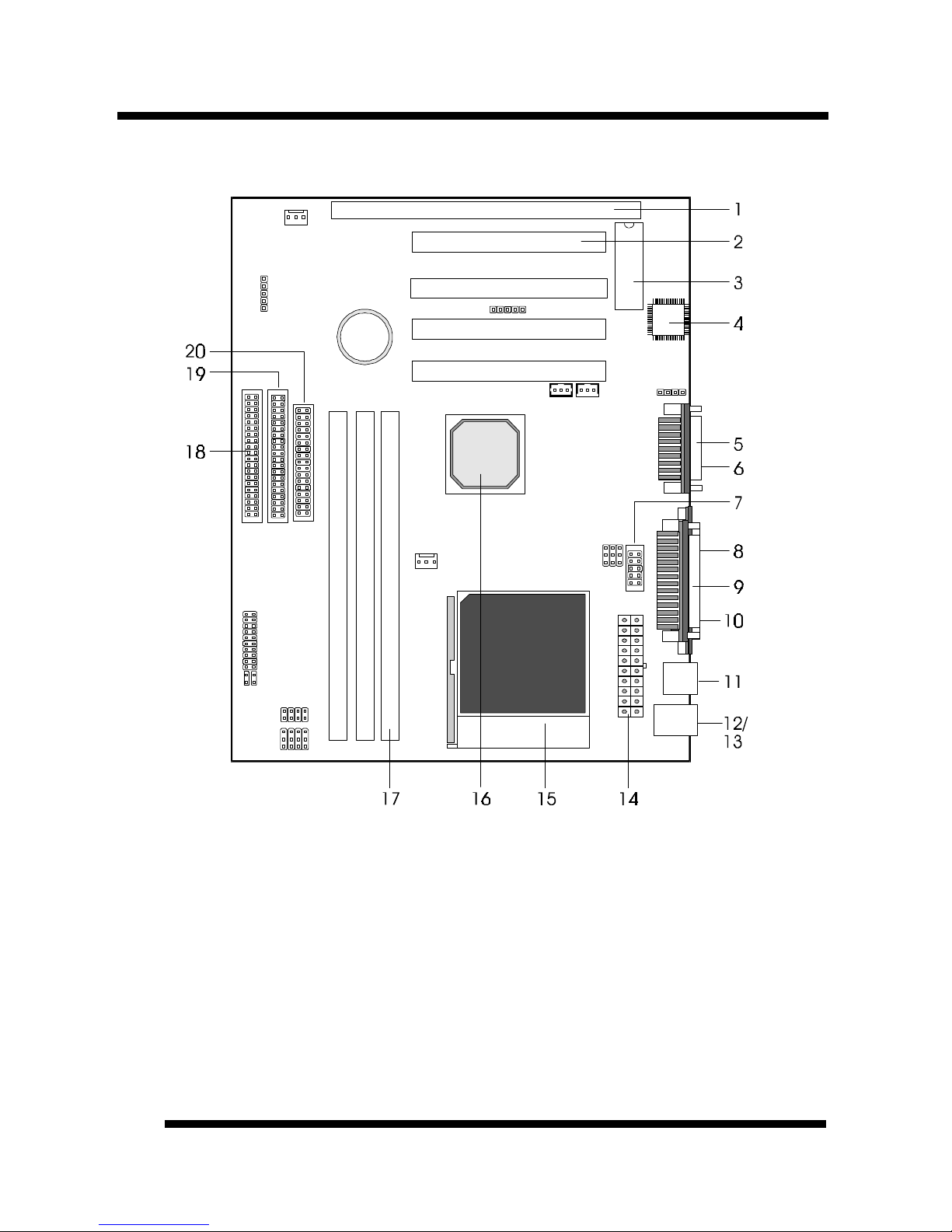
Board Level Feature
1. ISA slot 11. USB connectors
2. PCI slots 12. PS/2 mouse connector (top)
3. Mainboard BIOS 13. PS/2 keyboard connector (bottom)
4.
AC97 codec chip
14. Power connector
5.
MIDI/Game port
15. CPU socket (Socket 7)
6.
Audio port
16. VIA
Apollo MVP4 AGPset
7. COM2 connector 17. DIMM sockets
8. VGA connector 18. Primary IDE connector
9. Printer port connector 19. Secondary IDE connector
10. COM1 connector 20. Floppy connector
* Board Size: Micro-ATX 245 mm x 200 mm (9.6” x 7.7”)
Page 7

INTRODUCTION
Installation Guide
7
1. ISA Slot: (1) 16-bit ISA slot.
2. PCI Slots: (4) 32-bit PCI slots are provided.
3. Mainboard BIOS: Award BIOS supporting “Plug and Play”, DMI, Green
PC specification, on screen setup for Enhanced IDE and Multi-I/O. The BIOS
is FLASH Upgradeable via the AWDFLASH Utility.
4. AC97 Codec Chip: AC97 audio codec chip.
5. MIDI/Game Port: 15-pin female MIDI/Joystick connector.
6. Audio Port: Three 1/8” female jacks for Line Out, Line In and MIC.
7. COM2 Connector: Connects to High-speed UART compatible serial port
bracket. COM2 can be directed to the Infrared Module for wireless connection
capability.
8. VGA Connector: 9-pin VGA connector.
9. Printer Port Connector: EPP and ECP compatible 25-pin D-Sub parallel
port.
10. COM1 Connector: High-speed UART compatible serial port.
11. USB Connectors: These connectors permit the connection of two USB
peripheral devices directly to the port without an external hub. USB is a new
technology supporting printers, fax modems and other telephony device.
12. PS/2 Mouse Connector: Supports PS/2 style mice.
13. PS/2 Keyboard Connector: Supports PS/2 style keyboards.
14. Power Connector: 20-Pin ATX Power Connector.
15. CPU Socket: ZIF Socket 7 for AMD K6-2 / K6-3 up to 450 MHz, Cyrix
up to MII-500, Intel Pentium MMX up to 233 MHz.
16. VIA® Apollo MVP4 AGPset: Supports Socket 7 CPUs, UDMA66 and AGP
2x.
17. DIMM Sockets: (3) 168-pin DIMM sockets are provided to support a
maximum RAM memory capacity of 768 MB. DIMM types of 3.3 Volt true
SDRAM is supported and automatically detected by the BIOS.
18. Primary IDE Connector: Connector for first IDE channel. The on-board
PCI Bus Mastering IDE controller features support for DMA Mode 2 and PIO
Modes 3 and 4 for faster data transfer rates. (2) Connectors are provided for
support of up to (4) IDE devices on two channels. ATAPI Tape Drives and
CD-ROMs are also supported.
19. Secondary IDE Connector: Connector for second IDE channel.
20. Floppy Connector: Built-in floppy controller supports (2) 5.25" or 3.5"
(1.44MB or 2.88MB) floppy drives.
Page 8
INTRODUCTION
Installation Guide
8
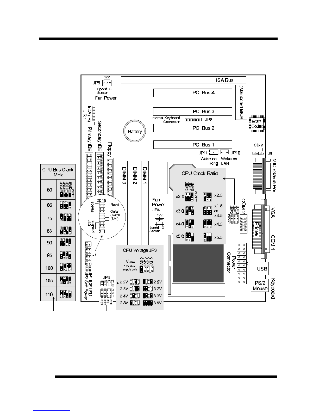
Comprehensive Mainboard View
Page 9
Installation Guide
9
INSTALLATION
Static Precautions
Static electricity can be a serious danger to the electronic components on this mainboard. To
avoid damage caused by electrostatic discharge, observe the following precautions:
ü Don’t remove the mainboard from its anti-static packaging until you are ready to install
it into a computer case. Also, handle add-in cards and modules by the edges or mounting
bracket.
ü Before you handle the mainboard in any way, touch a grounded, anti-static surface, such
as an unpainted portion of the system chassis, for a few seconds to discharge any builtup static electricity.
Installing the CPU
ü WARNING: Use of a CPU Cooling Fan is required to prevent CPU from
overheating. The Fan should be installed first before inserting the CPU into its
socket.
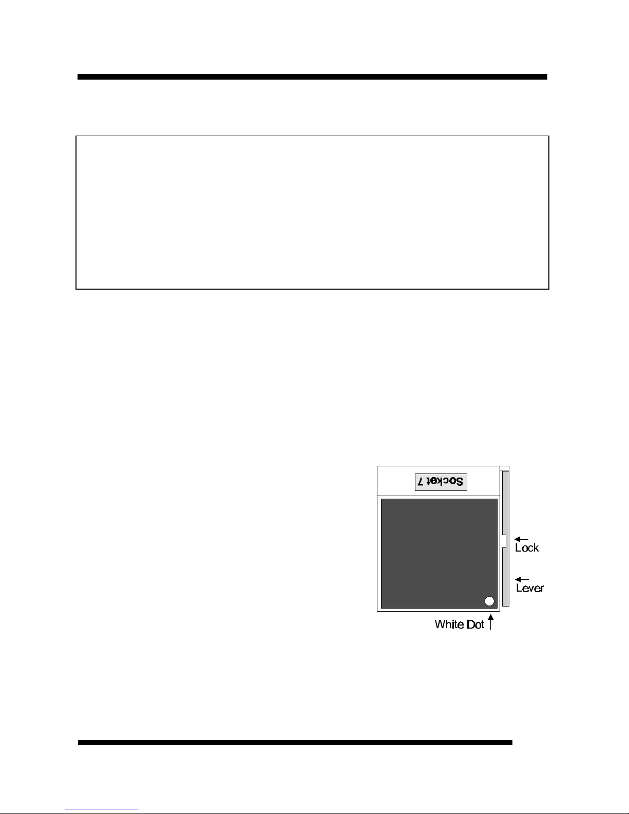
1. Locate the ZIF (Zero Insertion Force) Socket 7.
2. First open the socket by pulling the lever sideways, then upwards. Notice how
the lever locks in place when pressed all the way down.
3. The CPU must be inserted with the correct
orientation. One corner of the CPU has a
“Notch” and looks different that the other
three. This corner is also missing a pin unlike the
other three and is marked with a white dot on
top of the CPU. Align this corner towards the
end of the lever as shown in the figure here.
Insert the CPU, press it down, and close the
lever until it locks into place.
Page 10
INSTALLATION
Installation Guide
10
Setting the Jumpers
Jumpers are used on this mainboard to select various settings and features. A 2-pin
jumper has two settings: Open and Short (or Closed). The jumper is closed by
placing the Jumper Cap across the two pins, thereby connecting them. 3-pin
jumpers can be set to pins 1-2 or 2-3 connected. Pin-1 is labeled on the circuit
board.
3-pin Jumper 2-pin Jumper
Pin 1-2
Open
Pin 2-3
Short
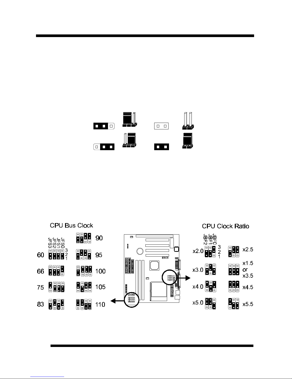
CPU Clock Selection Jumper (JBF0-2 and JFS0-3)
After installing the CPU, you must set the clock selection jumpers to match the
frequency of the CPU. Find the Jumper Blocks labeled JBF0-2 and JFS0-3. Set the
jumpers according to your particular CPU type (a list of current available CPU
settings is provided on the following page).
Page 11

INSTALLATION
Installation Guide
11
Jumper setting for CPU:
CPU Model CPU Clock Bus Clock (JFS0-3) Ratio (JBF0-2)
AMD-K6-III-450MHz 450MHz 100MHz
×
4.5
AMD-K6-III-400MHz 400MHz 100MHz
×
4.0
AMD-K6-2-450MHz 450MHz 100MHz
×
4.5
AMD-K6-2-400MHz 400MHz 100MHz
×
4.0
AMD-K6-2-350MHz 350MHz 100MHz
×
3.5
AMD-K6-2-300MHz 300MHz 100MHz
×
3.0
AMD-K6-2-266MHz 250MHz 100MHz
×
2.5
AMD-K6-2-380MHz 380MHz 95MHz
×
4.0
AMD-K6-2-333MHz 333MHz 95MHz
×
3.5
AMD-K6-300MHz 300MHz 66MHz
×
4.5
AMD-K6-266MHz 266MHz 66MHz
×
4.0
AMD-K6-233MHz 233MHz 66MHz x3.5
AMD-K6-200MHz 200MHz 66MHz x3.0
AMD-K6-166MHz 166MHz 66MHz x2.5
AMD-K5-PR200 66MHz x3.0
AMD-K5-PR166 66MHz x2.5
AMD-K5-PR133 66MHz
×
1.5
Intel Pentium MMX-233 233MHz 66MHz x3.5
Intel Pentium MMX-200 200MHz 66MHz x3.0
Intel Pentium MMX-166 166MHz 66MHz x2.5
Intel Pentium MMX-150 150MHz 60MHz x2.5
Intel Pentium -200 200MHz 66MHz
×
3.0
Intel Pentium -166 166MHz 66MHz
×
2.5
Intel Pentium -150 150MHz 60MHz
×
2.5
Intel Pentium -133 133MHz 66MHz
×
2.0
Intel Pentium -120 120MHz 60MHz
×
2.5
IDT WinChip 2-300 100MHz
×
2.5
IDT WinChip 2-266 100MHz
×
5.0
IDT WinChip 2-233 233MHz 66MHz
×
3.5
IDT WinChip 2-200 200MHz 60MHz
×
3.0
IDT C6-240 240MHz 60MHz
×
4.0
IDT C6-225 225MHz 75MHz
×
3.0
IDT C6-200 200MHz 66MHz
×
3.0
IDT C6-180 180MHz 60MHz
×
3.0
IDT C6-150 150MHz 75MHz x2.0
Page 12

INSTALLATION
Installation Guide
12
RISE MP6 (PR266) 200MHz 100MHz
×
2.0
RISE MP6 (PR233) 190MHz 95MHz
×
2.0
RISE MP6 (PR166) 166MHz 83MHz
×
2.0
•
The Internal (Core) frequency corresponds to the number marked on the CPU. The
External Frequency when multiplied with the Ratio gives the CPU's internal frequency.
•
This table lists the current CPU available. New settings may be available for new CPU
products. Refer to your CPU specifications for more information.
Setting the CPU Voltage Selection Jumper (JP3)
Locate Jumper JP3 on the mainboard. Set this jumper in accordance with your
specific CPU type.
* The Intel MMX CPU is an example of a dual supply chip (2.8V & 3.3V). When single
supply CPUs are used, this setting is not relevant and should be left on the default
(Refer to the CPU documentation).
Page 13

INSTALLATION
Installation Guide
13
The following diagram illustrates all possible CPU Vcore Voltage Selection jumper
settings:
•
If you are uncertain about the speed or voltage requirements of your particular CPU,
you should obtain Technical Documentation from the manufacturer. Such information
is available via the Intel and AMD WWW sites.
Page 14

INSTALLATION
Installation Guide
14
Connections
Cooling Fan (JP4 and JP5)
These connectors are small 3-pin
Header Connectors that provide
12-Volt power for CPU and
chassis cooling fans. Plug in the
fan cable to the connector. Pin-2
corresponds to the RED power
lead as shown:
Power Supply Connector
This mainboard features an ATX-style Power Supply Connector. This connector is
keyed to prevent connection in the wrong direction. Line up the locking
mechanism on the connector from the Power Supply with the tab on the mainboard
connector. Press down until the two connectors are locked.
Page 15

INSTALLATION
Installation Guide
15
System Function Connector Block (J7)
Pins [7 & 9] SMI suspend switch lead - If your system’s case has a suspend
switch, hook the lead from the switch to pins 7 & 9. A suspend switch is used to
save electricity by putting the system into a suspend mode when the computer is
not being used. For this switch to be functional, “Suspend Mode” must first be
enabled in the Power Management Setup in the BIOS Setup utility.
Pins [17 & 19] Reset switch lead - Connects to the Reset Switch lead from the
system’s case. The reset switch is used to “cold-boot” the system without actually
turning off the power, reducing wear and tear on the power supply.
Pins [2 & 6] Suspend LED lead – Pins 2 & 6 connect to the case-mounted
Suspend LED switch.
Pins [14 & 20] Speaker connector - Connects to the Speaker lead from the
system’s case.
Page 16

INSTALLATION
Installation Guide
16
IDE Activity LED (JP1)
Hook the IDE LED lead to this connector, with the RED lead corresponding to
Pin-1.
Soft Power Switch (JP2)
Connects to the Power Switch featured on ATX case designs. This switch must be
hooked up before the system can be powered on, unlike traditional “Baby-AT”
designs where the power switch is located on the Power Supply itself.
Note: Under the following two conditions, you have to press and hold the switch
for more than 4 seconds to power off your system, regardless of the “Soft-Off by
PWRBTN” setting in the Power Management Setup of the BIOS.
•
Shortly after the system is powered on, when the BIOS message is not yet
appear.
•
When CPU hangs.
Page 17

INSTALLATION
Installation Guide
17
IrDA-Compliant Infrared Module Connector (JIR1)
The IrDA connector bracket hooks directly to this connector on the mainboard.
This connector provides support for the optional wireless transmitting and
receiving infrared module. You must first configure through the BIOS setup where
UART2 is directed, COM2 or IrDA.
Page 18

INSTALLATION
Installation Guide
18
Wake-up On LAN Connector (JP10)
The Wake-up On LAN function will allow the network to wake up a Soft Power
Down (Soft-Off) PC. However, if your system is in the Suspend mode, you can
wake-up the system only through an IRQ or DMA interrupt. To use the Wake-up
On LAN function, you must enable the “Power On By Ring/LAN” field in the
Power Management Setup of the Award BIOS. Connect the cable that comes with
your LAN card to this connector on the system board. Refer to the add-in card’s
manual for details.
Note: Your LAN card must support Magic Packet in order to use the Wake-up On
LAN function.
Wake-on-Ring Function (JP11)
The Wake-on-Ring function allows the modem to remotely power on the system.
Install an external modem (normally to COM2) and enable “Power On by
Ring/LAN” function in the Power Management Setup from the BIOS.
For the function to work for an internal modem card, you must also connect the
Wake-on-Ring cable on the modem card to the Wake-on-Ring function connector
on the mainboard.
Page 19

INSTALLATION
Installation Guide
19
Serial and Parallel Ports
A 25-pin D-Sub header is provided on the back panel for a multi-mode bidirectional parallel port.
One 9-pin D-Sub headers are also provided on the back panel for Serial ports.
For the second serial port, plug the 10-pin cable of the serial port bracket to the
COM2 connector on the mainboard.
VGA Connector
This mainboard has built-in VGA features. A 9-pin connector is provided on the
back panel for connecting to the VGA connector from the monitor.
Page 20

INSTALLATION
Installation Guide
20
USB Connectors
These two connectors permit connection of two USB peripheral devices directly to
the system without an external hub.
PS/2 Keyboard and Mouse Connectors
These two connectors are located on the back panel of the mainboard.
USB
PS/2
Keyboard
PS/2
Mouse
Page 21

INSTALLATION
Installation Guide
21
Internal Keyboard Connector
The front panel keyboard connector bracket hooks directly to this 5-pin connector
on the mainboard. Make sure the red lead is oriented toward pin 1.
Floppy Drives
The on-board floppy controller supports (2) floppy disk drives with the floppy
ribbon cable provided. Make sure the RED stripe on the ribbon cable is oriented
towards Pin-1. Notice the “twist” between the sets of connectors on the floppy
cable. The floppy drive “A” position is at the END of the cable, whereas floppy
drive “B” is hooked to one of the connectors on the other side of the twist. The
cable provides both “Edge” and “Pin” connectors for both the A and B positions to
1
Page 22

INSTALLATION
Installation Guide
22
match the connector on your floppy drives.
Page 23

INSTALLATION
Installation Guide
23
IDE Hard Drives and CD-ROMs
The on-board Enhanced IDE controller can support up to (4) IDE hard drives or
other ATAPI devices, such as CD-ROMs. This controller, as with all Enhanced
IDE controllers, consists of both Primary and Secondary ports. Each port has an
associated connector and cable which can support up to (2) ATAPI devices each.
All IDE devices have jumpers which allow the user to configure the device as
either “Master” or “Slave”. A Master device is one that is ALONE on the IDE
cable, whereas a Slave device is installed as a SECOND device on the same cable.
Keep in mind that the Master device will appear before the Slave device in the
CMOS Setup, as well as the Operating System software. *Refer to the device
documentation for jumper settings.
The Secondary IDE port can be used for up to (2) additional ATAPI devices.
Normally it’s recommended that you connect your first hard drive to the Primary
port, and the first CD-ROM to the Secondary.
Make sure to align the RED stripe on the ribbon cable with Pin-1 on the mainboard
IDE connector. On most hard drives and CD-ROMs, the RED stripe should be
oriented towards the power connector of the device.
1 1
Page 24

INSTALLATION
Installation Guide
24
MIDI/Game Port
You may plug a joystick or game pad to this 15-pin female connector for game
playing, or connect a MIDI device for playing or editing audio.
Audio Port
You can connect powered speakers or headphones to Line Out jack. Cassette
players or other external audio sources can be connected to Line In jack. Plug in
your microphones to MIC jack.
Note:
To use the on-chip direct sound AC97 audio support, make sure that the “OnChip
Sound” option in Chipset Features Setup of the BIOS is enabled (default).
To use the on-chip legacy SoundBlaster-compatible audio support, make sure that
the “Onboard Legacy Audio” options in Integrated Peripherals Setup of the
BIOS is set according to your system configuration before driver installation.
Page 25

INSTALLATION
Installation Guide
25
Audio Connectors (J9)
A CD Audio connector is available for connecting the CD-ROM drive using CD
audio cables. Make sure red lead is oriented toward pin 1.
1
CD-IN
Page 26

INSTALLATION
Installation Guide
26
notch notch
DIMM3
DIMM2
1
1
1
DIMM1
1
Installing the Memory Modules (DIMM)
•
This mainboard has three sockets available for 168-pin DIMMs. They can be
3.3 volt Unbuffered Synchronous DRAMs (SDRAM), 3.3 volt FPG or EDO
DRAMs.
•
To ensure reliability, it is recommended to use PC100 SDRAM for
your 100MHz clocked SDRAM performance requirement.
•
Via Apollo MVP4 chipset does not support Register DIMMs.
•
DIMM Sizes supported: 8MB, 16MB, 32MB, 64MB, 128MB and 256MB
•
A total of (3) DIMMs can be installed for a maximum RAM capacity of
768MB.
To insert the DIMMs, the modules must be oriented in the correct way. Notice the
notches of the DIMM. Align these notches as shown in the diagram below. Gently
push the DIMM until the retainers on both sides of the socket lock the module in
place. To remove a DIMM, push the retainers outwards to release the module then
pull the module out of the socket.
Page 27

INSTALLATION
Installation Guide
27
Installing the Support Drivers and Utilities
Included in your mainboard package you can find a CD-ROM containing support
drivers and utilities. Just insert the CD-ROM, and from the Autorun screen, click
the driver/utility that you want to install. Follow the on-screen instructions to
complete the installation.
* The screen may look different under different color mode.
More utilities can be found under the “Utilities” folder of the CD-ROM.
Page 28

INSTALLATION
Installation Guide
28
Special Note on the Onboard Audio Features
Using the Onboard Audio Features
To use the on-chip direct sound AC97 audio support, make sure that the “OnChip
Sound” option in Chipset Features Setup of the BIOS is enabled (default).
To use the on-chip legacy SoundBlaster-compatible audio support, make sure that
the “Onboard Legacy Audio” options in Integrated Peripherals Setup of the
BIOS is set according to your system configuration before driver installation.
For Windows NT 4.0
Ensure Windows NT4.0 is up and running properly. Install the audio drivers
before Service Pack 4. If Service Pack 4 is installed before the audio drivers, you
may not see peripheral devices including the CD-ROM drive due to Service Pack 4
problem.
Page 29

INSTALLATION
Installation Guide
29
Special Note on VIA MVP4 and VGA Drivers
Before installing the AGP VGA drivers under Windows 95/98, specific software
support must be included in your system first:
Windows 95
A. Though Windows 95 OSR2.0 supports AGP, it is necessary that you first upgrade
OSR2.0 to OSR2.1 with a USB upgrade to take full advantage of the AGP features.
B. To access the advanced 3D features in Windows 95, you also need to first install the
Microsoft DirectX 5.0.
C. Then install the following VIA drivers found in the supplied CD-ROM:
1) VIA PCI Bridge driver.
2) VIA Bus Master driver.
3) VIA VxD driver.
Make sure all the above are included in your system before you install the display driver.
Windows 98
Install VIA VxD driver found in the supplied CD-ROM before you install the display driver.
Page 30

Installation Guide
30
SOFTWARE SUPPORT
For detailed information, please refer to the BIOS, Driver & Utility Guide
included in your mainboard package.
Mainboard BIOS
Shortly after the system is powered on, provided that the system is properly setup,
you will see the message:
Press DEL to enter SETUP
•
Press the DEL key to enter the Award BIOS Setup program.
The Main Menu will appear on the screen. Use the arrow keys to select among the
items and press <Enter> to accept and enter the sub-menu.
ROM PCI/ISA BIOS (xxxxxxxx)
CMOS SETUP UTILITY
AWARD SOFTWARE, INC.
STANDARD CMOS SETUP INTEGRATED PERIPHERALS
BIOS FEATURES SETUP SUPERVISOR PASSWORD
CHIPSET FEATURES SETUP USER PASSWORD
POWER MANAGEMENT SETUP IDE HDD AUTO DETECTION
PNP / PCI CONFIGURATION SAVE & EXIT SETUP
LOAD BIOS DEFAULTS EXIT WITHOUT SAVING
LOAD SETUP DEFAULTS
Esc : Quit
↑ ↓ → ←
: Select Item
F10 : Save & Exit Setup (Shift) F2 : Change Color
Select LOAD SETUP DEFAULTS for optimum system performance.
Page 31

SOFTWARE SUPPORT
Installation Guide
31
Flash BIOS Programming Utility
Since this mainboard features FLASH BIOS, the user can simply re-program the
old BIOS using the AWDFLASH Utility (found under “Utilities” folder of the
supplied CD-ROM) as follows:
1. First, boot the system with DOS or to “Safe Mode” under Windows 95. This is
the only correct way to run the AWDFLASH Utility program.
2. Make sure the files “AWDFLASH.EXE” and the updated “BIN” file (which
contains the actual BIOS code) are in the same directory.
3. Changing to the directory where the two required files exist, type: AWDFLASH
and press [ENTER]. The AWDFLASH Utility Screen appears:
4. Type in the name of the new BIOS (.bin) file and hit [ENTER].
5. Backup the old BIOS by entering the name of the new backup file (such as
“backup.bin”) and press [ENTER].
6. To begin programming, hit “y”. The Utility can be aborted at this time by
hitting “n”.
7. A bar indicator will show the progress of the programming operation. After
successful completion, hit the reset button or power off the computer.
Be sure to perform “LOAD SETUP DEFAULTS” for your new BIOS to
synchronize the previous BIOS with the updated BIOS.
Page 32

SOFTWARE SUPPORT
Installation Guide
32
Symbios SCSI Configuration Utility
This mainboard features built-in Symbios SCSI BIOS. The Symbios SCSI
Configuration Utility is a menu driven utility that allows you to view and change
the default configuration settings for host adapters using Symbios 53C8XX chips.
In most cases you should not need to change the default configuration of your host
adapter. You may decide to alter these default values if there is a conflict between
device settings, or if you need to optimize system performance. A message appears
on your computer monitor (for about 5 seconds) during boot that looks like this:
Press Crtl-C to start Symbios Configuration Utility
If you decide to press Ctrl-C during boot, the following message appears:
Please wait, invoking Symbios Configuration Utility …
After a brief pause, your computer will display the Main Menu of the utility.
Note: Pressing Ctrl-A after memory count during re-boot allows you to recover the
default settings and reconfigure.
DMI Utility
This mainboard supports the Desktop Management Interface (DMI), which is a
new method of providing enterprise management for personal computers. The
main component of DMI is the Management Information Format Database (MIF),
which contains information about the computer system and its components, such as
BIOS version/vendor, CPU speed/type, memory size/type, L1/L2 cache, port
connectors (IDE, floppy, 2S/1P, USB, keyboard, mouse, ), slots … etc. Using DMI,
remote PC management software is able to obtain various information about the
system, including hardware profiles, capabilities, operational status, installation
dates, and other information about the system and its components.
This DMI utility, DMICFG.EXE (found under “Utilities” folder of the supplied
CD-ROM), allows you to add additional information, such as serial numbers,
vendor information, and enclosure/chassis configurations, into the MIF.
Page 33

FCC & DoC Compliance Statement
This device complies with Part 15 of the FCC rules, operation is subject to the following
two conditions.
1. This device may not cause harmful interference and,
2. This device must accept any interference received, including interference that may cause
undesired operation.
This equipment has been tested and found to comply with limits for a Class B digital
device, pursuant to Part 15 of the FCC rules. These limits are designed to provide
reasonable protection against harmful interference in residential installations. This
equipment generates, uses, and can radiate radio frequency energy, and if not installed and
used in accordance with the instructions, may cause harmful interface to radio
communications. However, there is no guarantee that interference will not occur in a
particular installation. If this equipment does cause interference to radio or television
equipment reception, which can be determined by turning the equipment off and on, the
user is encouraged to try to correct the interference by one or more of the following
measures:
l
Reorient or relocate the receiving antenna.
l
Move the equipment away from the receiver.
l
Plug the equipment into an outlet on a circuit different from that to which the receiver is
connected.
l
Consult the dealer or an experienced radio/television technician for additional
suggestions.
The FCC requires the user to be notified that any change or modifications to the equipment
by the user not expressly approved by the grantee or manufacturer could void the user’s
authority to operate such equipment. The use of shielded cables for connection of the
monitor to the graphics card is required to assure compliance with FCC regulations.
Page 34

SOFTWARE SUPPORT
Installation Guide
34
27-0M0586-42
 Loading...