

Page 1
Quick Reference Guide (rev 5.00) DC-390U2B/W SCSI Adapter
Tekram Technology Co., Ltd
1
INTRODUCTION
The DC-390U2B/W is an Ultra2 SCSI (Small Computer System Interface) bus to PCI bus
host adapter, which complies to the PCI 2.1 specification with Plug-&-Play (PnP) readiness.
Installing this adapter in your PCI system allows connection of up to 15 SCSI devices.
Your DC-390U2B/W is a 16-bit, Low Voltage Differential (LVD) / Single Ended (SE)
SCSI solution for your computer. It can support both legacy Fast SCSI and Ultra SCSI
devices, as well as the newest LVD Ultra2 SCSI devices.
The DC-390U2B/W supports ASPI (Advanced SCSI Programming Interface) managers for
most of the operating systems available today to assure operation with popular third party
applications.
Device drivers are also supported for the major operating systems for compatibility with a
full range of SCSI peripherals including CD-ROMs, Photo CDs, tape backups, scanners,
removable media and SCSI hard drives.
HARDWARE INSTALLATION
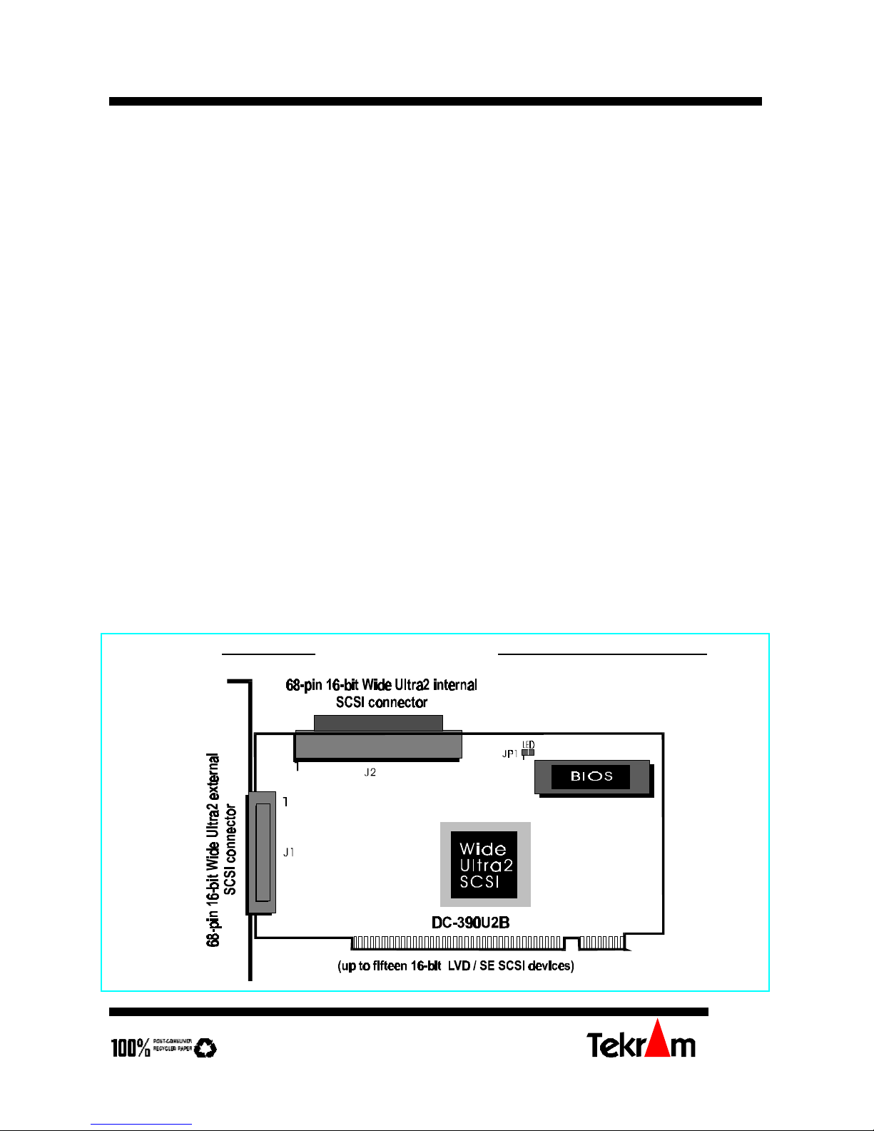
Board Layout
DC-390U2B Wide Ultra2 SCSI adapter
Page 2
DC-390U2B/W SCSI Adapter Quick Reference Guide (rev 5.00)
Tekram Technology Co., Ltd
2
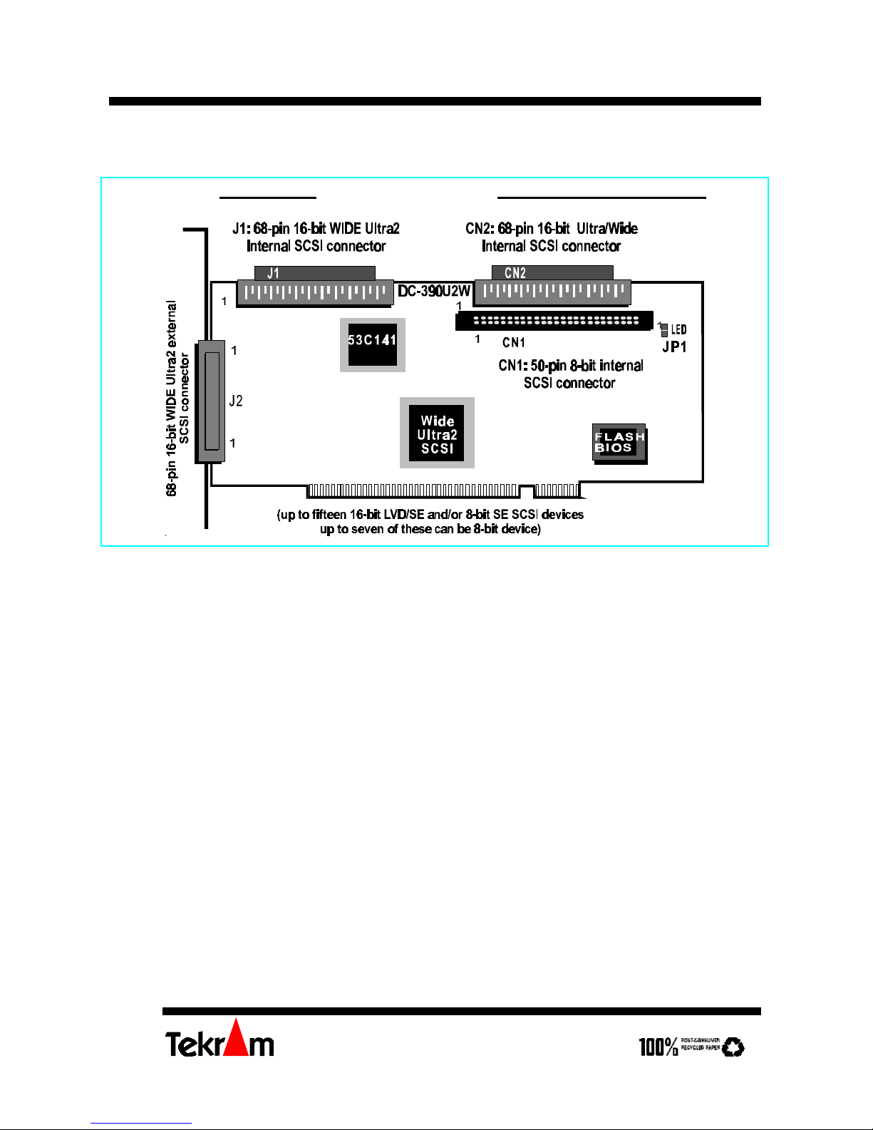
DC-390U2W Wide Ultra2 SCSI adapter
Installing the Adapter
Important: Handle circuit boards by the edges or bracket. Touch the bare metal of your
computer case before handling any circuit boards to prevent static discharge damage.
1. Power OFF and unplug your system.
2. Remove the computer cover. Refer to your system user’s manual for instructions.
3. Align the gold-fingered edge on your card with an empty PCI expansion slot and gently
insert it into place. You may need to remove the cover from the rear of the PCI
expansion slot that you selected.
4. Replace the screws to secure the card retaining bracket in place.
Setting the SCSI IDs
Each SCSI device attached to the SCSI card, as well as the card itself, must be assigned a
unique SCSI ID number. SCSI ID 7 is preset to the SCSI card, giving it the highest priority
on the SCSI bus.
The SCSI IDs of your peripheral devices are usually set with jumpers or with a switch on
the peripheral. Refer to the peripheral‘s manual to determine the ID and how to change it.
Page 3

Quick Reference Guide (rev 5.00) DC-390U2B/W SCSI Adapter
Tekram Technology Co., Ltd
3
Any SCSI device with SCAM (SCSI Configured AutoMatically) can assign its own SCSI ID
dynamically and resolves SCSI ID conflicts automatically. You do not need to manually
assign SCSI IDs to theses peripherals. See User’s Manual for details of how to enable
SCAM support.
SCSI Device Activity LED Indicator (JP1)
JP1 is used to indicate activity of the SCSI devices controlled by the DC-390U2B/W, and
should be connected to the cable leading to the Hard Drive LED on the front panel of your
computer case.
Connecting the SCSI Peripherals
Model # External Internal
DC-390U2B
J1: 68-pin; 16-bit (wide Ultra2) J2: 68-pin; 16-bit (wide Ultra2)
DC-390U2W
J2: 68-pin; 16-bit (wide Ultra2) CN1: 50-pin; 8-bit
CN2: 68-pin; 16-bit (wide)
J1: 68-pin; 16-bit (wide Ultra2)
External SCSI connector: This high density D-type SCSI connector is for connecting
external SCSI devices.
Internal SCSI connector: The internal flat cable should connect to the internal SCSI
connector with its colored stripe, normally red, aligned with Pin 1 of the connector.
Maximum length of the SCSI bus is determined by the number of devices and the data
transfer rate. The maximum allowable cable lengths for the DC-390U2B/W is 12.5 meters
(41 feet).
If there are internal devices connected, the internal cable length must be included in the
measurement of SCSI bus length
Note:
For DC-390U2B, mixing Fast/Ultra devices with Ultra2 devices brings the entire SCSI bus
to Ultra SCSI speed and cable requirements.
For DC-390U2W, it is recommended that you keep your Ultra2 devices on connectors J1
and J2, non Ultra2 devices on CN1 and CN2. Mixing Ultra2 devices with non Ultra2
devices will bring the Ultra2 devices to Ultra SCSI performance level.
Page 4

DC-390U2B/W SCSI Adapter Quick Reference Guide (rev 5.00)
Tekram Technology Co., Ltd
4
Checking the Terminators on the SCSI Bus
In order to stabilize the SCSI bus, only two sets of terminators can be installed - one at each
end of the SCSI bus. The DC-390U2B/W itself is equipped with Active Terminators that
automatically switch from Enabled to Disabled or vice versa by scanning the devices
connected on the SCSI bus. So, manual termination adjustments are not required.
If you are not sure about how to set the terminators for other SCSI devices, please refer to
the User’s Manual for details.
Note1: Since the termination of internal Ultra2 devices are set to disabled at the factory
and cannot be changed, special Ultra2 internal SCSI ribbon cables with a
terminator installed at the end are specified for the operation with Ultra2 SCSI
devices.
Note2: There are two types of termination available on SCSI devices, active and passive.
Active termination is strongly recommended to ensure system integrity,
particularly when devices with high transfer rates are being used. A SCSI CDROM drive usually comes with a passive terminator. For proper termination, it is
recommended that you keep this terminator disabled, i.e. avoid connect the CD-
ROM drive at the end of the SCSI bus
DRIVER INSTALLATION
Easy DOS ASPI Driver Installation
1. Insert Disk 1.
2. Under DOS, type A:\DOSINST then press <Enter>. This will update the
CONFIG.SYS and AUTOEXEC. BAT files automatically.
Further information about drivers and step-by-step installation procedures can be found in
the User’s Manual.
Other Driver Installation
For Driver installation of other O.S. (especially for Windows 95, NT, and SCO OpenServer
5.0.4), please refer to the User’s Manual.
* For the driver and BIOS updates, please visit our website at
http://www.tekram.com, or ftp.tekram.com for Linux and FreeBSD support.
 Loading...