

Page 1
DC-390 Series SCSI Adapter Quick Reference Guide (rev 4.02)
Tekram Technology Co., Ltd
1
INTRODUCTION
The DC-390 series is a SCSI (Small Computer System Interface) bus to PCI bus host
adapter, which complies to the PCI 2.1 specification with Plug-&-Play (PnP) readiness. The
maximum SCSI devices supported are: DC-390/390U (7) and DC-390F (15). By using the
Disconnect/Reconnect technique, performance degradation during multitasking operations is
prevented. Other enhanced SCSI-2 features such as scatter-gather and command-tag queuing
are supported.
The DC-390 series supports ASPI (Advanced SCSI Programming Interface) managers for
most of the operating systems available today to assure operation with popular third party
applications.
Device drivers are also supported for the major operating systems for compatibility with a
full range of SCSI peripherals including CD-ROMs, Photo CDs, tape backups, scanners,
removable media and SCSI hard drives.
HARDWARE INSTALLATION
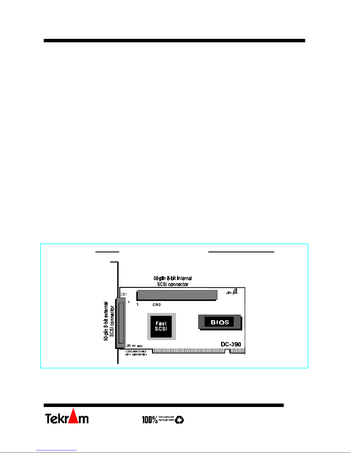
Board Layout
DC-390 Fast SCSI-2 adapter
Page 2
DC-390 Series SCSI Adapter Quick Reference Guide (rev 4.02)
Tekram Technology Co., Ltd
2
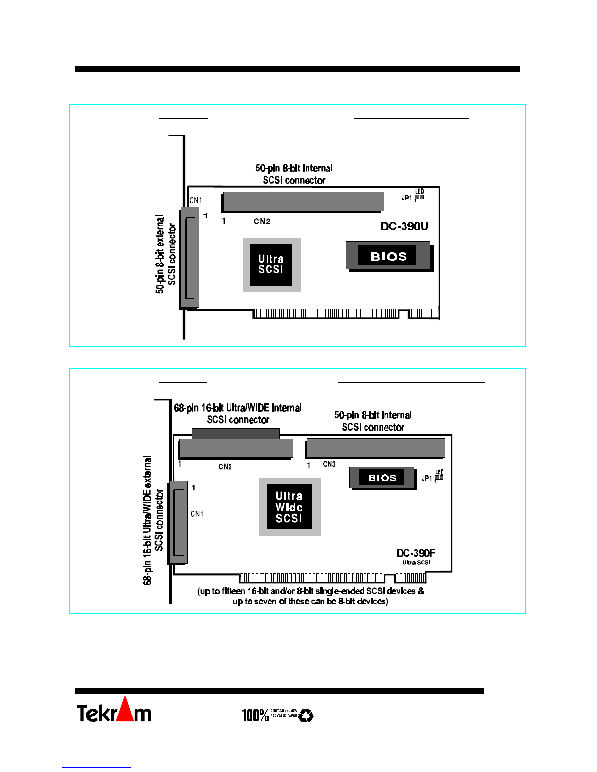
DC-390U Ultra SCSI-3 adapter
DC-390F Ultra Wide SCSI-3 adapter
Page 3
DC-390 Series SCSI Adapter Quick Reference Guide (rev 4.02)
Tekram Technology Co., Ltd
3
Installing the Adapter
Important: Handle circuit boards by the edges or bracket. Touch the bare metal of your
computer case before handling any circuit boards to prevent static discharge damage.
1. Power OFF and unplug your system.
2. Remove the computer cover. Refer to your system user’s manual for instructions.
3. Align the gold-fingered edge on your card with an empty PCI expansion slot and gently
insert it into place. You may need to remove the cover from the rear of the PCI
expansion slot that you selected.
4. Replace the screws to secure the card retaining bracket in place.
5. Continue to the following sections for jumper settings and SCSI peripheral
connections.
Jumper Settings
DC-390: JP1 (LED); JP2 (ROM)
DC-390U/F: JP1 (LED)
SCSI Device Activity LED Indicator (JP1)
JP1 is used to indicate activity of the SCSI devices controlled by the DC-390 series, and
should be connected to the cable leading to the Hard Drive LED on the front panel of your
computer case.
ROM BIOS jumper (JP2/DC-390)
You can install a maximum of 4 DC-390s in the same system. Normally, each card will
consume a 16KB memory block for its BIOS. The function of JP2 is to save memory space
by allowing the BIOS of the first adapter to control the additional adapters. When two or
more DC-390s are installed in the same system, set JP2 to Enabled for the first adapter, and
Disabled for all additional DC-390s.
(Refer to the BIOS ROM Mapped AT option in the Adapter Information setup screen for
host adapter BIOS address settings.)
Connecting the SCSI Peripherals
Model # CN1 (External) CN2 (Internal) CN3 (Internal)
DC-390 50-pin; 8-bit 50-pin; 8-bit
DC-390U 50-pin; 8-bit 50-pin; 8-bit
DC-390F*
68-pin; 16-bit (wide) 68-pin; 16-bit (wide) 50-pin; 8-bit
*: Only two of the three connectors can be used to connect SCSI devices at the same
time.
Page 4

DC-390 Series SCSI Adapter Quick Reference Guide (rev 4.02)
Tekram Technology Co., Ltd
4
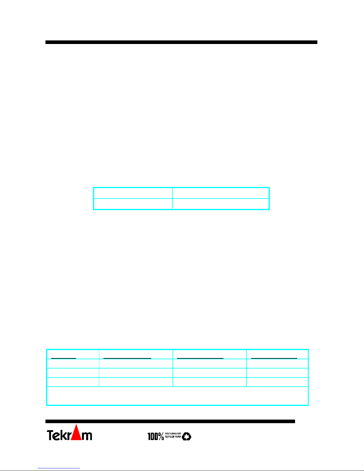
The following table summarizes the maximum allowable cable lengths for the DC-390
series:
Model # SCSI Type Data Xfer Rate Max. # of
Devices
Max. Cable Length
DC-390 SCSI-2 10 MB/Sec 8 3 meters (9.8 feet)
DC-390U/F Ultra SCSI 20/40 MB/Sec 4 3meters (9.8 feet)
DC-390U/F Ultra SCSI 20/40 MB/Sec 8 1.5 meters (4.9 feet)
* If there are internal devices connected, the internal cable length must be included in
the measurement of SCSI bus length.
• If the mainboard of your system supports Symbios SCSI, it is recommended that you
disable it. Consult your mainboard’s user’s manual for details.
Checking the Terminators on the SCSI Bus
In order to stabilize the SCSI bus, only two sets of terminators can be installed - one at each
end of the SCSI bus. The DC-390 series itself is equipped with Active Terminators that
automatically switch from Enabled to Disabled or vice versa by scanning the devices
connected on the SCSI bus. So, manual termination adjustments are not required.
If you are not sure about how to set the terminators, please refer to the User’s Manual for
details.
DRIVER INSTALLATION
Easy DOS ASPI Driver Installation
1. Insert Disk 1.
2. Under DOS, type A:\DOSINST then press <Enter>. This will update the
CONFIG.SYS and AUTOEXEC. BAT files automatically.
Further information about drivers and step-by-step installation procedures can be found in
the User’s Manual.
Other Driver Installation
For Driver installation of other O.S. (especially for Windows 95, NT, and SCO OpenServer
5.0.4), please refer to the User’s Manual.
* For the driver and BIOS updates, please visit our website at
http://www.tekram.com, or ftp.tekram.com for Linux and FreeBSD support.
 Loading...