

Page 1

DC-310 series SCSI Adapter Quick Reference Guide (rev 2.2)
Tekram Technology Co., Ltd
1
Introduction
The DC-310 series has two adapters: DC-310U, an Ultra-SCSI adapter based on the
Symbios Logic SYM53C860 SCSI Chip, and DC-310, a Fast SCSI-2 adapter based on
SYM53C810 SCSI Chip. Designed to provide a low cost, easy to implement SCSI solution,
this adapter utilises the built-in Symbios Logic SCSI BIOS (SDMS BIOS version 4.x) on
supported mainboards, such as Tekram P5 VX/TX and P6/Pentium_II series.
Fully Plug & Play and PCI 2.1 compliant, enhanced SCSI features include
Disconnect/Reconnect, Scatter/Gather, and Tag Queuing to greatly improve overall system
performance, particularly under multitasking environments.
Jumper-less hardware design, Active SCSI Bus Termination, and 32-bit PCI DMA Bus
Mastering are a few more of the advanced features built-in to the DC-310 series adapters,
providing the best performance and ease of use possible.
Checklist
l This manual l 50-pin internal SCSI cable
l Symbios SDMS 4.1 driver diskettes (3)
Disk # Installation
Disk1:
1. DOS
2. OS2
1. \DOS\DOS.TXT (for both DOS & Win 3.1)
2. \OS2\OS2.TXT
Disk2:
1. Win95
2. NT 3.5x/4.x
1. \WIN95\WIN95.TXT
2. \WINNT\8XXNT.TXT
Disk3:
1. NetWare
2. DOS Utilities
1. \NETWARE\DDFS\NET_DDFS.TXT
2. ASPIFMT.EXE
CONFIG.EXE
l Drivers for SCO Unix 5.0 and UnixWare 2.x are available via our website at
http://www.tekram.com
Specification
SCSI Performance
SCSI Chip:
• Symbios SYM53C860 (DC-310U) or SYM53C810 (DC-310)
SCSI devices:
• Max: 7
SCSI bus transfers:
• DC-310U => Async: 7MB/sec & Sync: 20MB/sec
• DC-310 => Async: 5MB/sec & Sync: 10MB/sec
Bus master data
transfers:
• 132MB/sec (at 33MHz)
• 80-byte DMA FIFO for 2/4/8/16 dwords burst across PCI bus
Page 2
DC-310 series SCSI Adapter Quick Reference Guide (rev 2.2)
Tekram Technology Co., Ltd
2
PCI Integration
• Full 32-bit PCI DMA bus master
• Jumper-less design
• Active SCSI bus termination (* DC-310: optional)
∗ Termination is required for both ends of a SCSI bus.
∗ DC-310U: Need to do nothing for the termination on the DC-310U,
since it’s equipped a pair of Active Terminators on U1B & U2B.
∗ DC-310: (Same to DC-310U if a pair of active terminators are
installed on the U1B & U2B). If it’s Passive Terminators, which
are resistor arrays, used on RP1/RP2/RP3, you’ll need to remove
them if the DC-310 is not located at one end of the SCSI bus.
White dot on the resistor array must point to the small box while
installed.
Reliability
SYMTolerANT technology with:
• Active negation of SCSI Data, Parity, Request, and Acknowledge
signals for improved fast SCSI transfer rates.
• Input signal filtering on SCSI receivers improves data integrity,
even in noisy cabling environments.
Drivers & Utilities
• DOS, Win3.1, Win95, NT 3.5/4.x, NetWare 3.12/4.x, SCO
3.2v4.2/5.0, UnixWare 2.x., OS/2 Warp
• BIOS (& Flash utility), Installation, Low Level Format.
Mainboard BIOS
Support
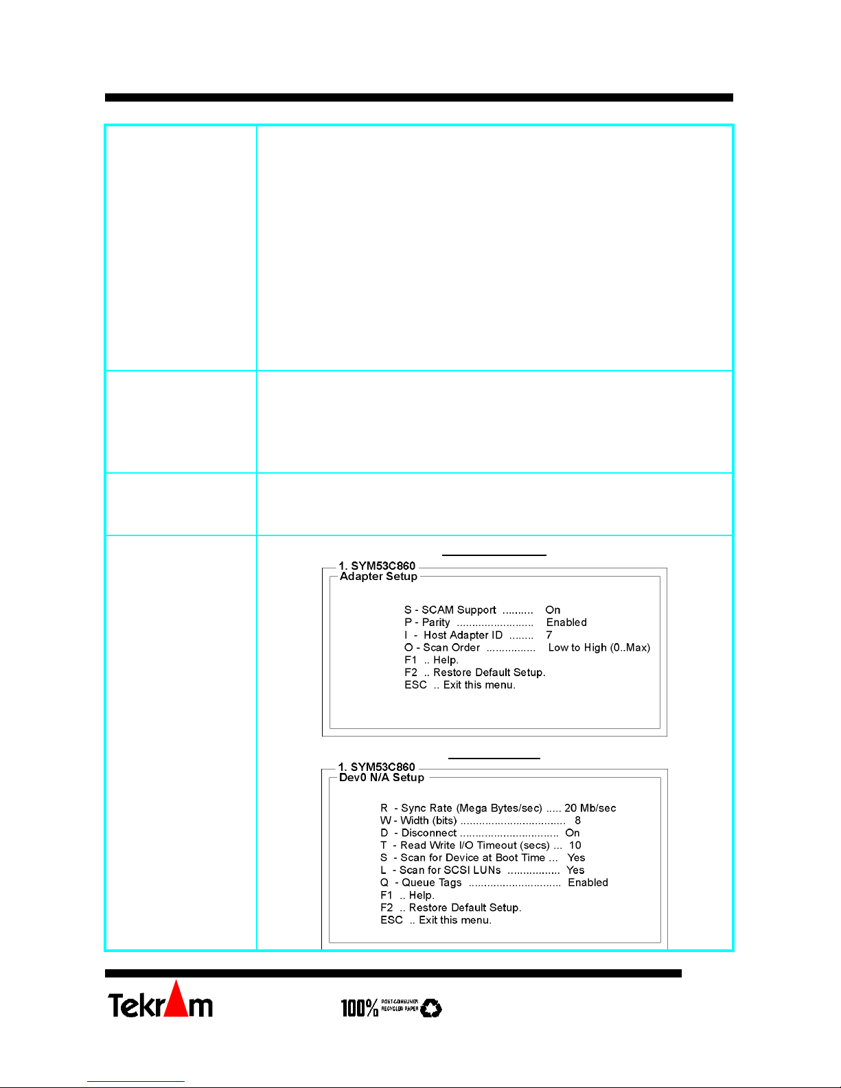
Adapter Setup
Device Setup
Page 3

DC-310 series SCSI Adapter Quick Reference Guide (rev 2.2)
Tekram Technology Co., Ltd
3
Adapter Utilities Menu
When you select a host adapter from the main menu, the following screen is displayed:
• Adapter Setup: views and changes the selected adapter settings.
SCAM Support - SCAM (SCSI Configured AutoMatically) is the SCSI Plug and Play
protocol supported by this Symbios BIOS version 4.X.
Parity - The Symbios host adapters always generate parity, but some SCSI devices do not.
So you are offered the option of disabling parity checking.
Note: When disabling parity checking, it is also necessary to disable disconnects for all
devices, as parity checking for the reselection phase is not disabled. If a device does
not generate parity, and it disconnects, the I/O never completes because the reselection
never completes.
Host SCSI ID - It’s not suggested to change your host adapter SCSI ID (default: 7), as this
gives it the highest priority on the SCSI bus. However, if you have two adapters on the
same SCSI bus, you should give one of them a currently unassigned ID to avoid
duplication of SCSI IDs.
Scan Order - This option allows you to tell the host adapter BIOS and your device drivers
to scan the SCSI bus from low to high (o to max) SCSI ID, or from high to low (max to
0) SCSI ID. If you have more than one device on the SCSI bus, changing the scan order
changes the order in which drive letters are assigned by the system.
• Device Selections: views and changes settings for the devices attached to the selected
adapter.
The above menu provides information about individual SCSI devices attached to the
selected host adapter, and the adapter itself. To make changes to these settings select a
device from this display and press <Enter> to bring up the individual Device Setup menu.
Device Setup Menu
When you select a specific device from the Device Selection menu, your computer displays
the following Device Setup menu. The settings in this menu effect individual SCSI devices
attached to the selected host adapter. Changes made from this menu do cause the system to
reboot upon exit from the SCSI Configuration utility.
Sync Rate (Mega Bytes/sec) - Defines the maximum transfer rate the host adapter attempts
to negotiate. The host adapter and a SCSI device must agree to a rate they can both handle.
Width (bits) - Sets the maximum data width the host adapter attempts to negotiate. The
host adapter and a SCSI device must agree to a width they can both handle. Only host
adapters that can do 16 bit data transfers have this option enabled.
Disconnect - SCSI devices have the ability to disconnect from the bus during an I/O
transfer. This option tells the host adapter whether or not to allow a device to disconnect.
Some devices run faster with disconnects enabled (mostly newer devices), while some run
faster with disconnects disabled (mostly older devices).
Page 4

DC-310 series SCSI Adapter Quick Reference Guide (rev 2.2)
Tekram Technology Co., Ltd
4
Read Write I/O Timeout (secs) - This option sets the time the host adapter waits for a
read, write, verify, or seek command to complete before trying the I/O transfer again. Since
this provides a safeguard allowing the system to recover if an I/O operation fails, it is
recommended that you always set the time-out to a value greater than zero (no time-out).
Scan for Device at Boot Time - When there is a device you do not wish to make available
to the system, set this option to No for that device. Also, on a bus with only a few devices
attached, you can speed up boot time by changing this setting to No for unused SCSI IDs.
Scan for SCSI LUNs - You can set this option to No if you have problems with a device
that responds to all LUNs whether they are occupied or not.
Queue Tags - If your device driver can issue queue tags, this option allows you to enable or
disable the issuing of queue tags during I/O requests.
FCC NOTICE
This equipment has been tested and found to comply with limits for a Class B digital device, pursuant to Part
15 of the FCC rules. These limits are designed to provide reasonable protection against harmful interference
in residential installations. This equipment generates, uses, and can radiate radio frequency energy, and if not
installed and used in accordance with the instructions, may cause harmful interface to radio communications.
However, there is no guarantee that interference will not occur in a particular installation. If this equipment
does cause interference to radio or television equipment reception, which can be determined by turning the
equipment off and on, the user is encouraged to try to correct the interference by one or more of the following
measures:
• Reorient or relocate the receiving antenna
• Move the equipment away from the receiver
• Plug the equipment into an outlet on a circuit different from that to which the receiver is connected
Consult the dealer or an experienced radio/television technician for additional suggestions.
Only equipment certified to comply with Class B should be attached to this equipment, and
must have shielded interface cables.
The FCC requires the user to be notified that any change or modifications to the equipment
by the user not expressly approved by the grantee or manufacturer could void the user’s
authority to operate such equipment.
Each DC-310U/DC-310 is equipped with an FCC compliance label which shows only the
FCC Identification number: FCC ID: KHADC310.
This device complies with Part 15 of the FCC rule. Operation is subjected to the following
two conditions:
1. this device may not cause harmful interference and
2. this device must accept any interference received, including interference that may cause
undesired operation.
(All other products names are trademarks or copyrights of their respective owners.)
 Loading...