

Page 1

User’s Manual
REV: 1.00
Date: May - 98
MAINBOARD
* All other product names are trademarks or copyrights of their respective owners.
Page 2

FCC & DOC Compliance Statement
This device complies with Part 15 of the FCC rules, operation is subject to the following
two conditions.
1. This device may not cause harmful interference and,
2. This device must accept any interference received, including interference that may cause
undesired operation.
This equipment has been tested and found to comply with limits for a Class B digital
device, pursuant to Part 15 of the FCC rules. These limits are designed to provide
reasonable protection against harmful interference in residential installations. This
equipment generates, uses, and can radiate radio frequency energy, and if not installed and
used in accordance with the instructions, may cause harmful interface to radio
communications. However, there is no guarantee that interference will not occur in a
particular installation. If this equipment does cause interference to radio or television
equipment reception, which can be determined by turning the equipment off and on, the
user is encouraged to try to correct the interference by one or more of the following
measures:
l Reorient or relocate the receiving antenna.
l Move the equipment away from the receiver.
l Plug the equipment into an outlet on a circuit different from that to which the receiver is
connected.
l Consult the dealer or an experienced radio/television technician for additional
suggestions.
The FCC requires the user to be notified that any change or modifications to the equipment
by the user not expressly approved by the grantee or manufacturer could void the user’s
authority to operate such equipment. The use of shielded cables for connection of the
monitor to the graphics card is required to assure compliance with FCC regulations.
.
22
User’s ManualUser’s Manual
Page 3

Table of Contents
INTRODUCTION........................................................................................5
Product Description........................................................................................ 5
Item Checklist ................................................................................................5
Features & Specifications ...............................................................................6
Board Level Feature.......................................................................................7
Comprehensive Mainboard View....................................................................9
INSTALLATION.......................................................................................10
Installing the CPU........................................................................................10
Setting the Jumpers ......................................................................................12
Connections..................................................................................................13
Installing the Memory (DIMM)....................................................................19
Installing an AGP Card................................................................................19
MAINBOARD BIOS SETUP.....................................................................20
About the BIOS............................................................................................20
Main Menu...................................................................................................21
Standard CMOS Setup..................................................................................22
BIOS Features Setup.....................................................................................25
Chipset Features Setup .................................................................................28
Power Management Setup ............................................................................31
PNP/PCI Configuration Setup.......................................................................33
Load BIOS Defaults......................................................................................35
Load Setup Defaults......................................................................................35
Integrated Peripherals Setup.........................................................................36
Supervisor Password and User Password Setting...........................................38
IDE HDD Auto Detection.............................................................................39
Save & Exit Setup / Exit Without Saving......................................................39
User’s ManualUser’s Manual
33
Page 4

TABLE OF CONTENTSTABLE OF CONTENTS
PCI Device Listing .......................................................................................39
FLASH BIOS PROGRAMMING UTILITY.................................................40
DMI UTILITY ............................................................................................ 41
HARDWARE MONITORING UTILITY......................................................42
AudioRack 32 User Guide
44
User’s ManualUser’s Manual
Page 5

INTRODUCTION
þ The mainboard
þ Celeron CPU Retention Kit:
Product Description
This mainboard represents the highest level of technology available in PC Mainboards
today. Through careful designing of this microATX mainboard, System Integrators and End
users can enjoy a lower-cost solution for their PC needs without sacrificing the benefits of
ATX. The microATX form factor addresses the cost requirement by reducing the mainboard
size and therefore cutting down the system size, which lowers overall system cost. A smaller
mainboard is made possible by reducing the number of I/O slots.
This mainboard also features “SLOT 1” architecture, a modular design that supports Intel
Pentium® II as well as Celeron
processor technologies as well as the transition to newer processor technologies.
®
processors. The mocroATX form factor supports the current
Fully “Plug & Play” compatible via an Award BIOS, this mainboard facilitates easy system
configuration and peripheral setup. Advanced BIOS features include Intelligent Hardware
Monitoring and Alert functions. The Award BIOS also supports ACPI readiness and is
compatible with PC97 specification. With support for up to 256MB of System RAM (Type
auto-detected by mainboard BIOS), 3.3V SDRAM, and 3.3V EDO, this mainboard is the
ideal foundation for high-end computer systems.
Item Checklist
Your mainboard package should include the items listed below. Damaged or missing items
should be reported to your vendor.
®
þ Floppy disk ribbon cable
þ IDE ribbon cable
þ (1) Diskette containing software for
þ (3) Diskettes or (1) CD-ROM
updating the FLASH BIOS and IDE
drivers
containing the following software
support–
§ ESS Solo-1 Audio Windows 95
drivers & Wave-table
§ ESS Solo-1 Audio Windows NT
drivers
§ AudioRack32 Audio Application
User’s ManualUser’s Manual
- Racks × 2
þ This User’s Manual
¨ Optional Pentium II CPU Retention
Kit:
- Rack with nuts × 1
- Washer with screws × 2
¨ Optional Thermal Sensor Cable
55
Page 6

INTRODUCTIONINTRODUCTION
Features & Specifications
Processor SLOT 1 support Intel Pentium II (233 ~333 MHz) as well as
Chipset Intel 440EX AGPset
BIOS Award PCI BIOS, support ACPI, DMI, Green PC, Plug-and-Play,
System Memory 2× 168-pin DIMM Sockets support up to 256 MB (SDRAM) /
On-board I/O
Features
Advanced
Features
PCI Bus Master
IDE
Expansion Slots 1× 32-bit AGP slot
ATX Double
Decker
ATX Power
Connector
* For Boards
with On-Board
Audio Features
Form Factor Micro-ATX size 9.6″ by 7″ ( 245mm by 180mm )
®
Celeron
Boot from CD-ROM, SCSI, LS-120, and ZIP devices
512MB (EDO) memory capacity
Support 8/16/32/64/128 MB memory modules
1×Floppy Port (Up to 2.88MB)
1×Parallel Port (EPP, ECP Port)
2×Serial Ports (16550 Fast UART Compatible)
2xUSB Ports
1×IrDA TX/RX Header
1xWake-up On LAN Header
1xPower state Header
1. Accelerated Graphics Port (AGP) slot supported
2. Hardware monitoring (Voltage, CPU Fan, Temperature)
3. Modem Ring-in Power on
2×UltraDMA/33 IDE Ports support
UltraDMA/33: 33MB/Sec.
2× 32-bit PCI Bus Master slots
1× PCI/ ISA shared
2×USB Ports
1×PS/2 Keyboard Port
1×PS/2 Mouse Port
1×Parallel Port
2×COM Ports
3V, 5V and 12V 20-Pin ATX Power connector
processors
ESS PCI Sound Chip on Board– Support Software Wavetable
1×MIDI/game port
1×Audio Jacks: Line Out, Line In, and Mic.
66
User’s ManualUser’s Manual
Page 7
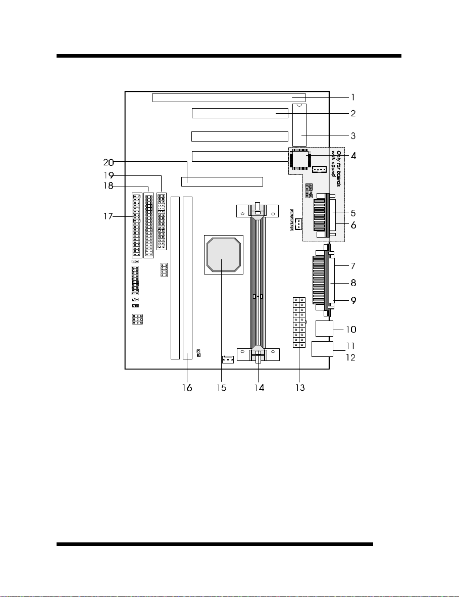
Board Level Feature
INTRODUCTIONINTRODUCTION
1. ISA slot 11. PS/2 mouse connector (top)
2. PCI slots 12. PS/2 keyboard connector (bottom)
3. Mainboard BIOS 13. Power connector
4. Sound Chip 14. SLOT 1 (CPU)
5. MIDI/Game Port (top) 15.
6. Audio Port (bottom) 16. DIMM sockets
7. COM2 connector 17. Primary IDE connector
8. Printer port connector 18. Secondary IDE connector
9. COM1 connector 19. Floppy connector
10. USB connectors 20. AGP slot
* Board Size: MicroATX 245 mm x 180 mm (9.6” x 7”)
Intel 440EX chipset
User’s ManualUser’s Manual
77
Page 8

INTRODUCTIONINTRODUCTION
1. ISA SLOT: (1) 16-bit ISA slot. Due to space limitation, this slot can be used only when
PCI slot 3 is not occupied.
2. PCI SLOTS: (3) 32-bit PCI slots are provided, however, PCI Slot 3 can be used only
when the ISA slot is not occupied.
3. MAINBOARD BIOS: Award BIOS supporting “Plug and Play”, DMI, Green PC
specification, on screen setup for Enhanced IDE and Multi-I/O. The BIOS is FLASH
Upgradeable via the AWDFLASH Utility.
4. * Sound Chip: ESS PCI Sound Chip supporting software wavetable.
5. * MIDI/Game Port: 15-pin female MIDI/Joystick connector.
6. * Audio Port: Three 1/8” female jacks for Line Out, Line In and MIC.
7. COM2 CONNECTOR: High-speed UART compatible serial port. COM2 can be
directed to the Infrared Module for wireless connection capability.
8. PRINTER PORT CONNECTOR: EPP and ECP compatible 25-pin D-Sub parallel
port.
9. COM1 CONNECTOR: High-speed UART compatible serial port.
10. USB CONNECTORS: These connectors permit the connection of two USB peripheral
devices directly to the port without an external hub. USB is a new technology
supporting printers, fax modems and other telephony device.
11. PS/2 MOUSE CONNECTOR: Supports PS/2 style mice.
12. PS/2 KEYBOARD CONNECTOR: Supports PS/2 style keyboards.
13. POWER CONNECTOR: 20-Pin ATX Power Connector.
14. SLOT 1: Slot 1 CPU socket for Pentium® II as well as Celeron
15. INTEL® 440EX CHIPSET: Features SDRAM, Ultra DMA/33 and AGP support.
16. DIMM SOCKETS: (2) 168-pin DIMM sockets are provided to support a maximum
RAM memory capacity of 256 MB. DIMM types of 3.3 Volt true SDRAM is supported
and automatically detected by the BIOS.
17. PRIMARY IDE CONNECTOR: Connector for first IDE channel. The on-board PCI
Bus Mastering IDE controller features support for DMA Mode 2 and PIO Modes 3 and
4 for faster data transfer rates. (2) Connectors are provided for support of up to (4) IDE
devices on two channels. ATAPI Tape Drives and CD-ROMs are also supported.
18. SECONDARY IDE CONNECTOR: Connector for second IDE channel.
19. FLOPPY CONNECTOR: Built-in floppy controller supports (2) 5.25" or 3.5"
(1.44MB or 2.88MB) floppy drives.
20. AGP SLOT: AGP (Accelerated Graphics Port) is a new bus interface for high
performance graphics capabilities, especially 3D.
®
CPUs.
* For the mainboards with on-board audio features.
88
User’s ManualUser’s Manual
Page 9
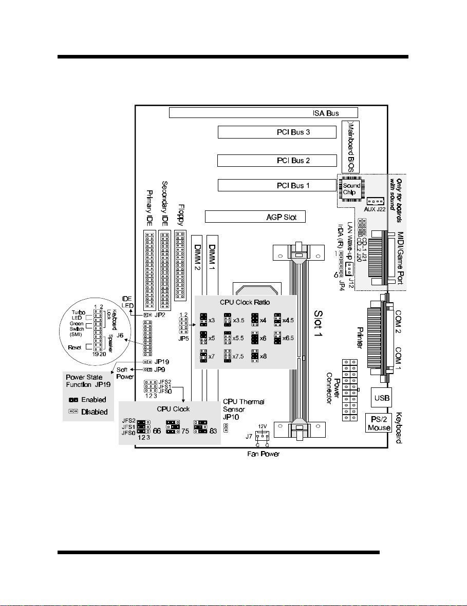
Comprehensive Mainboard View
INTRODUCTIONINTRODUCTION
User’s ManualUser’s Manual
99
Page 10
INSTALLATION
Static Precautions
Static electricity can be a serious danger to the electronic components on this mainboard. To
avoid damage caused by electrostatic discharge, observe the following precautions:
ü Don’t remove the mainboard from its anti-static packaging until you are ready to install
it into a computer case. Also, handle add-in cards and modules by the edges or mounting
bracket.
ü Before you handle the mainboard in any way, touch a grounded, anti-static surface, such
as an unpainted portion of the system chassis, for a few seconds to discharge any builtup static electricity.
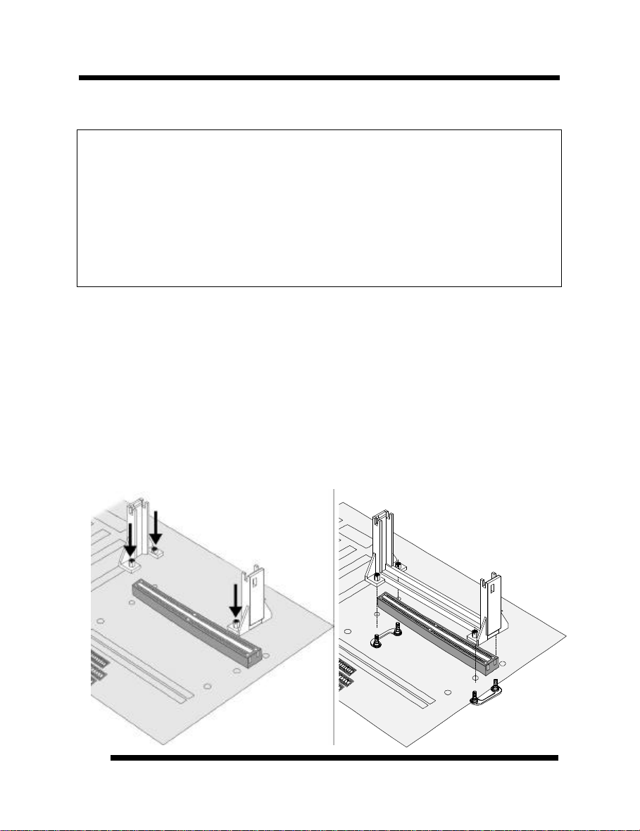
Installing the CPU
Your mainboard features “SLOT 1” architecture, a modular design that can accommodate
Intel® Pentium® II as well as Celeron
retention mechanism first.
®
processors. Before installing the CPU, attach the
Attaching the Retention Mechanism
For Celeron CPUs: Locate SLOT 1. Push the Retention Mechanisms until they are firmly
locked into place. (Fig.1)
For Pentium II CPUs: Locate SLOT 1. Attach the Retention Mechanism as illustrated
below. (Fig.2)
* Make sure all components
are correctly oriented.
Fig. 1 Fig. 2
1010
User’s ManualUser’s Manual
Page 11
INSTALLATIONINSTALLATION
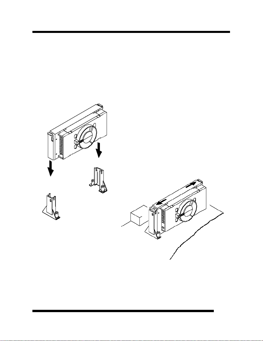
Installing Pentium® II or Celeron® CPU
üü Warning: It is required to use a CPU Cooling Fan to prevent the CPU from
overheating. Install the fan first before inserting the CPU into the socket.
1. Slide the CPU down into the retention mechanism. Make sure the CPU is correctly
oriented. (Fig. 1)
2. Seat the CPU firmly into the slot until the two tabs on the CPU click outwards to lock
the CPU in place. (Fig. 2)
Fig. 1
User’s ManualUser’s Manual
Fig. 2
1111
Page 12
INSTALLATIONINSTALLATION
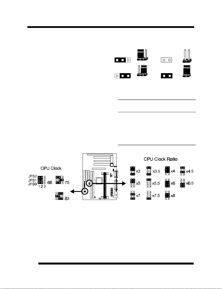
Setting the Jumpers
Jumpers are used on this mainboard to
select various settings and features. A 2-pin
jumper has two settings: Open and Short (or
Closed). The jumper is closed by placing
the Jumper Cap across the two pins, thereby
connecting them. 3-pin jumpers can be set
to pins 1-2 or 2-3 connected. Pin-1 is
labeled on the circuit board.
3-pin Jumper 2-pin Jumper
Pin 1-2 Open
Pin 2-3 Short
Setting the CPU Clock Selection Jumpers (JP5, JFS0, JFS1 and JFS2)
After installing the CPU, you must set the
clock selection jumper to match the frequency
of the CPU. Find the Jumper Blocks labeled
JFS0, JFS1, JFS2 and JP5 on the mainboard.
Set the jumper according to the table at right
for the CPU frequency you are using.
The CPU Clock corresponds to the number
marked on the CPU. The Bus Clock when
multiplied with the Ratio gives the CPU Clock.
CPU
Clock
233MHz x3.5 66MHz
266MHz x4.0 66MHz
300MHz x4.5 66MHz
333MHz x5.0 66MHz
366MHz x5.5 66MHz
400MHz x6.0 66MHz
Ratio Bus Clock
These jumpers automatically set the ISA Clock as well.
• Intel 440EX chipset supports only 66 MHz bus clock. The 75/83MHz settings are for
internal test only. Over-clocking may cause serious system damage.
• If you are uncertain about the speed requirements of your particular CPU, you should
obtain Technical Documentation from the manufacturer. Such information is available
via the Intel WWW site.
1212
User’s ManualUser’s Manual
Page 13
INSTALLATIONINSTALLATION
GND
12V
GND
Connections
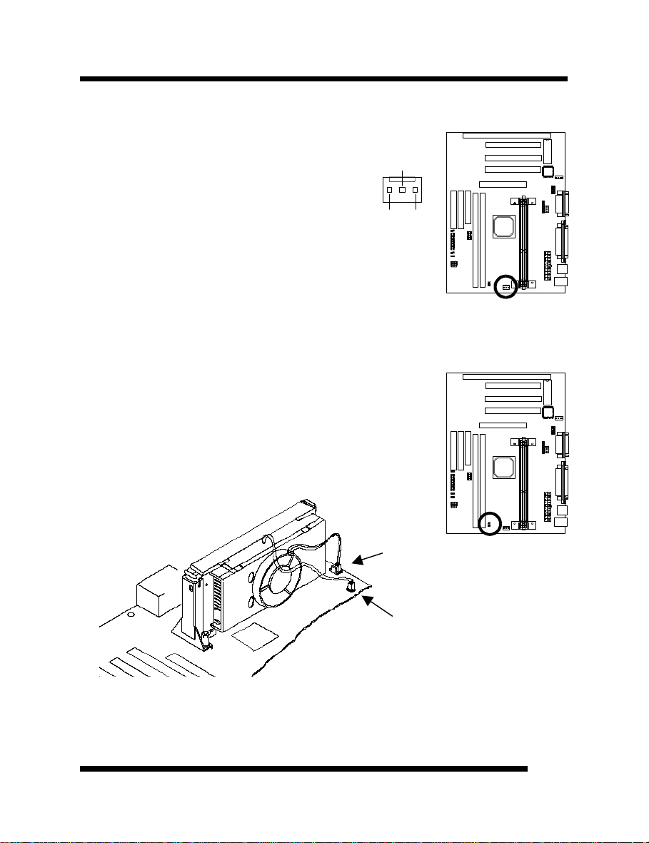
Cooling Fan (J7)
J7 is a small 3-pin Header Connector that provides
12-Volt power for CPU Cooling Fan. Plug in the fan
cable to the connector. Pin-2 corresponds to the
RED power lead as shown:
CPU Thermal Sensor (JP10)
For the CPU Temperature Monitoring function to work properly,
you must use the optional CPU Cooling Fan provided by the
manufacturer. Hook the Thermal Sensor lead attached on the Fan
to this connector, regardless of the polarity.
Fan Power
Thermal
Sensor
User’s ManualUser’s Manual
1313
Page 14
INSTALLATIONINSTALLATION
Soft Power Switch (JP9)
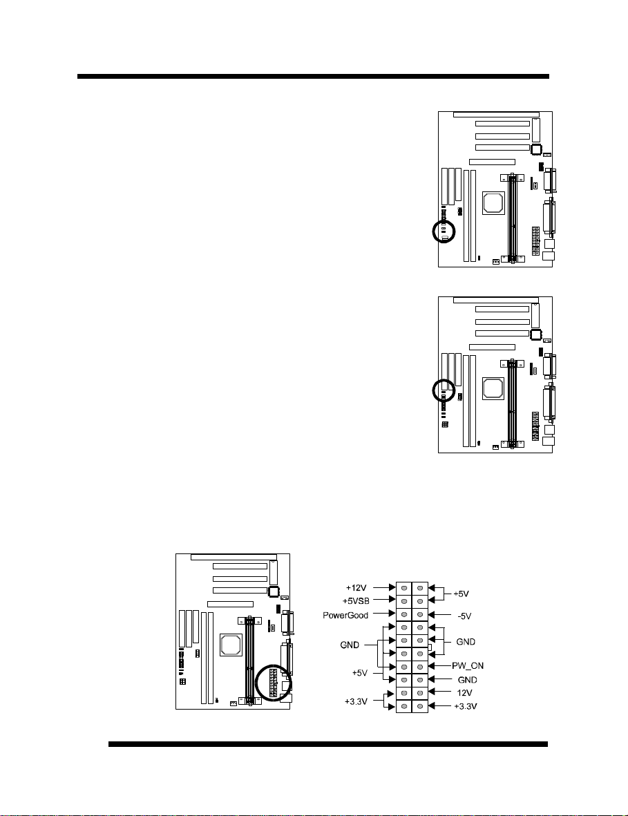
Connects to the Power Switch featured on ATX case designs. This
switch must be hooked up before the system can be powered on,
unlike traditional “Baby-AT” designs where the power switch is
located on the Power Supply itself.
Note: Under the following two conditions, you have to press and
hold the switch for longer than 4 seconds to power off your
system, regardless of the BIOS setting. (Refer to page 31.)
• Shortly after the system is powered on, when the BIOS
message is not yet appear.
• When CPU hangs.
IDE Activity LED (JP2)
Hook the IDE LED lead to this connector, with the RED
lead corresponding to Pin-1.
Power Supply Connector
This mainboard features an ATX-style Power Supply Connector. This connector is keyed to
prevent connection in the wrong direction. Line up the locking mechanism on the connector
from the Power Supply with the tab on the mainboard connector. Press down until the two
connectors are locked.
1414
User’s ManualUser’s Manual
Page 15
INSTALLATIONINSTALLATION
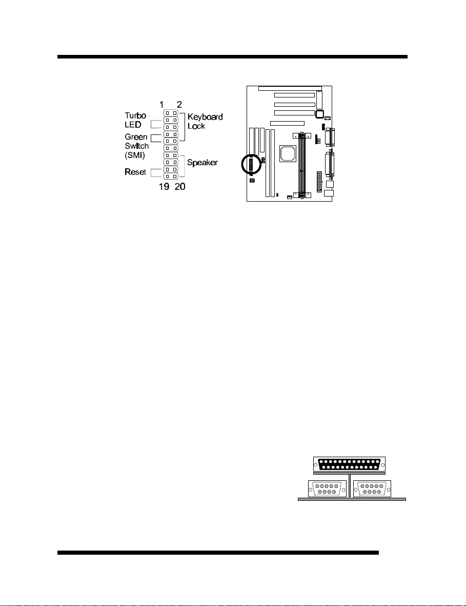
System Function Connector Block (J6)
Pins [3 & 5] Turbo LED switch - The Turbo function is not supported by this
mainboard. Therefore, the Turbo LED will always remain lit as long as the system power
is on.
Pins [7 & 9] SMI suspend switch lead - If your system’s case has a suspend switch,
hook the lead from the switch to pins 7 & 9. A suspend switch is used to save electricity
by putting the system into a suspend mode when the computer is not being used. This
switch could also be used by the Turbo switch on the front of the system, since this
mainboard does not support that function. For this switch to be functional, it must first be
enabled in the Power Management Setup in the BIOS Setup utility.
Pins [17 & 19] Reset switch lead - Connects to the Reset Switch lead from the system’s
case. The reset switch is used to “cold-boot” the system without actually turning off the
power, reducing wear and tear on the power supply.
Pins [2, 6, 8, 10] Keyboard lock switch lead - Pins 2 & 6 connect to the Power LED
from the system’s case. Pins 8 & 10 connect to the case-mounted keylock switch.
Pins [14 & 20] Speaker connector - Connects to the Speaker lead from the system’s
case.
Serial and Parallel Ports
A 25-pin D-Sub header is provided on the back panel for a
multi-mode bi-directional parallel port.
Two 9-pin D-Sub headers are also provided on the back
panel for Serial ports.
* Modem Ring-In Power On
Install a modem (normally to COM2) and enable Resume by
User’s ManualUser’s Manual
ParallelPort
COM1
C OM2
1515
Page 16
INSTALLATIONINSTALLATION
Ring/LAN function from BIOS setup. (Please refer to page 31). This allows the modem to
remotely power on the system or return it to full power out of suspend/standby mode.
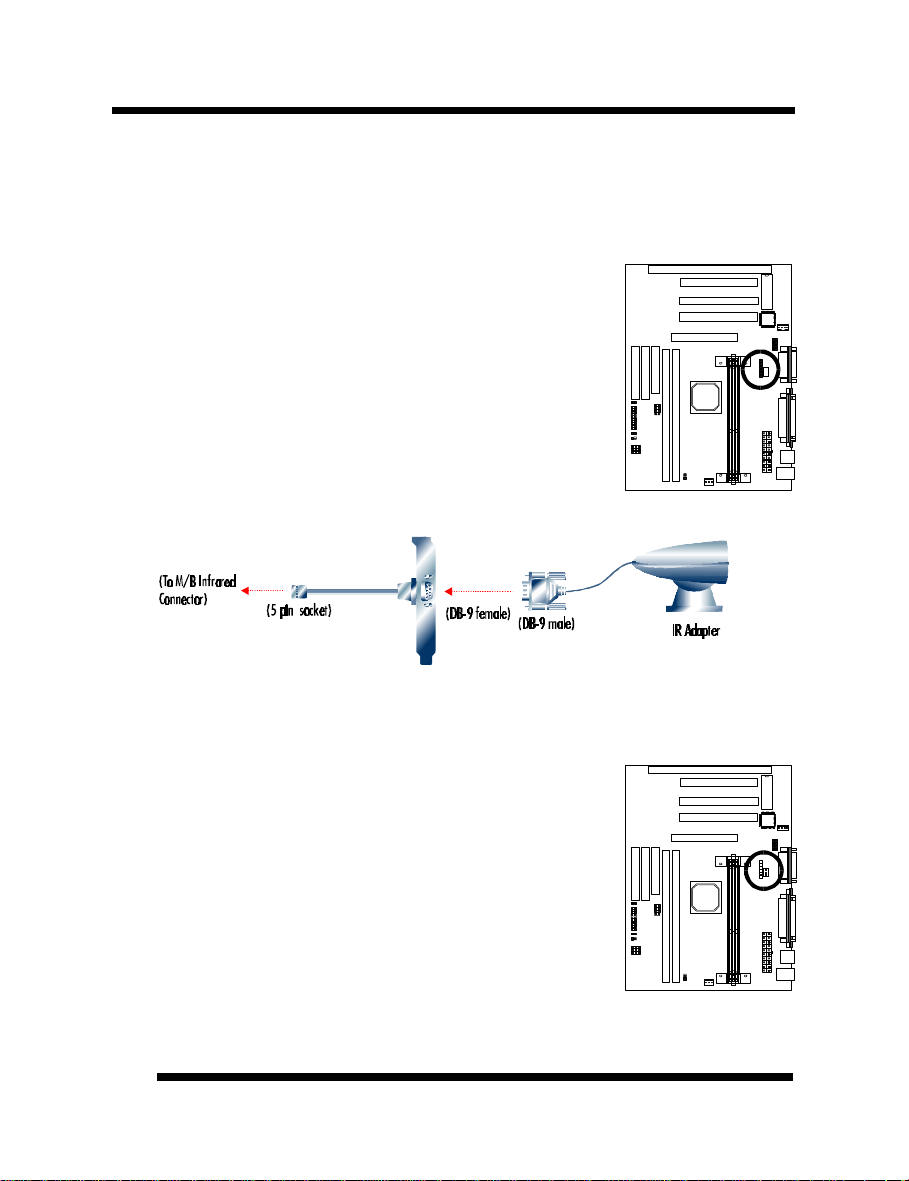
IrDA-Compliant Infrared Module Connector (JP4)
The IrDA connector bracket hooks directly to this connector on the
mainboard. This connector provides support for the optional
wireless transmitting and receiving infrared module. You must
first configure through the BIOS setup where UART2 is directed,
COM2 or IrDA.
* Pin 6 is reserved for consumer IR.
Wake-up On LAN Connector (J12)
The Wake-up On LAN function will allow the network to wake up
a Soft Power Down (Soft-Off) PC. However, if your system is in
the Suspend mode, you can wake-up the system only through an
IRQ or DMA interrupt. To use the Wake-up On LAN function, you
must enable the “Resume By Ring/LAN” field in the Power
Management Setup of the Award BIOS. Connect the cable that
comes with your LAN card to location J12 on the system board.
Refer to the add-in card’s manual for details. Note: Your LAN card
must support Magic Packet in order to use the Wake-up On LAN
function.
1616
User’s ManualUser’s Manual
Page 17
INSTALLATIONINSTALLATION
B
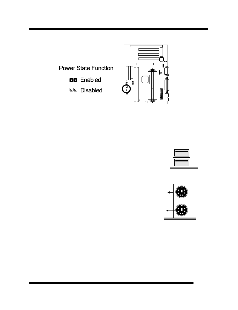
Power State Function (JP19)
This feature will power-on the PC when power returns after a power failure. Set JP19 to On
(short) to enable this function.
“PWRON After PWR-Fail” in the Power Management Setup must be set accordingly.
Refer to pages 31 and 32 for more information.
USB Connector
This 8-pin connector permits connection of two USB peripheral
devices directly to the system without an external hub.
US
PS/2 Keyboard and Mouse Connectors
These two connectors are located on the back panel of the
mainboard.
Floppy drives
PS/2
Mouse
PS/2
Keyboard
The on-board floppy controller supports (2) floppy disk drives with the floppy ribbon cable
provided. Make sure the RED stripe on the ribbon cable is oriented towards Pin-1. Notice
the “twist” between the sets of connectors on the floppy cable. The floppy drive “A”
position is at the END of the cable, whereas floppy drive “B” is hooked to one of the
connectors on the other side of the twist. The cable provides both “Edge” and “Pin”
connectors for both the A and B positions to match the connector on your floppy drives.
User’s ManualUser’s Manual
1717
Page 18
INSTALLATIONINSTALLATION
IDE Hard Drives and CD-ROMs
The on-board Enhanced IDE controller can support up to (4) IDE hard drives or other
ATAPI devices, such as CD-ROMs. This controller, as with all Enhanced IDE controllers,
consists of both Primary and Secondary ports. Each port has an associated connector and
cable which can support up to (2) ATAPI devices each.
All IDE devices have jumpers which allow the user to configure the device as either
“Master” or “Slave”. A Master device is one that is ALONE on the IDE cable, whereas a
Slave device is installed as a SECOND device on the same cable. Keep in mind that the
Master device will appear before the Slave device in the CMOS Setup, as well as the
Operating System software. *Refer to the device documentation for jumper settings.
The Secondary IDE port can be used for up to (2) additional ATAPI devices. Normally it’s
recommended that you connect your first hard drive to the Primary port, and the first CDROM to the Secondary.
Make sure to align the RED stripe on the ribbon cable with Pin-1 on the mainboard IDE
connector. On most hard drives and CD-ROMs, the RED stripe should be oriented towards
the power connector of the device.
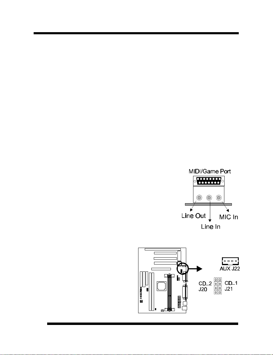
MIDI/Game Port
You may plug a joystick or game pad to this 15-pin female
connector for game playing, or connect a MIDI device for
playing or editing audio.
Audio Port
You can connect powered speakers or headphones to Line Out
jack. Cassette players or other external audio sources can be
connected to Line In jack. Plug in your microphones to MIC
jack.
Audio Connectors (J20, J21 & J22)
The AUX connector J22 is used to connect
an internal audio source, such as a TV
Tuner or an MPEG card. Two CD Audio
connectors are available (J20 and J21) for
connecting CD-ROM drives using CD
audio cables.
1818
User’s ManualUser’s Manual
Page 19
INSTALLATIONINSTALLATION
Installing the Memory (DIMM)
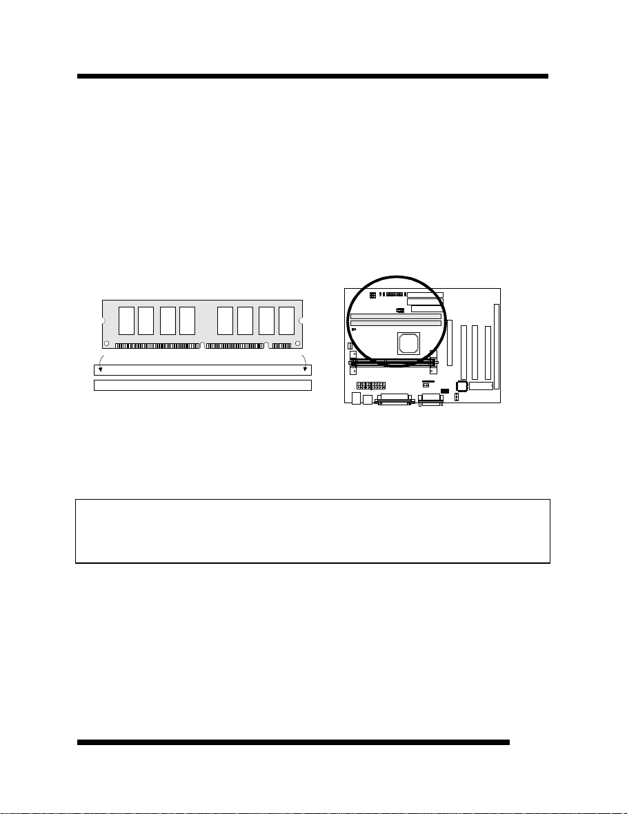
• Your mainboard has two sockets available for 168-pin DIMMs. They must be 3.3 volt
Unbuffered Synchronous DRAMs (SDRAM) or 3.3 volt EDO RAM.
• DIMM Sizes supported: 8MB, 16MB, 32MB, 64MB, and 128MB
• A total of (2) DIMMs can be installed for a maximum RAM capacity of 256MB.
To insert the DIMMs, the modules must be oriented in the correct way. Notice the notches
of the DIMM. Align these notches as shown in the diagram below. Gently push the DIMM
until the retainers on both sides of the socket lock the module in place. To remove a DIMM,
push the retainers outwards to release the module then pull the module out of the socket.
notch notch
DIMM2
DIMM1
1
1
1
Installing an AGP Card
This mainboard provides an AGP slot to support a new generation of graphics cards with
high performance graphics capability.
Note: Make sure that the AGP card is firmly seated in the AGP slot. For the card that
complies with the AGP 1.x specifications, a slightly more force may be required to fully
insert the card into the slot. For cards that comply with AGP 2.0 and later specifications, the
installation should be relatively easy.
User’s ManualUser’s Manual
1919
Page 20

MAINBOARD BIOS SETUP
About the BIOS
The Mainboard BIOS (Basic Input/Output System) acts as the bridge between your
Hardware (CPU, Disk Drives, Video, etc.) and Operating System Software (Windows 95,
OS/2 and so on…) The BIOS Setup (also called CMOS Setup) is where many hardware
configuration options are set and stored. This configuration information will remain in the
BIOS until it is changed, or cleared by removing the battery for a while then reinstalling it
back.
CMOS (Complementary Metal Oxide Semiconductor) refers to the chip in which the BIOS
information is stored.
This mainboard features Award BIOS, which provides an easy to use Setup program to aid
in hardware configuration. In this section we will look at the various menus and options
contained in the Award BIOS Setup Program. This mainboard also features a “Flash” BIOS.
A Flash BIOS can be upgraded via software, thereby eliminating the need to actually
replace the “BIOS Chip” on the mainboard. Procedures for updating the BIOS follow this
section.
The Award BIOS installed in your computer system’s ROM (Read Only Memory) is a
custom version of an industry standard BIOS. This means that it supports Intel processor in
a standard IBM-AT compatible input/output system.
Using Setup
In general, you use the arrow keys to highlight items, press <Enter> to select, use the
PageUp and PageDown keys to change entries, press <F1> for help and press <Esc> to quit.
Getting Help
Pressing F1 will display a small help window that describes the appropriate keys to use and
the possible selections for the highlighted item. To exit the Help Window press <Esc>.
A Final Note About Setup
Not all systems have the same Setup. While the basic look and function of the Setup
program remains the same for all systems, individual motherboard and chipset combinations
require custom configurations. For example, you may find that your Setup main menu has a
different number of entries from the main menu displayed in this manual. These are simply
features not supported (or not user configurable) on your system.
The final appearance of the Setup program also depends on the Original Equipment
Manufacturer (OEM) who built your system. If your OEM has decided that certain items
should only be available to their technicians, those items may very well be removed from
the Setup program.
2020
User’s ManualUser’s Manual
Page 21

MAINBOARD BIOS SETUPMAINBOARD BIOS SETUP
Shortly after the system is powered on, provided a CPU and sufficient RAM are installed,
you will see the message: Press DEL to enter SETUP.
• Press the DEL key to enter the Award BIOS Setup program.
Main Menu
Once you enter the Award BIOS CMOS Setup Utility, the Main Menu will appear on the
screen. The Main Menu allows you to select from several setup functions and two exit
choices. Use the arrow keys to select among the items and press <Enter> to accept and
enter the sub-menu.
STANDARD CMOS SETUP INTEGRATED PERIPHERALS
BIOS FEATURES SETUP SUPERVISOR PASSWORD
CHIPSET FEATURES SETUP USER PASSWORD
POWER MANAGEMENT SETUP IDE HDD AUTO DETECTION
PNP / PCI CONFIGURATION SAVE & EXIT SETUP
LOAD BIOS DEFAULTS EXIT WITHOUT SAVING
LOAD SETUP DEFAULTS
Esc : Quit
F10 : Save & Exit Setup (Shift) F2 : Change Color
ROM PCI/ISA BIOS (xxxxxxxx)
CMOS SETUP UTILITY
AWARD SOFTWARE, INC.
↑ ↓ → ← : Select Item
Time, Date, Hard Disk Type...
Note that a brief description of each highlighted selection appears at the bottom of the
screen.
User’s ManualUser’s Manual
2121
Page 22

MAINBOARD BIOS SETUPMAINBOARD BIOS SETUP
Base Memory
: 640K
Extended Memory
: 15360K
Other Memory
: 384K
Total Memory
: 16384K
Standard CMOS Setup
This first menu is where the most basic hardware options are set. Information regarding the
system clock, IDE hard disks and floppy drives is stored and configured in this section. To
enter the Standard CMOS Setup, press the [ENTER] key with this menu highlighted.
Date (mm:dd:yy) : Fri, Apr 7 1996
Time (hh:mm:ss) : 00:00:00
HARD DISKS TYPE SIZE CYLS HEAD PRECOMP LANDZ SECTOR MODE
Primary Master : Auto 0 0 0 0 0 0 Auto
Primary Slave : Auto 0 0 0 0 0 0 Auto
Secondary Master : Auto 0 0 0 0 0 0 Auto
Secondary Slave : Auto 0 0 0 0 0 0 Auto
Drive A : 1.44M , 3.5in.
Drive B : None
Floppy 3 Mode Support: Disabled
Video : EGA / VGA
Halt On : All Errors
ESC : Quit ↑ ↓ → ← : Select Item PU / PD / + / - : Modify
F1 : Help (Shift) F2 : Change Color
Upon entering the Standard CMOS Setup screen, you will see a screen like that above.
First, let’s set the system Date. Use the arrow keys to move to and highlight the “Date”
option. Select the Month by using the PgDn and PgUp keys. This is how most settings will
be configured. Then, move to the day, year and time via the arrow keys to finish setting the
system date and time.
Keep in mind that the system time is set in 24-hour time. With this method, 1PM is
represented as 13:00, 2PM as 14:00 and so on, with 00:00 corresponding to Midnight.
Pri Master, Pri Slave, Sec Master, Sec Slave - These four options relate to the (4) IDE
hard drives, CD-ROMs or other ATAPI devices that can be controlled via the on-board IDE
controller (review IDE Hard Drives and CD-ROMs on page 18). The “Pri Master” setting
specifies the first device on the primary IDE channel, “Pri Slave” - the second. Sec Master
and Sec Slave specify the devices on the secondary channel.
The first option available is the most important: Type. This is where you will specify the
type of device and how it is represented in the BIOS Setup. If the device is a hard disk or
CD-ROM, generally the Auto option is the best choice for fast and easy setup of the hard
2222
User’s ManualUser’s Manual
Page 23

MAINBOARD BIOS SETUPMAINBOARD BIOS SETUP
disk parameters. Let’s take a look at the difference between the Auto, User and Types (1-
45) options:
• Auto - This option instructs the BIOS to automatically configure the hard disk by
reading the parameters (cylinders, sectors, etc.) directly from the hard disk’s firmware.
Use this option if you are configuring a new hard drive, or one that has already been
formatted using the Auto option. Keep in mind that a hard drive is configured using a
certain set of parameters, those same parameters must be used for the life of the drive,
unless the drive is re-FDISKed using a different parameter set. (This procedure deletes
the old partition(s) on the drive and creates a new one, using the new parameters).
• User - This option allows you to manually
enter in the parameters of the hard drive.
Generally, this option would be used only if
the hard drive has already been formatted
with a certain set of parameters, and assured
consistency between the old and new
parameters is desired.
• Types 1-45 - Similar to the User option, these types should only be used if the exact
parameters for the hard drive are already entered as a specific type stored in the Setup
Program. Again, this would only be needed to assure that the parameters the drive was
formatted with and those it is using now, are identical. For new hard drives, the Auto
option is the preferred choice.
Mode - One of Enhanced IDE’s most important features is LBA (Logical Block Addressing)
Mode. This feature allows the use of larger hard drives by providing a way to bypass the
cylinder limitations imposed by many Operating Systems. LBA Mode is used to extend a
hard drive’s useable capacity by “remapping” the cylinders in a way that is acceptable to
these operating systems. For instance, a hard drive with the parameters of 2100 Cylinders,
16 Heads and 63 Sectors would be represented by LBA Mode as 525 Cylinders, 64 Heads
and 63 Sectors. (Notice that the Cylinders have been divided, and the Heads have been
multiplied, by a factor of 4)
On hard drives smaller in capacity than 528MB, LBA support is not needed. The option on
these devices is ignored, even if enabled. For hard drives greater than 528MB, LBA mode
should be enabled. The following rules apply:
• Operating Systems that do not use the FAT file system do not need LBA Mode, and
can use the Normal or Large Modes. Examples would be Netware and Unix.
• When configuring a new hard drive greater than 528MB in capacity, always make sure
LBA mode is enabled.
• If you are using a hard drive that is over 528MB in capacity, but was already formatted
without using LBA mode, LBA support will be ignored even if it is enabled. This
assures correct access to the drive’s data.
TYPE
drive type
CYLS. number of cylinders
HEADS number of heads
PRECOMP write precom
LANDZONE landing zone
SECTORS number of sectors
MODE mode type
User’s ManualUser’s Manual
2323
Page 24

MAINBOARD BIOS SETUPMAINBOARD BIOS SETUP
• SCSI Hard Drives are NOT entered into the Mainboard BIOS Setup in any way.
The hard drive settings in the Standard CMOS Setup are only for drives connected to
the IDE Controller. So, if only SCSI drives were installed, all these settings would be
set to Type: None. SCSI Devices are configured via the SCSI controller’s BIOS.
Floppy Drives A: and B: - Select the Type for the A: and/or B: floppy drives. Remember,
floppy drive A: is the first drive, hooked to the END of the floppy ribbon cable. Floppy drive
B: is hooked up after the twist. Available settings are listed below:
None No floppy drive installed
360K, 5.25 in 5-1/4 inch PC-type standard drive; 360 kilobyte capacity
1.2M, 5.25 in 5-1/4 inch AT-type high-density drive; 1.2 megabyte capacity
720K, 3.5 in 3-1/2 inch double-sided drive; 720 kilobyte capacity
1.44M, 3.5 in 3-1/2 inch double-sided drive; 1.44 megabyte capacity
2.88M, 3.5 in 3-1/2 inch double-sided drive; 2.88 megabyte capacity
Floppy 3 Mode Support: - Enable this option ONLY for floppy drive(s) that support the
Japanese standard (1.2MB on 3.5” Diskette). Options: Disabled (Default), Both, Drive A /
B.
Video - This category selects the type of video adapter used for the primary system monitor.
Although secondary monitors are supported, you do not have to select their type in Setup.
EGA/VGA Enhanced Graphics Adapter/Video Graphics Array. For EGA, VGA, SEGA,
CGA 40 Color Graphics Adapter, power up in 40 column mode
CGA 80 Color Graphics Adapter, power up in 80 column mode
MONO Monochrome adapter, includes high resolution monochrome adapters
Halt On - Determines whether or not the system will prompt you if an error is detected
during POST.
No Errors The system boot will not be stopped for any error that may be detected.
All Errors Whenever the BIOS detects a non-fatal error the system will be stopped
All,
But Keyboard
All, But Diskette The system boot will not stop for a disk error; it will stop for all other
All, But Disk/Key The system boot will not stop for a keyboard or disk error; it will stop for
Memory - This category is display-only. All memory detected by the POST (Power On Self
Test) of the BIOS is shown as the following types:
Base Memory is the amount of conventional memory installed in the system. This value is
typically 640K for systems with 640K or more memory installed on the motherboard. The
Extended Memory is the amount of memory located above 1MB in the CPU's memory
address map. Other Memory refers to the memory located in the region between 640K and
1MB. This region can be used for shadowing as well as expanded memory in DOS.
SVGA or PGA monitor adapters.
and you will be prompted.
The system boot will not stop for a keyboard error; it will stop for all
other errors.
errors.
all other errors.
2424
User’s ManualUser’s Manual
Page 25

MAINBOARD BIOS SETUPMAINBOARD BIOS SETUP
BIOS Features Setup
This menu provides access to more advanced BIOS configuration settings that deal with
overall performance of the system and peripheral setup. This section allows you to configure
your system for basic operation. You have the opportunity to select the system’s default
speed, boot-up sequence, keyboard operation, shadowing and security.
Virus Warning : Disabled OS Select For DRAM > 64MB : Non-OS2
CPU Internal Cache : Enabled HDD S.M.A.R.T. Capability : Disabled
External Cache : Enabled Report No FDD For WIN 95 : No
Quick Power On Self Test : Enabled
Hard Disk Boot From : Pri-IDE-M Video BIOS Shadow : Enabled
Boot Sequence : C, A C8000-CBFFF Shadow : Disabled
Swap Floppy Drive : Disabled CC000-CFFFF Shadow : Disabled
Boot Up Floppy Seek : Disabled D0000-D3FFF Shadow : Disabled
Boot Up NumLock Status : On D4000-D7FFF Shadow : Disabled
Auto Disable Unused Clock : Enabled D8000-DBFFF Shadow : Disabled
DC000-DFFFF Shadow : Disabled
Typematic Rate Setting : Disabled
Typematic Rate (Chars/Sec) : 6
Typematic Delay (Msec) : 250
Security Option : System
PCI / VGA Palette Snoop : Disabled
Assign IRQ For VGA : Enabled F1 : Help PU/PD/+/- : Modify
F5 : Old Values (Shift) F2 : Color
F6 : Load BIOS Defaults
F7 : Load Setup Defaults
Virus Warning - When enabled, the BIOS will warn the user when any program attempts
to write to or format the boot sector. If an attempt is made, the BIOS will halt the system
and the following error message will
appear:
You can accept or abort this operation.
Note: This feature is designed to guard against viruses that modify the boot sector on hard
disks. However, many disk diagnostic programs which attempt to access the boot sector
table, as well as partition and format programs, will also trigger this warning. If you will be
running such a program, you can disable Virus Protection first, or choose “Y” to accept the
boot sector modification when this message shows up.
CPU Internal Cache - Enables or Disables the Level-1 Internal Cache memory. Generally,
this would only be Disabled for troubleshooting purposes.
External Cache - Enables or Disables the Level-2 External Cache memory. Generally, this
would only be Disabled for troubleshooting purposes.
ESC : Quit ↑ ↓ → ←: Select Item
! WARNING !
Disk boot sector is to be modified
Type "Y" to accept write or "N" to abort write
Award Software, Inc.
User’s ManualUser’s Manual
2525
Page 26

MAINBOARD BIOS SETUPMAINBOARD BIOS SETUP
Quick Power on Self Test - Speeds up Power On Self Test (POST) after the computer is
powered on. When set to Enable, the BIOS will shorten or skip some checks during POST.
Hard Disk Boot From - This option lets you choose to boot from Primary IDE Master (Pri-
IDE-M), Primary IDE Slave (Pri-IDE-S), Secondary IDE Master (Sec-IDE-M), Secondary
IDE Slave (Sec-IDE-S), or SCSI hard disk. Same as IDE options, the Boot Sequence in the
next field is set to C, A when the SCSI is chosen.
Boot Sequence - When your system is powered on, the BIOS performs a variety of
operations, then attempts to boot an Operating System from either a hard drive, floppy
drive, CD-ROM or LS-120/ZIP. This setting determines the sequence that the BIOS will
follow when searching devices for a bootable disk. Most users find the C, A setting to be
most beneficial, since it takes the least amount of time to boot the system. If however, you
want the ability to boot from a Floppy or CD-ROM drive, you would need to choose either
the A, C or CDROM, C, A setting. For instance, if your boot sequence was set to C, A and
for some reason you wanted to boot to your Floppy A: Drive, it would not be possible, since
the BIOS would always boot from the C: drive first. In this case, this setting would need to
be changed to A, C so that the system would first check the floppy drive for a bootable disk.
This would slow bootup speed, however, since the floppy would be checked on every boot.
A,C System will first search for boot sector on floppy disk, then hard disk.
C, A System will first search hard disk drive then floppy disk drive for boot sector.
C, CDROM, A System will first search for boot sector on hard disk drive , then CDROM drive,
CDROM, C, A System will first search the CDROM drive, then hard disk drive and then floppy
C only System will search for boot sector on hard disk drive only.
LS/ZIP, C System will first search for boot sector on LS-120 IDE floppy drive or ZIP ATAPI
Swap Floppy Drive - The hardware connections determine which floppy is configured as
drive A: and drive B: “Swapping” the floppy drives can be useful if your system has two
floppy drives, and you want the ability to boot from both. For example: Since a PC cannot
boot from the B: Floppy, you would need to “Swap” floppy drives A: and B: in order to set
the second floppy drive to drive A:, thereby making it bootable.
Boot Up Floppy Seek - When enabled, BIOS will attempt to move the head of the floppy
disk drive forth and back once during POST to see if the drive is working properly.
Boot Up NumLock Status - When On, the NumLock key will be automatically enabled
when the system boots.
Auto Disable Unused Clock - When enabled, any clock not in use will be disabled to
reduce EMI radiation.
Typematic Rate Setting - Determines if the typematic rate is to be used. When disabled,
continually holding down a key on your keyboard will generate only one instance. In other
and then floppy disk drive.
disk drive for boot sector.
drive, then hard disk.
2626
User’s ManualUser’s Manual
Page 27

MAINBOARD BIOS SETUPMAINBOARD BIOS SETUP
words, the BIOS will only report that the key is down. When the typematic rate is enabled,
the BIOS will report as before, but it will then wait a moment, and, if the key is still down,
it will begin to report that the key has been depressed repeatedly. This feature is used to
accelerate cursor movements with the arrow keys.
Typematic Rate (Chars/Sec) - When the typematic rate is enabled, this selection allows
you to select the rate at which the keys are accelerated: Options are 6 (default), 8, 10, 12,
15, 20, 24 and 30.
Typematic Delay (Msec) - When the typematic rate is enabled, this selection allows you to
select the delay (in msec) between when the key was first depressed and when the
acceleration begins. Options are 250 (default), 500, 750 and 1000.
Security Option - This option enables password checking every time the computer is
powered on or every time BIOS Setup is executed. If System is chosen, a user password
prompt appears every time the computer is turned on. If Setup is chosen, the password
prompt appears only when the BIOS Setup program is executed. Refer to the section
Supervisor Password for more information.
PCI / VGA Palette Snoop - This option must be set to Enabled if any ISA MPEG card
installed requires VGA palette snooping. The settings are Disabled or Enabled.
Assign IRQ For VGA - The Enabled option allows the BIOS to auto-route an IRQ for use
by a VGA card. While most of the VGA cards do not need an IRQ assignment, certain VGA
cards may need it.
OS Select For DRAM > 64MB - This should be set to OS2 if you are running IBM OS/2
with more than 64MB of RAM in the system. Otherwise, the setting should be Non-OS2.
HDD S.M.A.R.T. Capability - The default is Disabled. If you are using hard drives that
support S.M.A.R.T., set this field to Enabled. SMART (Self-Monitoring, Analysis and
Reporting Technology) is a reliability prediction technology for ATA/IDE and SCSI drives.
The drive will provide sufficient notice to the system or user to backup data prior to the
drive’s failure. SMART is supported in ATA-3 or later hard drives.
Report No FDD For WIN95 - While the FDD in “STANDARD CMOS SETUP” is set to
NONE, set this option to No to release IRQ6 for passing Win95 logo. This option is
irrelevant under normal operation.
Video BIOS Shadow - This option controls the location of the contents of the 32KB of
Video ROM beginning at the C0000h memory location. The settings are:
Enabled The contents of C0000h-C7FFFh are written to the same address in system
Disabled The video ROM is not copied to RAM. The contents of the video ROM cannot be
memory (RAM) for faster execution.
read from or written to cache memory.
User’s ManualUser’s Manual
2727
Page 28

MAINBOARD BIOS SETUPMAINBOARD BIOS SETUP
C8000-DFFFF Shadow - These options control the location of the contents of the 16KB
expansion card ROMs beginning at the specified memory location. If no adapter ROM is
using the named ROM area, this area is made available to the local bus. Shadowing a ROM
reduces the memory available between 640KB and 1024KB by the amount used for this
purpose. The settings are Enabled or Disabled.
Chipset Features Setup
This setup menu contains advanced configuration options relating to the mainboard chipset.
These options are rarely changed by the user.
Auto Configuration : Enabled SDRAM RAS Precharge Time : Fast
DRAM Speed Selection : 60ns SDRAM CAS Latency Time : 2
MA Wait State : Slow
EDO RAS# To CAS# Delay : 2 ** System Hardware Monitor **
EDO RAS# Precharge Time : 4 CPU Overheat Alarm (>65
EDO DRAM Read Burst : x333 CPU Fan Malfunction Alarm : Disabled
EDO DRAM Write Burst : x222 System 5V Alarm (<4.7V) : Disabled
CPU-To-PCI IDE Posting : Enabled
System BIOS Cacheable : Disabled
Video BIOS Cacheable : Disabled
Video RAM Cacheable : Disabled
8 Bit I/O Recovery Time : 1
16 Bit I/O Recovery Time : 1
Memory Hole At 15M-16M : Disabled
Passive Release : Enabled
ESC : Quit ↑ ↓ → ←: Select Item
Delayed Transaction : Disabled F1 : Help PU/PD/+/- : Modify
AGP Aperture Size (MB) : 64 F5 : Old Values (Shift) F2 : Color
F6 : Load BIOS Defaults
SDRAM RAS-to- CAS Delay : Fast F7 : Load Setup Defaults
Auto Configuration - When Enabled, pre-defined values for DRAM, Cache, Timings, etc.
are set according to the CPU type & system clock. Enabled is the recommended setting.
These settings are only editable when Auto Configuration is Disabled.
Note: The first chipset settings deal with CPU access to dynamic random access memory
(DRAM). The default timings have been carefully chosen and should only be altered if data
is being lost. Such a scenario might occur if your system had mixed speed DRAM chips
installed. Here, greater delays may be required to preserve the integrity of the data held in
the slower memory chips.
DRAM Speed Selection - DRAM timing is controlled by the DRAM timing registers. The
timings programmed into this register are dependent on the system design. 60ns is the
fastest rate. The 70ns timing is slower and may be required in certain system designs to
support loose layouts or slower memory.
o
C) : Disabled
2828
User’s ManualUser’s Manual
Page 29

MAINBOARD BIOS SETUPMAINBOARD BIOS SETUP
MA Wait State - This item determines the wait state before the assertion of the first MA
and CAS#/RAS# assertion during DRAM read or write leadoff cycle. Options are slow and
fast.
EDO RAS# To CAS# Delay - This option allows you to determine the number of clocks
allocated between the assertion of RAS# To CAS#. Options are 3 or 2 Clocks. This has no
impact on page hit cases and affects only row and page misses.
EDO RAS# Precharge Time - DRAM must continually be refreshed or it will lose its data.
Normally, DRAM is refreshed entirely as the result of a single request. This option allows
you to determine the number of CPU clocks allocated for the Row Address Strobe to
accumulate its charge before the DRAM is refreshed. If insufficient time is allowed, refresh
may be incomplete and data will be lost. Options are 3 or 4 Clocks.
EDO DRAM Read Burst - Sets the burst mode read timing for EDO DRAM. Burst read
and write requests are generated by the CPU in four separate parts. The first part provides
the location within the DRAM where the read or write is to take place, while the remaining
three parts provide the actual data. The lower the timing numbers, the faster the system will
address memory. Options are x333 and x222.
EDO DRAM Write Burst - Sets the timing for burst mode writes from DRAM. Burst read
and write requests are generated by the CPU in four separate parts. The first part provides
the location within the DRAM where the read or write is to take place, while the remaining
three parts provide the actual data. The lower the timing numbers, the faster the system will
address memory. Options are x333 and x222.
CPU-To-PCI IDE Posting - When disabled, the CPU to PCI IDE posting cycles will be
treated as normal I/O write transactions.
System BIOS Cacheable - When Enabled, the contents of the F0000h system memory
segment can be cached to the Level-2 cache memory. The contents of the F0000h memory
segment are always copied from the BIOS ROM to system RAM for faster execution and
PCI compliance.
Video BIOS Cacheable - When Enabled, C0000H to C7FFFH become cacheable memory.
Video RAM Cacheable - Enabled will cause access to the video RAM addressed at
B0000H to BFFFH to be cacheable and also let the A0000H to AFFFFH to be a UC memory
type. *Disabled is the default.
8 Bit I/O Recovery Time - The recovery time is the length of time, measured in ISA BUS
clocks, that the system will delay after the completion of an input/output request. This delay
takes place because the CPU is operating faster than the input/output bus. Therefore the
CPU must be delayed to allow for the completion of I/O transfers. This item allows you to
determine the recovery time allowed for 8 bit I/O. Choices are from NA, 1 to 8 ISA BUS
clocks. *1 is the default.
User’s ManualUser’s Manual
2929
Page 30

MAINBOARD BIOS SETUPMAINBOARD BIOS SETUP
16 Bit I/O Recovery Time - This item allows you to determine the recovery time allowed
for 16 bit I/O. Choices are from NA, 1 to 4 ISA BUS clocks. *1 is the default.
Memory Hole At 15M-16M - In order to improve compatibility, certain space in memory
can be reserved for old style ISA cards that map memory between 15M-16M. Do not enable
this feature unless you use the old style ISA card, otherwise the memory size may be
reduced to 15 MB for some O.S. *Disabled is the default.
Passive Release - The PIIX4 provides a programmable Passive Release mechanism to meet
the required master latencies. When enabled (default), ISA masters may see long delays in
access to any PCI memory, including the main DRAM array.
Delayed Transaction - When enabled, the delay transaction mechanism will be in effect
when PIIX4 is the target of a PCI transaction. Disabled is the default.
AGP Aperture Size (MB) - Select the size of Accelerated Graphics Port (AGP) aperture.
The aperture is a portion of the PCI memory address range dedicated for graphics memory
address space. Host cycles that hit the aperture range are forwarded to the AGP without any
translation. See www.apgforum.org for AGP information. Options are 4, 8, 16, 32, 64
(default), 128 and 256 MB.
SDRAM RAS-to-CAS Delay - This option allows you to determine the delay time between
the assertion of RAS# To CAS#. Options are slow and fast (default). This has no impact on
page hit cases and affects only row and page misses.
SDRAM RAS Precharge Time - DRAM must continually be refreshed or it will lose its
data. Normally, DRAM is refreshed entirely as the result of a single request. This option
allows you to determine the timing for the Row Address Strobe to accumulate its charge
before the DRAM is refreshed. If insufficient time is allowed, refresh may be incomplete
and data will be lost. Options are slow and fast (default).
SDRAM CAS Latency Time - This item allows you to select the CAS# latency for all
SDRAM cycles. Options are 3 or 2 Clocks. *Default = 2 Clocks.
CPU Overheat Alarm (>65°°C) - When Enabled, once the CPU temperature exceeds 65
°C, a warning will be issued via the speaker and the operating CPU speed will be slowed
down to ease the situation.
CPU Fan Malfunction Alarm - When Enabled, the system will issue a warning via the
speaker when the CPU fan starts to malfunction.
System 5V Alarm (<4.7V) - When Enabled, you will be warned via the speaker if the
system board operating voltage is below 4.7V.
3030
User’s ManualUser’s Manual
Page 31

MAINBOARD BIOS SETUPMAINBOARD BIOS SETUP
Power Management Setup
This menu contains configuration options that reduce power consumption when the system
is not in use. Other “Green-PC” compliant peripherals are also supported. Power
Management allows you to configure you system to use energy most efficiently, and yet still
in a manner consistent with your own style of computer use.
Power Management : User Defined ** Reload Global Timer Events **
PM Control by APM : Yes IRQ[3-7, 9-15], NMI : Enabled
Video Off Method : DPMS Primary IDE 0 : Disabled
Video Off After : Doze Primary IDE 1 : Disabled
MODEM Use IRQ : 3 Secondary IDE 0 : Disabled
Doze Mode : Disabled Secondary IDE 1 : Disabled
Standby Mode : Disabled Floppy Disk : Disabled
Suspend Mode : Disabled Serial Port : Enabled
HDD Power Down : Disabled Parallel Port : Disabled
Throttle Duty Cycle : 62.5%
VGA Active Monitor : Enabled
Soft-Off by PWR-BTTN : Instant-Off
PWRON After PWR-Fail : On
Power up by Ring/LAN : Disabled
Power up by Alarm : Disabled
F1 : Help PU/PD/+/- : Modify
F5 : Old Values (Shift) F2 : Color
IRQ 8 Break Suspend : Disabled F6 : Load BIOS Defaults
F7 : Load Setup Defaults
Power Management - This category allows you to select the type (or degree) of power
saving and is directly related to the following modes: Doze Mode, Standby Mode, Suspend
Mode and HDD Power Down. There are four selections for Power Management, three of
which have fixed mode settings:
Disabled No power management. Disables all four modes
Min Saving Minimum power management. Doze Mode = 1 hr. Standby Mode = 1
Max Saving
hr., Suspend Mode = 1 hr., and HDD Power Down = 15 min.
Maximum power management -- ONLY AVAILABLE FOR SL
CPUs. Doze Mode = 1 min., Standby Mode = 1 min., Suspend Mode
= 1 min., and HDD Power Down = 1 min.
User Defined Set each mode individually. When Enabled, each range is from 1 min.
to 1 hr., except for HDD Power Down which ranges from 1 min. to 15
min.
PM Control by APM - When set to Yes, an Advanced Power Management device will be
activated to enhance the Max. Power Saving mode and stop the CPU internal clock. If the
Max. Power Saving is not enabled, this will be preset to No.
ESC : Quit ↑ ↓ → ←: Select Item
User’s ManualUser’s Manual
3131
Page 32

MAINBOARD BIOS SETUPMAINBOARD BIOS SETUP
Video Off Method - This determines the manner in which the monitor is blanked.
V/H
SYNC+Blank
Blank Screen This option only writes blanks to the video buffer.
DPMS Initial display power management signaling.
Video Off After - This is to determine when to activate the video off function. Options are:
“Standby”, “Doze” (default), “Suspend” and “N/A”.
MODEM Use IRQ - This item tells the Power Management BIOS which IRQ is assigned
to the installed MODEM. Options are NA, 3 (default), 4, 5, 7, 9, 10, and 11.
Doze/Standby/Suspend/HDD Power Down - The following four modes are Green PC
power saving functions which are only user configurable when User Defined Power
Management has been selected. See below for available selections.
Doze Mode
Standby Mode
Suspend Mode
HDD Power
Down
This selection will cause the system to turn off the vertical and
horizontal synchronization ports, writing blanks to the video
buffer.
When enabled and after the set time of system inactivity, the CPU
clock will run at slower speed while all other devices still operate
at full speed.
When enabled and after the set time of system inactivity, the fixed
disk drive and the video will be shut off while all other devices
still operate at full speed.
When enabled and after the set time of system inactivity, all
devices except the CPU will be shut off.
When enabled and after the set time of system inactivity, the hard
disk drive will spin down while all other devices remain active.
Throttle Duty Cycle - This item determines the duty cycle for the clock control thermal
throttling mode. The duty cycle indicates the percentage of time the STPCLK# signal is
asserted..
VGA Active Monitor - When enabled, the video detect logic will generate a timer reload
event for device monitor 11.
Soft-Off by PWR-BTTN - With Instant-Off selected, the ATX switch functions like a
normal system power off button. With Delay 4 Sec. selected, you must hold down the ATX
switch for more than 4 seconds to power off the system.
PWRON After PWR-Fail – This feature will power-on the PC when power returns after a
power failure. The table on the next page lists the options available and the corresponding
“System State” when power returns.
3232
User’s ManualUser’s Manual
Page 33

MAINBOARD BIOS SETUPMAINBOARD BIOS SETUP
Options Available
System State When
Power Failure Occurred
System State When
Power Returns
Former-Sts On On
Off Off
Off On Off
Off Off
On On On
Off On
Power up by Ring/LAN – With a modem installed, this item enables the modem to power
on the system. With a LAN card installed, the Wake-up On LAN function allows the
network to wake up a Soft Power Down (Soft-Off) PC. Refer to “Wake-up On LAN
Connector” on page 16 for more information.
Power up by Alarm - When enabled, the system will automatically power on at the time
and date of the month (0 for daily) specified.
IRQ 8 Break Suspend - When IRQ 8 Clock Event is enabled, the unmasked IRQ8 will
generate a Fast Burst Timer reload or stop break event.
** Reload Global Timer Events **
IRQ[3-7, 9-15], NMI: Enable an unmasked IRQ [3-7, 9-15], NMI, when asserted, reload the
Global Standby Timer.
Primary/Secondary IDE 0/1, Floppy Disk, Serial Port, Parallel Port: Enable reload events
from the respective device monitor to reload the Global Standby Timer.
PNP/PCI Configuration Setup
The PCI Personal Component Interconnect Bus was developed by Intel and other industry
leader partners primarily to address two important issues faced by PC hardware designers
today: a) How to allow peripheral devices to take the fullest advantage of the power of
Pentium and Pentium Pro chip technology, and b) Provide a simpler installation process for
peripheral devices, such as Network cards, EIDE or SCSI controllers.
PCI accomplishes these goals with its 32-bit Data path Local Bus design, and support for
Plug & Play. Unlike older expansion bus architectures, PCI provides peripherals with a
direct connection to the CPU and memory. The PCI bus runs at 33Mhz and has a maximum
transfer capability of 132MBps. With Plug & Play, the system BIOS automatically
determines hardware resources for new peripherals, simplifying installation of multiple
interface cards.
User’s ManualUser’s Manual
3333
Page 34

MAINBOARD BIOS SETUPMAINBOARD BIOS SETUP
This Setup Menu provides configuration options for the PCI Bus and its assigned resources.
PNP OS Installed : No Slot 1 Use IRQ No. : Auto
Resources Controlled by : Manual Slot 2 Use IRQ No. : Auto
Reset Configuration Data : Enabled Slot 3/Sound IRQ No. : Auto
USB Use IRQ No. : Auto
IRQ-3 assigned to : PCI/ISA PnP
IRQ-4 assigned to : PCI/ISA PnP ESS Solo-1 Sound : Enabled
IRQ-5 assigned to : PCI/ISA PnP PCI Latency Timer : 80 PCI Clocks
IRQ-7 assigned to : PCI/ISA PnP Assign IRQ For USB : Enabled
IRQ- 9 assigned to : PCI/ISA PnP Used MEM base addr : N/A
IRQ-10 assigned to : PCI/ISA PnP
IRQ-11 assigned to : PCI/ISA PnP
IRQ-12 assigned to : PCI/ISA PnP
IRQ-14 assigned to : PCI/ISA PnP
IRQ-15 assigned to : PCI/ISA PnP
DMA-0 assigned to : PCI/ISA PnP
DMA-1 assigned to : PCI/ISA PnP
DMA-3 assigned to : PCI/ISA PnP F1 : Help PU/PD/+/- : Modify
DMA-5 assigned to : PCI/ISA PnP F5 : Old Values (Shift) F2 : Color
DMA-6 assigned to : PCI/ISA PnP F6 : Load BIOS Defaults
DMA-7 assigned to : PCI/ISA PnP F7 : Load Setup Defaults
PNP OS Installed - Set to Yes if your operating system supports Plug & Play, such as
Windows 95.
Resources Controlled By - The Award Plug and Play BIOS has the capacity to
automatically configure all of the boot and Plug and Play compatible devices. This
capability is specifically designed for a Plug and Play operating system such as Windows
95. Choices are Auto and Manual (default).
Reset Configuration Data - Reset Configuration Data: When set to Enabled, ESCD
(Extended System Configuration Data) is cleared. This setting will automatically be set
back to Disabled when the system reboots. Enabled (default) and Disabled.
IRQ3/4/5/7/9/10/11/12/14/15, DMA0/1/3/5/6/7 assigned to - By default, all resources are
assigned to the PCI Bus except IRQs 3, and 4. If an ISA card requires a particular IRQ or
DMA channel, those resources should be set to Legacy ISA so that the PCI Bus will not try
to use them. Choices are Legacy ISA and PCI/ISA PnP.
Slot 1/2 Use IRQ No. – By default, an IRQ is automatically assigned to PCI slots 1 and 2.
You may also specify an IRQ for these slots.
Slot 3/Sound Use IRQ No. – PCI slot 3 and the onboard ESS Solo-1 PCI Sound Chip share
the same IRQ. By default, this IRQ is automatically assigned. You may also specify an IRQ
for this slot/sound chip.
ESC : Quit ↑ ↓ → ←: Select Item
3434
User’s ManualUser’s Manual
Page 35

MAINBOARD BIOS SETUPMAINBOARD BIOS SETUP
USB Use IRQ No. – This option determines how an IRQ is assigned to the USB device
connected to your system. When the following Assign IRQ For USB option is enabled, you
may leave this option to auto allowing the system to automatically assigned an IRQ to the
USB device, or you may also specify an IRQ for it.
ESS Solo-1 Sound – Enabling this option allows the system to use the onboard ESS Solo-1
PCI sound chip. If an add-on audio card is used instead, set this option to disabled to avoid
possible conflict.
PCI Latency Timer - This option sets latency of all PCI devices on the PCI bus. The
settings are in units equal to PCI clocks. Available settings are 0 ~ 248. The default is 80.
Assign IRQ For USB - When Enabled, an IRQ is assigned to the USB device connected to
your system. The USB Use IRQ No. option above determines how the IRQ is assigned. If
you are not using USB devices and an ISA slot requires an IRQ address, set this function to
Disabled. The IRQ address previously occupied by the USB device will be available for the
ISA slot.
Used MEM base address - This item allows you to determine which basic addresses are
not to be occupied by PCI Card and leave these addresses for some special ISA Card used
only.
Choices are C800, CC00, D000, D400, D800, DC00.
Load BIOS Defaults
Loads “Fail Safe” settings into the BIOS Setup program. These options are designed to slow
the system down for troubleshooting purposes. To load the default values, highlight this
option and press [ENTER]. Enter “Y” in the confirmation screen and press [ENTER] again.
User-defined options in the Standard CMOS Setup are not affected.
Load Setup Defaults
Loads the default values for best system performance into the BIOS Setup program. To load
the default values, highlight this option and press [ENTER]. Enter “Y” in the confirmation
screen and press [ENTER] again. User-defined options in the Standard CMOS Setup are
not affected.
User’s ManualUser’s Manual
3535
Page 36

MAINBOARD BIOS SETUPMAINBOARD BIOS SETUP
Integrated Peripherals Setup
This menu is used to configure the integrated IDE subsystem and other peripherals.
IDE HDD Block Mode : Enabled
On-Chip Primary PCI IDE : Enabled
IDE Primary Master PIO : Auto Onboard Parallel Port : 378/IRQ7
IDE Primary Slave PIO : Auto Parallel Port Mode : ECP+EPP
IDE Primary Master UDMA : Auto ECP Mode Use DMA : 3
IDE Primary Slave UDMA : Auto EPP Mode Select : EPP 1.9
On-Chip Secondary PCI IDE : Enabled
IDE Secondary Master PIO : Auto
IDE Secondary Slave PIO : Auto
IDE Secondary Master UDMA : Auto
IDE Secondary Slave UDMA : Auto
USB Keyboard Support : Disabled
Init AGP Display First : Disabled
KBC input clock : 8 MHz
Onboard FDC Controller : Enabled
FDC Write Protect : Disabled F1 : Help PU/PD/+/- : Modify
Onboard Serial Port 1 : 3F8/IRQ4 F5 : Old Values (Shift) F2: Color
Onboard Serial Port 2 : 2F8/IRQ3 F6 : Load BIOS Defaults
InfraRed/COM2 Mode Selected : UART COM2 F7 : Load Setup Defaults
IDE HDD Block Mode - This allows your hard disk controller to use fast block mode to
transfer data to and from your hard disk drive (HDD). Enabled or Disabled. Enabled is the
default.
On-Chip Primary PCI IDE - Enables or Disables the primary controller. Situations where
this controller would be disabled are: a) You are not using any IDE Drives or b) You are
using an add-on IDE controller in a PCI Slot.
On-Chip Secondary PCI IDE - Enables or Disables the secondary controller. Situations
where this controller would be disabled are: a) You are not using any IDE Drives or b) You
are using IDE Drives ONLY on the primary controller or c) You are using an add-on IDE
controller in a PCI Slot.
• IDE PIO Mode - IDE Programmed I/O Mode - This
setting relates to the speed at which the hard drive is
able to transfer data, up to 16.6MB/second for Mode 4
drives. Available settings are Auto, 0, 1, 2, 3, or 4. As
with the Type setting, Auto is the preferred choice, in
that the supported PIO Mode is read directly from the
hard drive. Be sure not to use a PIO Mode higher than
what the drive actually supports. This could result in loss of data.
ESC: Quit ↑ ↓ → ←: Select Item
PIO Mode Timing
0 600 ns
1 383 ns
2 240 ns
3 180 ns
4 120 ns
3636
User’s ManualUser’s Manual
Page 37

MAINBOARD BIOS SETUPMAINBOARD BIOS SETUP
• IDE UDMA (Ultra DMA) Mode - The chipset used for this mainboard improves the
IDE performance by implementing UltraDMA/33 Bus Mastering IDE which can handle
data transfer up to 33 Mbyte/sec. This UDMA technology is downward compatible with
existing ATA-2 IDE. So there is no upgrade required for current hard drives and cabling.
*Auto is default.
USB Keyboard Support - This item allows you to enable or disable the USB keyboard
driver within the onboard BIOS. The keyboard driver simulates lagacy keyboard command
and let you use USB keyboard during POST or after boot if you don’t have USB driver in
the operating system.
Init AGP Display First - When your system has an AGP card coexisting with other PCI or
ISA VGA cards, enabling this option tells your system to use the AGP card.
KBC input clock - This item allows you to determine the clock of keyboard controller.
Options are 6, 8 (default), 12, 16 MHz.
Onboard FDC Controller - Enables or Disables the on-board Floppy Disk Controller. If
you want to use a separate controller card to connect the floppy disk drives, change this
setting to Disabled.
FDC Write Protect - When enabled, the floppy disk drive is protected from writing to it by
allowing only reads and not writes.
Onboard Serial Port 1 - With this option, the on-board Serial Port 1 can be Disabled, or
set to 3F8/IRQ4 (default), 2F8/IRQ3, 3E8/IRQ4 or 2E8/IRQ3.
Onboard Serial Port 2 - With this option, the on-board Serial Port 2 can be Disabled, or
set to 3F8/IRQ4, 2F8/IRQ3 (default), 3E8/IRQ4 or 2E8/IRQ3.
InfraRed/COM2 Mode Selected - By default, this field is set to UART COM2, which
directs the second serial port UART to support the COM2 serial port. Choosing SHARP IR
(ASKIR) or IrDA SIR (HPSIR) will activate the on-board infrared feature and redirect the
second serial port UART to support the infrared module connector on the mainboard.
IR Transmission Delay - By default, this option is set to enabled so that the infrared
transmission will be delayed for stability. This field is only available when the Infrared
option in the above item is selected.
Onboard Parallel Port - With this option, the on-board Parallel Port can be Disabled, or
set to 378/IRQ7 (*Default), 3BC/IRQ7 or 278/IRQ5.
Parallel Port Mode - Sets the operating mode of the parallel port. Options are: SPP
(Standard Parallel Port), EPP (Enhanced Parallel Port)+ SPP, ECP (Extended Capability
Port) and ECP+EPP (default).
ECP Mode Use DMA - Options are 1 and 3. This field is available only when one of the
two following options in Parallel Port Mode is selected: ECP or ECP/EPP.
User’s ManualUser’s Manual
3737
Page 38

MAINBOARD BIOS SETUPMAINBOARD BIOS SETUP
EPP Mode Select - Options are 1.7 and 1.9 (default ; IEEE 1284 compliant).
Supervisor Password and User Password Setting
Passwords can be set to provide protection for the BIOS configuration options, or to restrict
access to the computer itself.
When enabled, User Password will require all users to enter a password in order to use the
system, and/or enter the BIOS setup (but can’t change its contents). A Supervisor Password
is used to protect the stored CMOS options from being changed by unauthorized users.
Keep in mind that when set, a password is required only when booting the system. It will
not provide protection to a system that is already booted.
The password check option is set in BIOS FEATURES SETUP by choosing either System
(the password prompt appears every time the system is powered on) or Setup (the password
prompt appears only when the user enters the BIOS Setup). The password is stored in
CMOS RAM, and can be cleared by removing the battery for a while and then re-installing
it back.
To set a password:
1. You must first set the Supervisor password by choosing Supervisor Password and
pressing [ENTER]. Setup prompts for a password.
2. Enter a 1-8 character password using letters, numbers, or a combination of both. The
specific characters are not shown as you enter them. Press [ENTER].
3. A confirmation box appears asking you to re-enter the password. Enter the password
again. Press [ENTER]. Follow the same procedure to set the User Password.
Changing a Password:
1. Select the appropriate password option (Supervisor or User) from the main menu and
press [ENTER]. Enter the current password and press [Enter]. The screen does not
display the characters entered. Enter in the new password, then the confirmation. You
cannot change the current password unless you know it.
Erasing a Password:
1. If you know the current password, but want to disable password checking, follow the
procedure for changing the password. When Setup prompts for the new password,
simply press [ENTER]. You will see a message indicating that the password is
disabled.
2. If you do not know the current password, the CMOS must be cleared by removing the
battery for a while and then re-installing it back. *This will clear all user-defined BIOS
Setup options.
3838
User’s ManualUser’s Manual
Page 39

MAINBOARD BIOS SETUPMAINBOARD BIOS SETUP
IDE HDD Auto Detection
Automatically detect and configure hard disk parameters. The Award BIOS includes this
ability in the event you are uncertain of your hard disk’s parameters. See also “Standard
CMOS Setup”.
Save & Exit Setup / Exit Without Saving
Select Save & Exit Setup to save into the CMOS memory all modifications specified during
the current session. To save the configuration changes, highlight this option in the main
menu and press [ENTER]. The system displays a confirmation message on the screen. Press
the “Y” key and then [Enter]. Press the “N” key and then the [Enter] key to abort. The Exit
Without Saving option allows the user to exit the BIOS Setup without updating any changes
made during the current session.
PCI Device Listing
This list of installed PCI devices appears after the System Configuration screen:
PCI device listing .....
Bus No. Device No. Func No. Vendor ID Device ID Device Class IRQ
0 7 1 8086 7111 IDE Controller
14/15
0 7 2 8086 7112 Serial bus controller 11
0 9 0 1250 1969 Multimedia Device 11
1 0 0 1039 6326 Display controller NA
Bus No.
Device No.
Func No.
Vendor ID
Device ID
Device Class
The PCI device listing is useful for troubleshooting purposes. More detailed information for
each field may be obtained through the PCI specification documentation.
Encoded value indicating 1 of 256 possible buses in a system.
Encoded value indicating 1 of 32 possible devices on a given bus.
Encoded value indicating 1 of 8 possible functions on a multifunction
device.
Identifies the manufacturer of the device. Valid vendor identifiers are
allocated by the PCI SIG (Special Interest Group) to ensure uniqueness.
Identifies the particular device. This identifier is allocated by the vendor.
Specifies one of the following device classes: Mass storage controller,
Network controller, Display controller, Multimedia device, Bridge device,
Simple communication controller, Base system peripherals, Input device,
Docking station, Processor and Serial bus controller.
User’s ManualUser’s Manual
3939
Page 40
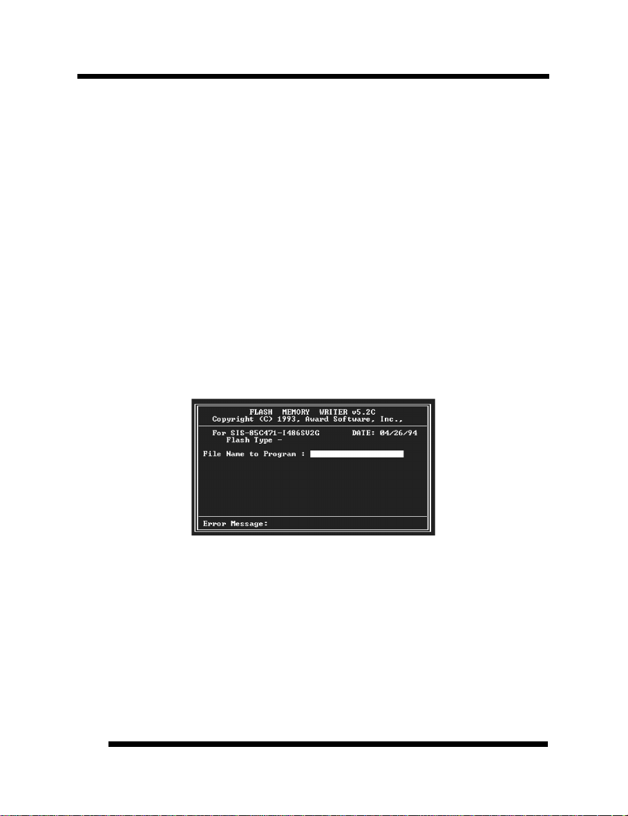
FLASH BIOS PROGRAMMING UTILITY
Updating the Award BIOS Code is made easy with the AWDFLASH Utility. Since this
mainboard features FLASH BIOS, it is not necessary to change the actual BIOS chip in
order to upgrade the System BIOS. The user can simply re-program the old BIOS using the
AWDFLASH Utility as follows:
1. First, boot the system with DOS or to “Safe Mode” under Windows 95. If you are
booting DOS from a hard drive or floppy disk, press [F5] when the message “Starting
MS-DOS…” appears on the screen. If you are booting Windows 95, press the [F8] key,
and select the “Safe mode command prompt” option. This will assure that the system is
running in “real mode” with no device drivers loaded. This is the only correct way to
run the AWDFLASH Utility program.
2. There are (2) important files needed to re-program the BIOS. The first is
“AWDFLASH.EXE” which is the FLASH BIOS Programming Utility. The second file
needed is the updated “BIN” file which contains the actual BIOS code. This file will
have the extension [.bin], such as “P598GH.BIN”. Make sure these files are on the
diskette or hard drive in the same directory.
3. Start the AWDFLASH Utility by changing to the directory where the two required files
exist and typing: AWDFLASH and pressing [ENTER].
4. The AWDFLASH Utility Screen appears. You will be asked for the file name to
program. Type in the name of the new BIOS (.bin) file and hit [ENTER].
5. The program will then ask if you want to backup the old BIOS. This is recommended in
case there are any problems with the new “.bin” file. Enter the name of the new backup
file (such as “backup.bin”) and press [ENTER].
6. At this time the system will prompt you for final confirmation before beginning
programming. The Utility can be aborted at this time by hitting “n”. To begin
programming, hit “y”…
7. When the Flash programming starts, a bar indicator will show the progress of the
programming operation. After successful completion, hit the reset button or power off
the computer.
4040
User’s ManualUser’s Manual
Page 41
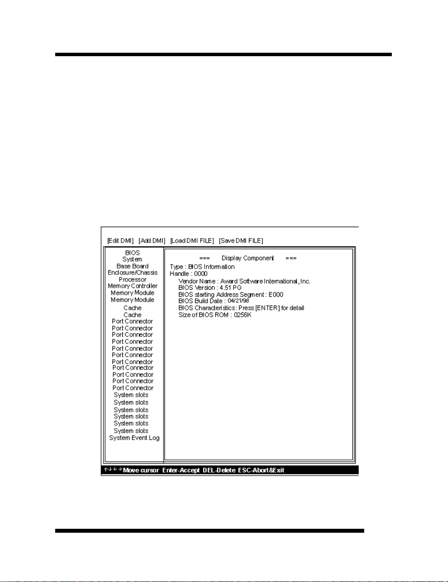
DMI UTILITY
This mainboard supports the Desktop Management Interface (DMI), which is a new
method of providing enterprise management for personal computers. The main component
of DMI is the Management Information Format Database (MIF), which contains information
about the computer system and its components, such as BIOS version/vendor, CPU
speed/type, memory size/type, L1/L2 cache, port connectors (IDE, floppy, 2S/1P, USB,
keyboard, mouse, ), slots … etc. Using DMI, remote PC management software is able to
obtain various information about the system, including hardware profiles, capabilities,
operational status, installation dates, and other information about the system and its
components.
This DMI utility, DMICFG.EXE, allows you to add additional information, such as serial
numbers, vendor information, and enclosure/chassis configurations, into the MIF.
Note: The DMI utility must be run in real mode without the EMM386 memory manager
loaded.
User’s ManualUser’s Manual
4141
Page 42

HARDWARE MONITORING UTILITY
The mainboard has an advanced built-in hardware monitoring feature to keep track of CPU
temperature, system board voltage and CPU fan speed. When an abnormal condition occurs,
the system speaker will BEEP to warn the user to trouble shoot the failed part of the system.
Note:
When an application is using the speaker, the user may LOSE the WARNING BEEP!
The Hardware Monitor utility included with your mainboard is designed for Windows
95/Windows NT. With this utility installed, an error message will pop up under Windows
95/Windows NT in addition to the warning beep to alert the user when problem occurs.
The utility includes the following files:
• MONITOR.EXE Hardware monitor utility
• HMINSTALL.EXE Hardware monitor utility installation program
• Readme file
Installation/Un-installation procedure:
• Run HMINSTALL.EXE under Windows 95/Windows NT to install
MONITOR.EXE to your fixed disk. MONITOR.EXE will then be executed
automatically every time with Windows 95 bootup.
4242
User’s ManualUser’s Manual
 Loading...