

TekPower DT9602R Operation Manual

Model DT9602R
6000 COUNT AUTO RANGE & AUTO POWER OFF DIGITAL MULTIMETER
OPERATION MANUAL
This LCD Auto Range & Auto Power off digital multimeter is a portable, compact ,
6000 COUNT digits with bargraph multimeter . It is ideally suited for field , lab , shop,
car, and home applications.
S afety Information
Warning
To avoid possible electric shock or personal injury, follow these guidelines:
● Do not use the meter if it is damaged. Before you use the meter, inspect the case. Look for
cracks or missing plastic. Pay particular attention to the insulation surrounding the
connectors.
● Inspect the test leads for damaged insulation or exposed metal. Check the test leads for
continuity. Replace damaged test leads before you use the meter.
●The RESPONSIBLE BODY shall be made aware that, if the equipment is used in a manner
not specified by the manufacturer, the protection provided by the equipment may be impaired.
● Do not use the meter if it operates abnormally. Protection may be impaired. When in doubt,
have the meter serviced.
● Do not operate the meter around explosive gas, vapor, or dust.
● Do not apply more than the rated voltage, as marked on the meter, between terminals or
between any terminal and earth ground.
● Before use, verify the meter’s operation by measuring a known voltage.
● When measuring current, turn off circuit power before connecting the meter in the circuit.
Remember to place the meter in series with the circuit.
● When servicing the meter, use only specified replacement parts.
● Use caution when working above 30 V ac rms, 42 V peak, or 60 V dc. Such voltages pose a
shock hazard.
●
The finger or any part of your body shall not be beyond the barrier of the test probe
when measuring.
● Avoid working alone.
● When using the probes, keep your fingers behind the finger guards on the probes.
● Connect the common test lead before you connect the live test lead. When you disconnect
test leads, disconnect the live test lead first.
● Remove test leads from the meter before you open the battery door.
● Do not operate the meter with the battery door or portions of the cover removed or loosened.
● To avoid false readings, which could lead to possible electric shock or personal injury,
replace the batteries as soon as the low battery indicator (
) appears.
● Use only
One standard 9 volt battery (NEDA 1604, IEC 6F22 or equivalent), properly installed
in the meter case, to power the meter.
● To avoid the potential for fire or electrical shock, do not connect the thermocouples to
electrically live circuits.
Caution
To avoid possible damage to the meter or to the equipment under test, follow these guidelines:
● Disconnect circuit power and discharge all high-voltage capacitors before testing resistance,
continuity, diodes, or capacitance.
● Use the proper terminals, function, and range for your measurements.
● Before measuring current, check the meter’s fuses and turn power OFF to the circuit before
connecting the meter to the circuit.
1
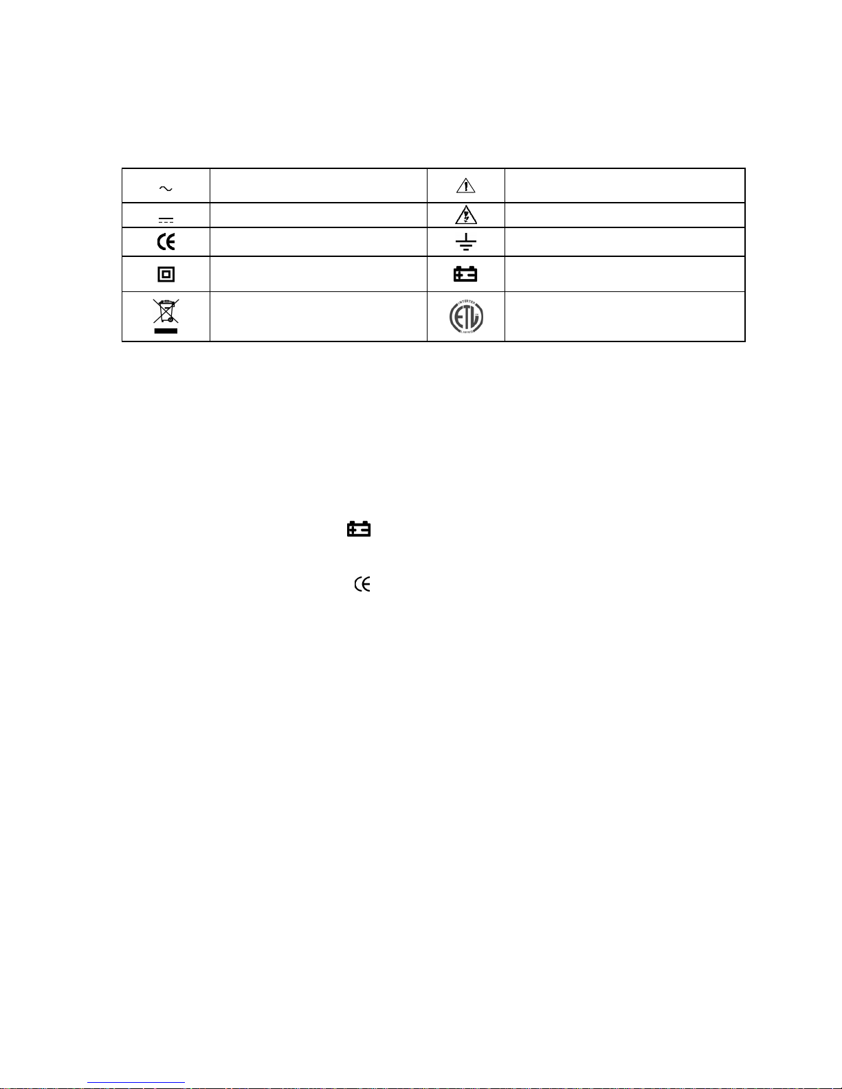
Safety Symbols
Symbols used on the meter and in this manual are explained as below:
International Electrical and Relative Symbols
AC (Alternating Current)
Important information
DC (Direct Current)
Caution risk of electric shock
European Safety Standard
Earth ground
Double insulated
Low Battery Indicator
The symbol indicating separate
collection for electrical and
electronic equipment.
US Safety Standard.
1. SPECIFICATIONS
1.1 GENERAL SPECIFICATIONS
Display : 6000 Count LCD with 62 segments bargraph display, max. reading is
6000.
Range control : Auto range / Manual range control
Polarity : Automatic negative polarity indication.
Zero adjustment : Automatic.
Overrange indication
: The "OL" display.
Lowbattery : The "
" is display when the battery voltage is below 7.5V approx.
Auto Power Off : 15 minutes after stopping the switch, or no any operation for the press
button, the meter automatically enters to power off mode.
Safety standards :
ETL / EMC/LVD. The meter is up to the standards of IEC1010
Pollution Degree 2, Overvoltage CategoryⅡ.
Operating environment: Temperature 32 to104°F (0°C to 40°C), humidity< 80% RH.
Storage environment :Temperature -4 to140°F (-20°C to 60°C), humidity< 90%RH.
Power: One standard 9 volt battery (NEDA 1604 IEC, 6F22 or equivalent)
Dimension: 98(W)×177(H)×39(D) mm
Weight : Approx. 300g (including battery).
1.2 ELECTRICAL SPECIFICATIONS
Accuracy is ± (% of reading + number in last digit) at 23 ± 5°C , <75% RH.
DC Voltage
600mV, 6V, 60V, 600V
: ± (0.5% +5)
1000V : ± (0.8% +5)
Impedance : 10MΩ
Overload protect: 1000V DC or AC 750V RMS.
AC Voltage (True RMS)
6V, 60V, 600V
: ± (0.8% + 5)
750V
: ± (1.2% + 5)
Impedance : 10MΩ.
Frequency response :50~400Hz
Overload protect: 1000V DC or AC 750V RMS.
Resistance
600Ω, 6kΩ, 60kΩ, 600KΩ :± (1% +5)
6MΩ, 60MΩ
:± (2% +5)
2

Overload protection : 250V DC/AC RMS.
DC Current
600µA, 6000µA : ± (2.0% +5)
60mA, 600mA : ± (1.5% +5)
6A ,10A : ± (2% +5)
Overload protect:Fast fuse 0.8A/250V & Fast fuse 10A/250V.
10A for 15sec each 15min maximum.
Input voltage drop
≤: 0.3V.
Note: Not to measure a current in a circuit with voltage more than 250V.
AC Current (True RMS)
600µA, 6000µA
: ± (2.5% +5)
60mA, 600mA : ± (2% +5)
6A ,10A
: ± (2.5% +5)
Overload protect:Fast fuse 0.8A/250V & Fast fuse 10A/250V.
10A for 15sec each 15min maximum.
Input voltage drop
≤: 0.3V.
Frequency Respond: 50Hz - 400Hz
Note: Not to measure a current in a circuit with voltage more than 250V.
Capacitance
40nF : ± (5% +10)
400nF, 4μF, 40μF : ± (3% +5)
400μF, 4000μF
: ± (20% +5)
Overload protection : 250V DC/AC RMS.
Frequency
9.999Hz -10MHz :±(0.1%rdg+5)
Sensitivity: ≤100kHz:1.5V RMS; >100kHz: 5V RMS
Overload protect: 250V RMS
Duty Cycle
0.1~99.9% :± (2% rdg +5)
Overload Protection :250V DC/AC RMS..
Temperature
32°F -- 104°F / 0°C--+40°C
: ±5°F / ±3°C (Use build-in temperature sensor)
-50℃-200℃ :±1.5%±3℃
-58℉-392℉ :±1.5%±5℉
200℃-700℃
:±2%±3℃
392℉-1292℉ :±2%±5℉
Overload protection : 250V DC/AC RMS
Diode Test
Test current :1±0.6mA Test voltage :Approx. 2.8V
Overload protection : 250V DC/AC RMS
Continuity Test
Audible indication: less than 120Ω Approx.
Overload protection : 250V DC/AC RMS.
2. OPERATION
WARNING
1) When measuring voltage ensure that instrument is not connected or switched to resistance
range. Always ensure that the correct terminals are used for the type of measurement to be
made.
3
 Loading...