

Teko Telecom Srl LOWPOWER6 User Manual
www.tekotelecom.it
www.tekotelecom.it
Let us repeat !
SIRIUS: Teko Telecom Modular Coverage and Capacity System
TECHNICAL HANDBOOK
Doc ID Number 91 080 0781 - Rel. 02
english
www.tekotelecom.it
www.tekotelecom.it
Let us repeat !
SIRIUS: Teko Telecom Modular Coverage and Capacity System
BOLOGNA, 11/10/2010
UPDATINGS:
Rel. 02 (11/04/2011)
.........................................
.........................................
Document Identication Number
91 080 0781 – Rel. 02
Doc ID Number 91 080 0781 - Rel. 02
english

www.tekotelecom.it
www.tekotelecom.it
Let us repeat !
Table of Contents
1. Teko Telecom Modular Coverage and Capacity System - General Description ............... 9
1.1 Components ..........................................................................................................................10
1.1.1 Modules providing the RF interface towards the signal source ...................................... 12
1.1.2 Equipment extending coverage / distributing capacity ..................................................... 19
1.1.3 Modules providing the optical interface towards Remote Units .................................... 22
1.1.4 Passive Modules providing distribution and ltering ......................................................... 29
1.1.5 Modules for the management of the System ......................................................................... 34
1.1.6 Power Supply Modules ...................................................................................................................39
1.1.7 Subracks hosting the System modules .....................................................................................41
1.1.8 Forced-air cooling Subrack ............................................................................................................ 43
1.2 Coverage and Capacity Solutions ...................................................................................... 44
1.2.1 Modular O-air Repeaters - General description ..................................................................44
1.2.2 Optical Systems - General Description ...................................................................................... 47
A – Master Unit ...........................................................................................................................................47
B – Remote Units ....................................................................................................................................... 53
1.2.3 Coverage Systems Management and Power Supply ........................................................... 61
1.2.4 Teko Telecom Coverage Systems Technical Specications ................................................ 65
2. System Installation ...................................................................................................................68
2.1 Mechanical Installation ....................................................................................................... 69
2.1.1 Positioning Master Unit Subracks ...............................................................................................71
2.1.2 Positioning Remote Units .............................................................................................................. 72
2.2 Connections ...........................................................................................................................74
2.2.1 RF Connections ..................................................................................................................................75
2.2.2 RS485 Connections ........................................................................................................................103
A – Connecting monitored subracks mounted within the same rack hosting the
Master subrack ........................................................................................................................................104
SIRIUS: Teko Telecom Modular Coverage and Capacity System
B – Connecting remote monitored subracks ................................................................................105
2.2.3 Optical Connections ......................................................................................................................106
A – Connecting Master Unit to Remote Units ...............................................................................107
Doc ID Number 91 080 0781 - Rel. 02
page 3
english

www.tekotelecom.it
www.tekotelecom.it
Let us repeat !
B – Connecting Master point to point Modules to Slave point to point Modules ..........109
2.2.4 Power Supply Connections .........................................................................................................110
A – Active Subracks Power Supply Connection ...........................................................................111
B – Remote Units Power Supply Connection and Alarms Connection ................................114
2.3 Power-Up ..............................................................................................................................117
3. System Commissioning ..........................................................................................................119
4. Preventive Maintenance ........................................................................................................121
4.1 Optical Fibres .......................................................................................................................121
4.2 Remote Units .......................................................................................................................121
4.2.1 Remote Units with passive cooling system (natural convection - fan unit not
equipped) ......................................................................................................................................................121
4.2.2 Remote Units with active cooling system (equipped with the fan unit) ....................121
5. Troubleshooting ......................................................................................................................124
5.1 Troubleshooting procedures ............................................................................................128
5.1.1 Active RF Interface Modules .......................................................................................................128
A – Digital Donor Front End module - MU-DFE ............................................................................128
B – Point of Interface module with remote controlled attenuators- TAPOI .......................132
5.1.2 Modules for the management of the System .......................................................................133
5.1.3 Power Supply Modules .................................................................................................................134
5.1.4 Modules providing the optical interface towards Remote Units ..................................135
A – Fiber Optic Transmitter/Receiver modules - MU-OTRX ......................................................135
B – Master and Slave Point to Point modules - MU-PTP ............................................................137
5.1.5 Equipment extending coverage/ distributing capacity ....................................................141
A – Service Front End Subrack ............................................................................................................141
B – Very High/High/Medium power Remote Unit .......................................................................142
C – SFE Subrack / Very High/High/Medium power Remote Unit ampliers ......................145
D – Very High/High/Medium power Remote Unit modules ...................................................147
E – Single/Dual/Triband Low power Remote Unit ......................................................................150
SIRIUS: Teko Telecom Modular Coverage and Capacity System
F – 6-band Low power Remote Unit ................................................................................................154
5.1.6 Forced-air cooling subrack ..........................................................................................................159
Doc ID Number 91 080 0781 - Rel. 02
page 4
english

www.tekotelecom.it
www.tekotelecom.it
Let us repeat !
5.2 Flow charts ...........................................................................................................................160
5.2.1 Received Optical Power out of range - Uplink path ...........................................................161
5.2.2 Received Optical Power out of range - Downlink path ........................................................162
5.3 Replacement Instructions .................................................................................................163
5.3.1 Replacing the fan unit ...................................................................................................................163
5.3.2 Replacing plug-in modules .........................................................................................................164
5.3.3 Extracting guide rails for plug-in modules from active subracks ..................................164
5.3.4 Cleaning optical connectors ......................................................................................................165
SIRIUS: Teko Telecom Modular Coverage and Capacity System
Attached Documents
Safety Rules
Standards
Doc ID Number 91 080 0781 - Rel. 02
page 5
english
www.tekotelecom.it
www.tekotelecom.it
Let us repeat !
Initial Notes
Declaration of Conformity (*)
According to Directive 1999/5/EC (R&TTE)
We TEKO TELECOM hereby declare that the products described in this technical handbook are manufactured by TEKO TELECOM S.p.A. Via
Meucci, 24/a 40024 Castel S. Pietro Terme (Bologna) – ITALY. All the above cited products are compliant with the essential requirements of
article 3 and other relevant provisions of the Radio & Telecommunications Terminal Equipment Directive, n.1999/5/EC, when used for their
intended purpose: improving coverage of mobile communication networks.
Castel S. Pietro Terme (Bologna) – ITALY
Legal representative
Teko Telecom S.p.A.
a Socio Unico
(*) A signed copy of the conformity declaration is available upon request. Please get in touch with our after sale service, lling in the form on
line at the following Internet address: www.tekotelecom.it
Note relevant to product utilization within the European Union (EU)
It’s under user’s own responsibility to verify to be compliant to the National provisions or authorisations required.
For further information refer to: http://ec.europa.eu/enterprise/sectors/rtte/index_en.htm
EU directive 2002/96/EC – WEEE (Waste Electrical and Electronic Equipment)
This product complies with the EU directive 2002/96/EC – WEEE (Waste Electrical and Electronic Equipment)
The symbol of the crossed container marked on the equipment shows that the product, at the end of its
useful life, must be collected separately from other refuse. Therefore the user must deliver the equipment
that has reached the end of its life to the special dierentiated electronic and electrotechnical refuse
collection centres, far subsequent dispatch of the discarded equipment for recycling, treatment and
environmentally compatible disposal, thus contributing in preventing possible negative eects on the
environment and on health and favouring the recycling of the materials from which the equipment is
made.
Illicit disposal of the product by the user will lead to the application of the penalties provided far by the
national legislations of the various Member States on receipt of directive 2002/96/EC.
For further information, please contact our after sales department: www.tekotelecom.it
Packaging and Packaging Waste Directive 94/62/EC
The packaging of the product complies with the Directive 94/62/EC, concerning packaging and packaging waste. Environmentally harmful
materials are not used for packaging.
Packaging is made from materials that can easily be recycled after use. Depending on the means of transportation, the equipment is packed
in a cardboard or wooden box, protected with expanded polystyrene or barrier bags.
The packaging materials are marked according to ISO 11 469.
Please do not throw packaging materials into unsorted waste but separate them according to local regulations waste disposal options.
SIRIUS: Teko Telecom Modular Coverage and Capacity System
Doc ID Number 91 080 0781 - Rel. 02
page 6
english
www.tekotelecom.it
Let us repeat !
www.tekotelecom.it
Operation is subject to the following conditions: (1) this device may not cause interference, and (2) this device must
accept any interference, including interference that may cause undesired operation of the device.
Changes or modications not expressly approved by the party responsible for compliance could void the user’s
authority to operate the equipment.
The antenna(s) used for this transmitter must be installed to provide a separation distance of at least 50 cm for Low Power family in Tri-Band
system (with 8dB of maximum antenna gain for operating bands lower than 1.5GHz and 11dB for operating bands higher than 1.5GHz), at
least 50 cm for Low Power family in Six-Band system (with 4.5dB of maximum antenna gain for operating bands lower than 1.5GHz and 6.5dB
for operating bands higher than 1.5GHz) and at least 150 cm for Very High Power family in Tri-Band System (with 3.5dB of maximum antenna
gain for operating bands lower than 1.5GHz and 6.5dB for operating bands higher than 1.5GHz) from all persons assuming no co-location or
operating in conjuction with any other antenna or transmitter.
With higher maximum gain and/or co-location higher separation distance is required and shall be calculated accordingly by the installer. For
Low Power family in Tri-Band system with 16dB of maximum antenna gain, the separation distance from nearby people shall be 130 cm for
operating bands lower than 1.5GHz, and 90 cm for operating bands higher than 1.5GHz. For Low Power family in Six-Band system with 16dB
of maximum antenna gain, the separation distance from nearby people shall be 190 cm for operating bands lower than 1.5GHz, and 145 cm
for operating bands higher than 1.5GHz. For Very High Power family in Tri-Band system with 16dB of maximum antenna gain, the separation
distance from nearby people shall be 630 cm for operating bands lower than 1.5GHz, and 450 cm for operating bands higher than 1.5GHz.
Specications of antennas, cables, RF components, etc will be provided only in the nal installation phase, being the external antenna not
provided with equipment.
Equipment will be accessible only to maintenance men, that must switch it o before any maintenance operation.
SIRIUS: Teko Telecom Modular Coverage and Capacity System
Teko Telecom Coverage and Capacity Systems Technical Handbook
© Copyright 2010 Teko Telecom S.p.A. All rights reserved.
The content of this manual is for informational use only. Information and specications regarding the products described in this document
are subject to change without notice. The images shown in this document are for illustrative purposes only.
Teko Telecom shall not be liable for technical or editorial errors contained in this manual.
Doc ID Number 91 080 0781 - Rel. 02
page 7
english
www.tekotelecom.it
www.tekotelecom.it
Let us repeat !
1.General Description
SIRIUS: Teko Telecom Modular Coverage and Capacity System
Doc ID Number 91 080 0781 - Rel. 02
english

www.tekotelecom.it
www.tekotelecom.it
Let us repeat !
Teko Telecom Modular Coverage and Capacity System - General 1.
Description
Teko Telecom Coverage and Capacity Systems are exible multi-band multi-operator Systems
that provide a wide range of solutions to extend both indoor and outdoor cellular coverage
in shadow areas -where the RF signal is not available- and to increase capacity in indoor and
outdoor hot spots -where the operators need a dedicated coverage.
Modular design is a key feature of Teko Telecom Coverage and Capacity Systems: it oers
exible conguration options to build the most suitable solution for any coverage need.
SIRIUS
Stand-alone Modular Repeaters, Optical Systems as well as integrated solutions share a unique
common platform: SIRIUS.
SIRIUS includes a wide range of active and passive components that can be assembled in a
variety of ways in order to provide easy to set-up, maintain, and upgrade products operating
in the 380 to 2700MHz frequency range.
SIRIUS components can be used in dierent Systems with dierent functionalities to meet
present needs and to allow system adaptation to changing conditions, always assuring
optimized performances.
Teko Telecom Master Unit is the core of SIRIUS modular design: it is a versatile modular rack-
based platform that controls the whole Coverage System and, depending on its components
conguration, is able to provide:
the RF interface towards the signal source (BTS, Node B, Repeater),•
the RF interface towards Service Antennas/leaky cable,•
the optical interface towards up to 144 Remote Units.•
This technical handbook describes the components of SIRIUS and how these components can
be assembled to provide Optical Systems and Modular O-air Repeaters to improve coverage
in dierent environments.
SIRIUS: Teko Telecom Modular Coverage and Capacity System
Doc ID Number 91 080 0781 - Rel. 02
page 9
english

www.tekotelecom.it
www.tekotelecom.it
Let us repeat !
Components1.1
The components of SIRIUS, Teko Telecom Modular Coverage and Capacity System, can be
grouped in the following categories:
Modules providing the RF interface towards the signal source1.
Point of Interface (POI) module:• it is the single-band/single-operator interface towards
a BTS or NodeB. The Point of Interface module is connected to the signal source via
coaxial cable.
Digital Donor Front End Module: • it is the single-band/single-operator interface
towards a Donor Antenna, providing a connection to a BTS or NodeB over an air link.
Equipment extending coverage / distributing capacity2.
Service Front End:• it is the single-band/multi-operator interface towards a Service
Antenna. It provides wireless signal to the area to be covered (Modular Repeaters).
In Optical Systems the Service Front End can be used to extend coverage to the area
close to the Master Unit site.
Remote Unit:• it is the multi-band/multi-operator equipment used in Optical Systems
to distribute wireless signal throughout the area to be covered (extensive areas
coverage/active DAS).
Modules providing the optical interface towards Remote Units3.
Fiber Optic Transmitter/Receiver Modules• are the optical interface between Master
Unit and Remote Units: they provide RF-to-Optical/Optical-to-RF conversion.
Master and Slave Point to Point Modules • perform the RF-to-Optical/Optical-to-RF
conversion required by the optical point to point link connecting RF Interface modules
to distant Fiber Optic Transmitter/Receiver Modules. The optical point to point link
allows a separation distance -up to 20km- between RF Interface modules and Fiber
Optic Transmitter/Receiver Modules.
Passive Modules providing distribution and ltering4.
Due to the exible conguration options of Teko Telecom Coverage and Capacity Systems,
the same passive components can be used for dierent purposes.
The • 4-way Combiner/Splitter can be used to manage either up to 4 RF interface
modules, operating in the same band (Multi-Operator Systems) or up to 4 Fiber
Optic Modules (Fiber Optic Transmitter/Receiver Modules or Master Point to Point
SIRIUS: Teko Telecom Modular Coverage and Capacity System
Modules).
The • Band Splitter/Combiner (Triplexer) with built-in 1:4 Splitter/Combiner
can be used to manage up to 3 RF interface modules or Service Front End subracks,
Doc ID Number 91 080 0781 - Rel. 02
page 10
english

www.tekotelecom.it
www.tekotelecom.it
Let us repeat !
operating in dierent bands, and up to 4 Fiber Optic Modules. It can also manage
up to 3 four-way splitter/combiner modules each connected to multiple RF interface
modules, operating in the same band, and up to 4 Fiber Optic Modules.
Modules for the management of the System5.
The • Supervision Module allows the management of the whole Coverage System.
The • Alarm Module is an optional module that can be equipped to increase the number
of supported external alarms.
Power Supply Modules6.
The Coverage and Capacity Systems can be equipped with either AC (Universal mains,
85÷264Vac, 50-60Hz) or DC (-72÷-36Vdc) Power Supply modules.
Subracks hosting the System modules7.
Both active and passive subracks are available.
Active subracks• are provided with a backplane that allows the management and
power supply of active modules.
Passive subracks• are used to host passive modules that do not require power nor
management to function. Passive Subracks allow a reduction in the cost of the whole
system.
Forced-air cooling Subrack8.
A forced-air cooling subrack is available to ensure the air ow required for proper cabinet
installed equipment operation.
Rack cabinets for hosting the System Subracks (indoor installation) and cabinets for Outdoor
installation are also available.
A detailed description of each Component of Teko Telecom Modular Coverage and Capacity
System is provided in the following paragraphs.
SIRIUS: Teko Telecom Modular Coverage and Capacity System
Doc ID Number 91 080 0781 - Rel. 02
page 11
english
www.tekotelecom.it
www.tekotelecom.it
Let us repeat !
DL
UL
DL-OUT
-IN
BTS PORT
MONITOR
DL
UL
DL-OUT
-IN
BTS PORT
MONITOR
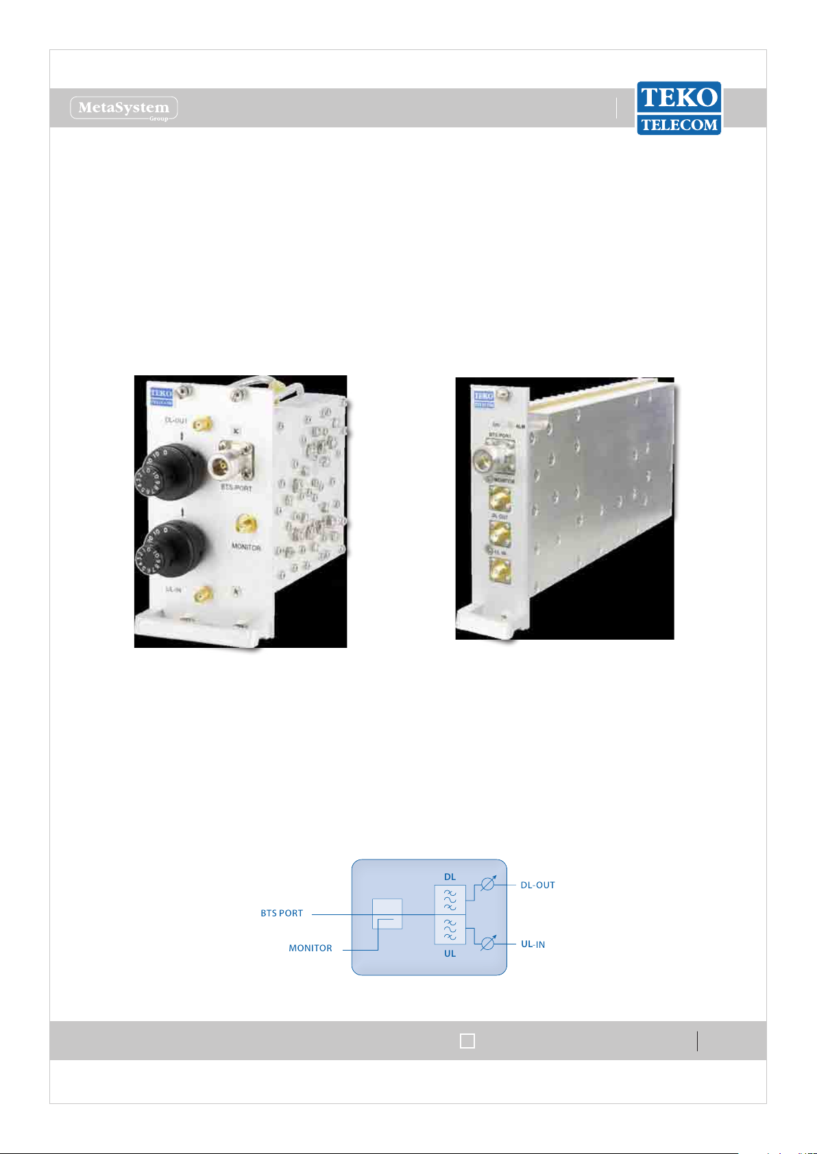
Modules providing the RF interface towards the signal source1.1.1
Point Of Interface Modules•
Point of Interface modules are used in Optical Systems to interface any kind of operator signal
source -pico/micro/macro BTS or NodeB: each Point of Interface module is connected to a
single mobile operator/ mobile band signal source via coaxial cable.
Optical Systems can be equipped with one Point of Interface or more Point of Interface
modules to make multiple congurations available: single operator (single band / multi-band)
and multi-operator (single-band / multi-band).
SIRIUS: Teko Telecom Modular Coverage and Capacity System
Passive Point Of Interface module (POI)
with rotary adjustable attenuators
Point Of Interface module (TAPOI) with
remote-controlled variable attenuators
Each Point of Interface module includes the duplexer, to separate/combine Downlink and
Uplink paths and two variable attenuators to make both Downlink and Uplink RF levels
separately adjustable.
A monitor port is available either for measurements or for external wireless modem
coupling.
UL
Point Of Interface module block diagram
Doc ID Number 91 080 0781 - Rel. 02
page 12
english

www.tekotelecom.it
www.tekotelecom.it
Let us repeat !
Point of Interface modules with separate Downlink and Uplink ports (without built-in duplexer)
are available as option.
Teko Telecom Point of Interface modules can be equipped either with manually adjustable
attenuators (POI-x models) or with remote-controlled attenuators (TAPOI-x models).
POI modules
POI modules include two rotary adjustable attenuators to make Downlink and Uplink RF
levels manually adjustable within a range of either 30dB, with 1dB step, or 10dB, with 1dB
step (POI-A10 models).
TAPOI modules
TAPOI modules include two automated variable attenuators to adjust Downlink and Uplink
RF levels via the Coverage System Supervision Module (TSPV) and Management Tools (OMT
webpages, OMC software).
SIRIUS: Teko Telecom Modular Coverage and Capacity System
Doc ID Number 91 080 0781 - Rel. 02
page 13
english

www.tekotelecom.it
www.tekotelecom.it
Let us repeat !
POI Modules Access Points•
Adjustable
attenuators
Passive POI with built-in duplexer Passive POI without built-in duplexer
Adjustable
attenuators
Label
(Connectors)
DL-OUT
UL-IN
BTS PORT
MONITOR
Adjustable
Description
Downlink path RF output
(SMA connector)
Uplink path RF input (SMA
connector)
RF connector (N type )
towards the signal source
(BTS, Node B or repeater)
Monitor port for
measurements or for external
wireless modem coupling
Description
Label
(Connectors)
DL-OUT
UL-IN
BTS PORT DL
BTS PORT UL
Description
Downlink path RF output
SMA connector
Uplink path RF input SMA
connector
Input RF connector from the
signal source - BTS, Node B
or repeater (N type)
Output RF connector to the
signal source - BTS, Node B
or repeater (N type)
attenuators
DL OUT Downlink path RF level adjustable attenuator (0÷30dB or 0÷10dB - 1 dB step)
UL IN Uplink path RF level adjustable attenuator (0÷30dB or 0÷10dB - 1 dB step)
SIRIUS: Teko Telecom Modular Coverage and Capacity System
Doc ID Number 91 080 0781 - Rel. 02
page 14
english
www.tekotelecom.it
www.tekotelecom.it
Let us repeat !
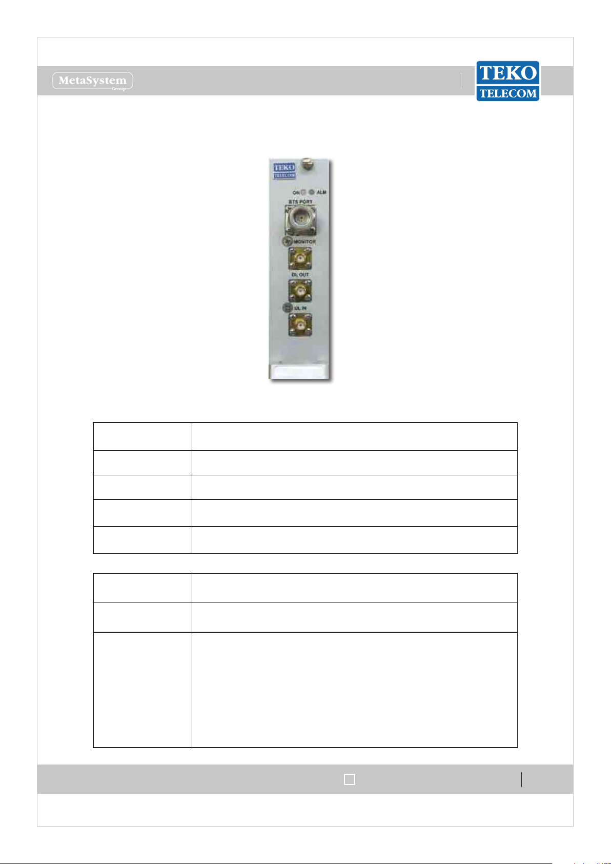
TAPOI Modules Access Points•
TAPOI with built-in duplexer
Label
Description
(Connectors)
DL OUT Downlink path RF output (SMA connector)
UL IN Uplink path RF input (SMA connector)
BTS PORT
MONITOR
Label
RF connector (N type ) towards the signal source (BTS, Node B
or repeater)
Monitor port for measurements or for external wireless modem
coupling
Description
(LEDs)
ON
TAPOI Module operating status green LED
ON when power supply is present
TAPOI Module alarm status LED:
OFF: regular operation
Blinking Orange: presence of active alarms with warning
ALM
severity level (4)
Orange: presence of active alarms with minor severity level (3)
Blinking Red: presence of active alarms with major severity
level (2)
Red: presence of active alarms with critical severity level (1)
SIRIUS: Teko Telecom Modular Coverage and Capacity System
Doc ID Number 91 080 0781 - Rel. 02
page 15
english

www.tekotelecom.it
www.tekotelecom.it
Let us repeat !
Teko Telecom Digital Donor Front End•
The Digital Donor Front End Module is the single-band/single-operator System RF interface
towards a Donor Antenna. No physical connections are required between the DFE and the
cellular network: the Donor Antenna provides the connection to a BTS or NodeB over an air
link.
Coverage Systems can be equipped with one or more Donor Front End modules to make
multiple congurations available: single operator (single band / multi-band) and multi-
operator (single-band / multi-band).
SIRIUS: Teko Telecom Modular Coverage and Capacity System
A single-band single-operator modular O-air Repeater can be set up combining a Digital
Donor Front End Module and a Service Front End (Teko Telecom single-band/multi-operator
interface towards a Service Antenna). Up to 4 Donor Front End Modules can be connected to
a single Service Front End to provide a single-band 4-operator modular O-air Repeater.
Digital Donor Front End Modules can also be used to drive Optical Systems: the Digital Donor
Front End Module allows Optical Systems to be driven without the need of a dedicated BTS or
Node B. A donor antenna picks-up the signal and the Optical System acts as a repeater with
distributed Service antennas connected to the Remote Units. Service Front End subracks can
be connected to DFE modules to provide coverage to the area next to the Master Unit site.
Doc ID Number 91 080 0781 - Rel. 02
page 16
english
www.tekotelecom.it
www.tekotelecom.it
Let us repeat !
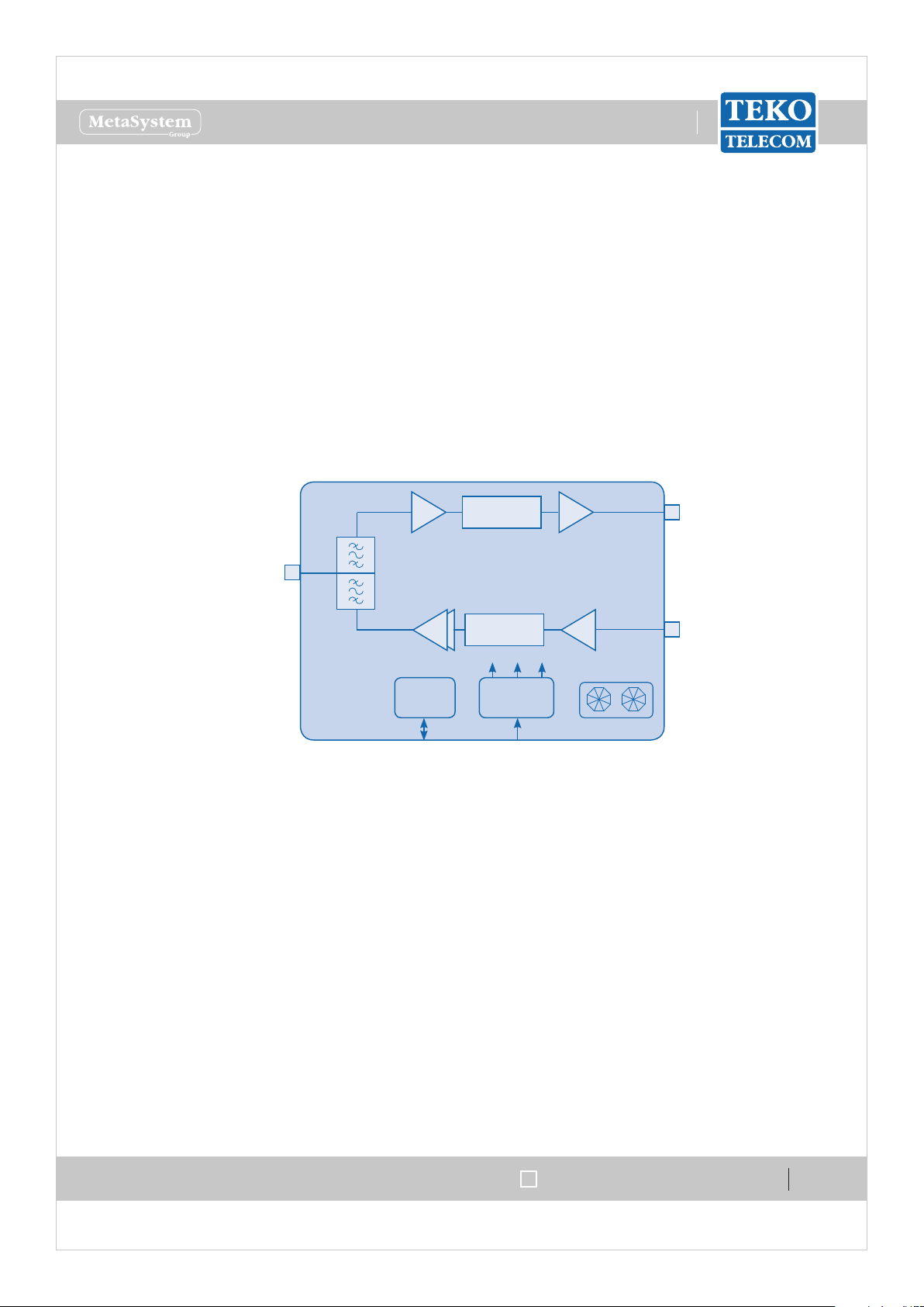
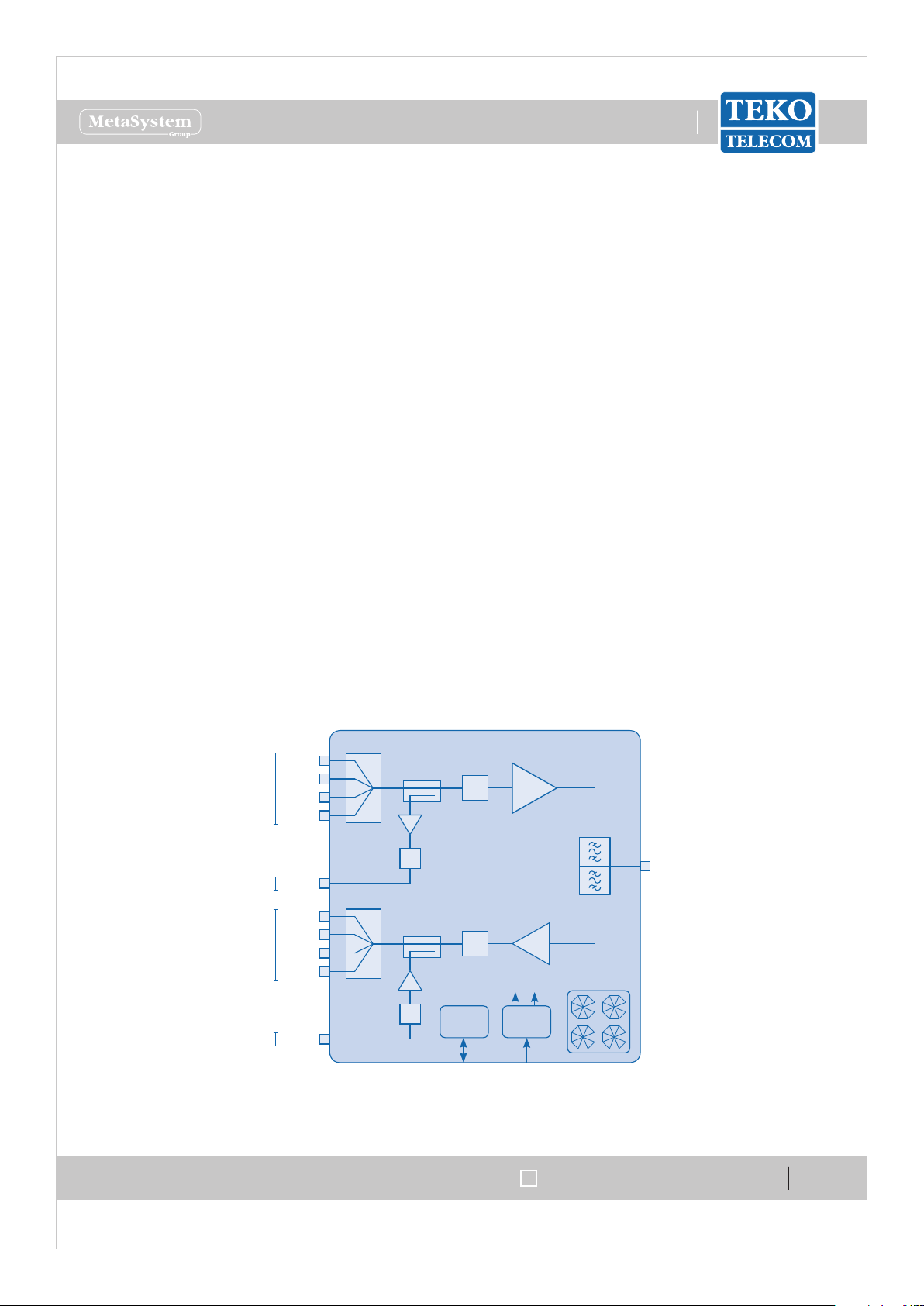
Each DFE module hosts the duplexer, to be connected to the Donor Antenna to separate/
combine downlink and uplink paths.
In downlink the signal from the Donor Antenna is preamplied by a Low Noise Amplier and
converted into an IF signal by a downconverter. The selection of the band of frequencies or
channels to be extended is handled by a digital lter.
The digital lter can manage 1 variable band or 2 variable sub-bands.
An upconverter converts the IF signal into the RF output signal.
In uplink the signal from the Service Front End Subrack or from the Optical System is converted
into an IF signal by a downconverter, ltered and re-converted into an RF signal, amplied by
a power amplier and re-transmitted to the signal source.
DL RF
Out
Donor
Antenna
Port
DUPLEXER
LNA
DIGITAL FILTER
UL RF
PA
DIGITAL FILTER
+12V +1.8V+3.3V
P DC/DC
RS485
28VDC
In
FANS
Digital Donor Front End Module block diagram
SIRIUS: Teko Telecom Modular Coverage and Capacity System
Doc ID Number 91 080 0781 - Rel. 02
page 17
english

www.tekotelecom.it
www.tekotelecom.it
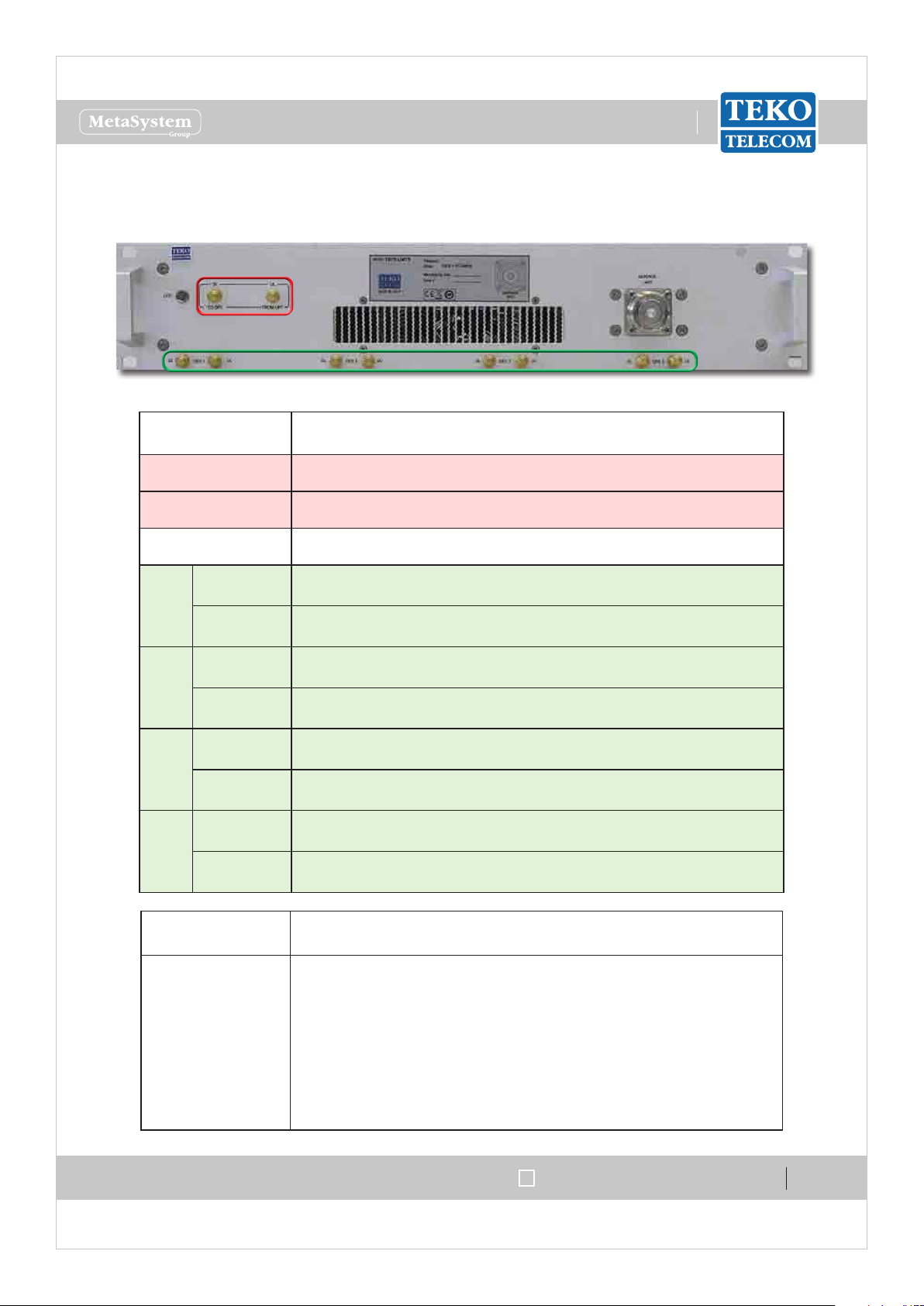
Digital Donor Front End Module Access Points
Let us repeat !
Label
Description
(Connectors)
DL
UL
Downlink path RF output (SMA connector) to Service Front End
or Fiber Optic Modules
Uplink path RF input (SMA connector) from Service Front End
or Fiber Optic Modules
DONOR ANT Donor Antenna Port (N type connector)
Label
Description
(LEDs)
ON
Digital Donor Front End Module operating status green LED:
ON when power supply is present
Digital Donor Front End Module alarm status LED:
OFF: regular operation
Blinking Orange: presence of active alarms with warning
ALM
severity level (4)
Orange: presence of active alarms with minor severity level (3)
Blinking Red: presence of active alarms with major severity
level (2)
Red: presence of active alarms with critical severity level (1)
SIRIUS: Teko Telecom Modular Coverage and Capacity System
Doc ID Number 91 080 0781 - Rel. 02
page 18
english
www.tekotelecom.it
www.tekotelecom.it
Let us repeat !
Equipment extending coverage / distributing capacity1.1.2
Teko Telecom Service Front End•
Teko Telecom Service Front End Subrack is a single-band/multi operator equipment, driven
by Digital Donor Front End Modules and connected to a Service Antenna to provide wireless
signal to the area to be covered. The equipment is available in four dierent power classes:
Very High, High, Medium and Low.
A single-band single-operator modular O-air Repeater can be set-up combining a Digital
Donor Front End Module and a Service Front End. Up to 4 Donor Front End Modules can
be connected to a single Service Front End subrack to provide a single-band 4-operator
Repeater.
The Service Front End subrack can also be used in Optical Systems to provide coverage to the
area adjoining the Master Unit site.
The SFE 19”/2U subrack hosts the duplexer, to be connected to the Service Antenna to
separate/combine Downlink and Uplink paths.
In Downlink the signals from the Donor Front-End Modules are combined and amplied by a
Power Amplier.
In Uplink, the RF signal from the Service antenna is amplied by a Low Noise Amplier (LNA)
and split to feed up to 4 Donor Front-End Modules.
Auxiliary ports are available to drive an Optical System.
From DFEs
To Optics
To DFEs
From Optics
DL in1
DL in2
DL in3
DL in4
DL out
UL out1
UL out2
UL out3
UL out4
UL in
4:1
Digital
Attenuator
4:1
Digital
Attenuator
Digital
Attenuator
Digital
Attenuator
+3.3V +5V
P DC/DC
RS485
PA
Service
Duplexer
LNA
FANS
28VDC
Antenna
Port
SIRIUS: Teko Telecom Modular Coverage and Capacity System
Service Front End Module block diagram
Doc ID Number 91 080 0781 - Rel. 02
page 19
english
www.tekotelecom.it
www.tekotelecom.it
Service Front End Module Access Points
Let us repeat !
Label
Description
(Connectors)
DL TO OPT Downlink path RF output (SMA connector) - to Optics
UL FROM OPT Uplink path RF input (SMA connector) - from Optics
SERVICE ANT Service Antenna Port (N type )
DL
DFE1
UL
DL
DFE2
UL
DL
DFE3
UL
DL
DFE4
UL
Downlink path RF input (SMA connector) - from Digital Donor
Front End 1
Uplink path RF output (SMA connector) - to Digital Donor Front
End 1
Downlink path RF input (SMA connector) - from Digital Donor
Front End 2
Uplink path RF output (SMA connector) - to Digital Donor Front
End 2
Downlink path RF input (SMA connector) - from Digital Donor
Front End 3
Uplink path RF output (SMA connector) - to Digital Donor Front
End 3
Downlink path RF input (SMA connector) - from Digital Donor
Front End 4
Uplink path RF output (SMA connector) - to Digital Donor Front
End 4
SIRIUS: Teko Telecom Modular Coverage and Capacity System
Label
(LEDs)
LED
Description
Service Front End subrack general operating status LED
Green: no alarm
Blinking Orange: presence of active alarms with warning
severity level (4)
Orange: presence of active alarms with minor severity level (3)
Blinking Red: presence of active alarms with major severity
level (2)
Red: presence of active alarms with critical severity level (1)
Doc ID Number 91 080 0781 - Rel. 02
page 20
english
 Loading...