

Teko Telecom VHPA, DFE Users Manual
www.tekotelecom.it
www.tekotelecom.it
Let us repeat !
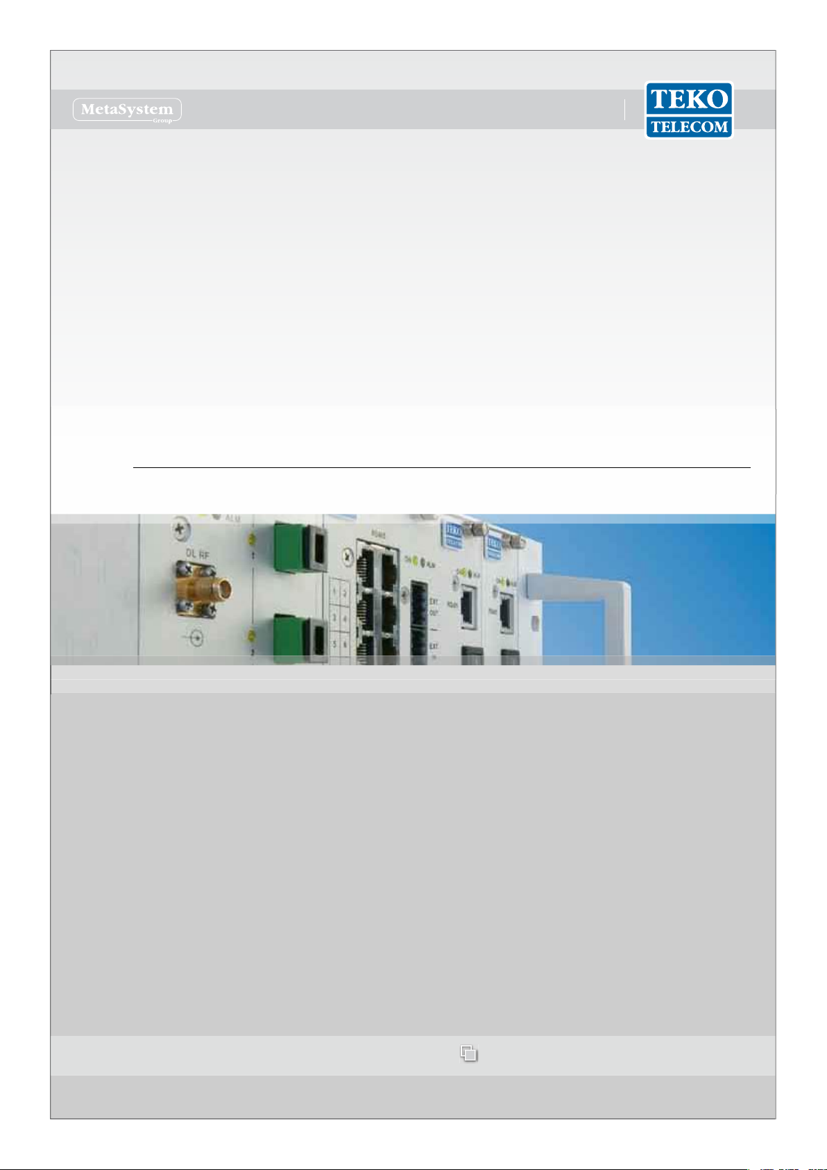
SIRIUS: Teko Telecom Modular Coverage and Capacity System
TECHNICAL HANDBOOK
Doc ID Number 91 080 0781 - Rel. 04
english
www.tekotelecom.it
www.tekotelecom.it
Let us repeat !
english
Doc ID Number 91 080 0781 - Rel. 04
BOLOGNA, 11/10/2010
UPDATINGS:
Rel. 02 (11/04/2011)
Rel. 03 (15/03/2012)
Rel. 04 (11/06/2012)
Document Identication Number
91 080 0781 – Rel. 04
SIRIUS: Teko Telecom Modular Coverage and Capacity System

www.tekotelecom.it
www.tekotelecom.it
SIRIUS: Teko Telecom Modular Coverage and Capacity System
Let us repeat !
Doc ID Number 91 080 0781 - Rel. 04 page 3
english
Table of Contents
1. Teko Telecom Modular Coverage and Capacity System - General Description .............10
1.1 Components ..........................................................................................................................11
1.1.1 Modules providing the RF interface towards the signal source ...................................... 13
1.1.2 Equipment extending coverage / distributing capacity ..................................................... 20
1.1.3 Modules providing the optical interface towards Remote Units .................................... 23
1.1.4 Passive Modules providing distribution and ltering ......................................................... 30
1.1.5 Modules for the management of the System ......................................................................... 39
1.1.6 Power Supply Modules ...................................................................................................................44
1.1.7 Subracks hosting the System modules .....................................................................................46
1.1.8 Forced-air cooling Subrack ............................................................................................................ 47
1.2 Coverage and Capacity Solutions ...................................................................................... 48
1.2.1 Modular O-air Repeaters - General description ..................................................................48
1.2.2 Optical Systems - General Description ...................................................................................... 51
A – Master Unit ...........................................................................................................................................51
B – Remote Units ....................................................................................................................................... 57
1.2.3 Coverage Systems Management and Power Supply ........................................................... 65
1.2.4 Teko Telecom Coverage Systems Technical Specications ................................................ 69
2. System Installation ...................................................................................................................72
2.1 Mechanical Installation ....................................................................................................... 73
2.1.1 Positioning Master Unit Subracks ...............................................................................................75
2.1.2 Positioning Remote Units .............................................................................................................. 76
2.2 Connections ...........................................................................................................................79
2.2.1 RF Connections ..................................................................................................................................80
2.2.2 RS485 Connections ........................................................................................................................111
A – Connecting monitored subracks mounted within the same rack hosting the Master
subrack .......................................................................................................................................................112
B – Connecting remote monitored subracks ................................................................................113
2.2.3 Optical Connections ......................................................................................................................114
A – Connecting Master Unit to Remote Units ...............................................................................115

www.tekotelecom.it
www.tekotelecom.it
SIRIUS: Teko Telecom Modular Coverage and Capacity System
Let us repeat !
Doc ID Number 91 080 0781 - Rel. 04 page 4
english
B – Connecting Master point to point Modules to Slave point to point Modules ..........117
2.2.4 Power Supply and External Alarms connections .................................................................118
A – Active Subracks Power Supply Connection ...........................................................................119
B – Very High/High/Medium Power Remote Unit External Alarms Connection ..............122
C – Remote Units Power Supply Connection ................................................................................123
2.3 Power-Up ..............................................................................................................................126
3. System Commissioning ..........................................................................................................128
4. Preventive Maintenance ........................................................................................................130
4.1 Optical Fibres .......................................................................................................................130
4.2 Remote Units .......................................................................................................................130
4.2.1 Remote Units with passive cooling system (natural convection - fan unit not
equipped) ......................................................................................................................................................130
4.2.2 Remote Units with active cooling system (equipped with the fan unit) ....................130
5. Troubleshooting ......................................................................................................................133
5.1 Troubleshooting procedures ............................................................................................137
5.1.1 Active RF Interface Modules .......................................................................................................137
A – Digital Donor Front End module - MU-DFE ............................................................................137
B – Point of Interface module with remote controlled attenuators- TAPOI .......................141
5.1.2 Modules for the management of the System .......................................................................142
5.1.3 Power Supply Modules .................................................................................................................143
5.1.4 Modules providing the optical interface towards Remote Units ..................................144
A – Fiber Optic Transmitter/Receiver modules - MU-OTRX ......................................................144
B – Master and Slave Point to Point modules - MU-PTP ............................................................146
5.1.5 Equipment extending coverage/ distributing capacity ....................................................150
A – Service Front End Subrack ............................................................................................................150
B – Very High/High/Medium power Remote Unit .......................................................................151
C – SFE Subrack / Very High/High/Medium power Remote Unit ampliers ......................154
D – Very High/High/Medium power Remote Unit modules ...................................................156
E – Single/Dual/Triband Low power Remote Unit ......................................................................159
F – 5-band/6-band Low power Remote Unit ................................................................................163

www.tekotelecom.it
www.tekotelecom.it
SIRIUS: Teko Telecom Modular Coverage and Capacity System
Let us repeat !
Doc ID Number 91 080 0781 - Rel. 04 page 5
english
5.1.6 Forced-air cooling subrack ..........................................................................................................168
5.2 Flow charts ...........................................................................................................................169
5.2.1 Received Optical Power out of range - Uplink path ...........................................................170
5.2.2 Received Optical Power out of range - Downlink path .....................................................171
5.3 Replacement Instructions .................................................................................................172
5.3.1 Replacing the fan unit ...................................................................................................................172
5.3.2 Replacing plug-in modules .........................................................................................................173
5.3.3 Extracting guide rails for plug-in modules from active subracks ..................................173
5.3.4 Cleaning optical connectors ......................................................................................................174
Attached Documents
Safety Rules
Standards
www.tekotelecom.it
www.tekotelecom.it
SIRIUS: Teko Telecom Modular Coverage and Capacity System
Let us repeat !
Doc ID Number 91 080 0781 - Rel. 04 page 6
english
Initial Notes
Declaration of Conformity (*)
According to Directive 1999/5/EC (R&TTE)
We TEKO TELECOM hereby declare that the products described in this technical handbook are manufactured by TEKO TELECOM S.p.A. Via
Meucci, 24/a 40024 Castel S. Pietro Terme (Bologna) – ITALY. All the above cited products are compliant with the essential requirements of
article 3 and other relevant provisions of the Radio & Telecommunications Terminal Equipment Directive, n.1999/5/EC, when used for their
intended purpose: improving coverage of mobile communication networks.
Castel S. Pietro Terme (Bologna) – ITALY
Legal representative
Teko Telecom S.p.A.
a Socio Unico
(*) A signed copy of the conformity declaration is available upon request. Please get in touch with our after sale service, lling in the form on
line at the following Internet address: www.tekotelecom.it
Note relevant to product utilization within the European Union (EU)
It’s under user’s own responsibility to verify to be compliant to the National provisions or authorisations required.
For further information refer to: http://ec.europa.eu/enterprise/sectors/rtte/index_en.htm
EU directive 2002/96/EC – WEEE (Waste Electrical and Electronic Equipment)
This product complies with the EU directive 2002/96/EC – WEEE (Waste Electrical and Electronic Equipment)
The symbol of the crossed container marked on the equipment shows that the product, at the end of its
useful life, must be collected separately from other refuse. Therefore the user must deliver the equipment
that has reached the end of its life to the special dierentiated electronic and electrotechnical refuse
collection centres, far subsequent dispatch of the discarded equipment for recycling, treatment and
environmentally compatible disposal, thus contributing in preventing possible negative eects on the
environment and on health and favouring the recycling of the materials from which the equipment is
made.
Illicit disposal of the product by the user will lead to the application of the penalties provided far by the
national legislations of the various Member States on receipt of directive 2002/96/EC.
For further information, please contact our after sales department: www.tekotelecom.it
Packaging and Packaging Waste Directive 94/62/EC
The packaging of the product complies with the Directive 94/62/EC, concerning packaging and packaging waste. Environmentally harmful
materials are not used for packaging.
Packaging is made from materials that can easily be recycled after use. Depending on the means of transportation, the equipment is packed
in a cardboard or wooden box, protected with expanded polystyrene or barrier bags.
The packaging materials are marked according to ISO 11 469.
Please do not throw packaging materials into unsorted waste but separate them according to local regulations waste disposal options.
www.tekotelecom.it
www.tekotelecom.it
SIRIUS: Teko Telecom Modular Coverage and Capacity System
Let us repeat !
Doc ID Number 91 080 0781 - Rel. 04 page 7
english
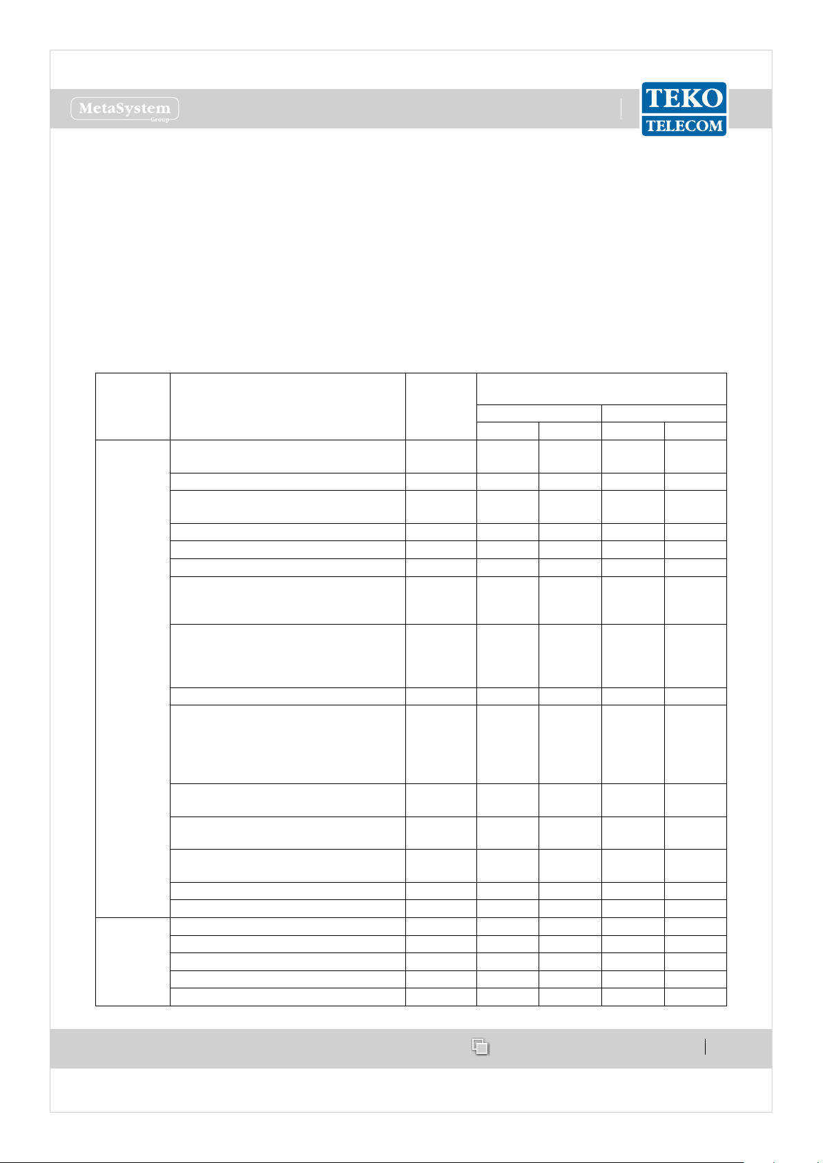
Compliance with the Maximum Permissible Exposure (MPE) limits - Examples of minimum separation
distance calculation, based on the EN 50385
The following table summarizes the results of the calculations carried out assuming:
zero losses between the output connector of Teko Telecom equipment and the input connector of the antenna•
maximum gain estimated for outdoor Antenna Gi = 19dBi (for each band)•
maximum gain estimated for indoor Antenna Gi = 7dBi (for each band)•
no co-location or operation• in conjunction with any other antenna or transmitter.
Please note
The following table is not meant to represent the actual compliance distance from a particular Teko Telecom Optical System or Modular
Repeater, being antennas, cables, and other RF components not provided with Teko Telecom equipment.
The actual compliance distance from a particular equipment can be calculated in the nal installation phase only - when antenna, cables and
other RF components specications are available.
Equipment Type Maximum
Output
Power
Minimum separation distance between a person and
the antenna in order to comply with MPE limits [m]
Indoor installation Outdoor installation
E=6 [V/m] E=20 [V/m] E=6 [V/m] E=20 [V/m]
Remote Unit
and
Service Front
End (TSFE)
Low Power Single band Remote Units•
Medium Power EGSM band Remote Unit•
29dBm 1.8 0.6 7.1 2.3
Medium Power DCS band Remote Unit 31dBm 2.2 0.7 8.9 2.8
Low Power Dual band Remote Units•
Medium Power UMTS band Remote Unit•
32dBm 2.5 0.8 10.1 3.2
Triband Low Power Remote Units 33.8dBm 3.1 1.0 12.3 3.9
Dual band Medium Power Remote Units 34.6dBm 3.4 1.1 13.4 4.2
Medium Power Triband Remote Units 35.6dBm 3.8 1.5 15.2 4.8
Low Power 5-band Remote Unit•
High Power TETRA Remote Unit•
High Power TETRA Service Front End•
36dBm 4.0 1.3 15.9 5.0
High Power Single band Remote Units (LTE800 •
or EGSM or DCS or UMTS)
High Power Service Front End (LTE800 or EGSM •
or DCS or UMTS or LTE2600)
40dBm 6.3 2.0 25.1 8.0
High Power Single band Remote Unit (LTE2600) 41dBm 7.1 2.2 28.1 8.9
High Power Dual band Remote Units (LTE800 •
and/or EGSM and/or DCS and/or UMTS)
Very High Power Single band Remote Units•
Very High Power Service Front End (LTE800 or •
EGSM or DCS or UMTS)
43dBm 8.9 2.8 35.6 11.2
High Power Dual Band Remote Units (LTE800 or
EGSM or DCS or UMTS with LTE2600)
43.5dBm 9.5 3.0 37.7 11.9
High Power Tri Band Remote Units (LTE800 and/or
EGSM and/or DCS and/or UMTS)
44.7dBm 10.9 3.5 43.6 13.8
High Power Tri Band Remote Units (LTE800 or
EGSM or DCS or UMTS with LTE2600)
45.1dBm 11.4 3.6 45.3 14.3
Very High Power Dual Band Remote Units 46dBm 12.6 4.0 50.3 15.9
Very High Power Tri Band Remote Units 47.8dBm 15.5 4.9 61.6 19.5
Donor Front
End
(TDFE)
Single Band TETRA Donor Front End 21dBm 0.7 0.2 2.8 0.9
Single Band EGSM Donor Front End 23dBm 0.9 0.3 3.6 1.1
Single Band DCS Donor Front End 25dBm 1.1 0.4 4.5 1.4
Single Band LTE 800 or LTE2600 Donor Front End 26dBm 1.3 0.4 5.0 1.6
Single Band UMTS Donor Front End 27dBm 1.4 0.5 5.6 1.8
www.tekotelecom.it
www.tekotelecom.it
Let us repeat !
Operation is subject to the following conditions: (1) this device may not cause interference, and (2) this device must
accept any interference, including interference that may cause undesired operation of the device.
Changes or modications not expressly approved by the party responsible for compliance could void the user’s
authority to operate the equipment.
The antenna(s) used for this transmitter must be installed to provide a separation distance of:
at least 50cm for Low Power Remote Units family in Tri-Band system (with 8dB of maximum antenna gain for operating bands lower than •
1.5GHz and 11dB for operating bands higher than 1.5GHz),
at least 50cm for Low Power Remote Units family in Six-Band system (with 4.5dB of maximum antenna gain for operating bands lower •
than 1.5GHz and 6.5dB for operating bands higher than 1.5GHz),
at least 150cm for Very High Power Remote Units family in Tri-Band System (with 3.5dB of maximum antenna gain for operating bands •
lower than 1.5GHz and 6.5dB for operating bands higher than 1.5GHz)
at least 50cm for Donor Front End family (with 15.5dB of maximum antenna gain for operating bands lower than 1.5GHz and 19dB for •
operating bands higher than 1.5GHz),
at least 150cm for Very High Power Amplier radio module, equipped inside Service Front End family and Very High Power Remote •
Units family (with 8dB of maximum antenna gain for operating bands lower than 1.5GHz and 11.5dB for operating bands higher than
1.5GHz)
from all persons assuming no co-location or operating in conjuction with any other antenna or transmitter.
Specications of antennas, cables, RF components, etc will be provided only in the nal installation phase, being the external antenna not
provided with equipment.
Equipment will be accessible only to maintenance men, that must switch it o before any maintenance operation.
SIRIUS: Teko Telecom Modular Coverage and Capacity System
Teko Telecom Coverage and Capacity Systems Technical Handbook
© Copyright 2010-2012 Teko Telecom S.p.A. All rights reserved.
The content of this manual is for informational use only. Information and specications regarding the products described in this document
are subject to change without notice. The images shown in this document are for illustrative purposes only.
Teko Telecom shall not be liable for technical or editorial errors contained in this manual.
Doc ID Number 91 080 0781 - Rel. 04 page 8
english
www.tekotelecom.it
www.tekotelecom.it
Let us repeat !
english
Doc ID Number 91 080 0781 - Rel. 04
SIRIUS: Teko Telecom Modular Coverage and Capacity System

www.tekotelecom.it
www.tekotelecom.it
SIRIUS: Teko Telecom Modular Coverage and Capacity System
Let us repeat !
Doc ID Number 91 080 0781 - Rel. 04 page 10
english
Teko Telecom Modular Coverage and Capacity System - General 1.
Description
Teko Telecom Coverage and Capacity Systems are exible multi-band multi-operator Systems
that provide a wide range of solutions to extend both indoor and outdoor cellular coverage
in shadow areas -where the RF signal is not available- and to increase capacity in indoor and
outdoor hot spots -where the operators need dedicated coverage.
Modular design is a key feature of Teko Telecom Systems: it oers exible conguration
options to build the most suitable solution for any coverage need.
SIRIUS
Stand-alone Modular Repeaters, Optical Systems as well as integrated solutions share a unique
common platform: SIRIUS.
SIRIUS includes a wide range of active and passive components that can be assembled in a
variety of ways in order to provide easy to set-up, maintain, and upgrade products operating
in the 380 to 2700MHz frequency range.
SIRIUS components can be used in dierent Systems with dierent functionalities to meet
present needs and to allow system adaptation to changing conditions, always assuring
optimized performances.
Teko Telecom Master Unit is the core of SIRIUS modular design: it is a versatile modular rack-
based platform that controls the whole Coverage System and, depending on its components
conguration, is able to provide:
the RF interface towards the signal source (BTS, Node B, Repeater),•
the RF interface towards Service Antennas/leaky cable,•
the optical interface towards up to 144 Remote Units.•
This technical handbook describes the components of SIRIUS and how these components can
be assembled to provide Optical Systems and Modular O-air Repeaters to improve coverage
in dierent environments.

www.tekotelecom.it
www.tekotelecom.it
SIRIUS: Teko Telecom Modular Coverage and Capacity System
Let us repeat !
Doc ID Number 91 080 0781 - Rel. 04 page 11
english
Components1.1
The components of SIRIUS can be grouped in the following categories:
Modules providing the RF interface towards the signal source1.
Point of Interface (POI) module:• is the single-band/single-operator interface towards
a BTS or NodeB. The Point of Interface module is connected to the signal source via
coaxial cable.
Digital Donor Front End Module: • is the single-band/single-operator interface towards
a Donor Antenna, providing a connection to a BTS or NodeB over an air link.
Equipment extending coverage / distributing capacity2.
Service Front End:• is the single-band/multi-operator interface towards a Service
Antenna. It provides wireless signal to the area to be covered (Modular Repeaters).
In Optical Systems the Service Front End can be used to extend coverage to the area
close to the Master Unit site.
Remote Unit:• is the multi-band/multi-operator equipment used in Optical Systems to
distribute wireless signal throughout the area to be covered (extensive areas coverage/
active DAS).
Modules providing the optical interface towards Remote Units3.
Fiber Optic Transmitter/Receiver Modules• are the optical interface between Master
Unit and Remote Units: they provide RF-to-Optical/Optical-to-RF conversion.
Master and Slave Point to Point Modules • perform the RF-to-Optical/Optical-to-RF
conversion required by the optical point to point link connecting RF Interface modules
to distant Fiber Optic Transmitter/Receiver Modules. The optical point to point link
allows a separation distance -up to 20km- between RF Interface modules and Fiber
Optic Transmitter/Receiver Modules.
Passive Modules providing distribution and ltering4.
Our passive components provide RF distribution and ltering.
The 4-way Combiner/Splitter can be used to manage up to 4 RF interface modules
operating in the same band; several models of Triplexers with built-in 1:4 Splitter/Combiner
are available to distribute signals operating over up to 3 dierent bands. The multiplexers
distribute signals operating over multiple dierent bands - up to 5 (pentaplexer); up to 6
(esaplexer).
Due to the exible conguration options of Teko Telecom Coverage and Capacity Systems,
the same passive components can be used for dierent purposes.
The • 4-way Combiner/Splitter can be used to manage either up to 4 RF interface

www.tekotelecom.it
www.tekotelecom.it
SIRIUS: Teko Telecom Modular Coverage and Capacity System
Let us repeat !
Doc ID Number 91 080 0781 - Rel. 04 page 12
english
modules, operating in the same band (Multi-Operator Systems) or up to 4 Fiber
Optic Modules (Fiber Optic Transmitter/Receiver Modules or Master Point to Point
Modules).
The • Band Splitter/Combiner (Triplexer) with built-in 1:4 Splitter/Combiner
can be used to manage up to 3 RF interface modules or Service Front End subracks,
operating in dierent bands, and up to 4 Fiber Optic Modules. It can also manage
up to 3 four-way splitter/combiner modules each connected to multiple RF interface
modules, operating in the same band, and up to 4 Fiber Optic Modules.
Modules for the management of the System5.
The • Supervision Module allows the management of the whole Coverage System.
The • Alarm Module is an optional module that can be equipped to increase the number
of supported external alarms.
Power Supply Modules6.
The Coverage and Capacity Systems can be equipped with either AC (Universal mains,
85÷264Vac, 50-60Hz) or DC (-72÷-36Vdc) Power Supply modules.
Subracks hosting the System modules7.
Both active and passive subracks are available.
Active subracks• are provided with a backplane that allows the management and
power supply of active modules.
Passive subracks• are used to host passive modules that do not require power nor
management to function. Passive Subracks allow a reduction in the cost of the whole
system.
Forced-air cooling Subrack8.
A forced-air cooling subrack is available to ensure the air ow required for proper cabinet
installed equipment operation.
Rack cabinets for hosting the System Subracks (indoor installation) and cabinets for Outdoor
installation are also available.
A detailed description of each Component of Teko Telecom Modular Coverage and Capacity
System is provided in the following paragraphs.
www.tekotelecom.it
www.tekotelecom.it
SIRIUS: Teko Telecom Modular Coverage and Capacity System
Let us repeat !
Doc ID Number 91 080 0781 - Rel. 04 page 13
english
Modules providing the RF interface towards the signal source1.1.1
Point Of Interface Modules•
Point of Interface modules are used in Optical Systems to interface any kind of operator signal
source -pico/micro/macro BTS or NodeB: each Point of Interface module is connected to a
single mobile operator/ mobile band signal source via coaxial cable.
Optical Systems can be equipped with one Point of Interface or more Point of Interface
modules to make multiple congurations available: single operator (single band / multi-band)
and multi-operator (single-band / multi-band).
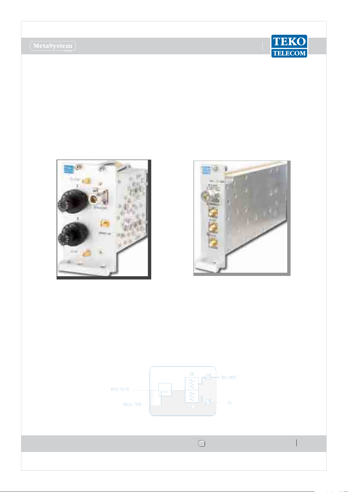
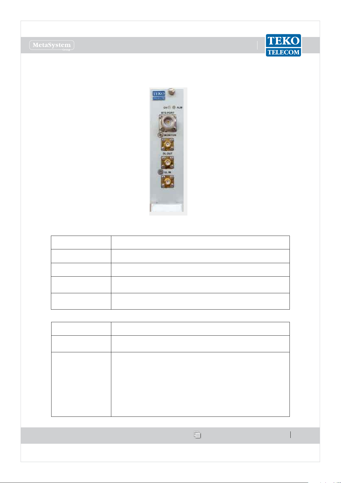
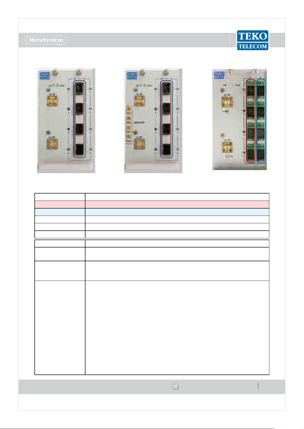
Passive Point Of Interface module (POI)
with rotary adjustable attenuators
Point Of Interface module (TAPOI) with
remote-controlled variable attenuators
Each Point of Interface module includes the duplexer, to separate/combine Downlink and
Uplink paths and two variable attenuators to make both Downlink and Uplink RF levels
separately adjustable.
A monitor port is available either for measurements or for external wireless modem
coupling.
Point Of Interface module block diagram
UL
DLDLDLDLDL
ULULULULUL
DLDLDLDLDL
OUTOUTOUTOUTOUT
BTBTBTBTBT
S PORTS PORTS PORTS PORTS PORT
MONITMONITMONITMONITMONIT
OROROROROR

www.tekotelecom.it
www.tekotelecom.it
SIRIUS: Teko Telecom Modular Coverage and Capacity System
Let us repeat !
Doc ID Number 91 080 0781 - Rel. 04 page 14
english
Point of Interface modules with separate Downlink and Uplink ports (without built-in duplexer)
are available as option.
Teko Telecom Point of Interface modules can be equipped either with manually adjustable
attenuators (POI-x models) or with remote-controlled attenuators (TAPOI-x models).
POI modules
POI modules include two rotary adjustable attenuators to make Downlink and Uplink RF
levels manually adjustable within a range of either 30dB, with 1dB step, or 10dB, with 1dB
step (POI-A10 models).
TAPOI modules
TAPOI modules include two automated variable attenuators to adjust Downlink and Uplink
RF levels via the Coverage System Supervision Module (TSPV) and Management Tools (OMT
webpages, OMC software).
www.tekotelecom.it
www.tekotelecom.it
SIRIUS: Teko Telecom Modular Coverage and Capacity System
Let us repeat !
Doc ID Number 91 080 0781 - Rel. 04 page 15
english
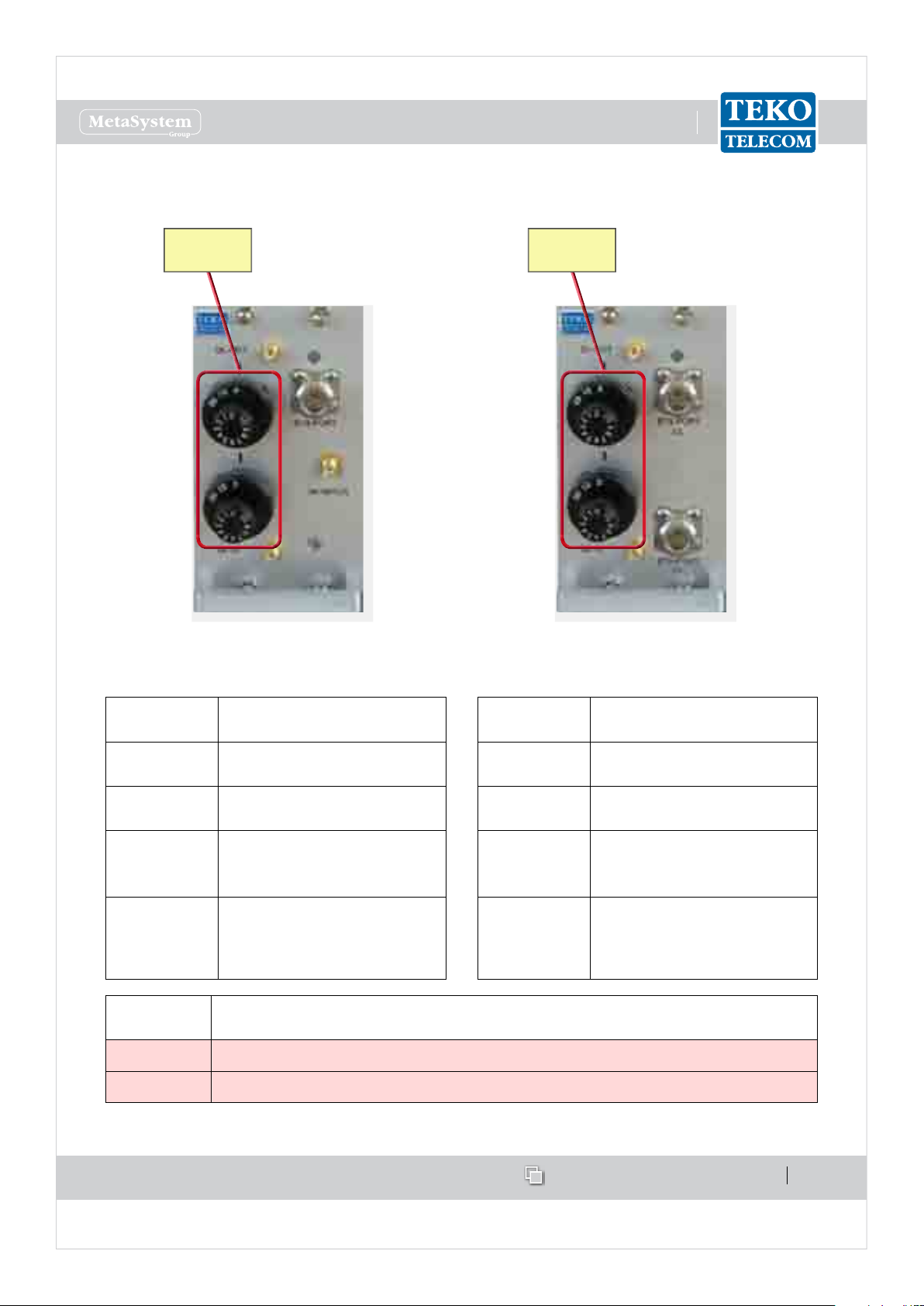
POI Modules Access Points•
Passive POI with built-in duplexer Passive POI without built-in duplexer
Adjustable
attenuators
Adjustable
attenuators
Label
(Connectors)
Description
DL-OUT
Downlink path RF output
(SMA connector)
UL-IN
Uplink path RF input (SMA
connector)
BTS PORT
RF connector (N type )
towards the signal source
(BTS, Node B or repeater)
MONITOR
Monitor port for
measurements or for external
wireless modem coupling
Label
(Connectors)
Description
DL-OUT
Downlink path RF output
SMA connector
UL-IN
Uplink path RF input SMA
connector
BTS PORT DL
Input RF connector from the
signal source - BTS, Node B
or repeater (N type)
BTS PORT UL
Output RF connector to the
signal source - BTS, Node B
or repeater (N type)
Adjustable
attenuators
Description
DL OUT Downlink path RF level adjustable attenuator (0÷30dB or 0÷10dB - 1 dB step)
UL IN Uplink path RF level adjustable attenuator (0÷30dB or 0÷10dB - 1 dB step)
www.tekotelecom.it
www.tekotelecom.it
SIRIUS: Teko Telecom Modular Coverage and Capacity System
Let us repeat !
Doc ID Number 91 080 0781 - Rel. 04 page 16
english
TAPOI Module Access Points•
TAPOI with built-in duplexer
Label (Connectors) Description
DL OUT Downlink path RF output (SMA connector)
UL IN Uplink path RF input (SMA connector)
BTS PORT RF connector (N type ) towards the signal source (BTS, Node B
or repeater)
MONITOR Monitor port for measurements or for external wireless
modem coupling
Label (LEDs) Description
ON TAPOI Module operating status green LED
ON when power supply is present
ALM TAPOI Module alarm status LED:
OFF: regular operation
Blinking Orange: presence of active alarms with warning
severity level (4)
Orange: presence of active alarms with minor severity level (3)
Blinking Red: presence of active alarms with major severity
level (2)
Red: presence of active alarms with critical severity level (1)

www.tekotelecom.it
www.tekotelecom.it
Let us repeat !
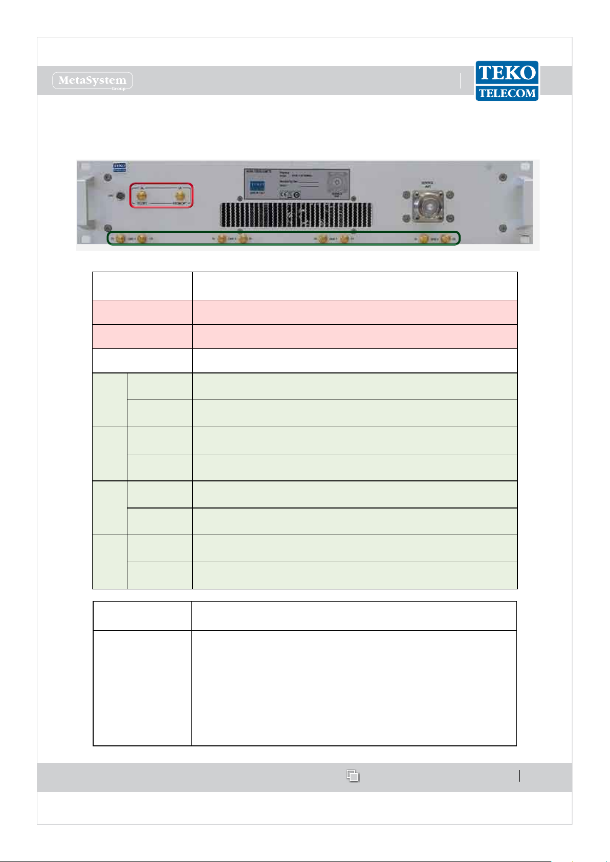
Teko Telecom Digital Donor Front End•
TheDigital Donor Front EndModule is the single-band/single-operatorSystem RF interface
towardsaDonorAntenna.NophysicalconnectionsarerequiredbetweentheDFEandthecellular
network:theDonorAntennaprovidestheconnectiontoaBTSorNodeBoveranairlink.
CoverageSystemscanbeequippedwithoneor moreDonor FrontEndmodulestomake
multiple congurations available: single operator (single band / multi-band) and multi-
operator(single-band/multi-band).
TEKO
TELECOM
CODE
TDFE-7SL 698÷716MHz 728÷746 MHz
TDFE-7SH 776÷787MHz 746÷757 MHz
TDFE-8S806 ÷824 MHz 851÷869 MHz
TDFE-8A824 ÷849 MHz 869÷894 MHz
TDFE-9S896 ÷902 MHz 935÷941 MHz
TDFE-191850 ÷1915 MHz1930 ÷1995 MHz
TDFE-AW1710 ÷1755 MHz2110 ÷2155 MHz
UPLINK
OPERATING
FREQUENCY BAND
DOWNLlNK
OPERA TING
FREQUENCY BAND
Modulation
LTE (QAM, QPSK)
LTE (QAM, QPSK)
iDEN
GSM-EDGE-TDMA-
CDMA-WCDMA-LTE
(QAM, QPSK)
iDEN
GSM-EDGE-TDMA-
CDMA-WCDMA-LTE
(QAM, QPSK)
CDMA-WCDMA-LTE
(QAM, QPSK)
DigitalDonorFrontEndModuleoperatingfrequencybandssummarytable
Asingle-bandsingle-operator modular O-air Repeatercanbesetupcombininga Digital
DonorFrontEndModuleandaServiceFrontEnd(TekoTelecomsingle-band/multi-operator
interfacetowardsaServiceAntenna).Upto4DonorFrontEndModulescanbeconnectedto
asingleServiceFrontEndtoprovideasingle-band4-operatormodularO-airRepeater.
DigitalDonorFrontEndModulescanalsobeusedtodriveOpticalSystems:theDigitalDonor
FrontEndModuleallowsOpticalSystemstobedrivenwithouttheneedofadedicatedBTSor
NodeB.Adonorantennapicks-upthesignalandtheOpticalSystemactsasarepeaterwith
SIRIUS: Teko Telecom Modular Coverage and Capacity System
distributedServiceantennasconnectedtotheRemoteUnits.ServiceFrontEndsubrackscan
Doc ID Number 91 080 0781 - Rel. 04 page 17
english
www.tekotelecom.it
www.tekotelecom.it
Let us repeat !
beconnectedtoDFEmodulestoprovidecoveragetotheareanexttotheMasterUnitsite.
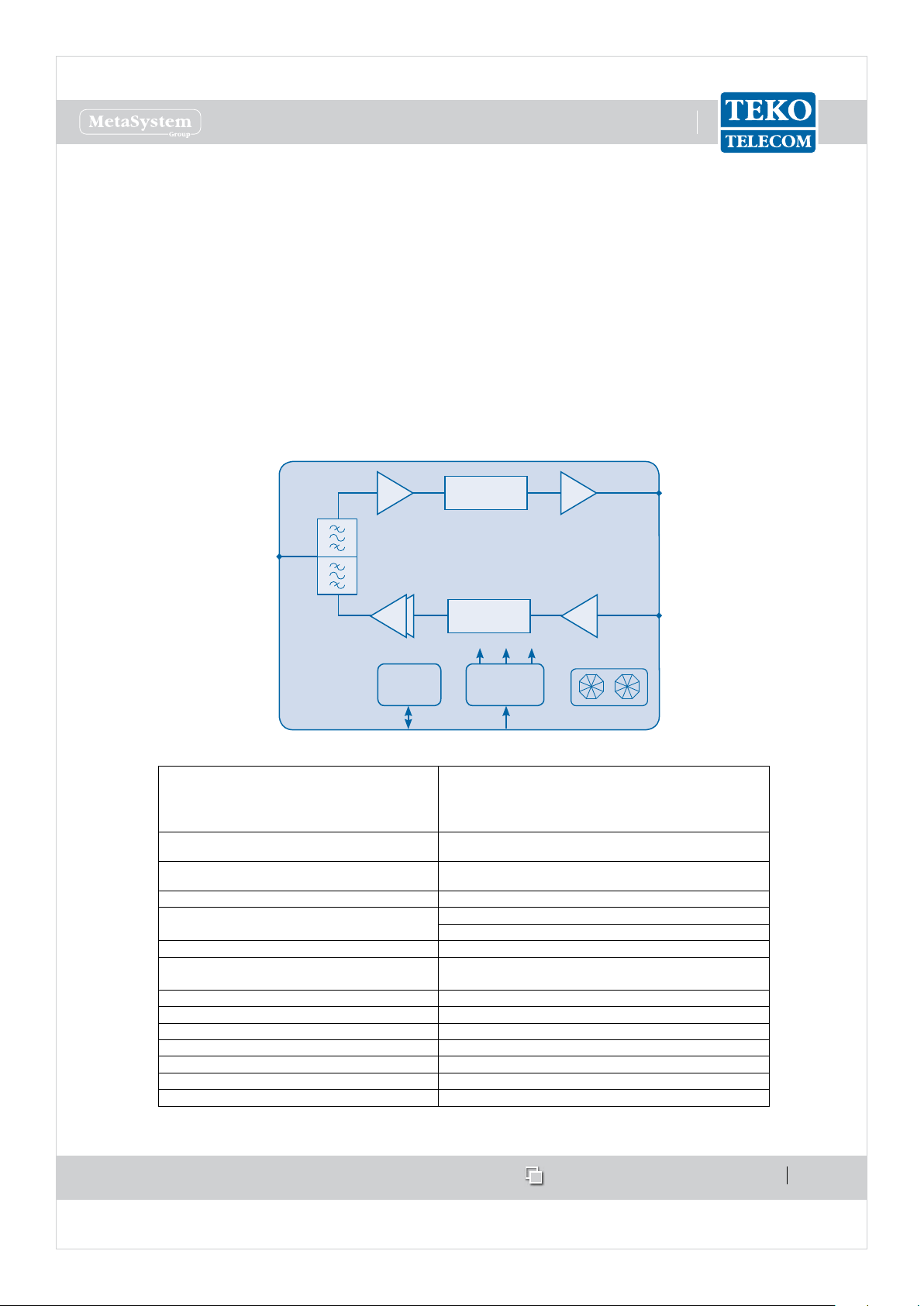
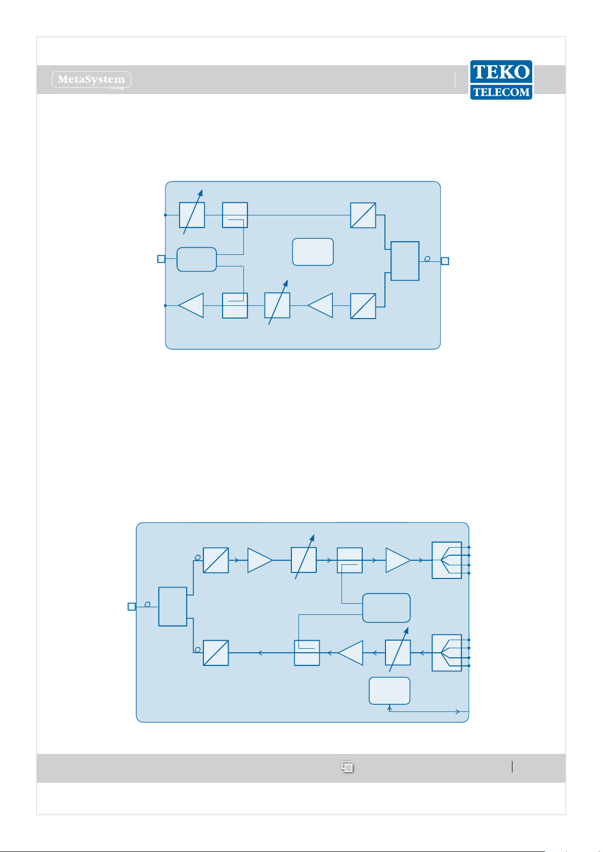
EachDFEmodulehoststheduplexer,tobeconnectedtothe Donor Antennatoseparate/
combinedownlinkanduplinkpaths.
IndownlinkthesignalfromtheDonorAntennaispreampliedbyaLowNoiseAmplierand
convertedintoanIFsignalbyadownconverter.Theselectionofthebandof frequenciesor
channelstobeextendedishandledbyadigitallter.Thedigitalltercanmanage1variable
bandor2variablesub-bands.AnupconverterconvertstheIFsignalintotheRFoutputsignal.
InuplinkthesignalfromtheServiceFrontEndSubrackorfromtheOpticalSystemisconverted
intoanIFsignalbyadownconverter,lteredandre-convertedintoanRFsignal,ampliedby
apoweramplierandre-transmittedtothesignalsource.
Donor
Antenna
Port
LNA
Duplexer
PA
μP DC/DC
RS485
DigitalFilter
DigitalFilter
+12V +1.8V+3.3V
FANS
28÷30VDC
DigitalDonorFrontEndModuleblockdiagram
COMMERCIAL CODES TDFE-7SL; TDFE-7SH
(TDFE- Teko Telecom band code)TDFE-8S; TDFE-8A; TDFE-9S
For UL/DL Operating bands please refer to TDFE-19; TDFE-AW
the Operating frequency bands Summary Table
Down-Link
Up-Link
Number of variable sub-bandsUp to 2
Variable sub-band bandwidth 200kHz to 25MHz (100kHz step) -1 sub-band
Processed Band up to 35MHz
Attenuation range on each sub-band
(relative to set RF gain)
Connector to the Donor Antenna N (f)
CoolingActive (with fans)
Power supply28÷30 Vdc
Power Consurnption 37 W
Operatingtemperature range -5°C up to +55°C (+23°F up lo + 131°F)
Weight ~ 3,5 Kg (7.7Ib)
Dimensions 3HE / 21TE
Output Power: 10 dBm
Gain: 63 dBm
Output Power: 26 dBm
Gain: 64 dBm
200kHz to 14.2MHz (100kHz step) -2 sub-bands
0÷30dB (0.5dB step) independent on each su b-band
DigitalDonorFrontEndModulestechnicalspecications
DLRF
Out
ULRF
In
SIRIUS: Teko Telecom Modular Coverage and Capacity System
Doc ID Number 91 080 0781 - Rel. 04 page 18
english
www.tekotelecom.it
www.tekotelecom.it
SIRIUS: Teko Telecom Modular Coverage and Capacity System
Let us repeat !
Doc ID Number 91 080 0781 - Rel. 04 page 19
english
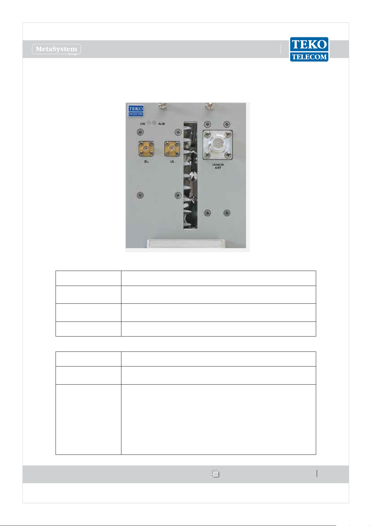
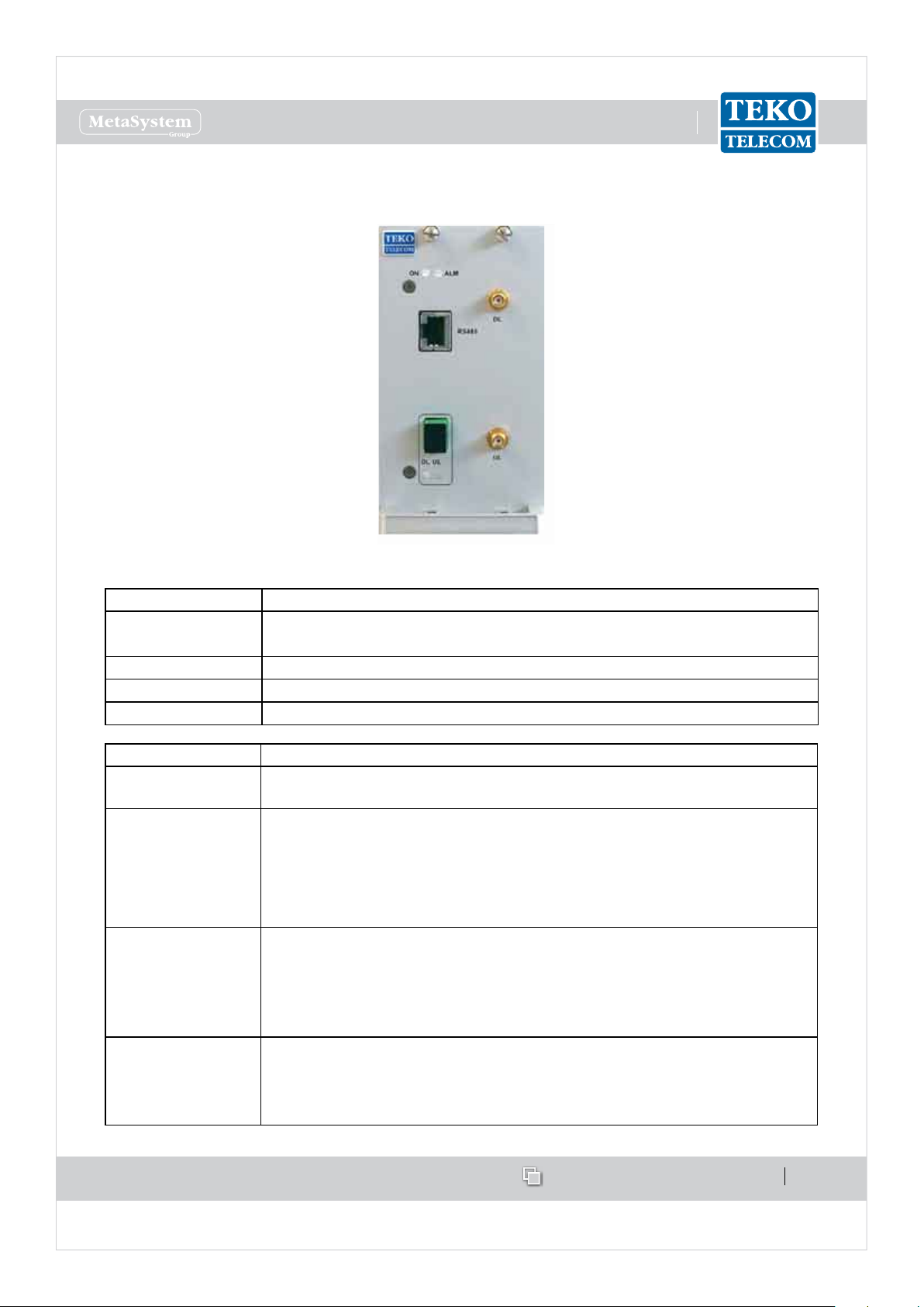
Digital Donor Front End Module Access Points
Label (Connectors) Description
DL Downlink path RF output (SMA connector) to Service Front
End or Fiber Optic Modules
UL Uplink path RF input (SMA connector) from Service Front End
or Fiber Optic Modules
DONOR ANT Donor Antenna Port (N type connector)
Label (LEDs) Description
ON
Digital Donor Front End Module operating status green LED:
ON when power supply is present
ALM
Digital Donor Front End Module alarm status LED:
OFF: regular operation
Blinking Orange: presence of active alarms with warning
severity level (4)
Orange: presence of active alarms with minor severity level (3)
Blinking Red: presence of active alarms with major severity
level (2)
Red: presence of active alarms with critical severity level (1)
www.tekotelecom.it
www.tekotelecom.it
SIRIUS: Teko Telecom Modular Coverage and Capacity System
Let us repeat !
Doc ID Number 91 080 0781 - Rel. 04 page 20
english
Equipment extending coverage / distributing capacity1.1.2
Teko Telecom Service Front End•
Teko Telecom Service Front End Subrack is a single-band/multi operator equipment, driven
by Digital Donor Front End Modules and connected to a Service Antenna to provide wireless
signal to the area to be covered. The equipment is available in four dierent power classes:
Very High, High, Medium and Low.
A single-band single-operator modular O-air Repeater can be set-up combining a Digital
Donor Front End Module and a Service Front End. Up to 4 Donor Front End Modules can
be connected to a single Service Front End subrack to provide a single-band 4-operator
Repeater.
The Service Front End subrack can also be used in Optical Systems to provide coverage to the
area adjoining the Master Unit site.
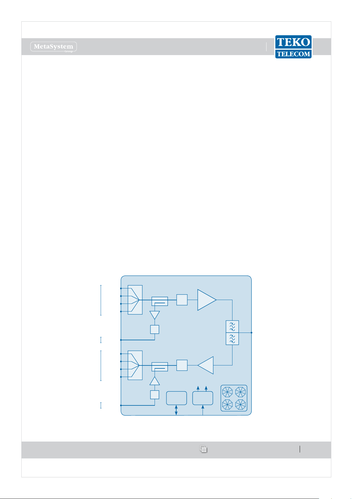
The SFE 19”/2U subrack hosts the duplexer, to be connected to the Service Antenna to
separate/combine Downlink and Uplink paths.
In Downlink the signals from the Donor Front-End Modules are combined and amplied by a
Power Amplier.
In Uplink, the RF signal from the Service antenna is amplied by a Low Noise Amplier (LNA)
and split to feed up to 4 Donor Front-End Modules.
Auxiliary ports are available to drive an Optical System.
PA
DL in1
Service
Antenna
Port
Duplexer
P DC/DC
+3.3V +5V
28÷30VDCRS485
Digital
Attenuator
DL in2
DL in3
DL in4
DL out
LNA
UL out1
Digital
Attenuator
UL out2
UL out3
UL out4
UL in
Digital
Attenuator
Digital
Attenuator
4:1
4:1
FANS
From DFEs
To DFEs
To Optics
From Optics
Service Front End block diagram
www.tekotelecom.it
www.tekotelecom.it
SIRIUS: Teko Telecom Modular Coverage and Capacity System
Let us repeat !
Doc ID Number 91 080 0781 - Rel. 04 page 21
english
Service Front End Access Points
Label
(Connectors)
Description
DL TO OPT Downlink path RF output (SMA connector) - to Optics
UL FROM OPT Uplink path RF input (SMA connector) - from Optics
SERVICE ANT Service Antenna Port (N type )
DFE1
DL
Downlink path RF input (SMA connector) - from Digital Donor
Front End 1
UL
Uplink path RF output (SMA connector) - to Digital Donor Front
End 1
DFE2
DL
Downlink path RF input (SMA connector) - from Digital Donor
Front End 2
UL
Uplink path RF output (SMA connector) - to Digital Donor Front
End 2
DFE3
DL
Downlink path RF input (SMA connector) - from Digital Donor
Front End 3
UL
Uplink path RF output (SMA connector) - to Digital Donor Front
End 3
DFE4
DL
Downlink path RF input (SMA connector) - from Digital Donor
Front End 4
UL
Uplink path RF output (SMA connector) - to Digital Donor Front
End 4
Label
(LEDs)
Description
LED
Service Front End subrack general operating status LED
Green: no alarm
Blinking Orange: presence of active alarms with warning
severity level (4)
Orange: presence of active alarms with minor severity level (3)
Blinking Red: presence of active alarms with major severity
level (2)
Red: presence of active alarms with critical severity level (1)
www.tekotelecom.it
www.tekotelecom.it
SIRIUS: Teko Telecom Modular Coverage and Capacity System
Let us repeat !
Doc ID Number 91 080 0781 - Rel. 04 page 22
english
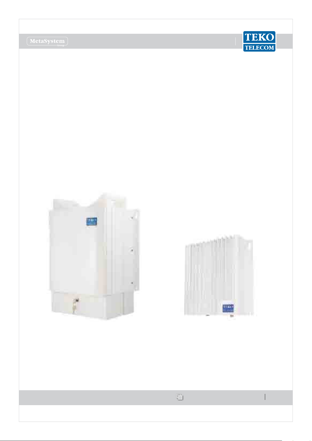
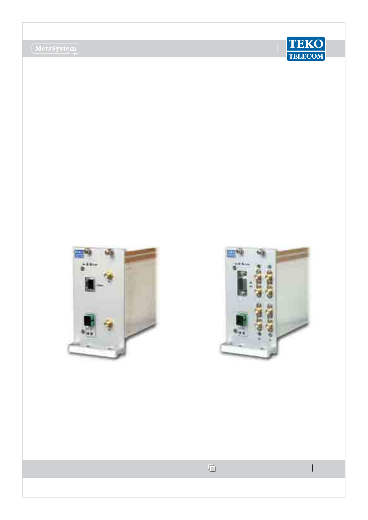
Teko Telecom Remote Units•
Remote Units are used in Optical Systems to distribute wireless signals throughout the area
to be covered. They are connected to the Fiber Optic Transmitter/Receiver Modules equipped
in the Master Unit.
Remote Units are equipped with the Fiber Optic Receiver and Transmitter module (for Optical
to RF and RF to Optical conversion), power ampliers and ltering.
They can be Single or Multi-band with four dierent RF power classes: Very High, High,
Medium and Low.
Remote Units with dierent power classes can be driven simultaneously by the same Master
Unit to distribute capacity or extend coverage into dierent locations at the same time.
Very High, High and Medium Power Remote Units are equipped in a weatherproof IP66
case. Low Power Remote Units are equipped in an IP32 case; a protection kit, providing IP66
protection degree, is available as option for installation in harsh environments.
Single, Dual or Tri-band Very High, High and
Medium Power Remote Unit
Single band / Multi-band Low Power Remote
Unit
Please refer to Paragraph 1.2.2 for a detailed description of Remote Units.
www.tekotelecom.it
www.tekotelecom.it
SIRIUS: Teko Telecom Modular Coverage and Capacity System
Let us repeat !
Doc ID Number 91 080 0781 - Rel. 04 page 23
english
Modules providing the optical interface towards Remote Units1.1.3
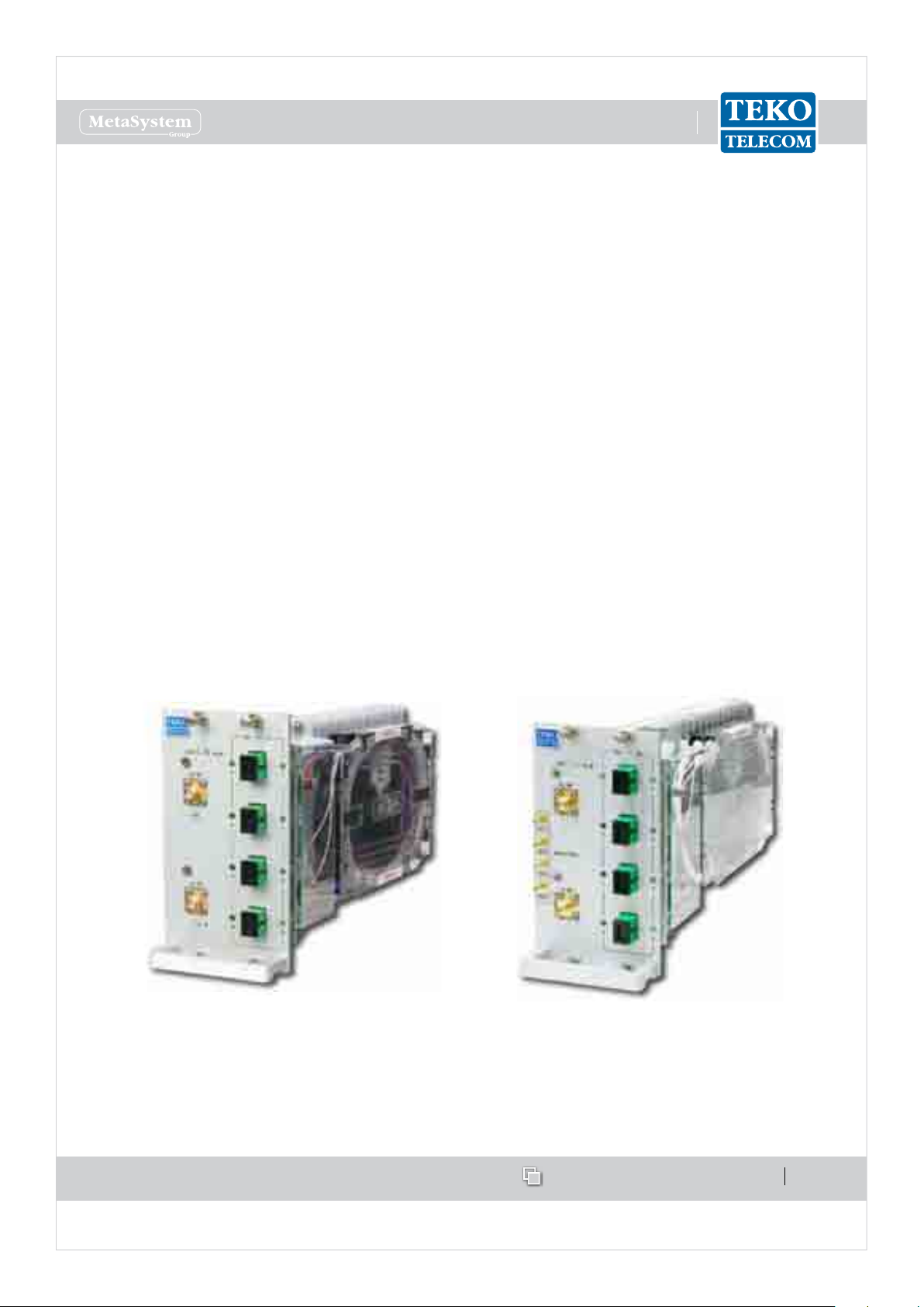
Fiber Optic Transmitter/Receiver Modules•
Fiber Optic Transmitter/Receiver Modules are the optical interface between Master Unit and
Remote Units: they provide RF-to-Optical/Optical-to-RF conversion. They are connected to
Remote Units via single mode optical bers, with Uplink and Downlink signals transmitted
over the same bre (Wavelength Division Multiplexing -WDM technology).
Dierent congurations are available: a single Fiber Optic Transmitter/Receiver Module can
be equipped with 1 Optical Transmitter and 1 Optical Receiver (10dB optical link budget, up
to 20km distance - 12.4 miles), or 1 Optical Transmitter split by 2 and 2 combined Optical
Receivers (10dB optical link budget, up to 20km distance- 12.4 miles), or 1 Optical Transmitter
split by 4 and 4 combined Optical Receivers (6dB optical link budget, up to 12km distance -
7.5 miles).
The Fiber Optic Transmitter/Receiver Module in 1:4 conguration can manage up to 4 Remote
Units.
The Fiber Optic Transmitter/Receiver Module in 1:1 conguration is able to drive up to 5
cascaded Remote Units with dierent wavelengths in Up-link.
Fiber Optic Transmitter/Receiver Module in 1:4
conguration
Fiber Optic Transmitter/Receiver Module (1:4
conguration) with monitor for E9-1-1 service
The Fiber Optic Transmitter provides the RF to optical conversion (Downlink side): the module
RF section covers the 380 to 2200MHz band (TTRC models) or the 380 to 2700MHz band
www.tekotelecom.it
www.tekotelecom.it
SIRIUS: Teko Telecom Modular Coverage and Capacity System
Let us repeat !
Doc ID Number 91 080 0781 - Rel. 04 page 24
english
(TTRU models).
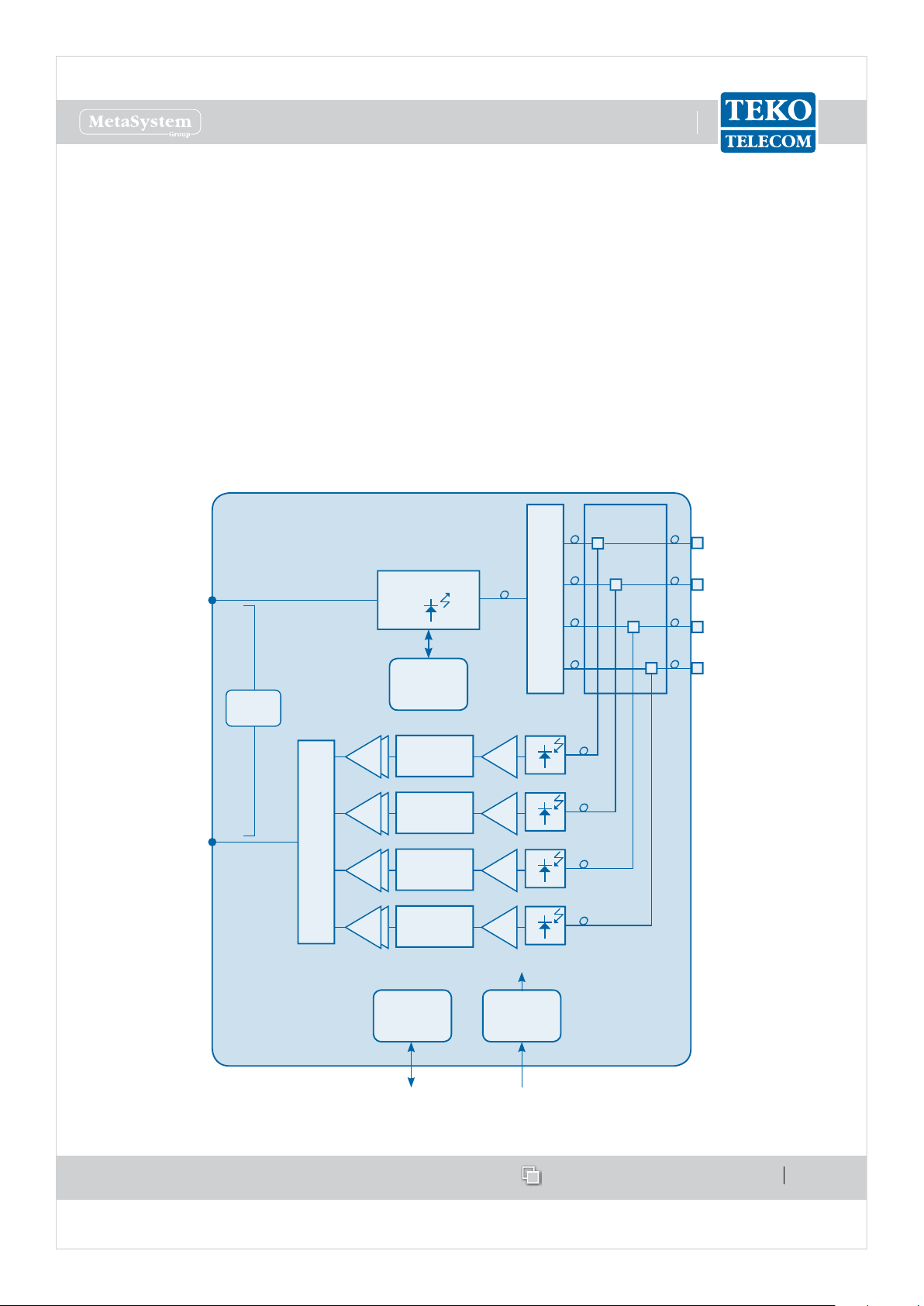
Fiber Optic Receivers convert uplink optical signals from Remote Units into RF. They operate
in the third window (Optical wavelength 1490 ÷ 1570 nm).
Each Fiber Optic module is controlled by a microprocessor which provides the following data
to the Supervision Module:
optical power received by each optical receiver, -
Downlink attenuator and Uplink attenuator attenuation setting (0 ÷ 15dB), -
received optical power alarms. -
An auto-levelling functionality (AGC) compensates up to 10dB optical link loss in order
to guarantee constant gain over dierent optical budgets. This feature simplies system
installation, makes commissioning quick and easy and avoids eld adjustments.
CONTROL
1:4
OPT
MODEM
4:1
P DC/DC
28÷30VDCRS485
PA
DIGITAL
ATTENUATOR
LNA
PA
DIGITAL
ATTENUATOR
LNA
PA
DIGITAL
ATTENUATOR
LNA
PA
DIGITAL
ATTENUATOR
LNA
DL RF
WDM
DL/UL 1
DL/UL 3
DL/UL 2
DL/UL 4
UL RF
LASER
Block diagram: Fiber Optic Transmitter/Receiver Module equipped with 1 Optical Transmitter split by 4 and 4
combined Optical Receivers (WDM technology)
www.tekotelecom.it
www.tekotelecom.it
SIRIUS: Teko Telecom Modular Coverage and Capacity System
Let us repeat !
Doc ID Number 91 080 0781 - Rel. 04 page 25
english
Fiber Optic Transmitter/Receiver Module Access Points
Label (Connectors) Description
DL Fiber Optic Transmitters (1 to 4) optical output connectors (SC-APC)
UL Fiber Optic Receivers (1 to 4) optical input connectors (SC-APC)
DL RF Fiber Optic Transmitter RF input SMA connector
UL RF Fiber Optic Receiver RF output SMA connector
Monitor RXn Monitor ports (RX1 to RX4) for E 9-1-1 service
Label (LEDs) Description
ON
Fiber Optic Module operating status green LED
ON when power supply is present
ALM
Fiber Optic Module alarm status LED:
OFF: regular operation; BLINKING ORANGE/ORANGE: warning/minor;
BLINKING RED/RED: major/critical
DL UL
These LEDs describe the general operating status of Remote Units (1 to
4) connected to Fiber Optic Transmitters (DL) and Repeaters (UL) .
Each pair of DL/UL leds takes the same color as the general operating status
led of the Remote Unit connected to the optical connector, except when
a Laser Fault occurs in the Fiber Optic transmitter. If this fault occurs, all •
DL leds turn RED and the ALM Led switches on (RED).
a Low Optical Power alarm arises in the Fiber Optic receiver. If this alarm •
arises, the UL led turns RED and the ALM Led switches on (RED).
Each pair of DL/UL LEDs can be:
Green: Remote Unit status OK
Blinking Orange: presence of RU active alarms with warning severity level (4)
Orange: presence of RU active alarms with minor severity level (3)
Blinking Red: presence of RU active alarms with major severity level (2)
Red: presence of RU active alarms with critical severity level (1)
Fiber Optic Module 1:4
conguration
Fiber Optic Module 1:4
conguration - WDM
Fiber Optic Module 1:4
conguration - WDM with
Monitor for E9-1-1 service
www.tekotelecom.it
www.tekotelecom.it
SIRIUS: Teko Telecom Modular Coverage and Capacity System
Let us repeat !
Doc ID Number 91 080 0781 - Rel. 04 page 26
english
Master and Slave Point to Point Modules•
Master and Slave Point to Point Modules provide an optical point to point link allowing a
separation distance -up to 20km- between RF interface subracks and optical subracks.
The point to point link is suitable when the signal source (BTS, Node B, Repeater) is located
far from the area to be covered or when the same optical system provides coverage to several
separate buildings; in these applications the point to point link allows the transmission of
signals from/to a group of remote units over a single optical bre, thus providing a signicant
reduction in the number of ber optics running long distances.
The point to point link requires the RF interface subracks to be equipped with Master Point
to Point modules and the remote optical subracks to be equipped with Slave Point to Point
modules. The RF Interface subracks can be equipped with up to 4 Master Point to Point modules
for the management of up to 4 optical subracks, installed in dierent remote locations.
Master Point to Point Module Slave Point to Point Module
Each Master Point to Point Module is connected to a Slave Point to Point Module, equipped in
a remote optical subrack, via a single optical bre (single-mode SMR 9/125).
www.tekotelecom.it
www.tekotelecom.it
SIRIUS: Teko Telecom Modular Coverage and Capacity System
Let us repeat !
Doc ID Number 91 080 0781 - Rel. 04 page 27
english
Point to Point Modules (Master and Slave) perform the electrical-to-optical/optical-to-
electrical conversion required for the transmission of downlink and uplink signals over the
connecting optical bre.
1550nm
UL RF output
SMA (f)
DL RF input
SMA (f)
RS485
port
1310nm
E
O
E
O
Coupler
Coupler
Att.
Att.
DL/UL
optical SC/APC
connector
WDM
Modem
P
Master Point to Point Module block diagram
The Slave Point to Point module includes the 4-way splitter/combiner to manage up to 4 Fiber
Optic Transmitter/Receiver Modules. A built-in Supervision unit controls the remote optical
subrack, hosting the Slave Point to Point module, and all connected Remote Units.
The Coverage System Supervision Module communicates with the Slave Point to Point module
built-in Supervision unit via the single-mode optical ber connecting Master and Slave Point
to Point modules.
An RS232 port on the Slave Point to Point Module front panel allows local communication
with the built-in supervision.
1310nm
DL RF outputs
SMA (f)
connectors
UL RF inputs
SMA (f)
connectors
RS232
1550nm
O
E
O
E
Coupler
Att.
WDM
Modem
P
DL/UL
optical SC/APC
connector
Att.
Slave Point to Point Module block diagram
www.tekotelecom.it
www.tekotelecom.it
SIRIUS: Teko Telecom Modular Coverage and Capacity System
Let us repeat !
Doc ID Number 91 080 0781 - Rel. 04 page 28
english
Master Point to Point Module Access Points
Master Point to Point Module
Label (Connectors) Description
DL UL Optical power input/output SC-APC connector (from/to Slave Point to
Point Module)
RS485 RJ45 connector for RS485 connection to the Supervision Module
DL RF input SMA connector (from the System RF Interface modules)
UL RF output SMA connector (to the System RF Interface modules)
Label (LEDs) Description
ON
Master Point to Point Module operating status green LED:
ON when power supply is present
ALM Point to Point Module alarm status LED:
OFF: regular operation
Blinking Orange: presence of active alarms with warning severity level (4)
Orange: presence of active alarms with minor severity level (3)
Blinking Red: presence of active alarms with major severity level (2)
Red: presence of active alarms with critical severity level (1)
DL Fiber Optic Transmitter operating status LED:
BLINKING GREEN: the module is reaching its operating temperature
GREEN optical output power is available
ORANGE: warning: optical output power is degradated
RED: Laser Fault: no optical output power
UL
Fiber Optic Receiver operating status LED:
GREEN: +6dBm to -4dBm optical input power
YELLOW: -4dBm to -5dBm optical input power
RED: optical input power is >+6dBm or <-5dBm
 Loading...