

Page 1
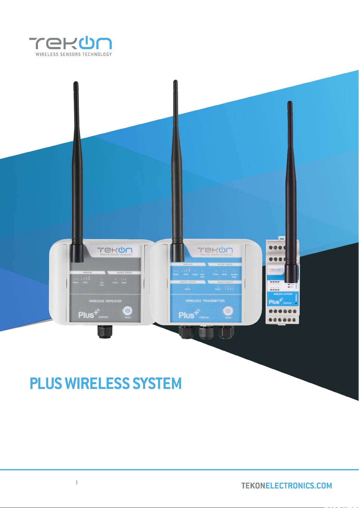
PLUS WIRELESS SYSTEM
INSTALLATION GUIDE
TEKON ELECTRONICS AVEIRO, PORTUGAL
TEKON ELECTRONICS AVEIRO, PORTUGAL
P.: +351 234 303 320 M.: +351 933 033 250 E.: sales@tekonelectronics.com
P.: +351 234 303 320 M.: +351 933 033 250 E.: [email protected]
IG.PLUS.ENG.V01.1.2018
Page 2

PLUS WIRELESS SYSTEM
INSTALLATION GUIDE
Table of contents
DUOS WIRELESS SYSTEM INSTALLATION GUIDE
step
01
step
02
step
03
WGW420 PLUS WIRELESS GATEWAY CONFIGURATION
Pages 4 to 12
TWP4AI PLUS WIRELESS TRANSMITTER CONFIGURATION
Pages 13 to 19
TWP4AI TRANSMITTER ANALOG INPUT CONFIGURATION
Pages 20 to 23
step
04
2
TWP4AI TRANSMITTER DIGITAL INPUT CONFIGURATION
Pages 24 to 26
Page 3

PLUS WIRELESS SYSTEM
INSTALLATION GUIDE
Table of contents
DUOS WIRELESS SYSTEM INSTALLATION GUIDE
step
05
step
06
TWP4AI TRANSMITTER DIGITAL OUTPUTS CONFIGURATION
Pages 27 to 32
5.1 LINK LOST OUTPUT
Page 28
5.2 REMOTE CONTROL OUTPUT
Page 30
5.3 EXTERNAL POWER CONTROL OUTPUT
Page 31
WGW420 GATEWAY ANALOG OUTPUTS CONFIGURATION
Pages 33 to 35
step
07
step
08
3
WRP001 PLUS WIRELESS REPEATER CONFIGURATION
Pages 36 to 41
SITE SURVEY MODE
Pages 42 and 43
Page 4

step
01
WGW420 PLUS WIRELESS GATEWAY CONFIGURATION
Page 5
step
PLUS WIRELESS SYSTEM INSTALLATION GUIDE
01
01
02
WGW420 PLUS WIRELESS GATEWAY CONFIGURATION
TEKON CONFIGURATOR SOFTWARE is only compatible with the Microsoft® Windows® Operating System.
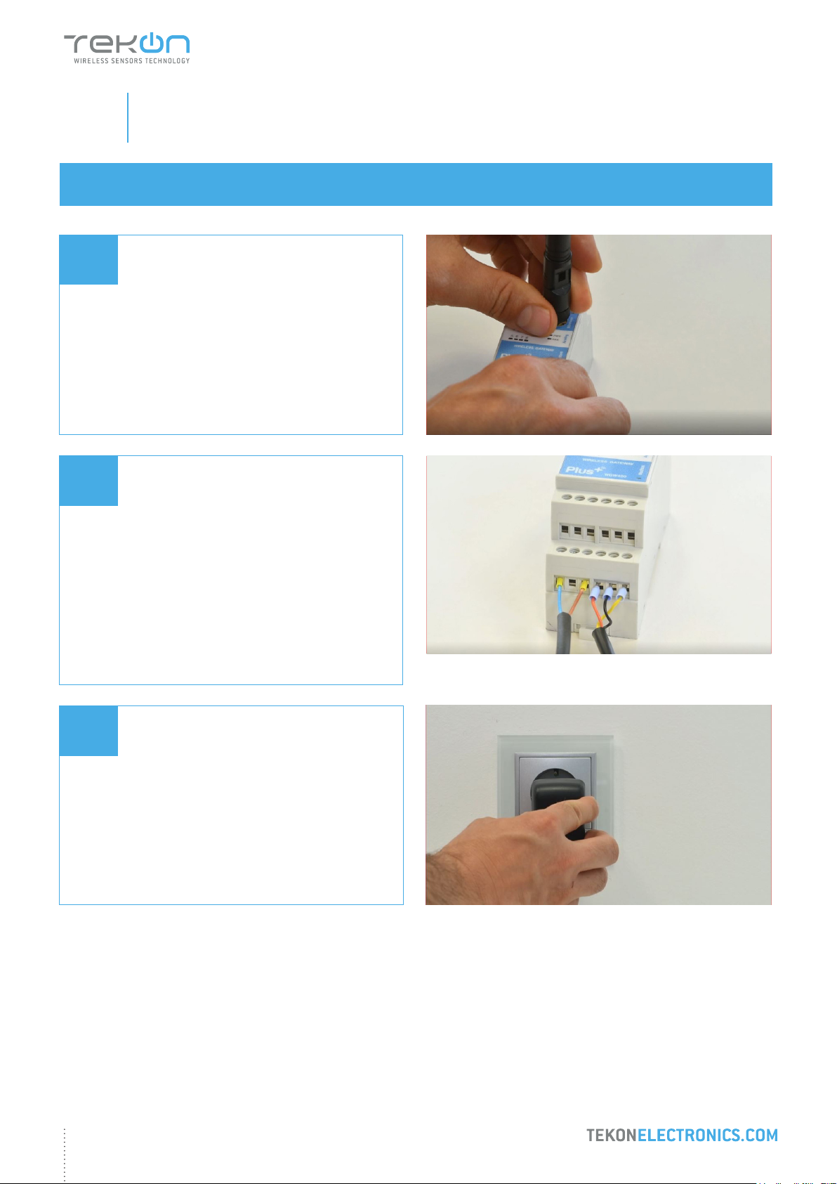
Connect the antenna to the Gateway.
Wiring
Connect the power supply and then the
RS485-USB cable to the Gateway.
Wire Indication:
Blue - GND; Brown - +24 VDC; Orange - Data+ (A); Black - GND; Yellow - Data - (B)
03
Power ON the device.
5
Page 6
step
PLUS WIRELESS SYSTEM INSTALLATION GUIDE
01
04
WGW420 PLUS WIRELESS GATEWAY CONFIGURATION
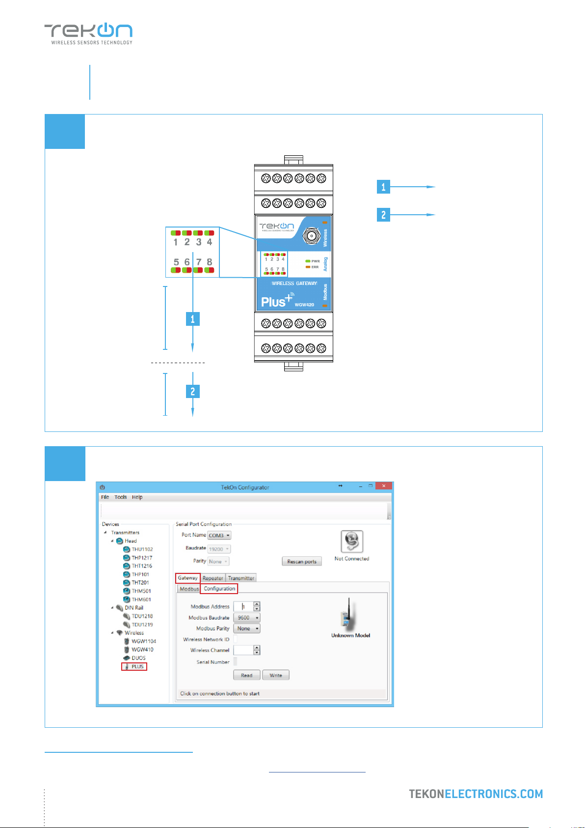
Check device connection state by LED indication.
Green LEDs
permanently on
Red LEDs
permanently on
WIRELESS GATEWAY
10 Seconds to enter
conguration mode
05
Normal mode
Open Tekon Congurator Software1 and select PLUS >> Gateway >> Conguration
2
3
1
1
Tekon Congurator software is free of charge and available at www.tekonelectronics.com
6
Page 7
step
PLUS WIRELESS SYSTEM INSTALLATION GUIDE
01
06
WGW420 PLUS WIRELESS GATEWAY CONFIGURATION
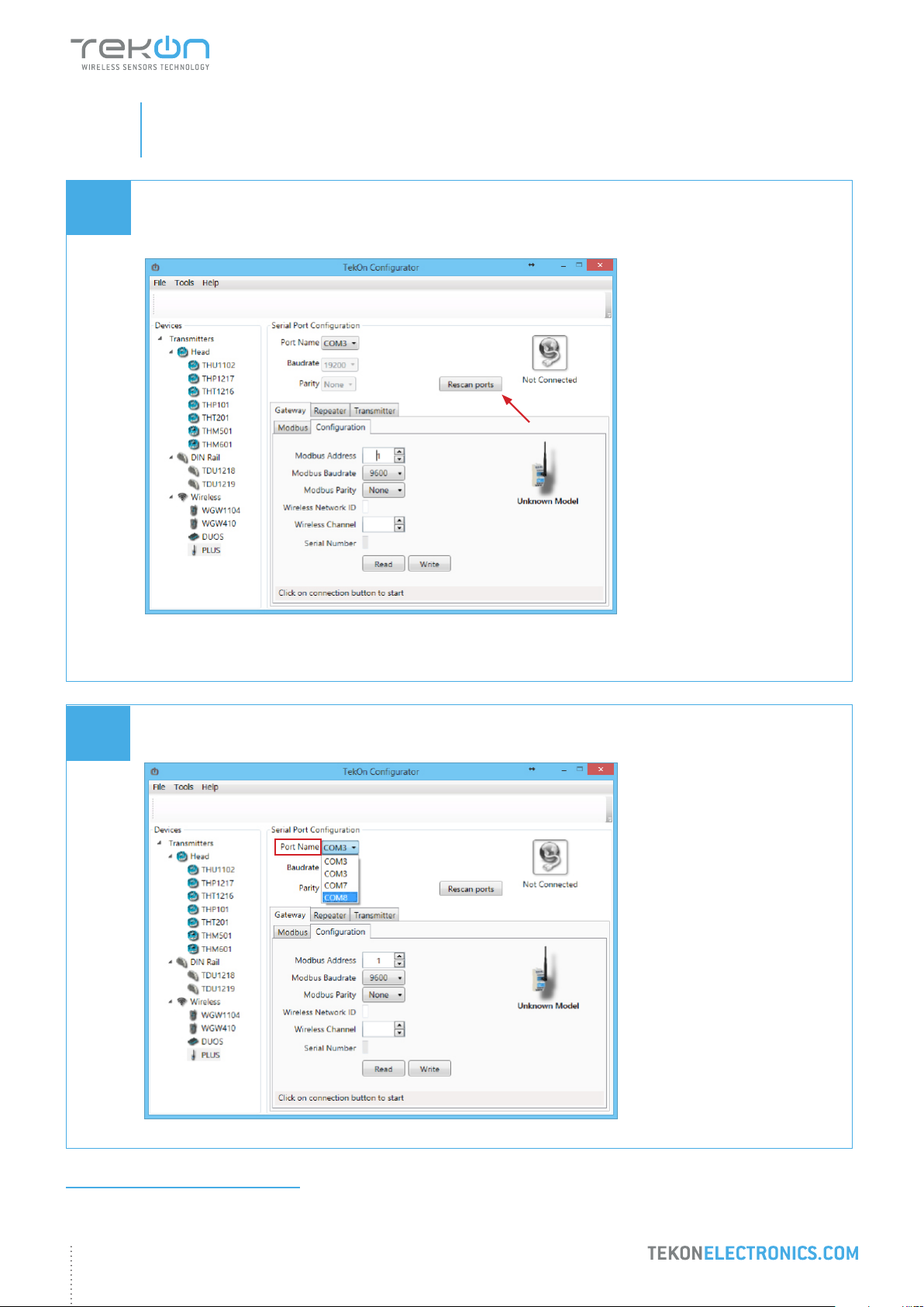
Select serial port corresponding to WGW420 PLUS Wireless Gateway
Click on the Rescan Ports button.
07
Select corresponding Port name2.
2
You can check device’s serial port name in “Device Manager” on Microsoft ® Windows® operating system.
7
Page 8
step
PLUS WIRELESS SYSTEM INSTALLATION GUIDE
01
08
WGW420 PLUS WIRELESS GATEWAY CONFIGURATION
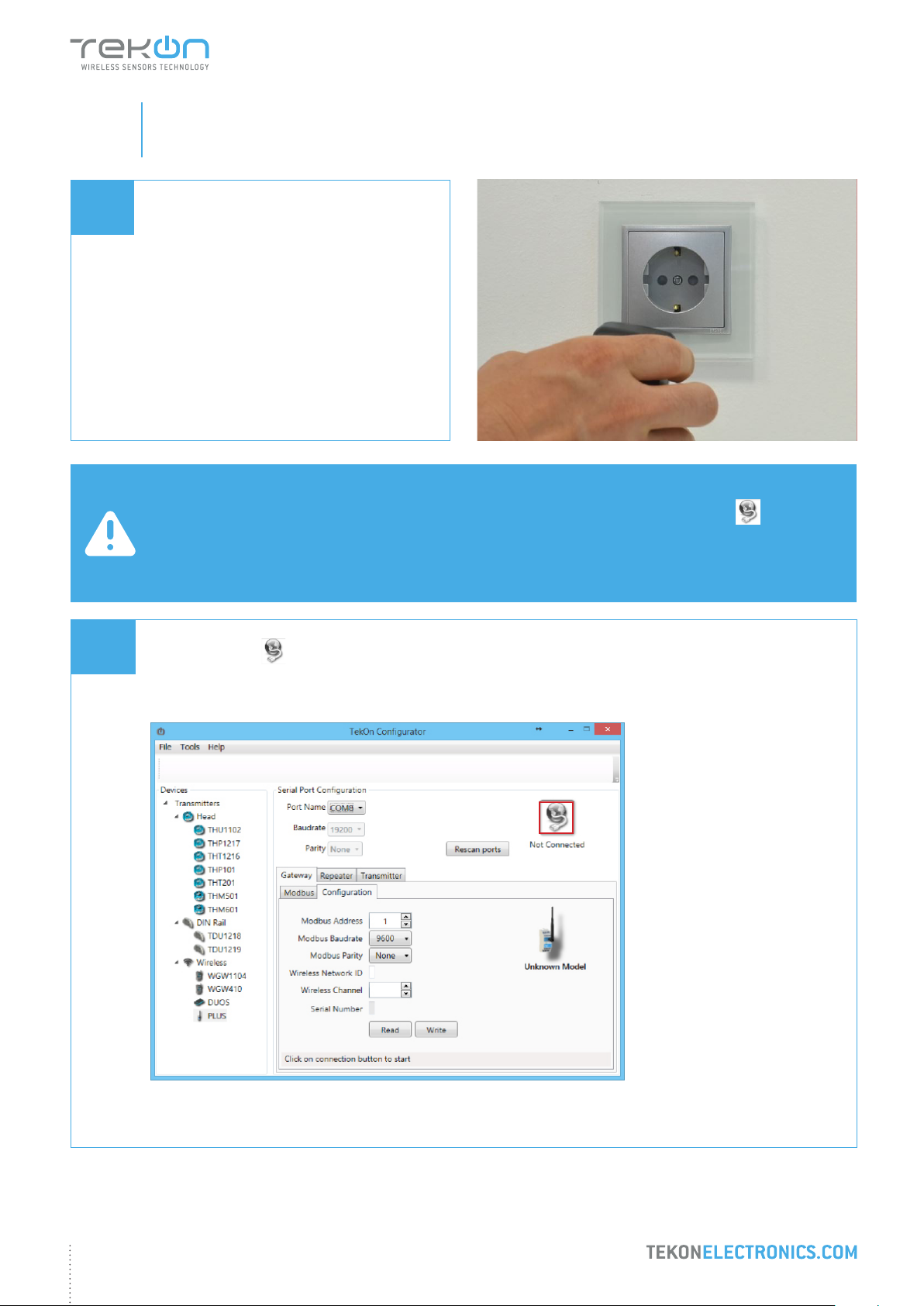
Perform a power cycle on the Gateway.
NOTE:
After power up, you have 10 seconds to enter conguration mode by clicking on Connect button ( )
(while green LEDs are permanently on).
In this mode, you can manage device parameters: Modbus Address, Modbus Baudrate, Modbus Parity, Wireless
Network ID and Wireless Channel.
09
Click on Connect ( ) button to enter conguration mode.
8
Page 9

step
PLUS WIRELESS SYSTEM INSTALLATION GUIDE
01
09
WGW420 PLUS WIRELESS GATEWAY CONFIGURATION
The status string at the bottom of the software window provides feedback on ongoing operations.
You can also verify conguration mode activation by checking LEDs on the gateway.
Conguration mode
NOTE:
When the 10-second time frame to enter conguration mode is exceeded, the LEDs will turn permanently red and
the gateway will enter normal operation mode.
To re-enter conguration mode, a power reset must be performed - step 8.
Green LEDs performing
scan animation
WIRELESS GATEWAY
9
Page 10
step
PLUS WIRELESS SYSTEM INSTALLATION GUIDE
01
10
WGW420 PLUS WIRELESS GATEWAY CONFIGURATION
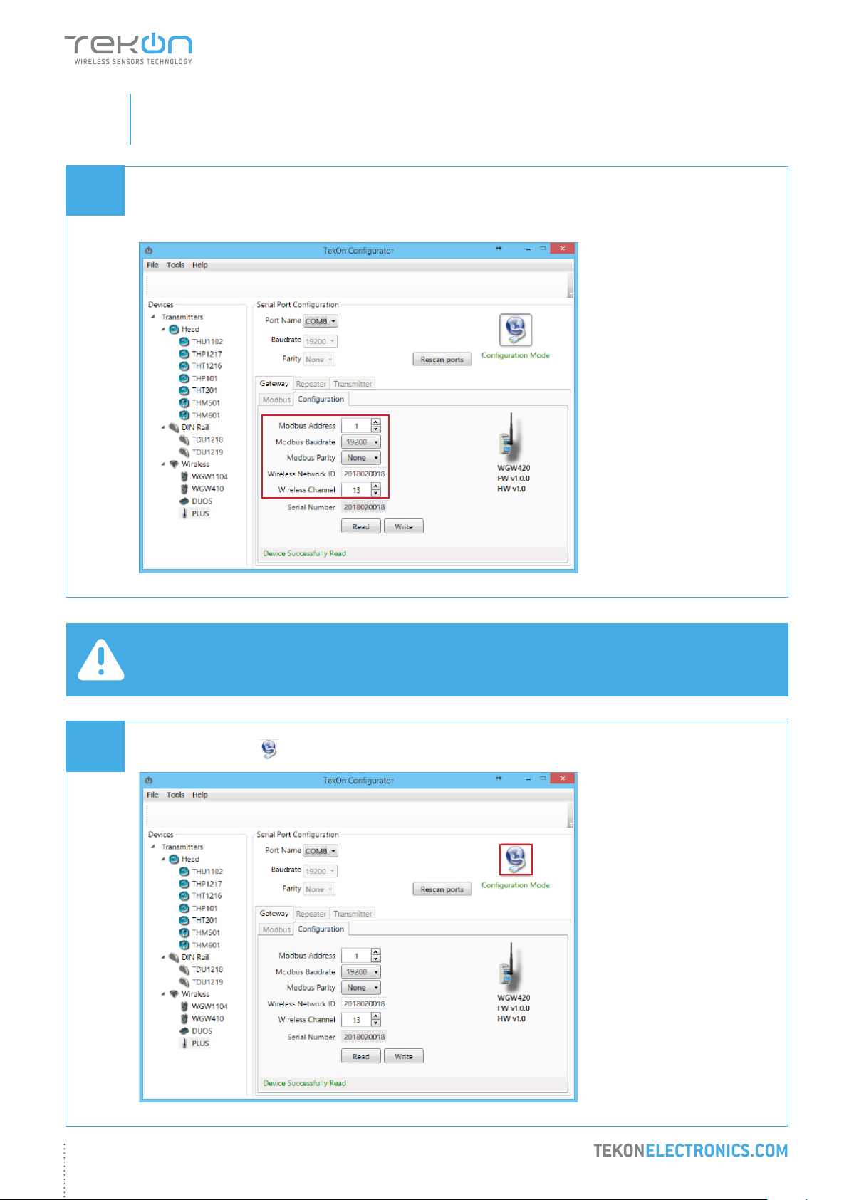
Take note of device conguration data available, namely: Modbus Address, Modbus Baudrate, Modbus Parity,
Wireless Network ID and Wireless Channel.
11
NOTE:
The wireless network connection between devices is ensured by setting the same Wireless Network ID and
Wireless Channel parameters.
Click on Disconnect ( ) button.
10
Page 11
step
PLUS WIRELESS SYSTEM INSTALLATION GUIDE
01
12
WGW420 PLUS WIRELESS GATEWAY CONFIGURATION
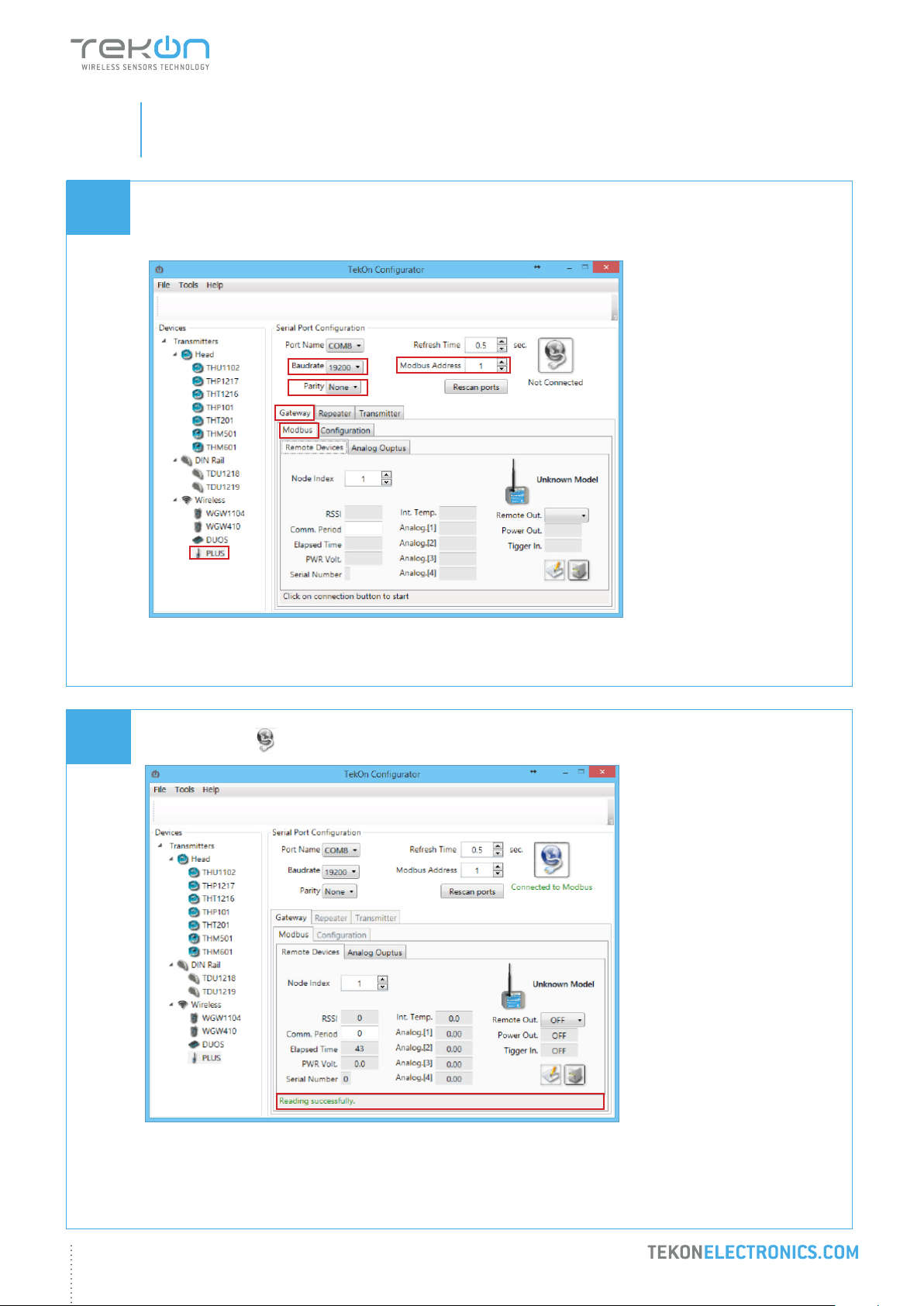
Modbus Communication
Select Modbus tab of the Gateway and set the previously saved congurations.
13
Ensure that Port name, Baudrate, Parity and Modbus Address elds are the same as those obtained in
conguration mode.
Click on Connect ( ) button and check operation status at the bottom of the window.
11
The messages Connected to Modbus and Reading successfully will appear if Serial Port conguration parameters
are correct and the Modbus connection is established.
Page 12
step
PLUS WIRELESS SYSTEM INSTALLATION GUIDE
01
WGW420 PLUS WIRELESS GATEWAY CONFIGURATION
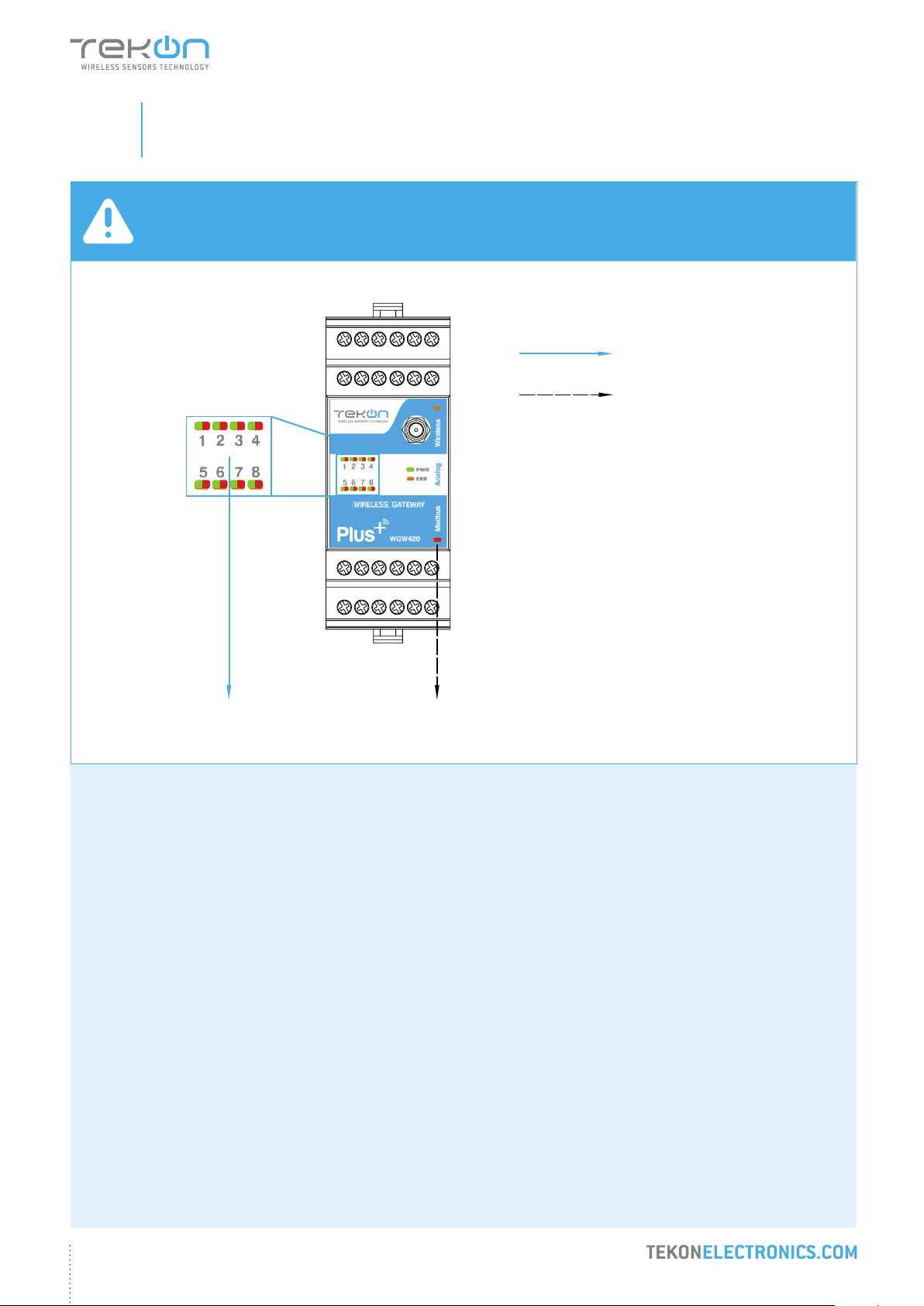
NOTE:
See WGW420 Datasheet to access LED indication information - page 4.
Red LEDs permanently on
LED ashes on each wireless
communication
WIRELESS GATEWAY
12
Page 13

step
02
TWP4AI PLUS WIRELESS TRANSMITTER CONFIGURATION
Page 14
step
PLUS WIRELESS SYSTEM INSTALLATION GUIDE
02
01
02
TWP4AI PLUS WIRELESS TRANSMITTER CONFIGURATION
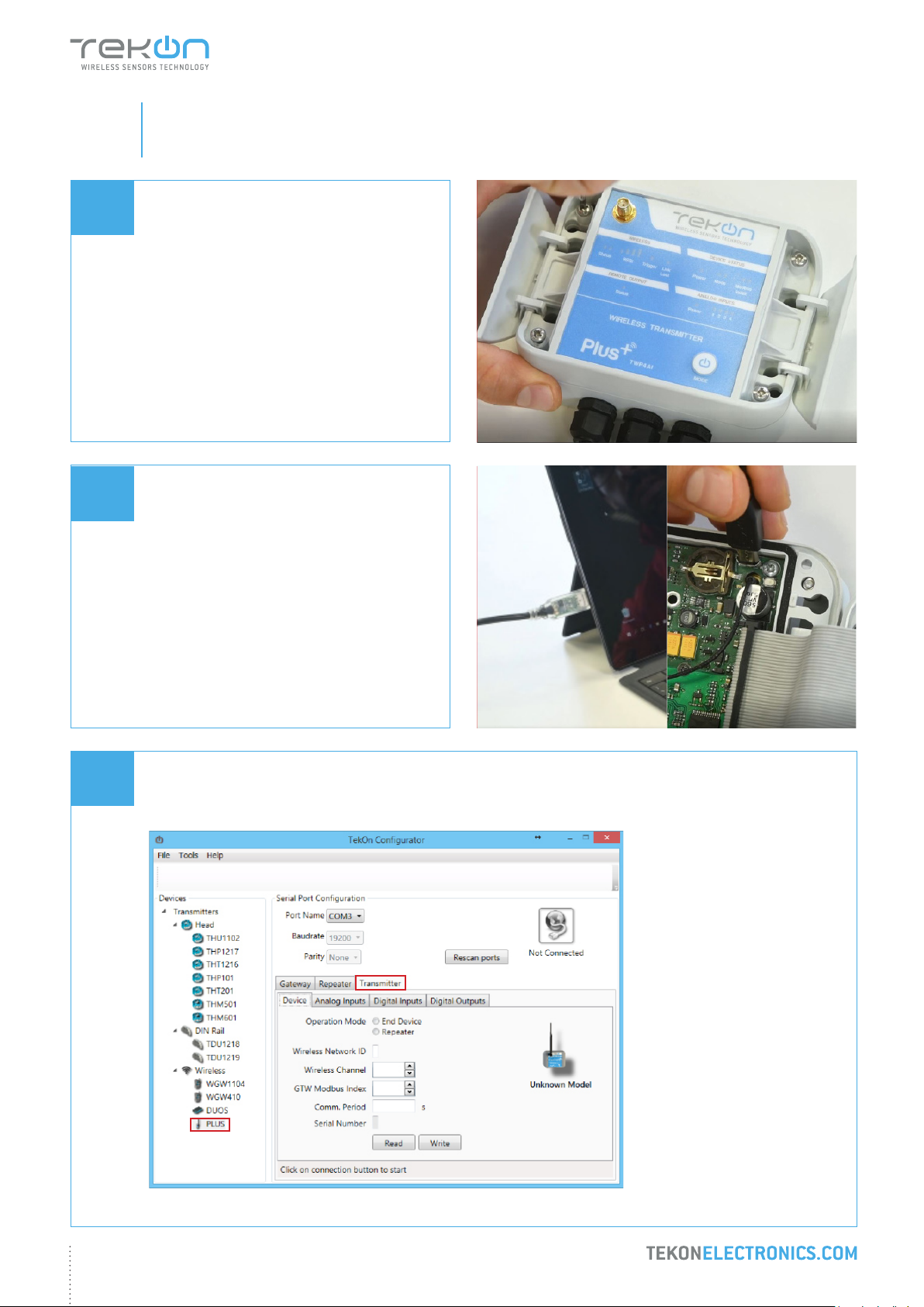
Loosen the 4 screws of the case and open it.
Connect a micro USB cable to the computer
and then to TWP4AI PLUS Wireless
Transmitter.
03
Open a new window of Tekon Congurator Software and select PLUS >> Transmitter menu.
2
1
14
Page 15
step
PLUS WIRELESS SYSTEM INSTALLATION GUIDE
02
04
04
TWP4AI PLUS WIRELESS TRANSMITTER CONFIGURATION
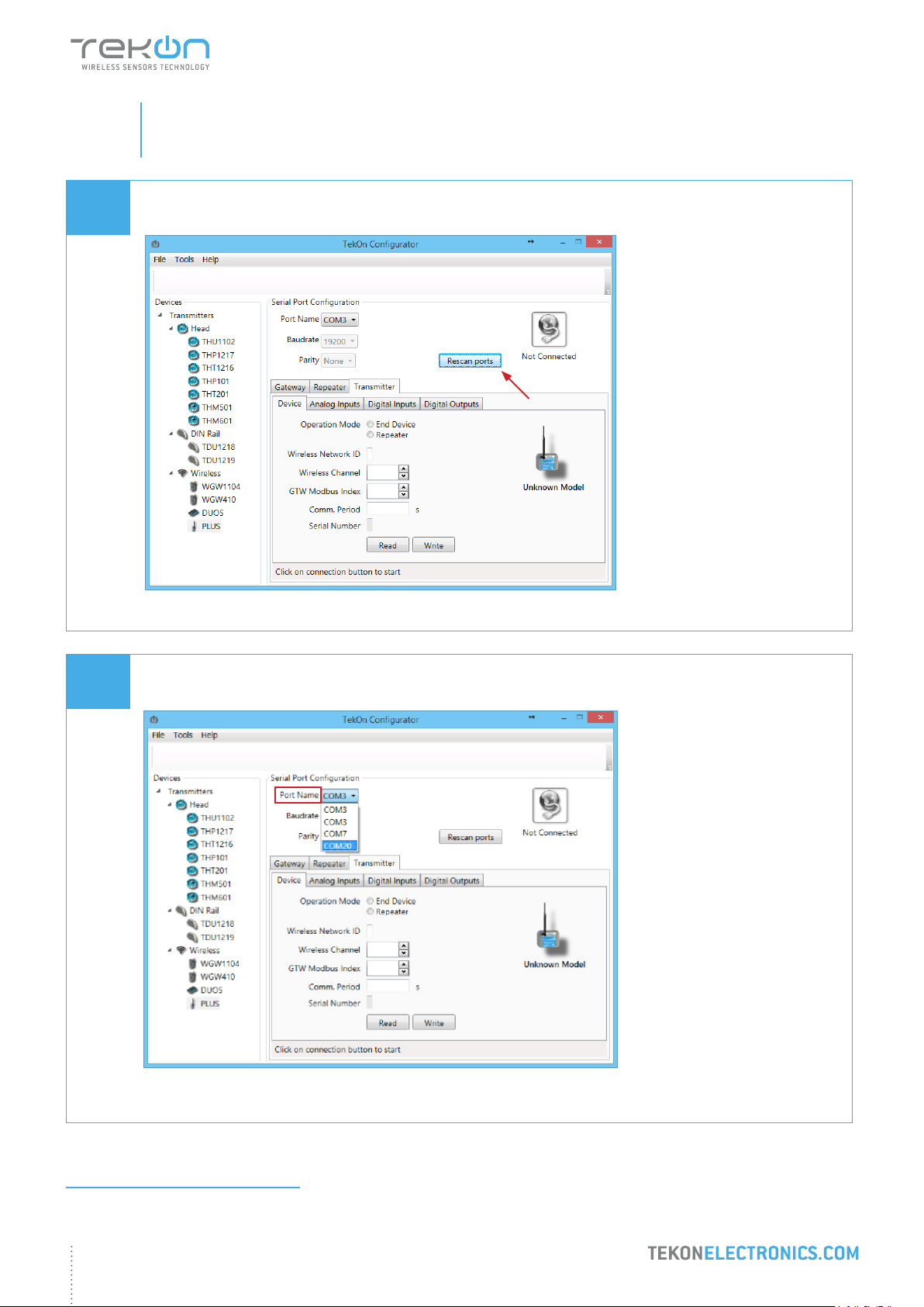
Click on Rescan Ports button.
05
Select corresponding Port name1.
1
You can check device’s serial port name in “Device Manager” on Microsoft® Windows® operating system.
15
Page 16
step
PLUS WIRELESS SYSTEM INSTALLATION GUIDE
02
06
TWP4AI PLUS WIRELESS TRANSMITTER CONFIGURATION
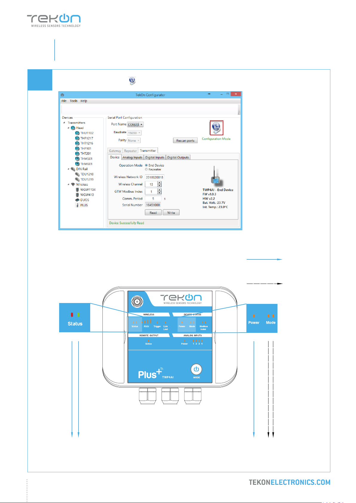
Click on Conguration Mode ( ) button.
ANALOG WIRELESS TRANSMITTER
LEDs
permanently
on
LEDs
alternating
16
Page 17
step
PLUS WIRELESS SYSTEM INSTALLATION GUIDE
02
07
TWP4AI PLUS WIRELESS TRANSMITTER CONFIGURATION
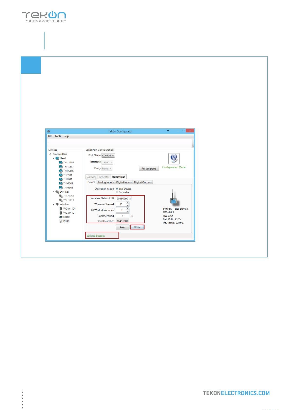
Congure Wireless Network ID and Wireless Channel previously obtained from Gateway.
The wireless connection between both devices is ensured by setting the same Wireless Network ID and Wireless
Channel parameters.
Gateway Modbus Index will dene the modbus registers window used to store information sent by the
transmitter.
Each transmitter should have a different Gateway Modbus Index in order to avoid information override.
Click on Write button to update Transmitter settings.
17
Page 18
step
PLUS WIRELESS SYSTEM INSTALLATION GUIDE
02
08
TWP4AI PLUS WIRELESS TRANSMITTER CONFIGURATION
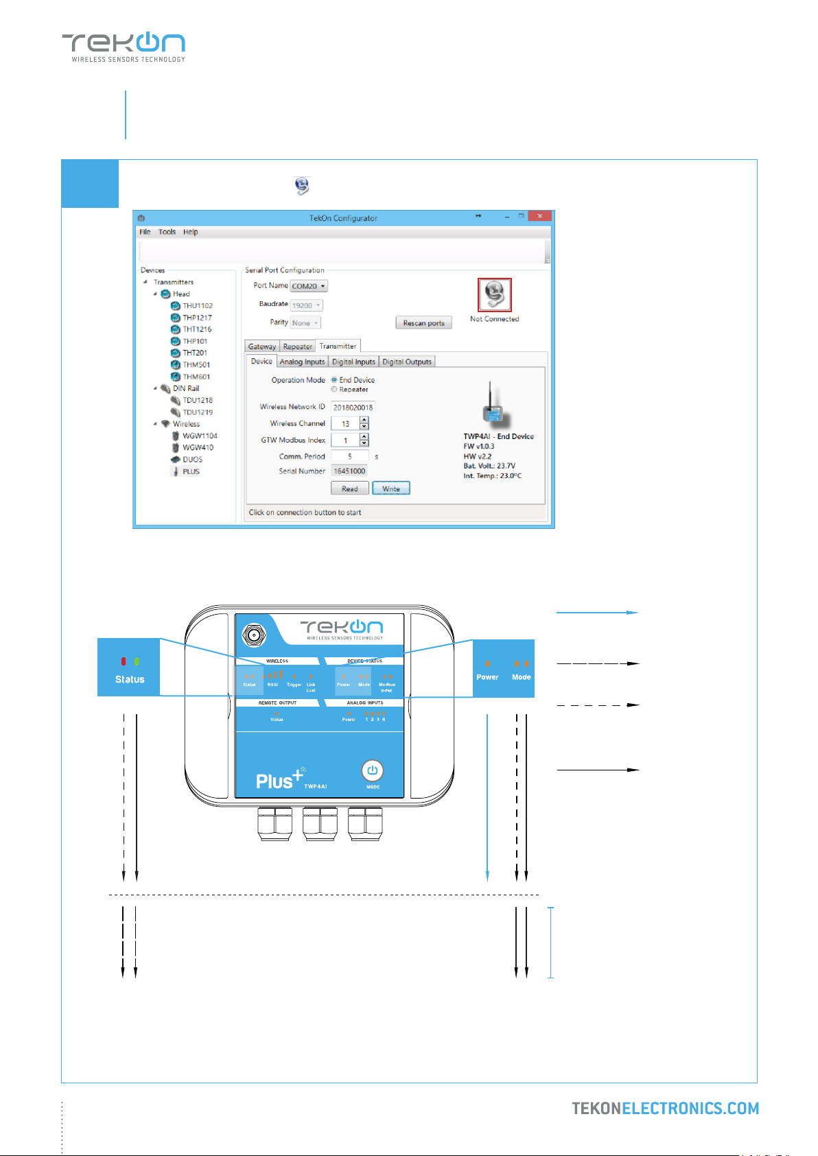
Click on Conguration Mode ( ) button to exit setup and resume normal operating mode.
ANALOG WIRELESS TRANSMITTER
LED
permanently
on
LEDs
alternating
LEDs ashing
until wireless
connection is
established
LED
permanently
off
When connected
to the Gateway
18
Page 19
step
PLUS WIRELESS SYSTEM INSTALLATION GUIDE
02
TWP4AI PLUS WIRELESS TRANSMITTER CONFIGURATION
After clicking on Disconnect button, the device will permanently attempt to connect to a wireless network.
If there is no communication, the Status LED ashes slowly and the Mode LED ashes quickly.
When there’s a successful connection directly to a wireless network, both status LEDs alternate quickly - during
1 minute if the transmitter is operating as end device or permanently if operating as repeater.
NOTE:
Make sure that the devices are at a distance of at least 3 meters or remove the antenna from the gateway (in
case both devices are near each other).
19
Page 20

step
03
TWP4AI TRANSMITTER ANALOG INPUT CONFIGURATION
Page 21
step
PLUS WIRELESS SYSTEM INSTALLATION GUIDE
03
01
02
TWP4AI TRANSMITTER ANALOG INPUT CONFIGURATION
NOTE:
By default, analog inputs are switched OFF for power optimization.
Each analog input can be congured independently, as current input [0..20mA] or voltage input [0..10V]
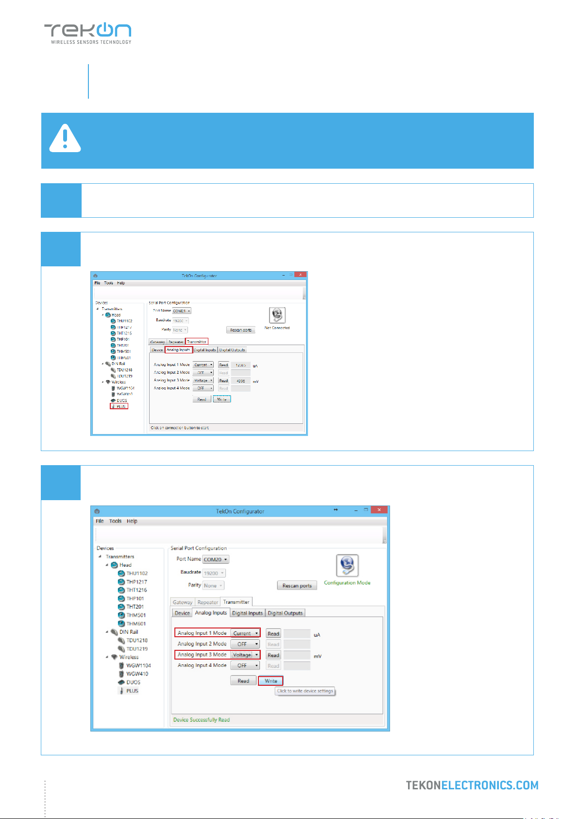
To enter in Conguration Mode follow steps 01 to 05 of PLUS Wireless Transmitter Conguration.
In Tekon Congurator Software select PLUS >> Transmitter >> Analog Inputs menu
2
3
03
1
Select Current option on Analog Input 1 and Voltage option on Analog Input 3 operation mode and click Write.
21
Page 22
step
PLUS WIRELESS SYSTEM INSTALLATION GUIDE
03
04
TWP4AI TRANSMITTER ANALOG INPUT CONFIGURATION
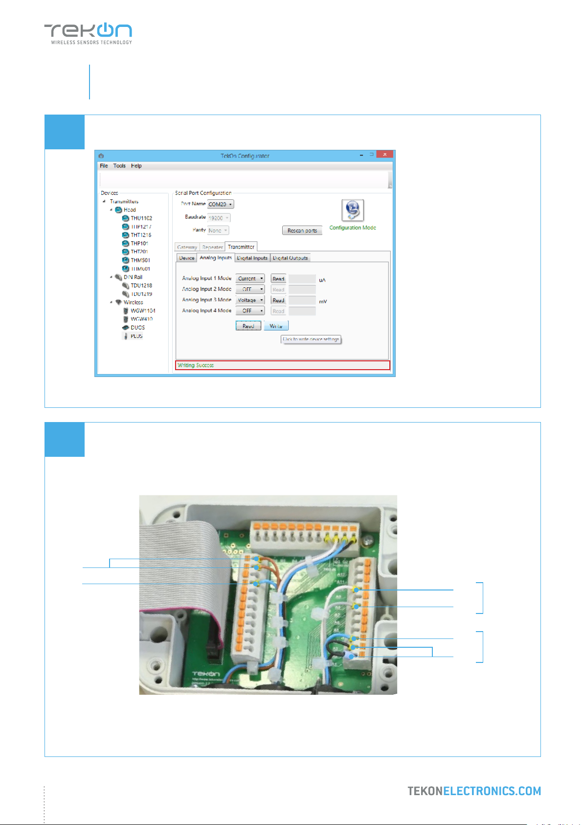
The status string at the bottom of the software window provides feedback on ongoing operations.
05
+24VDC
(GND)
Wiring
Wire the device according to the diagram below.
(GND)
V+
(GND)
I (mA)
Analog Input 3
Analog Input 1
22
Page 23
step
PLUS WIRELESS SYSTEM INSTALLATION GUIDE
03
06
TWP4AI TRANSMITTER ANALOG INPUT CONFIGURATION
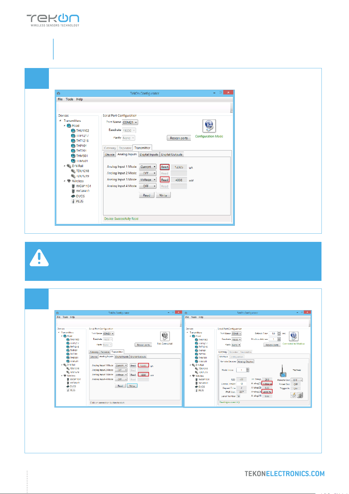
Validate conguration by clicking on Read button.
07
NOTE:
Conguration and Operation validated.
Measured value of current and voltage depend on the setup. In this example 12mA (12000uA) and 5V (5000
mV) are being injected.
Exit conguration mode and compare data sent by wireless communication.
23
Page 24

step
04
TWP4AI TRANSMITTER DIGITAL INPUT CONFIGURATION
Page 25
step
PLUS WIRELESS SYSTEM INSTALLATION GUIDE
04
01
02
TWP4AI TRANSMITTER DIGITAL INPUT CONFIGURATION
NOTE:
Sink type Digital Input.
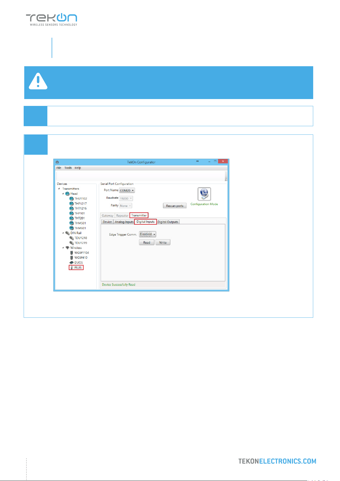
To enter in Conguration Mode follow steps 01 to 05 of PLUS Wireless Transmitter Conguration.
In Tekon Congurator Software select PLUS >> Transmitter >> Digital Inputs menu.
2
3
1
25
Page 26
step
PLUS WIRELESS SYSTEM INSTALLATION GUIDE
04
03
TWP4AI TRANSMITTER DIGITAL INPUT CONFIGURATION
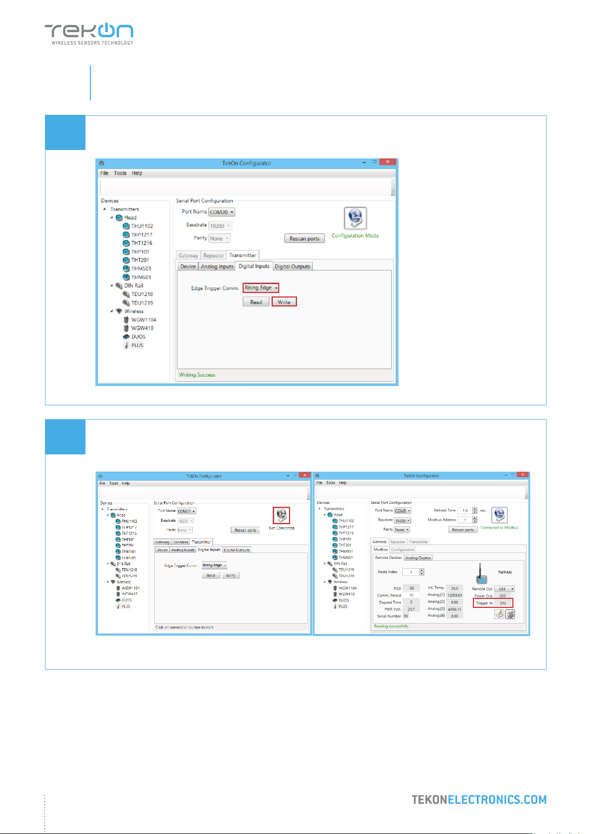
Select Operation Mode Rising Edge and click on Write button.
04
Validate functionality and click on Disconnect button.
Wait for the device to connect to the Gateway and observe data in Tekon Congurator window.
26
Page 27

step
05
TWP4AI TRANSMITTER DIGITAL OUTPUTS CONFIGURATION
Page 28
step
PLUS WIRELESS SYSTEM INSTALLATION GUIDE
05
01
02
TWP4AI TRANSMITTER DIGITAL OUTPUTS CONFIGURATION
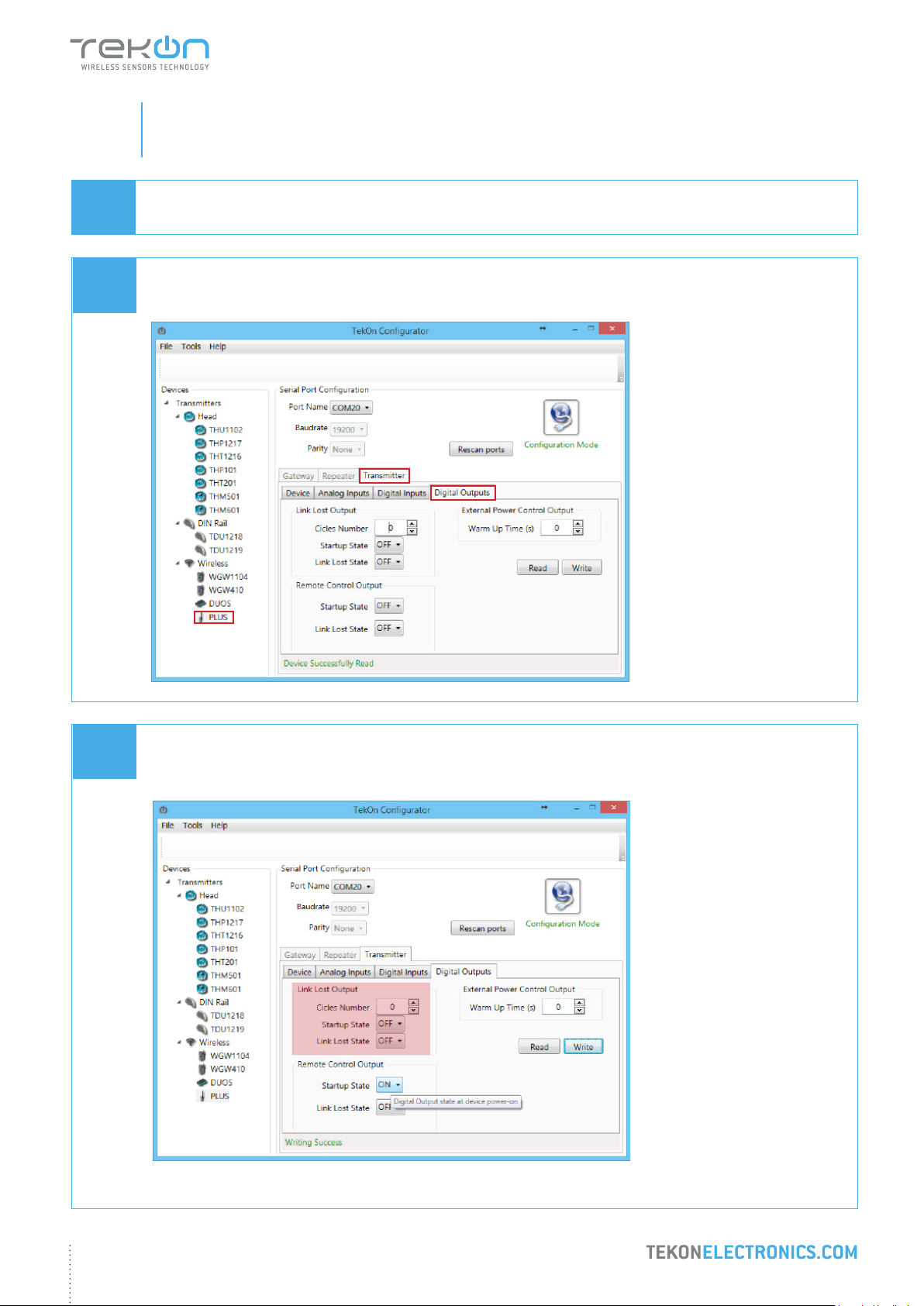
To enter in Conguration Mode follow steps 01 to 05 of PLUS Wireless Transmitter Conguration.
In Tekon Congurator Software select PLUS >> Transmitter >> Digital Outputs menu
2
3
03
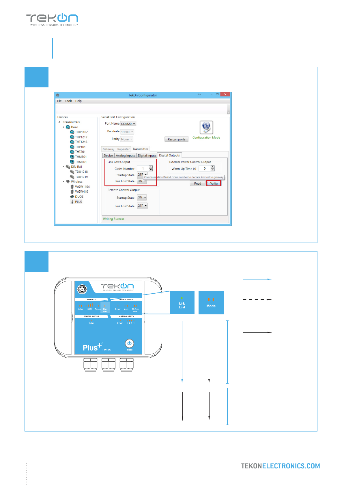
1
Link Lost Output
Output that outputs wireless connection state of the device.
28
Page 29
step
PLUS WIRELESS SYSTEM INSTALLATION GUIDE
05
03.1
TWP4AI TRANSMITTER DIGITAL OUTPUTS CONFIGURATION
Select cycle number, start-up state and link lost state and click on Write button.
03.2
Exit conguration mode and verify setup by checking LEDs indicators..
ANALOG WIRELESS TRANSMITTER
LED
permanently
on
Red LED
ashing
until wireless
connection is
established
LEDs
permanently
off
Connection to gateway not
established
Connection to gateway
established
29
Page 30
step
PLUS WIRELESS SYSTEM INSTALLATION GUIDE
05
04
04.1
TWP4AI TRANSMITTER DIGITAL OUTPUTS CONFIGURATION
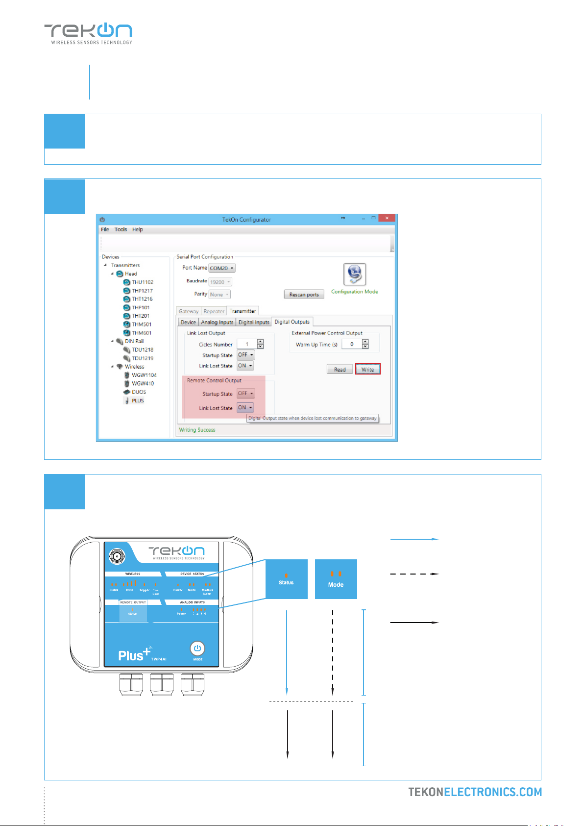
Remote Control Output
Digital output remotely controlled by Gateway modbus protocol.
Dene Start-up state and Link lost state. Click on Write button.
04.2
Exit conguration mode and verify setup by checking LEDs indicators.
LED
permanently on
Red LED
ashing until wireless
connection is
established
LEDs permanently off
ANALOG WIRELESS TRANSMITTER
Connection to gateway not
established
Connection to gateway
established
30
Page 31
step
PLUS WIRELESS SYSTEM INSTALLATION GUIDE
05
04.3
TWP4AI TRANSMITTER DIGITAL OUTPUTS CONFIGURATION
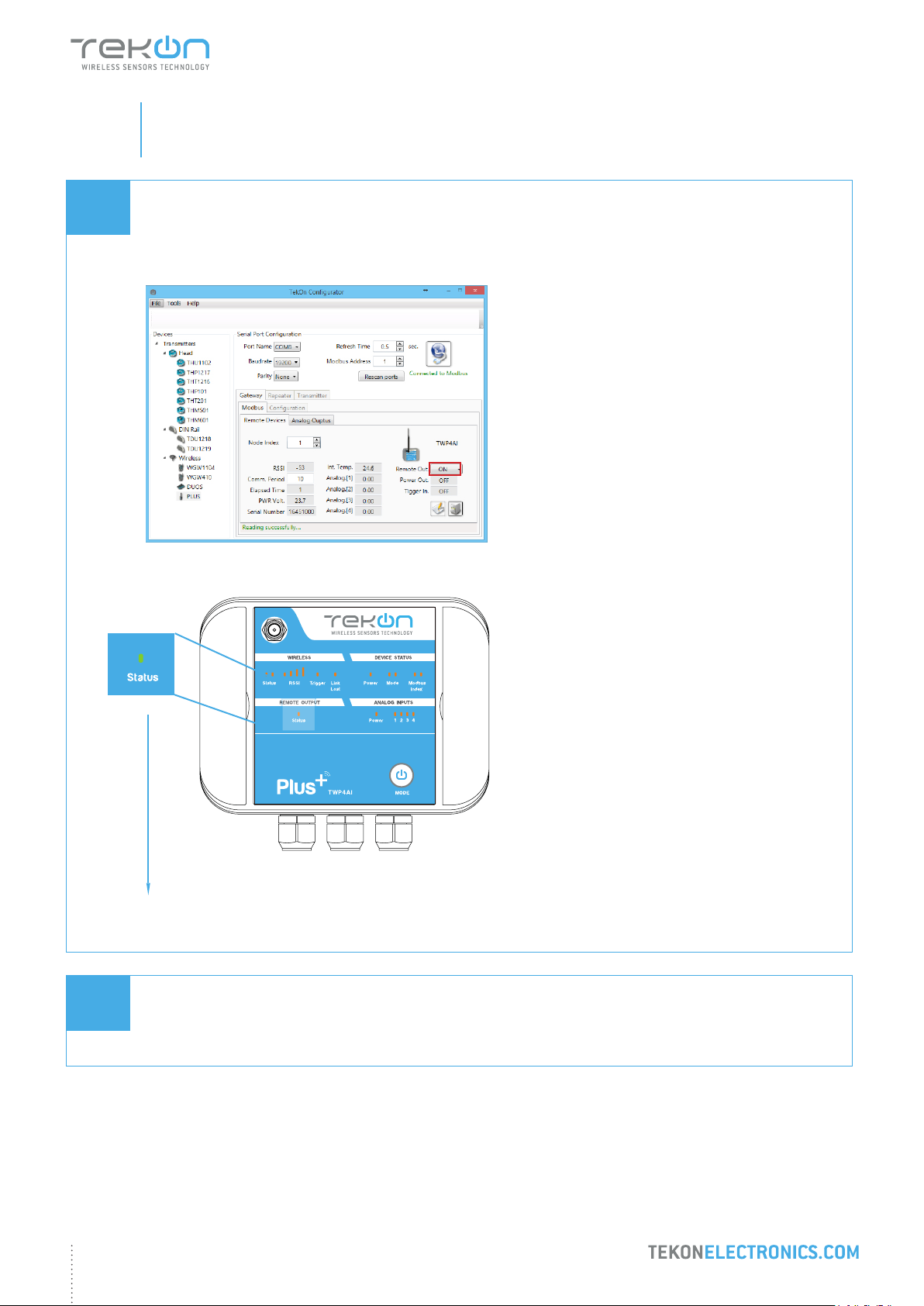
Using the Tekon Congurator you can change the State of Remote Output by setting the modbus register on the
gateway. The Gateway will send the information in the next time the transmitter performs a communication.
ANALOG WIRELESS TRANSMITTER
LED permanently on
05
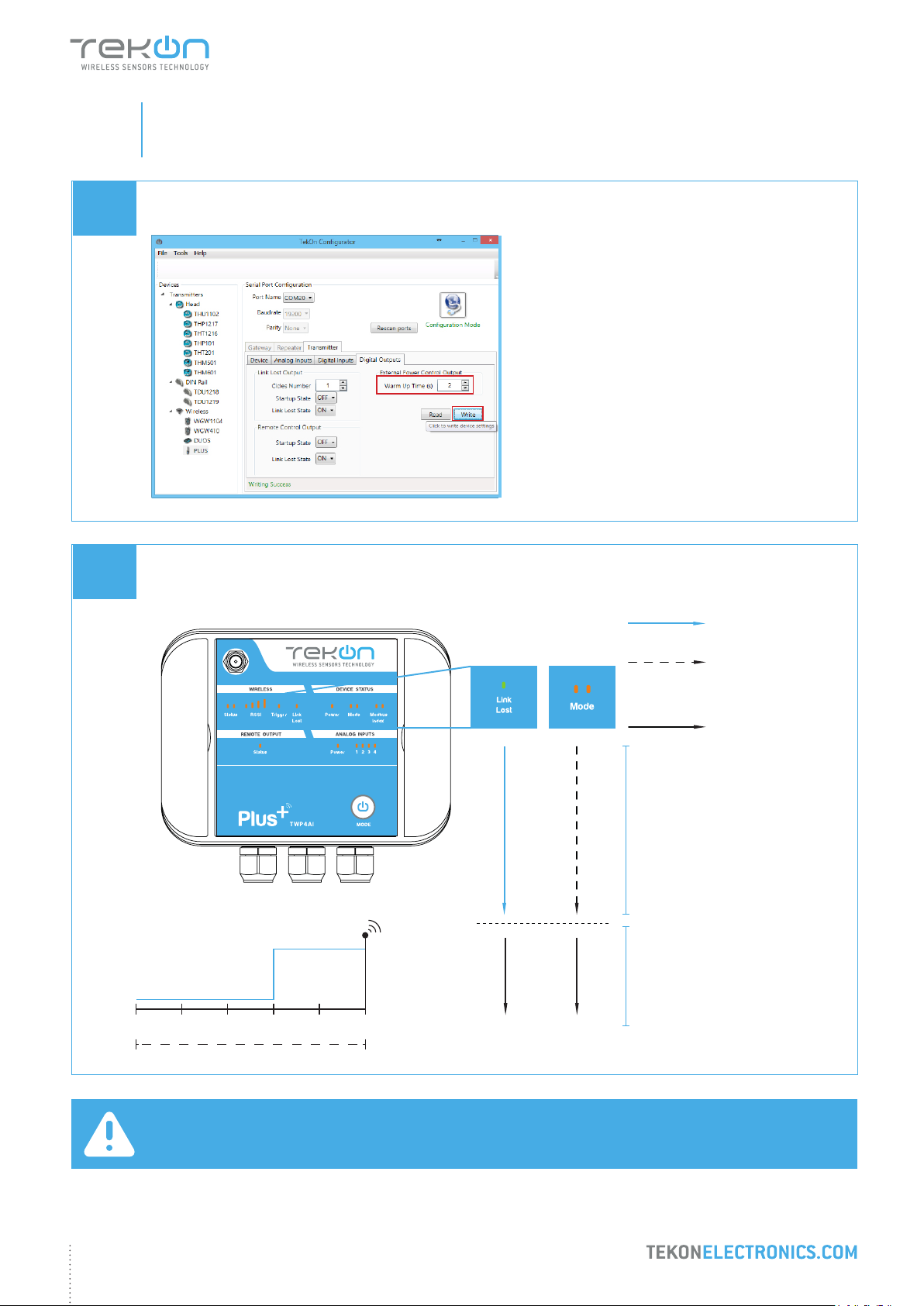
External Power Control Output
Time congurable output to power on an external device before data acquisition and transmission.
31
Page 32
step
PLUS WIRELESS SYSTEM INSTALLATION GUIDE
05
05.1
05.2
TWP4AI TRANSMITTER DIGITAL OUTPUTS CONFIGURATION
Dene Warm up time and click on the Write button.
Exit conguration mode and verify setup by checking LEDs indicators.
Output ON
Output OFF
ANALOG WIRELESS TRANSMITTER
OFF STATE
0
1 2 3 4 5
Communication Period
ON STATE
Warm-up Time
LED
permanently on
Red LED
ashing until wireless
connection is
established
LEDs permanently
off
Connection to Gateway
not established
Wireless transmission
Connection to Gateway
established
(sec)
NOTE:
Diagram only applies after the transmitter and gateway are connected.
32
Page 33

step
06
WGW420 GATEWAY ANALOG OUTPUTS CONFIGURATION
Page 34
step
PLUS WIRELESS SYSTEM INSTALLATION GUIDE
06
01
02
GATEWAY ANALOG OUTPUTS
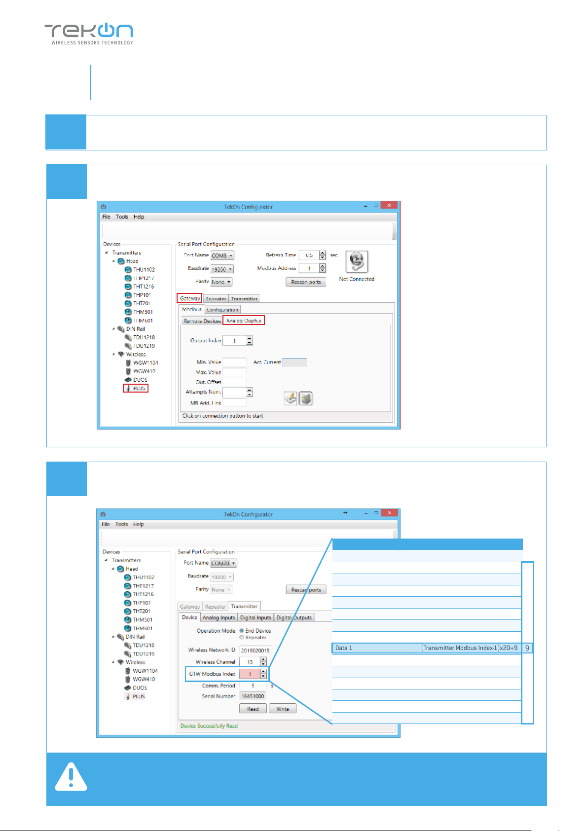
Follow steps 06 and 07 of the PLUS Wireless Gateway Conguration.
In Tekon Congurator Software select PLUS >> Gateway >> Analog Outputs menu
2
3
03
1
Considering the transmitter conguration with GTW Modbus Index=1, there is a Gateway Modbus Address
Window corresponding to Modbus address window [0-19].
HOLDING REGISTERS - TRANSMITTERS DATA
Description Address
Serial Number (Transmitter Modbus Index-1) x 20+0
Transmitter Model (Transmitter Modbus Index-1)x20+2
RSSI (Transmitter Modbus Index-1)x20+3
Communication Period (Transmitter Modbus Index-1)x20+4
Elapsed Time (Transmitter Modbus Index-1)x20+5
Power Voltage (Transmitter Modbus Index-1)x20+6
Data 0 (Transmitter Modbus Index-1)x20+7
Data 1 (Transmitter Modbus Index-1)x20+9
Data 2 (Transmitter Modbus Index-1)x20+11
Data 3 (Transmitter Modbus Index-1)x20+13
Data 4 (Transmitter Modbus Index-1)x20+15
FW Version Major Minor (Transmitter Modbus Index-1)x20+17
FW Version Revision (Transmitter Modbus Index-1)x20+18
HW Version Major Minor (Transmitter Modbus Index-1)x20+19
MB Add
0
9
19
NOTE:
Transmitter analog input 1 data is received and stored at the Gateway Modbus address [9].
34
Page 35
step
PLUS WIRELESS SYSTEM INSTALLATION GUIDE
06
04
GATEWAY ANALOG OUTPUTS
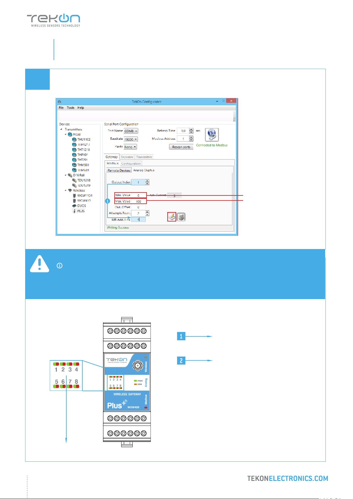
Link Analog Output Index 1 (Gateway) to Analog Input 1 (Transmitter) and congure MB Add Link according to
the previous step. Set minimum and maximum values and click on Write
4000 (4mA)
20000 (20mA)
NOTE:
Output index 1 is linked to modbus address [9], according to mapping table of step 03.
Modbus address double word (oat 32) value is converted into 4..20 mA scale according to minimum and
maximum dened values.
Green led permanently on
during a closed current loop
Red led permanently on
during an open current loop
WIRELESS GATEWAY
35
Page 36

step
07
WRP001 PLUS WIRELESS REPEATER CONFIGURATION
Page 37
step
PLUS WIRELESS SYSTEM INSTALLATION GUIDE
07
01
02
CONNECT AND CONFIGURE THE PLUS WIRELESS REPEATER
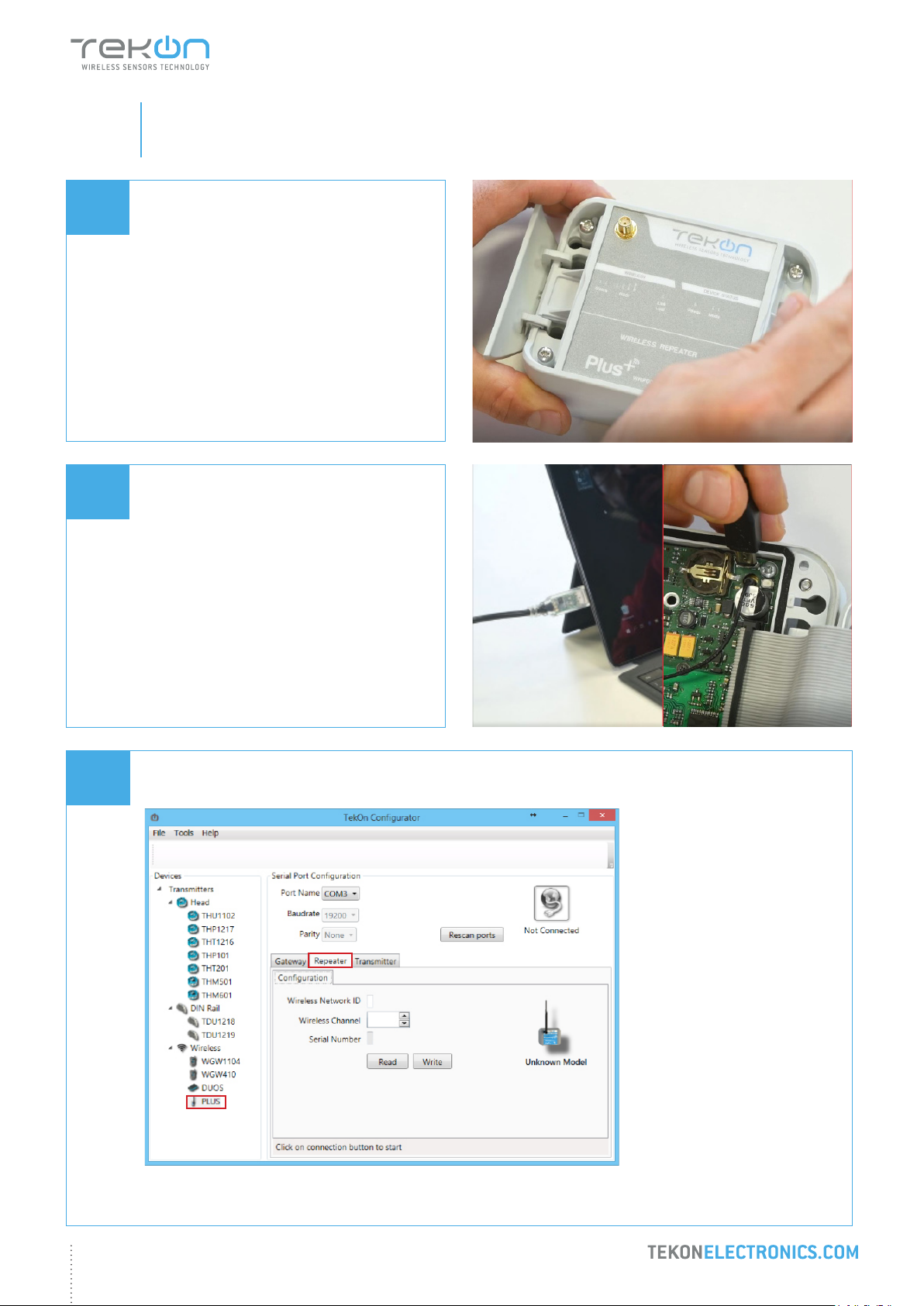
Loosen the 4 screws of the case and oppen it.
Connect a micro USB cable to the computer
and then to WRP001 PLUS Wireless Repeater.
03
Open a new window of Tekon Congurator Software and select PLUS >> Repeater menu.
2
1
37
Page 38
step
PLUS WIRELESS SYSTEM INSTALLATION GUIDE
07
04
CONNECT AND CONFIGURE THE PLUS WIRELESS REPEATER
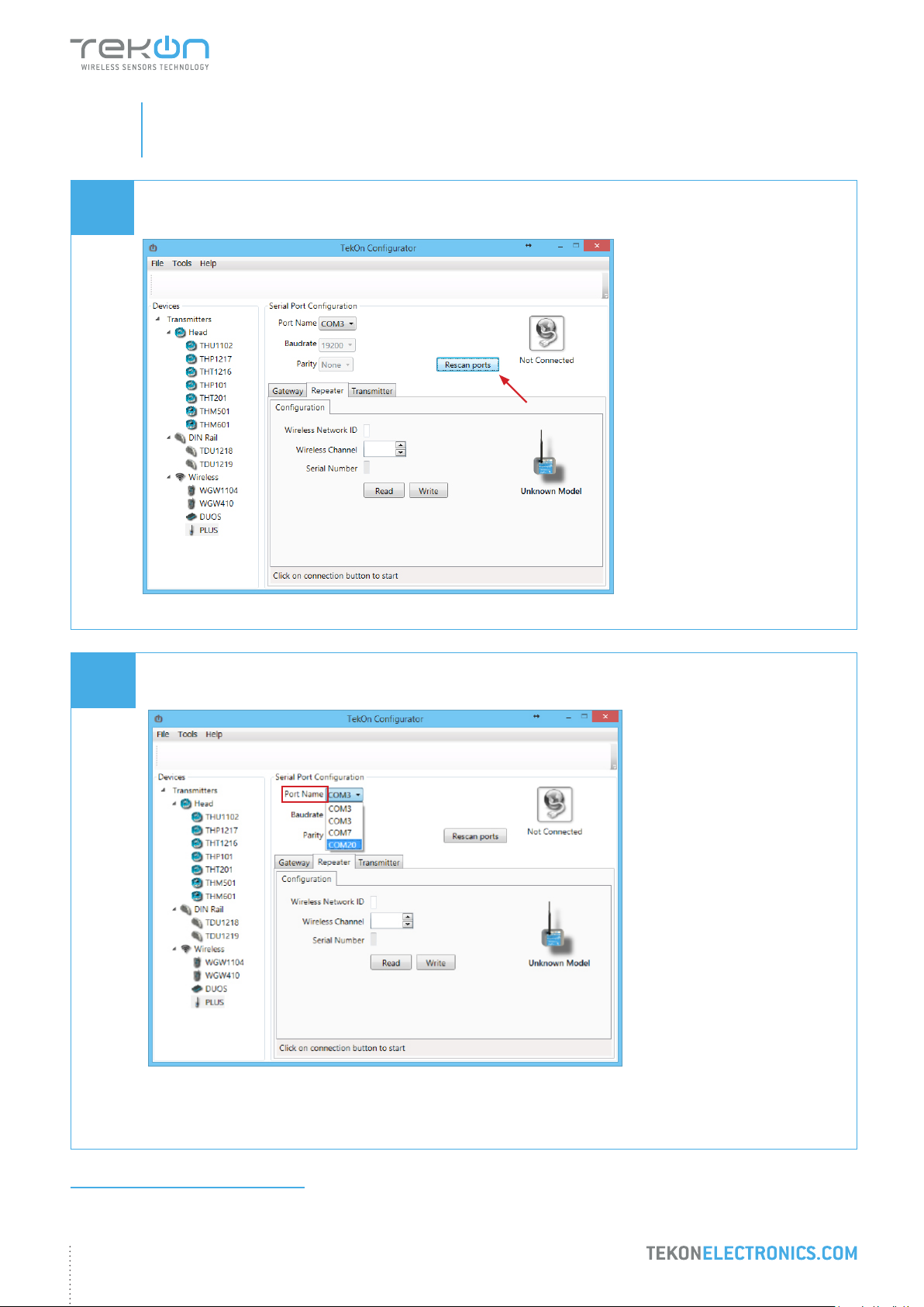
Click on Rescan Ports button.
05
Select corresponding Port name1.
1
You can check device’s serial port name in “Device Manager” on Microsoft® Windows® operating system.
38
Page 39
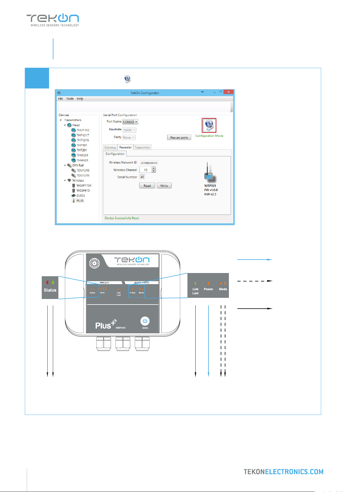
step
PLUS WIRELESS SYSTEM INSTALLATION GUIDE
07
06
CONNECT AND CONFIGURE THE PLUS WIRELESS REPEATER
Click on Conguration Mode ( ) button.
LED
permanently
on
LEDs ashing
until wireless
connection is
established
ANALOG WIRELESS TRANSMITTER
WIRELESS REPEATER
LED
permanently
off
39
Page 40
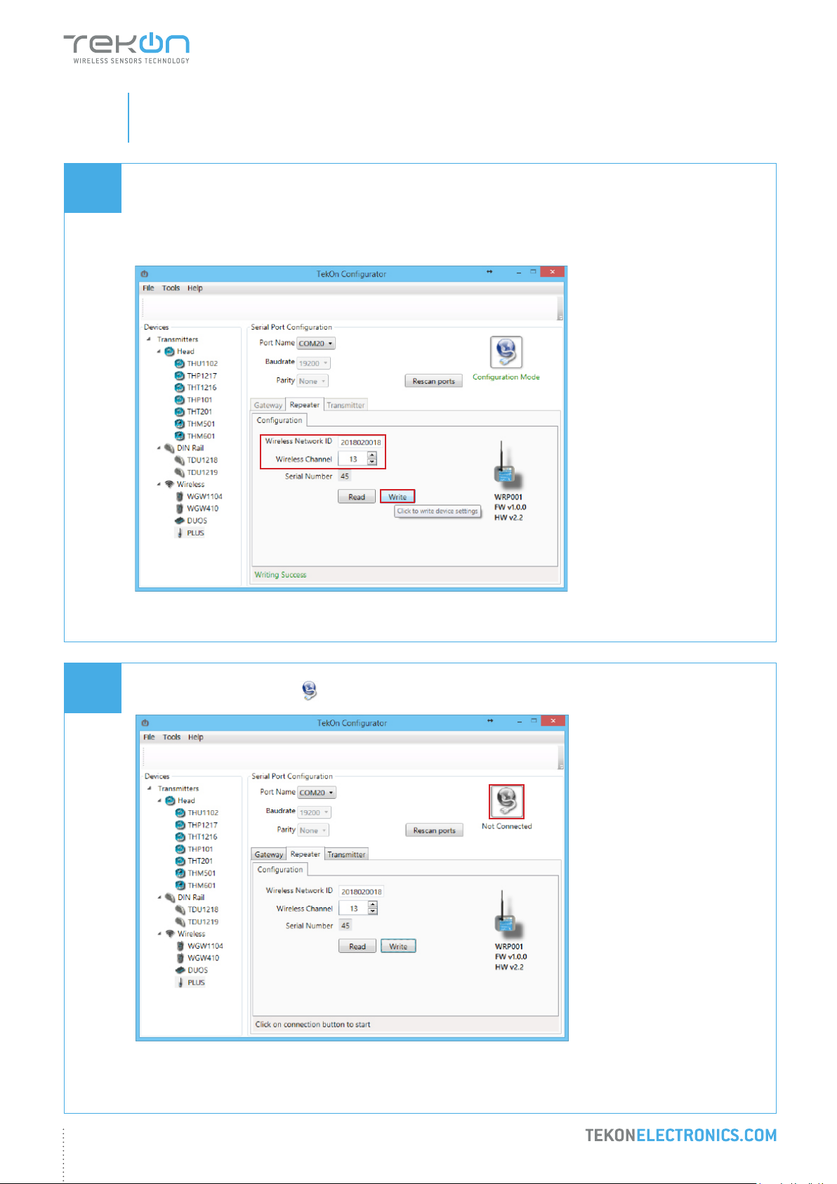
step
PLUS WIRELESS SYSTEM INSTALLATION GUIDE
07
07
CONNECT AND CONFIGURE THE PLUS WIRELESS REPEATER
Congure Wireless Network ID and Wireless Channel previously obtained from Gateway.
Click on Write button to update Transmitter settings.
08
Click on Conguration Mode ( ) button to exit setup and resume normal operating mode.
40
Page 41
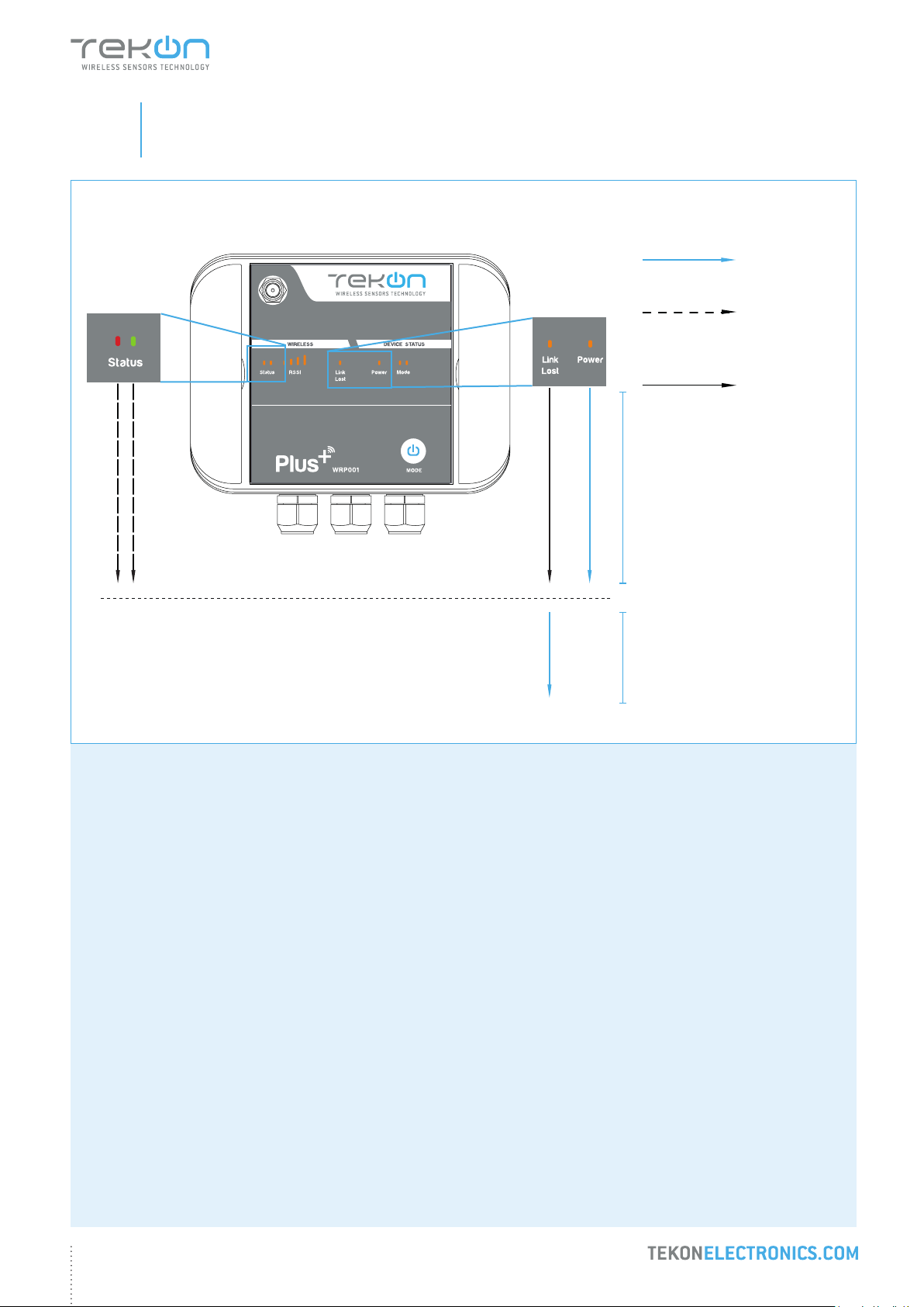
step
PLUS WIRELESS SYSTEM INSTALLATION GUIDE
07
CONNECT AND CONFIGURE THE PLUS WIRELESS REPEATER
ANALOG WIRELESS TRANSMITTER
WIRELESS REPEATER
LED
permanently
on
LEDs ashing
until wireless
connection is
established
LED
permanently
off
Connection to the Gateway
established
Connection to the Gateway
not established
41
Page 42

step
08
SITE SURVEY MODE
Page 43
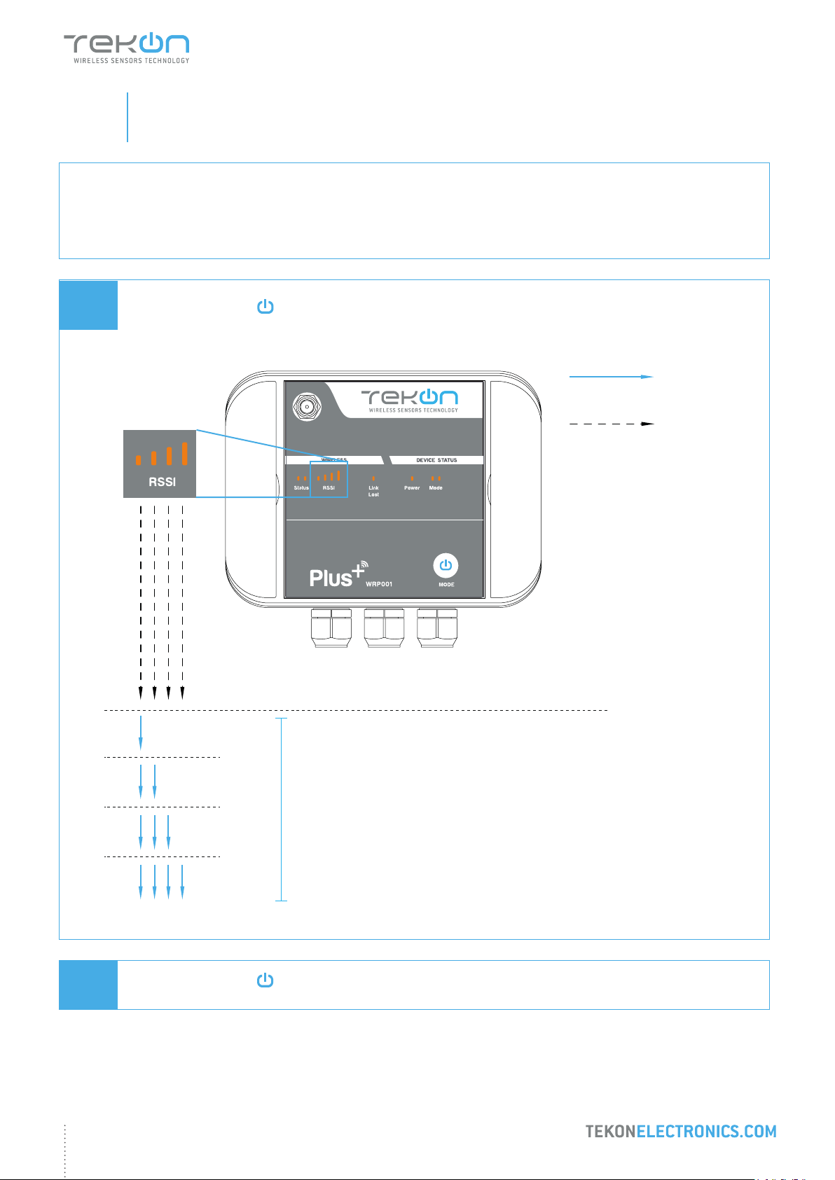
step
PLUS WIRELESS SYSTEM INSTALLATION GUIDE
08
01
SITE SURVEY MODE
Refers to following devices: THP4AI Transmitter and WRP001 Repeater.
Site survey mode is a tool that allows a quick wireless signal strength evaluation at the site of installation. It
doesn’t require additional equipment or software.
Press and hold Mode ( ) button untill Status LEDs are permanently on and Mode LEDs ash.
RSSI LEDs indicate the signal strength.
LED
permanently
on
LEDs ashing
until wireless
connection is
established
ANALOG WIRELESS TRANSMITTER
WIRELESS REPEATER
Connection Lost
LOW
02
MEDIUM
GOOD
EXCELLENT
Press and hold Mode ( ) button untill RSSI LEDs switch off and device resumes normal operation mode.
Connection to the Gateway established
RSSI communication level
43
Page 44

TEKON ELECTRONICS
a brand of Bresimar Automação S.A.
Quinta do Simão
3800-230 Aveiro
PORTUGAL
Sales
P.: +351 234 303 320
M.: +351 933 033 250
Technical Support
 Loading...