

Tekon PLUS TWP4AI, PLUS WRP001, PLUS WGW420 Installation Manual
PLUS WIRELESS SYSTEM
INSTALLATION GUIDE
TEKON ELECTRONICS AVEIRO, PORTUGAL
TEKON ELECTRONICS AVEIRO, PORTUGAL
P.: +351 234 303 320 M.: +351 933 033 250 E.: sales@tekonelectronics.com
P.: +351 234 303 320 M.: +351 933 033 250 E.: sales@tekonelectronics.com
IG.PLUS.ENG.V01.1.2018

PLUS WIRELESS SYSTEM
INSTALLATION GUIDE
Table of contents
DUOS WIRELESS SYSTEM INSTALLATION GUIDE
step
01
step
02
step
03
WGW420 PLUS WIRELESS GATEWAY CONFIGURATION
Pages 4 to 12
TWP4AI PLUS WIRELESS TRANSMITTER CONFIGURATION
Pages 13 to 19
TWP4AI TRANSMITTER ANALOG INPUT CONFIGURATION
Pages 20 to 23
step
04
2
TWP4AI TRANSMITTER DIGITAL INPUT CONFIGURATION
Pages 24 to 26

PLUS WIRELESS SYSTEM
INSTALLATION GUIDE
Table of contents
DUOS WIRELESS SYSTEM INSTALLATION GUIDE
step
05
step
06
TWP4AI TRANSMITTER DIGITAL OUTPUTS CONFIGURATION
Pages 27 to 32
5.1 LINK LOST OUTPUT
Page 28
5.2 REMOTE CONTROL OUTPUT
Page 30
5.3 EXTERNAL POWER CONTROL OUTPUT
Page 31
WGW420 GATEWAY ANALOG OUTPUTS CONFIGURATION
Pages 33 to 35
step
07
step
08
3
WRP001 PLUS WIRELESS REPEATER CONFIGURATION
Pages 36 to 41
SITE SURVEY MODE
Pages 42 and 43

step
01
WGW420 PLUS WIRELESS GATEWAY CONFIGURATION
step
PLUS WIRELESS SYSTEM INSTALLATION GUIDE
01
01
02
WGW420 PLUS WIRELESS GATEWAY CONFIGURATION
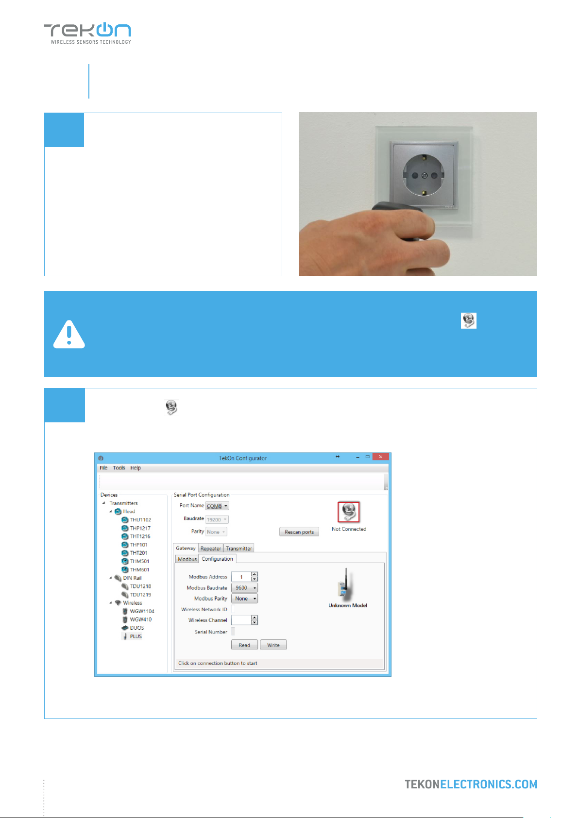
TEKON CONFIGURATOR SOFTWARE is only compatible with the Microsoft® Windows® Operating System.
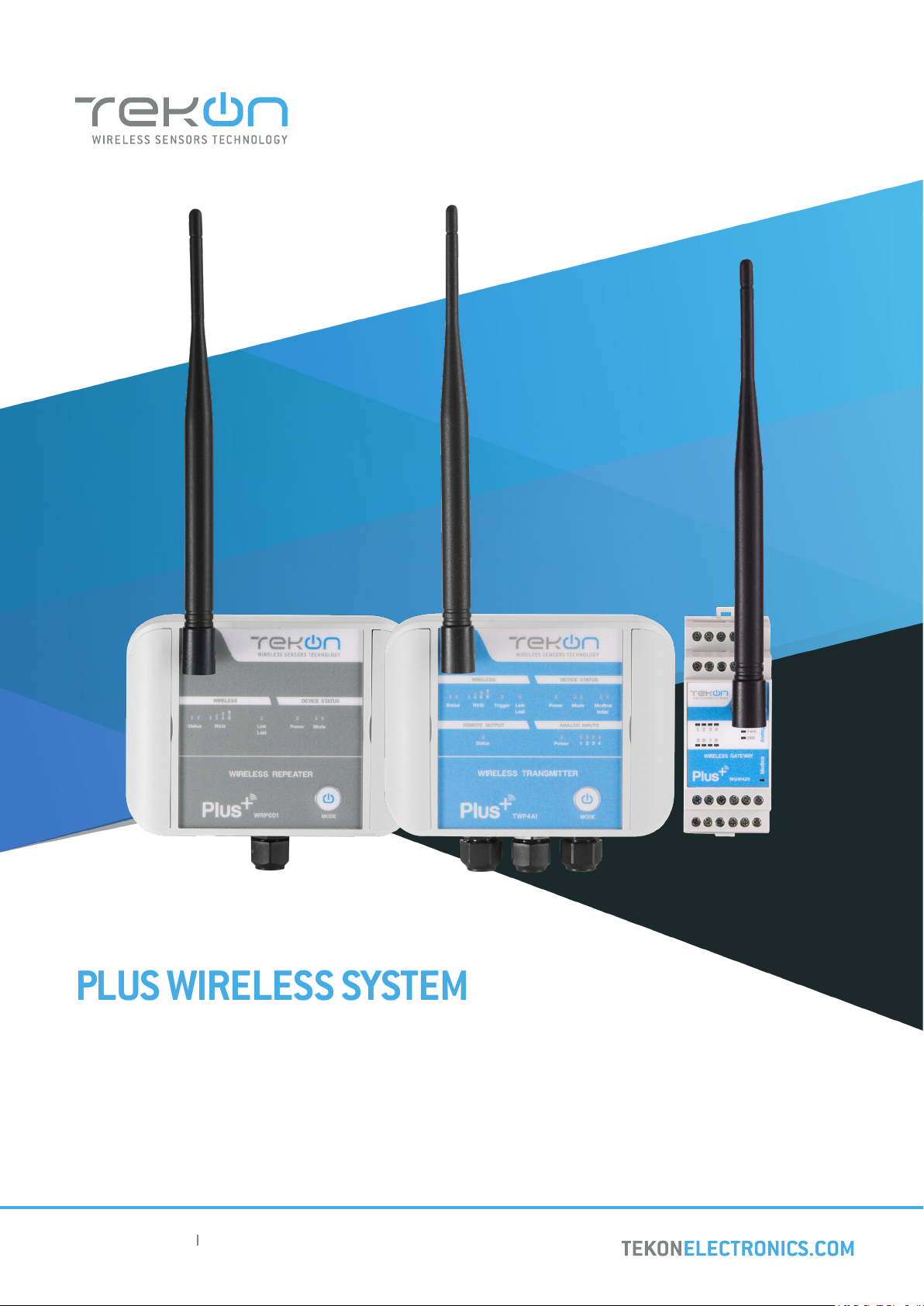
Connect the antenna to the Gateway.
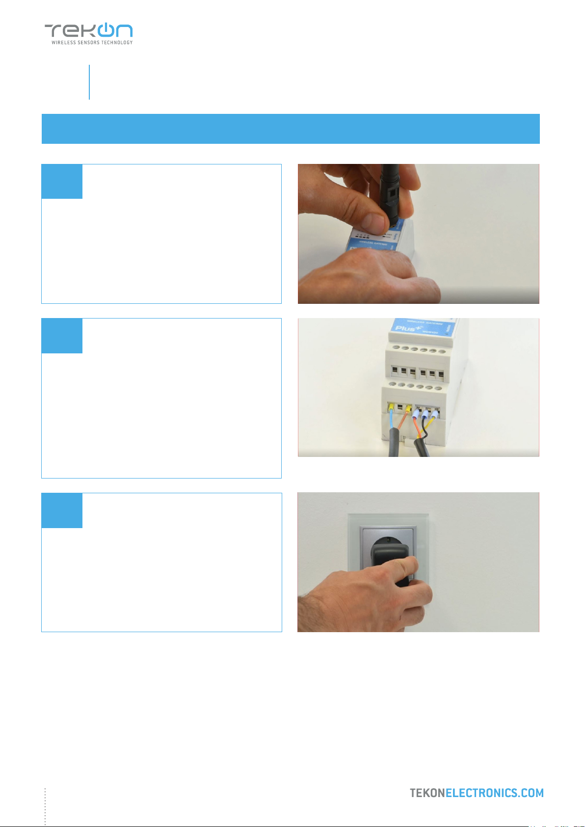
Wiring
Connect the power supply and then the
RS485-USB cable to the Gateway.
Wire Indication:
Blue - GND; Brown - +24 VDC; Orange - Data+ (A); Black - GND; Yellow - Data - (B)
03
Power ON the device.
5
step
PLUS WIRELESS SYSTEM INSTALLATION GUIDE
01
04
WGW420 PLUS WIRELESS GATEWAY CONFIGURATION
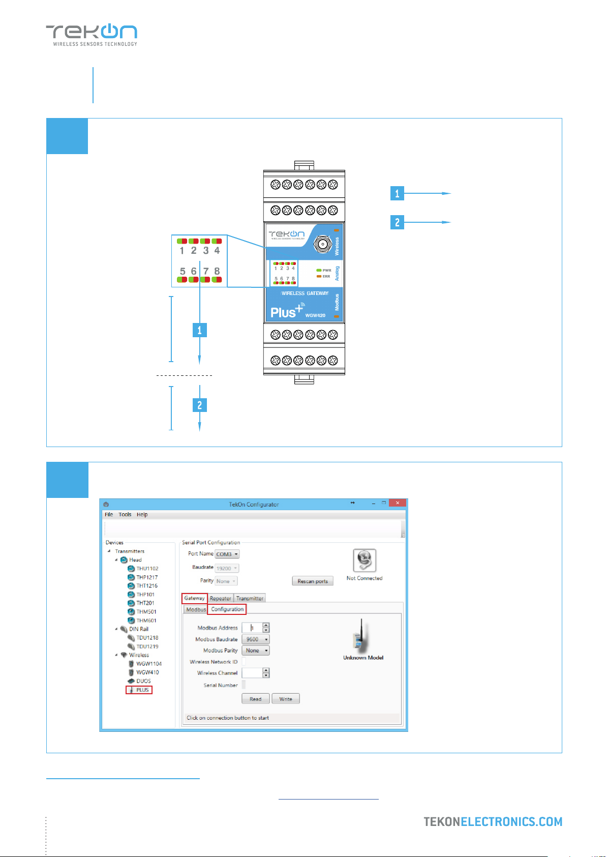
Check device connection state by LED indication.
Green LEDs
permanently on
Red LEDs
permanently on
WIRELESS GATEWAY
10 Seconds to enter
conguration mode
05
Normal mode
Open Tekon Congurator Software1 and select PLUS >> Gateway >> Conguration
2
3
1
1
Tekon Congurator software is free of charge and available at www.tekonelectronics.com
6
step
PLUS WIRELESS SYSTEM INSTALLATION GUIDE
01
06
WGW420 PLUS WIRELESS GATEWAY CONFIGURATION
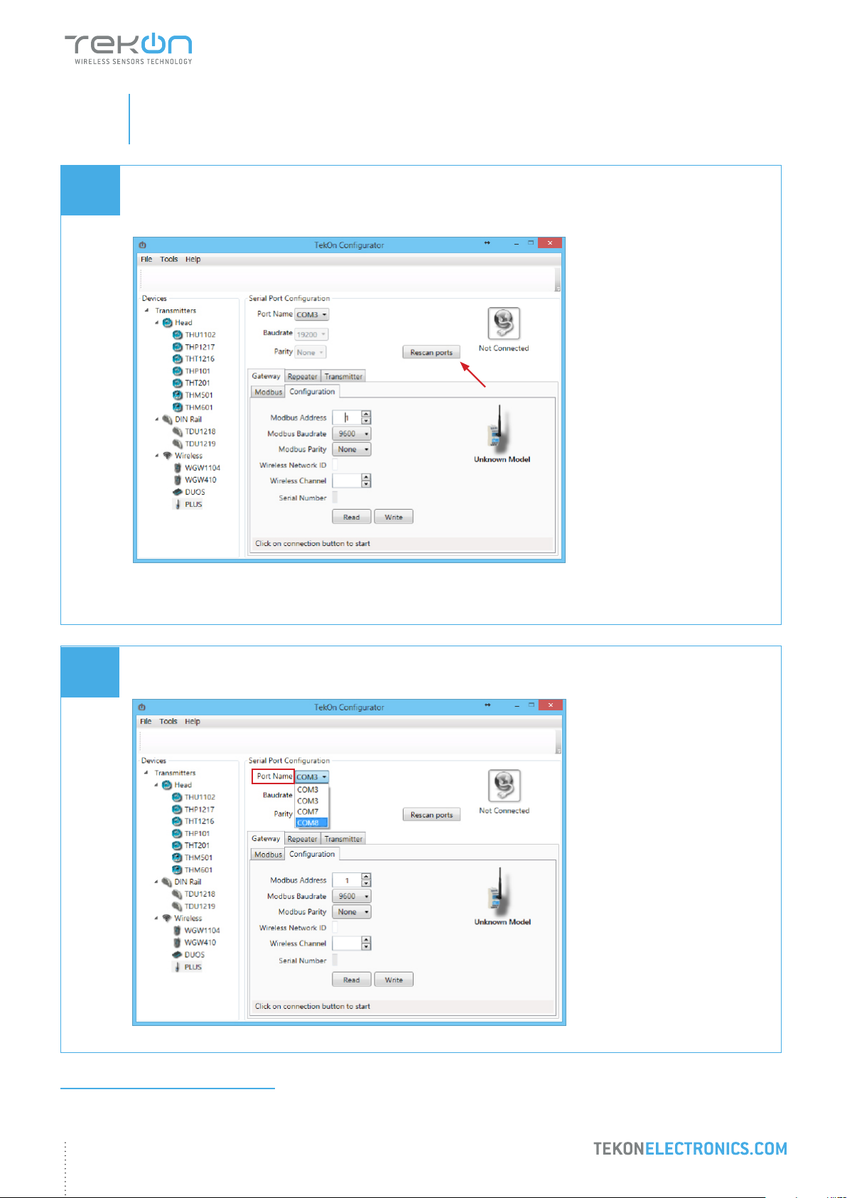
Select serial port corresponding to WGW420 PLUS Wireless Gateway
Click on the Rescan Ports button.
07
Select corresponding Port name2.
2
You can check device’s serial port name in “Device Manager” on Microsoft ® Windows® operating system.
7
step
PLUS WIRELESS SYSTEM INSTALLATION GUIDE
01
08
WGW420 PLUS WIRELESS GATEWAY CONFIGURATION
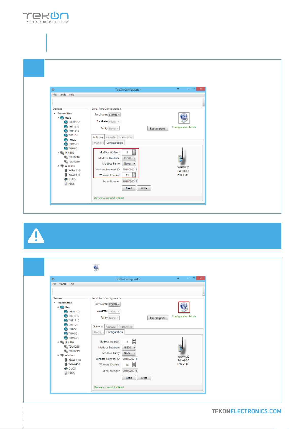
Perform a power cycle on the Gateway.
NOTE:
After power up, you have 10 seconds to enter conguration mode by clicking on Connect button ( )
(while green LEDs are permanently on).
In this mode, you can manage device parameters: Modbus Address, Modbus Baudrate, Modbus Parity, Wireless
Network ID and Wireless Channel.
09
Click on Connect ( ) button to enter conguration mode.
8

step
PLUS WIRELESS SYSTEM INSTALLATION GUIDE
01
09
WGW420 PLUS WIRELESS GATEWAY CONFIGURATION
The status string at the bottom of the software window provides feedback on ongoing operations.
You can also verify conguration mode activation by checking LEDs on the gateway.
Conguration mode
NOTE:
When the 10-second time frame to enter conguration mode is exceeded, the LEDs will turn permanently red and
the gateway will enter normal operation mode.
To re-enter conguration mode, a power reset must be performed - step 8.
Green LEDs performing
scan animation
WIRELESS GATEWAY
9
step
PLUS WIRELESS SYSTEM INSTALLATION GUIDE
01
10
WGW420 PLUS WIRELESS GATEWAY CONFIGURATION
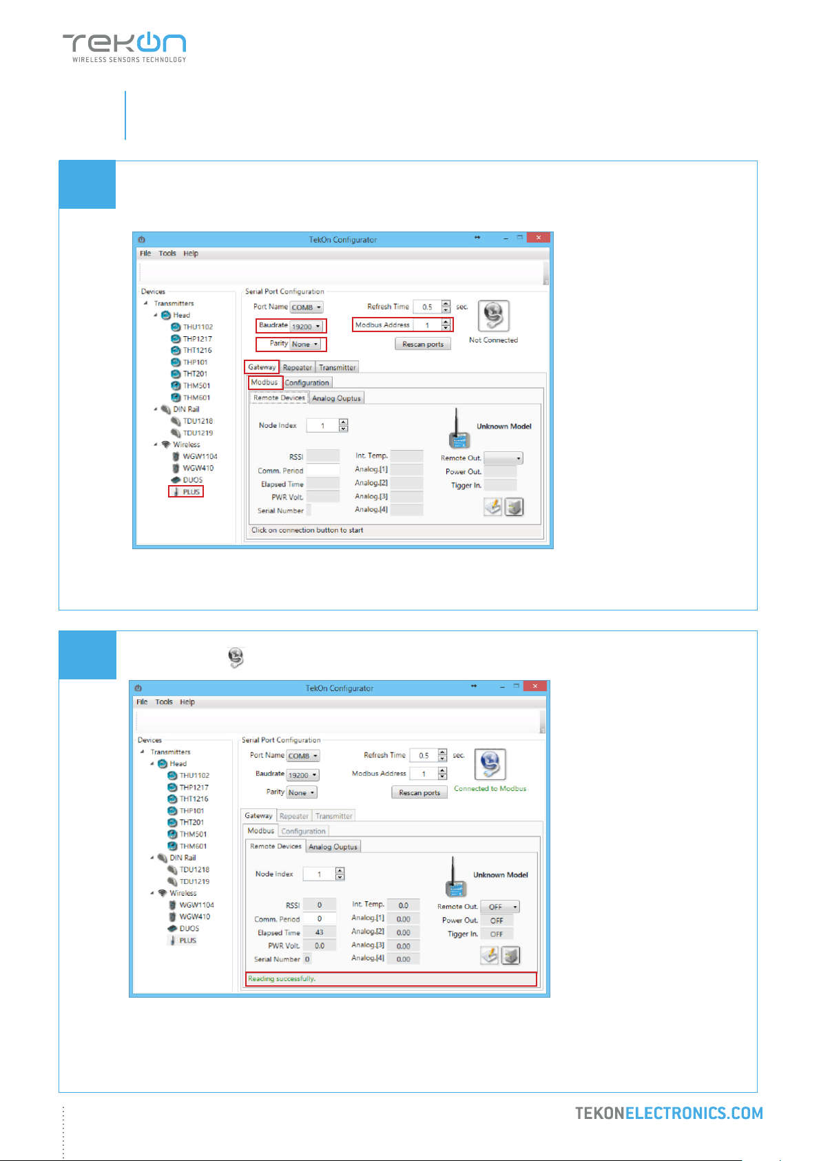
Take note of device conguration data available, namely: Modbus Address, Modbus Baudrate, Modbus Parity,
Wireless Network ID and Wireless Channel.
11
NOTE:
The wireless network connection between devices is ensured by setting the same Wireless Network ID and
Wireless Channel parameters.
Click on Disconnect ( ) button.
10
step
PLUS WIRELESS SYSTEM INSTALLATION GUIDE
01
12
WGW420 PLUS WIRELESS GATEWAY CONFIGURATION
Modbus Communication
Select Modbus tab of the Gateway and set the previously saved congurations.
13
Ensure that Port name, Baudrate, Parity and Modbus Address elds are the same as those obtained in
conguration mode.
Click on Connect ( ) button and check operation status at the bottom of the window.
11
The messages Connected to Modbus and Reading successfully will appear if Serial Port conguration parameters
are correct and the Modbus connection is established.
step
PLUS WIRELESS SYSTEM INSTALLATION GUIDE
01
WGW420 PLUS WIRELESS GATEWAY CONFIGURATION
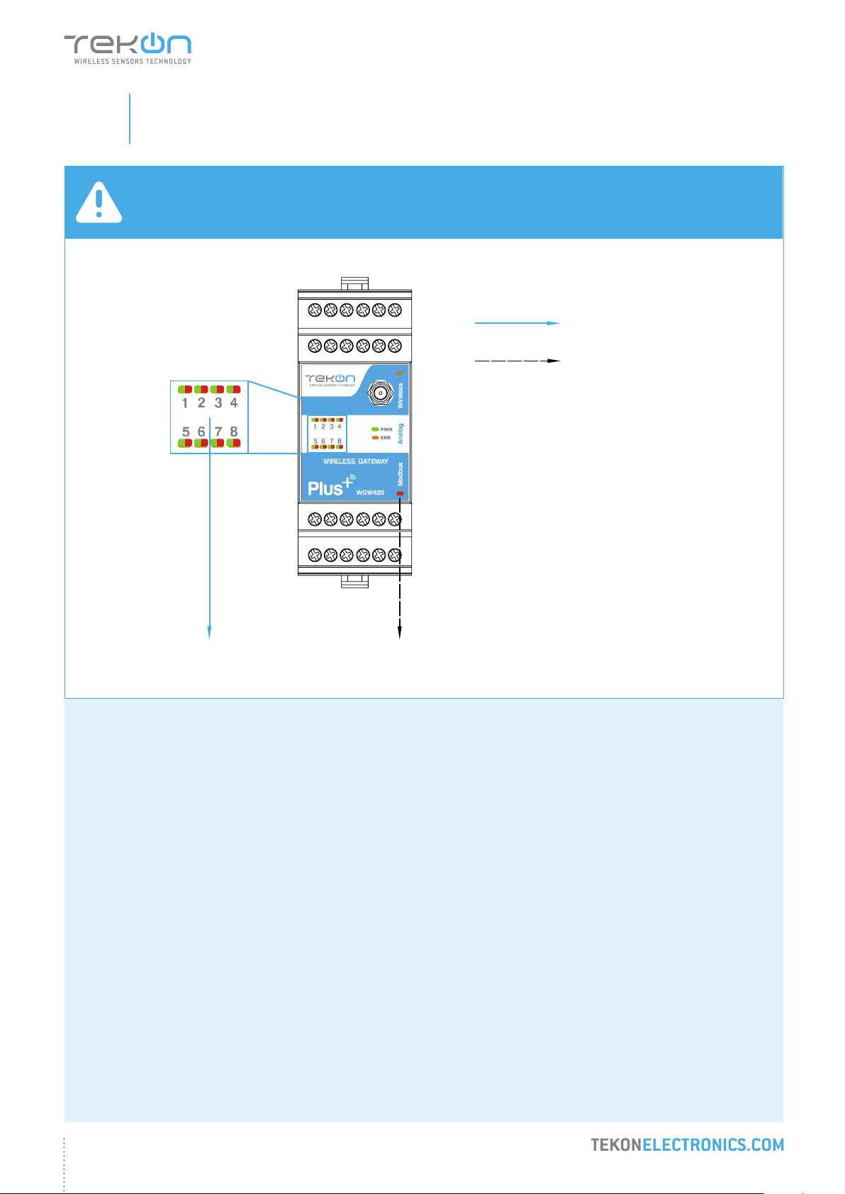
NOTE:
See WGW420 Datasheet to access LED indication information - page 4.
Red LEDs permanently on
LED ashes on each wireless
communication
WIRELESS GATEWAY
12

step
02
TWP4AI PLUS WIRELESS TRANSMITTER CONFIGURATION
step
PLUS WIRELESS SYSTEM INSTALLATION GUIDE
02
01
02
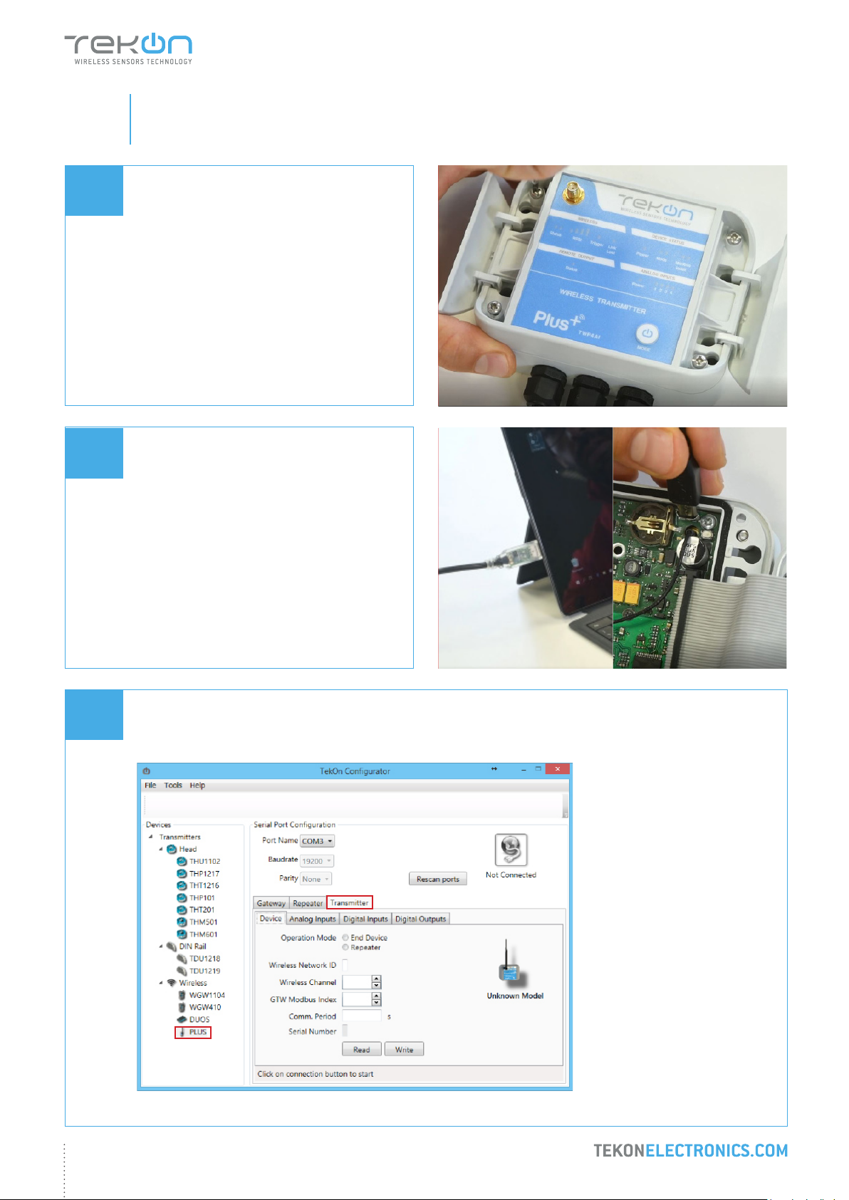
TWP4AI PLUS WIRELESS TRANSMITTER CONFIGURATION
Loosen the 4 screws of the case and open it.
Connect a micro USB cable to the computer
and then to TWP4AI PLUS Wireless
Transmitter.
03
Open a new window of Tekon Congurator Software and select PLUS >> Transmitter menu.
2
1
14
 Loading...