

Page 1
Research and Development Center
TEKO
CONTROL KEYPAD
Operation Manual
Page 2

Contents
Terms and Abbreviations ............................................................................. 3
1 Application ................................................................................................ 4
2 Technical Specifications .......................................................................... 5
3 Delivery Set ............................................................................................... 6
4 Structure .................................................................................................... 6
5 Key Functions ........................................................................................... 8
5.1 Main Keyboard ....................................................................................... 8
5.2 Auxiliary Keyboard ................................................................................ 8
6 Main Features and Functions .................................................................. 9
6.1 Control .................................................................................................... 9
6.2 Informational Capacity ........................................................................ 10
7 Keypad Menu ....................................................................................... 13
7.1 Menu Structure .................................................................................... 13
7.2 User Menu............................................................................................. 14
7.3 Operator Menu ..................................................................................... 18
7.4 Technician Menu .................................................................................. 22
7.5 Engineer Menu .................................................................................... 28
8 Pre-Starting Procedure. Registration and Installation ....................... 31
8.1 Wiring .................................................................................................... 31
8.2 HKP Registration Procedure .............................................................. 32
8.3 Installation ............................................................................................ 33
9 Maintenance ........................................................................................... 33
10 Labeling ................................................................................................ 33
11 Recycling .............................................................................................. 34
12 EC Conformity Declarations ............................................................... 34
13 Manufacturer’s Warranties ................................................................ 34
2
Page 3

IP
Indication Panels Astra-863 version A/AE/B/BE with firmware
version v1_3 and later
RU
Relay Unit Astra-823 (wired device)
Display / LCD
Liquid Crystal Display
RC
Remote Control
BZ
Built-in Buzzer
ES
Event Source
Indicators of
consolidated
signals
Built-in LCD indicators which show the general current condition
of system partitions connected to the panel.
RM
Relay Module Astra-RM
Monitor
Program module from MSS Astra Pro
Setup module
Program module from MSS Astra Pro
NC
Normally closed
NO
Normally open
HKP / Keypad
Hardwired Control Keypad Astra-814 Pro
WKP
Wireless Control Keypad Astra-Z-8145 Pro
PC
Personal Computer
MSS Astra Pro
Monitoring Software Suite Astra Pro
SW
Software
CP
Astra-8945 Pro Control Panel
CSP
Central Surveillance Post
BPS
Backup Power Source
WE-Z
Wireless Extender Astra-Z WE
WE-R
Wireless Extender Astra-R WE
HE
Hardwired Extender Astra-713
RVZ
Wireless Embeddable Receiver
WD
Wireless Device
Astra-Zitadel
System
Wireless intrusion and fire detection and alarm system AstraZitadel
Observer I
System
Wireless intrusion and fire detection and alarm system
Observer I
This operation manual is intended to provide principles and rules of use of the Astra-
814 Pro keypad included into Astra-Zitadel and Observer I systems based on Astra 8945 Pro Control Panel.
The operation manual features properties of Astra-814 Pro keypad, software version
v2_1 and later.
Terms and Abbreviations:
3
Page 4

ТМ Key
A unique 64-bit identification code in interface input Touch
memory according to specification Dallas Semiconductor
DS1990A(R). It can be transmitted from touch memory devices
(components of the family iButton integrated into MicroCAN
case), or from identification devices generating similar
identification codes, but working based on different identification
principles (Proximity, Biometry, etc)
AL
Alarm Loop
System Core
Main program module from MSS Astra Pro
GSM
communicator
Module Astra-GSM
LAN
Module Astra-LAN
PIN
A digit chain entered by pressing keys on the keypad to perform
a required operation
PSTN
communicator
Module Astra PSTN
RELAY
Relay output
UART, RS-485,
LIN
Types of hardwired digital communication interfaces
BAT
Accumulator battery
1 Application
1.1 The keypad is designed to be included into Аstra-Zitadel system controlled by
Astra-8945 Pro with the firmware version 8945P-av1_1 and higher and MSS Astra
Pro version v1_1 and higher.
1.2 The keypad performs the following functions:
inputs and transmits PIN codes to CP for authorization and direct control;
shows on the display, BZ and indicators of consolidated signals notifications
received from CP;
inputs and transmits codes of TM keys into CP;
controls the relay output Relay1 upon a command from CP.
1.3 Connection and communication between the keypad and CP is implemented
through two-wire interface RS-485. 8 keypads may be connected (in one system) to
CP (registered).
4
Page 5

1.4 The keypad is powered from external DC redundant power supply units with
nominal voltage 12 V or 24V.
1.5 The keypad has two independent power supply inputs (main and auxiliary).
Switching between them occurs automatically when voltage is below the acceptable level
according to GOST R 53325.
1.6 The keypad has an input controlling consolidated signal “Failure” from power
sources (terminals Zone1, GND).
Note – The input Zone1 is not intended for connection of any detectors or their
power sources across the alarm loop.
2 Technical Specifications
Power supply voltage, V ................................................................................... 10 - 27
Current consumption, mА, max .............................................................................. 150
Characteristics of AL1, AL2 (terminals Zone1, GND, Zone2):
Voltage across terminals of AL in standby mode, V ......................................... 10 - 27
Short-circuit current across AL, mА, max ................................................................. 20
Alarm loop resistance* in kOhms for the following statuses:
- «Normal» ................................ ................................ ............................................ 3 - 5
- «Violation» .......................................................................................... 0 -3 or above 5
Integration time AL1, ms .................................................................................. 300 ± 30
Integration time AL2, ms .................................................................................. 500 ± 50
Resistance in wires connected to AL
(exclusive remote mounted units), Ohm, max ......................................................... 220
Leakage impedance between wires in AL or
each wire and “Ground”, kOhm, min ......................................................................... 20
Characteristics of Relay1 output:
Maximum load voltage AC, V .................................................................................. 250
Maximum load voltage DC, V ................................................................................... 30
Maximum load current AC, DC, А ............................................................................... 5
Characteristics of Out output:
Maximum load current, mА ................................ ..................................................... 100
Maximum load voltage, V.......................................................................................... 27
RS-485 interface line length, m, max ................................................................. 1000
Dimensions, mm, max .......................................................................... 174 × 150 × 43
Weight, kg, max ..................................................................................................... 0,42
5
Page 6
Operating conditions:
Temperature range, °С .............................................................. between - 10 and + 55
Relative air humidity, % ......................................................................up to 93 at 40 °С
without moisture condensation
________________________
* Maximum tolerance 10%.
3 Delivery Set
Scope of delivery:
Keypad Astra-814 Pro . ........................................................................................... 1 pc.
Screw 3,9×32 .......................................................................................................... 4 pcs.
Dowel 6×30 ............................................................................................................. 4 pcs.
Resistor С1-4-0,25 W 3,9 kOhm±5% ..................................................................... 2 pcs.
Operation Manual .................................................................................................... 1 pc.
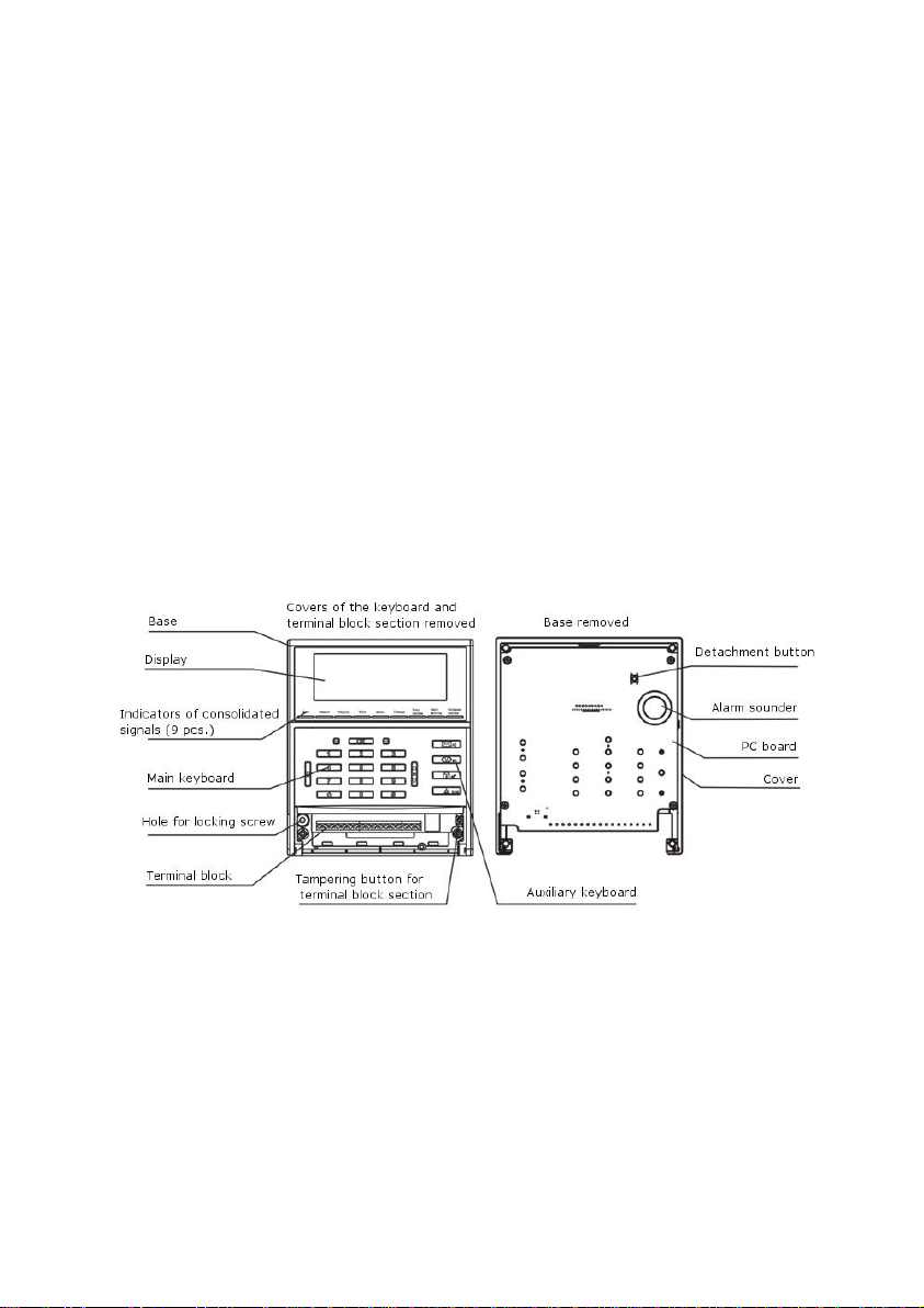
4 Structure
4.1 The keypad consists of a base, a keyboard with a closing cover, a display,
indicators of consolidated signals, a printed circuit board (PCB) with radioelements, a
terminal compartment with a removable cover.
4.2 Tampering of the terminal compartment is controlled by a tamper switch.
6
Page 7
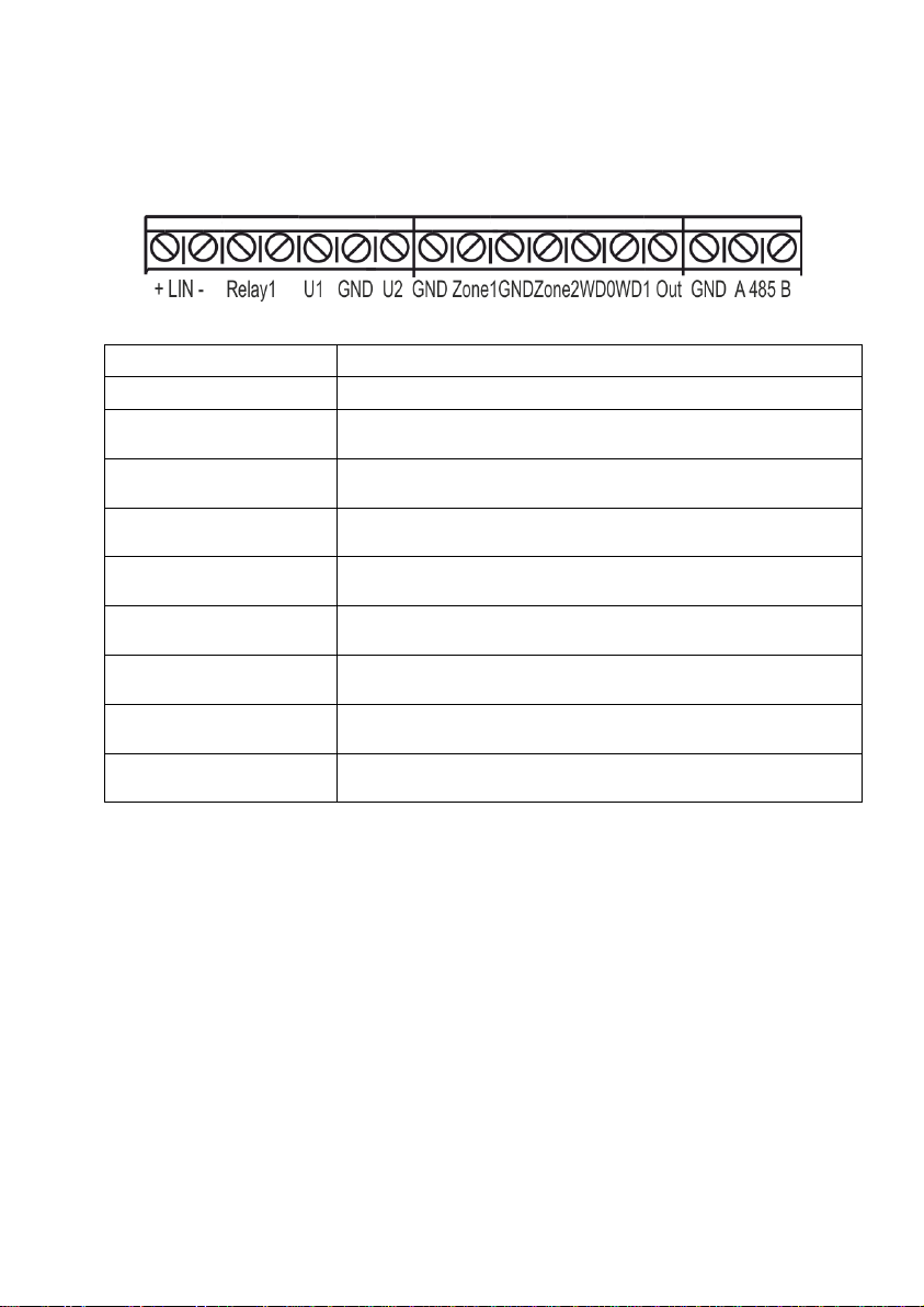
Terminals
Application
+LIN-
Not applicable
Relay1
System relay output (operation mode is set by MSS
Astra Pro)
U1, GND
Connection of main power source (input)
U2, GND
Connection of auxiliary power source (input)
Zone1, GND
Control of consolidated signal “Failure” from power
sources (input)
GND, Zone2
Connection of intrusion detectors (input)
WD0, WD1
Connection of TM key reader (input)
Out, GND
Connection of LCD for TM key reader (output)
485A, 485B
Interface RS-485
4.3 On the rear side of the PCB are installed a built-in buzzer and a detachment
button, which controls detachment of the keypad from the mounting surface.
4.4 The keypad is provided with USB interface for communication with a computer
whenever change of SW needed.
4.5 The PCB contains a terminal block (see application in Table 1):
Table 1
7
Page 8
Keys
Functions
ОК
Complete entering data in a field or a command confirmation
С
Quit to main operating mode or previous menu
#
Enter special functions (create masks, allowing bypass of
faulty event source etc.)
▼, ▲
Moving up and down menu, view events in the log.
«–» right from ОК
Move right to view the second part of notification on the
display
«–» left from ОК
Move left to return the main part of notification on the display
0 … 9
Enter PIN codes and other digital values
ОК «PIN» ОК
Authorization or entering the Engineer/ Technician/
Operator/ User menu according to access level provided by
PIN code
«PIN» ОК
Direct control over arming/disarming of the partitions
according to access level provided by PIN code
«PIN» # ОК
Arming according to access level provided by PIN code
(if authorized), excluding some zones (faulty ES)
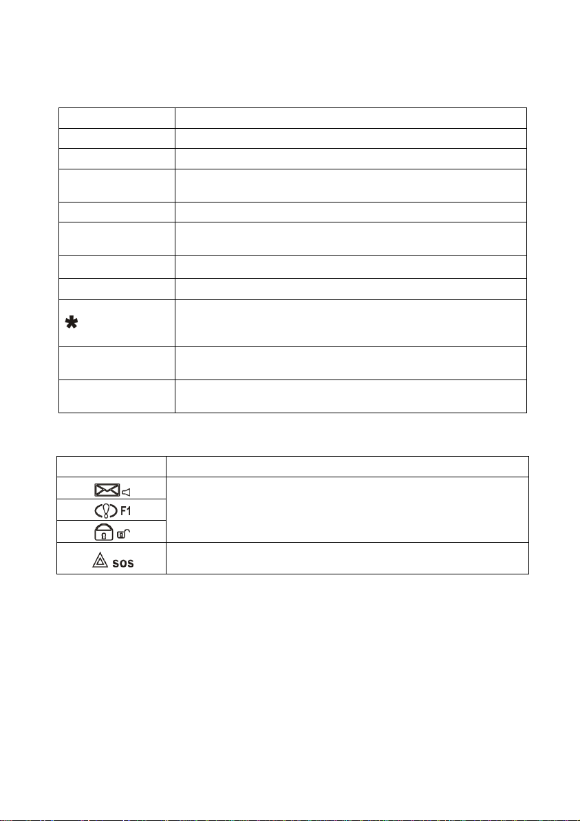
Keys
Functions
Not applicable in present keypad, CP and MSS Astra Pro
Panic button
(Must be adjusted with MSS Astra Pro for use)
5 Key Functions
5.1 Main Keyboard
5.2 Auxiliary Keyboard
8
Page 9

6 Main Features and Functions
6.1 Control
6.1.1 The keypad represents an access terminal and provides functions permitted
by a PIN code which has been entered in the process of authorization or direct
control.
Authorization means access to a menu item which corresponds to the access level
authorized by PIN code.
Direct control means entering a PIN code for direct control over arming/ disarming
of partitions.
Authorization and direct control shall be performed according the rules in the Table in
Paragraph 5.1.
6.1.2 When computer monitoring of the system with Monitors of MSS Astra Pro is
used:
in the process of access to the system from the keypad with application of
Engineer PIN code, the working Monitors of Operators and Technicians
display a notification that a highest-level access session is open in the
System Core, and operation of the Monitors is suspended. After running
time of active Engineer mode expires, the keypad sends a command for
automatic termination of Engineer session in the Core, and the Monitors
display correspondent notifications;
in the process of access to the system from the keypad with application of
Operator PIN codes, Technician or User PIN codes, operational capability of
Technicians or Operators are not affected on their Monitors.
6.1.3 Direct control over arming/disarming of partitions according to levels of
authorization provided by PIN codes shall be available only for Users.
The control shall be performed with indication of statuses of the partitions, which are
specified in the entered PIN code immediately after a command output report is sent
or C key is pressed.
6.1.4 The keypad provides for connection of TM key reader. Control over
arming/disarming of partitions with TM keys is done according to authorizations
provided from MSS Astra Pro.
9
Page 10

1
Fire 7 Exit delay
2
Fire danger
8
Sabotage
3
Alarm
9
Critical failure
4
Violation
10
Service required
5
Test
11
Standby mode
6
Entry delay
Standby mode
Alarm Part. 002
In progress
Alarm PIR0003/1
6.2 Informational Capacity
6.2.1 In standby mode in the absence of any events or failures, after any key
(except numerical ones and key) has been pressed, the display will show:
In such a case only display functions, the keypad itself doesn’t communicate with CP.
If any event or failure occurs, the first one of these will be displayed, e.g:
The keys «–» located on the right and left side from ОК key, enable transfer to 2nd
screen for detailed information – address, e.g:
Information is displayed according to the following priorities with status is displayed:
To view next event on the display, respond in any acceptable way to the previous one:
disarm and eliminate the cause of violation, remedy sabotage or failure.
6.2.2 The keypad provides information from CP using temporary storage buffer.
Whenever it is necessary to add some information (e.g. when viewing events in the
log), the keypad will automatically connect with CP with the following notice:
10
Page 11

Indicator
Notification
Indication
POW
«Power normal»
Constant green light
«Switching to backup
power »
Blinking green light 1 time/s
«Backup power
failure»
Blinking yellow light 2 times/s
«Power failure»
Blinking yellow light 1 time/s
FAILURE
«Normal»
Constant green light
«Failure»
Blinking yellow light 1 time/s
«Sabotage»
Blinking yellow light 2 times/s
VIOLATION
Not applicable
Not lit
«Not ready»/«Ready»
Blinking green light 1 time per 2 s
Done
The transfer will be ended with the message:
whereupon it will be possible to continue working with the keypad.
6.2.3 Built-in Buzzer (BZ) on the keypad shall be setup as a system virtual output.
When any events occur in partitions assigned to BZ, there will be generated an
acoustical signal. The BZ shall be activated within a period corresponding to
regulatory documents:
within 10 min or until manually switched off for “intrusion” and
“technological” partitions;
until manually switched off for “fire” partitions.
6.2.4 Indicators of consolidated signals show generalized current status of
system partitions, corresponding to specific indicators on the keypad (Table 2).
Assigning a partition to a specific indicator is done during the system setup from
Setup module included into MSS Astra Pro.
Table 2
11
Page 12

Indicator
Notification
Indication
«Armed»
Constant green light
«Violation»,
«Alarm»
Blinking red light 2 times/s
TEST
«Power-up test»
Constant yellow light within 20 s
«Standby mode»
Not lit
«Test»
Blinking alternatively green/ yellow
light 4 times/s within test time
FIRE
DANGER
Not applicable
Not lit
«Not ready»
Blinking green light 1 time per 2 s
«Normal»
Constant green light
«Fire danger»
Blinking red light 1 time/s
FIRE
Not applicable
Not lit
«Not ready»
Blinking green light 1 time in 2 s
«Normal»
Constant green light
«Fire»
Constant red light
SYSTEM
START
Not applicable with present keypad, CP and MSS Astra Pro
SYSTEMS
ON
SYSTEM
STOP
6.2.5 The design of the keypad doesn’t envisage any “hot keys” for prompt viewing
of partitions of the system. Information provided only within authorizations of entered
PIN code.
12
Page 13

User menu
Operator menu
Technician menu
Engineer menu
1. Part. status
1.Part. control
1. Part. control
1. Sys. dev. status
1.View all
2.Alert. control
2. Alert. control
2. Wls dev. status
2. By part. number
1.Start alerting
1. Start alerting
3. Part. status
2.Part. control
2.Cancel alerting
2. Cancel alert.
1. View all
3.VA status
3. VA status
2. By part. number
3.Part. status
3.Part. status
4. Failures
1. View all
1. View all
1. By part. number
2. By part. number
2. By part. number
2.Sabotage
4.Failures
4. Failures
3.Failure
1. By part. number
1. By part. number
4. Service req.
2.Sabotage
2.Sabotage
5.All 3.Failure
3.Failure
5.Event log
4. Service req.
4. Service req.
1.Failures
Operator menu
7 Keypad Menu
7.1 Menu Structure
User authorization within access level provided by entered PIN code is made by
pressing the following keys ОК «PIN» ОК. Thereafter the display will show
corresponding information.
For example, for the Operator:
Navigation trough menu items is by pressing the keys ▼, ▲, or by entering the
required number of a command (see menu on Page 13,14).
General menu structure:
13
Page 14

User menu
Operator menu
Technician menu
Engineer menu
5.All
5.All
2.Alarms
5. Event log
5. Event log
3.W/o arm/disarm
1.Failures
1.Failures
4. By part. number
2.Alarms
2.Alarms
5.All
3.W/o arm/disarm
3.W/o arm/disarm
6.Keypad
4. By part. number
4. By part. number
1. Settings
5. All
5.All
1.Contrast
6. Wls. dev. status
2.Key volume
7. Sys. dev. status
3. Act. mode time
8. Keypad
4.Backlight
1. Settings
5.Delete
1.Contrast
2.Тest
2.Key volume
1. Test Keybd.
3. Act. mode time
2. Test backlight
4.Backlight
3. Test BZ
2. FW version
4.Status test
3. FW update
3.FW version
9. Date setting
4.FW update
10. Time setting
7. Date setting
8. Time setting
To confirm your choice press ОК; to abandon your choice and return to previous
menu item press С.
7.2 User Menu
7.2.1 To enter User menu, key in PIN code, assigned for each User of the system,
authorized to perform control using the keypad.
7.2.2 Information in first sub-item «1.View all» of the item «1.Part. status» will be
displayed depending from authorities granted by the entered PIN code.
14
Page 15

View all
A S
009
002
Select partition
Р002 Armed
IP 0004 Р:008
tampering
Example statuses of two partitions that fall within authorities of the entered PIN code:
The second line shows statuses designated by letters,
the third/fourth line shows numbers of partitions.
One display is able to show statuses of up to 16 partitions. If authorities provided by
PIN code cover more partitions, you may use keys «–» located on the right and left
side from ОК key.
Interpretation of partition statuses:
«a» - partition is armed
«R» - partition is ready to be armed (partition disarmed)
«N» - partition is not ready to be armed (partition disarmed)
«F» - partition is in «fire» status
«A» - partition is in «alarm» status
«D» - partition is in «Fire danger» status
«S» - partition is in «sabotage» status
7.2.3 After entering menu sub-item «2. By part. number», the display will show
partition number and information about the status of selected partition, e.g.:
The required partition may be selected using keys ▼, ▲, or numerical ones. After
ОК is pressed, you may inquire about failures in the selected partition and see them
listed on the display.
Browsing using the keys ▼, ▲ results in succession of view screens:
Here:
«IP» – type of device which sends information about failure,
«0004» – ES address (0004 – number in the list of hardwired units, 0 –
number of the device detection channel; in the given example:
own failure status),
«Р:008» – partition number,
«tampering» – event type.
15
Page 16

Part. control
Р007 Ready
Р007 Ready
1. Arm
MC 0011/1 Р: 007
alarm
7.2.4 The menu item «2. Part. control» enables to view a list of partitions and their
current statuses.
Browsing using the keys ▼, ▲ results in succession of view screens:
In case the partition is ready to be armed:
By pressing # you may update data.
In case the partition is not ready to be armed, the reasons may be displayed through
pressing #. Browsing of view screens is done by pressing ▼, ▲:
Here:
«MC» – type of device sending information, which confers the status
“not ready” to the partition,
«0011/1» – ES address (0011 – number in the list of wireless or hardwired
units, 1 – number of the device detection channel; in the given
example: built-in magnet-steered contact),
«Р:007» – partition number,
«alarm» – event type.
In case the partition is not ready to be armed, you should eliminate causes.
In exceptional cases, arming for partitions, which are not ready, is permitted with
bypass, if it is authorized by settings for the partition. Bypass procedure is described
in “Partition” of the manual to MSS Astra Pro.
By pressing ОК on the selected partition, you bring out view screen:
By pressing keys ▼, ▲ in the second line you may choose the necessary operation
for the partition. A list of possible operations is determined by control tactics
authorized by settings for User PIN code entered in the process of authorization.
16
Page 17

Not completed
Done
Part. control
Р007 Armed #
HE 0003/1 Р:007
[bypass] failure
A full list of possible operations:
1. Arm
2. Arm with bypass
3. Disarm
4. Re-arm
Your choice is to be confirmed by pressing ОК, thereafter the keypad will send a
command to CP, which will be executed and confirmed or not confirmed in view
screens:
Execution may be rejected in case of sending a command, conflicting with the status of a
partition, e.g. you try to arm a partition, which is not ready.
The command «2. Arm with bypass» (equivalent is PIN code with additional # in
case of direct control, see 5.1) enables to ignore causes if it is allowed by settings of
the partition. If conditions of bypass are executed, the partition, which is not ready to
be armed will be armed with the following notification
After the notification appears, by pressing # you may see detailed conditions of
arming as view screens, which may be browsed by pressing ▼, ▲:
Here:
«HE» – type of device sending information, which confers the status
“not ready” to the partition
«0003/1» – ES address (0003 – number in the list of hardwired (or wireless)
units, 1 – number of the device detection channel; in the given
example AL № 1 of hardwired receiver)
«Р:007» – partition number
«[bypass]» – operation
«failure» – event type.
Attention!
Arming with bypass results in partial loss of control over the protected
facilities and it is not recommended to use it as a constant remedy!
17
Page 18

Alert. control
1. Start alerting
Alert. control
2. Cancel alert.
Alert. control
3. VA status
Start alerting
Area 01 Msg. 01
Cancel alert.
2. By area number
VA status
S D
08
03
By area number
Area 01
7.3 Operator Menu
7.3.1 After authorization is done (Paragraph 7.1) the displayed information in menu
items «1.Part. control» and «3.Part. status» will be generated depending upon
authorizations for the entered PIN code. Other steps are similar to those described
for the User menu.
7.3.2 The menu item «2.Alert. control» enables to send or cancel voice alerting,
and to view alerting status.
Possibilities for sending, cancellation and viewing will be built depending upon
authorizations established for the PIN code, which has been entered.
Examples of screens:
press ОК press ОК press ОК
select an
option and
press ОК
Areas are selected from a list, which may be browsed by pressing ▼, ▲, or
numerical keys.
Messages are selected in a similar way, but without dependence upon authorities in
the full range from 1 to 8.
The screen for viewing statuses schematically shows 2 areas, designated by PIN
code authorities.
18
Page 19

IP 0004
tampering
The following statuses are used for viewing:
«S» - alerting stopped
«D» - delay before alerting start
«A» - alerting is ON.
ATTENTION!
According to requirements, a minimum time delay for starting alerting makes
30 seconds. This time is intended for cancellation of alerting, when obvious
false response is detected. In practice, applied time delay makes minimum 1
minute.
When cancelling alerting, you should take into account additional time,
required for exchange of information between the keypad and the central CP
during authorization, selecting a menu item and sending a cancellation
command. This time makes on average about 15 seconds and must be
considered when you set up time of delay.
7.3.3 The menu item «4. Failures» enables to view failures using filters for your
convenience:
«1. By part. number» – failures, service required and sabotage.
«2.Sabotage» – tampering and detachment from mounting
surface.
«3.Failures» – all critical failures excluding tampering and
detachment.
«4.Service required» – non-critical failures, which require maintenance of
the devices, but not leading to “not ready” statuses
of the partitions (e.g. reduction of main power
supply).
If you select the filter «1. By part. number», the information will be displayed as
described in 7.2.3.
Activation of the filter «2.Sabotage» results in display of a list, which browsing by
pressing ▼, ▲ will lead to succession of view screens:
When you select the filters «3.Failures» and «4. Service required» the information
will be displayed as in «2.Sabotage».
19
Page 20

IP 0004
BPS low voltage
MC 0034
No connection
Event 2181 Failure
system
Examples of screens:
or
Upon cancellation of filtration in the menu item «4.Failures» you may select the last
item «5.All», which will activate a general list of failures, which may be browsed by
pressing ▼, ▲.
7.3.4 The present FW version is not restricted by authorizations for viewing the
event log.
The menu item «5.Event log» enables viewing events stored in CP memory using
filters:
«1.Failures» – critical failures.
«2.Alarms» – only «alarms» / «fires» / «violations» in the armed
partitions.
«3.W/o arm/disarm» – all the events in all categories except “arming” and
“disarming”.
«4. By part. number» – all the events in the selected partition.
«5.All» – all the events in the system without filters, including
When any of the filters is chosen, the keypad addresses CP with an inquiry according
to the type of the chosen filter and adds last 10 events selected using the filter to the
temporary storage buffer. Inquiry to CP is similar to described in 6.2.2.
When the filter «1.Failures» is selected, the information is displayed from the last in
time event (having the largest number in the current working cycle of CP from
10000).
Example of screen:
Here in the example:
«Event 2181» – event number (from 10000).
«Failure» – interpretation of event.
«system» – involved area.
information about activities of Engineer
20
Page 21

No connect. MC0034
23rd Jan 11:51:11
Event 2176 Alarm
partition
Event2180 Sabotage
system
Event2172 Not armed
partition
Alarm PIR0016
23rd Jan 10:03:59
Tampered MC0034
23rd Jan 11:47:08 a.m
User 7 PIN003
23rd Jan 10:03:04 a.m
Browsing is done by pressing ▼, ▲.
After the last event has been displayed from the temporary storage buffer and
activation of the next one by Operator by pressing ▼, the keypad automatically
inquires CP for the next group of earlier events, and further repeats the inquiry, if
required.
Similarly, the events will be transferred from CP on the display of the keypad by
pressing ▲, but in the reverse order.
You may see details of the event by pressing «–» on the right side from ОК.
Example of screen:
Here in the example:
«No connect.» – event
«MC0034» – type of the device and ES address (0034 – number in the list of
radio units)
«23rd Jan» – date of event according to calendar of CP
«11:51:11 a.m.» – time of event according to CP clock
By pressing «–» on the left side from ОК you may return to the previous screen.
By selecting any other filter you slightly change the list, which is generally similarly
operated.
Examples:
press «–»
to the right of ОК
21
Page 22

RTR
Astra-Z-8745 versions A/B Repeater/Router
Astra-Z-8845 versions A/B Repeater/Router
Zone-GND
PIR
Astra-Z-5145 versions A/B/P PIR motion detectors
Zone-GND
AC
Astra-Z-6145 acoustic glass break detectors
Zone-GND
VBR
Astra-Z-6245 vibration detector
MC
Astra-Z-3345 magnetic contact door opening detectors
Zone-GND
TRZ
Astra-Z-3345 door opening detectors in universal transmitter mode
Zone-GND
KF
Astra-Z-3245 remote control key fob
WRU
Astra-Z-8245 wireless relay unit
FSD
Astra-Z-4245 fire smoke detector
FHD
Astra-Z-4345 fire heat detector
FCP
Astra-Z-4545 fire call point
WLD
Astra-Z-3645 water leak detector
LSA
Astra-Z-2345 light and sound alerter (siren)
FLA
Astra-Z-2745 fire light alerter (EXIT sign)
FVA
Astra-Z-2945 fire voice alerter
WKP
Astra-Z-8145 Pro wireless control keypad
АC 0020 S8
ТМP NOR NOR NOR
RTR 0008 S6
ТSТ MPF
7.4 Technician Menu
7.4.1 After authorization (Par. 7.1) is complete, displayed information in the menu
items «1. Part. control», «2.Alert. control», «3.Part. status», «4.Failures» will be
generated depending upon authorizations for the entered PIN code.
All other steps, including viewing the log in the menu item «5. Event log» are similar
to those described in 7.2 and 7.3 for User and Operator menu.
7.4.2 The menu item «6.Wls dev. status» enables to view statuses of wireless
devices (WD) registered in CP and displayed on view screens by browsing using the
keys ▼, ▲:
The 1st position in the first line shows the type of WD. Some of WD may have
inputs of detection channels Zone-GND. The present FW version for CP and the
keypad uses the following entitlements:
22
Page 23

1st
position
TMP
WD tampered or detached from the mounting
surface
For
all WD except RTR
(8745)
NOR
WD closed, not detached
2nd
position
NOR
generalized «normal» status, no violations on
main detection channel and no failures
For
all WD except RTR
(8745)
ТSТ
Positive test result
For
all WD except KF and
WKP
PNC
Key pressed ! on KF and on WKP
For KF and WKP
ALM
Violation in the main detection channel
For RTR (8845), PIR,
AC, MC, TRZ, WLD,
VBR, WRU
FR
Violation in the main detection channel
For FSD, FHD, FCP
FLR
wireless device general failure
For
RTR (8845), PIR, AC,
MC, TRZ, WLD, LSA,
FLA, FVA, VBR, WRU
3rd
position
NOR
no violations on auxiliary detection channel
For
ED, АC, MAC, TRA
ALM
violation on auxiliary detection channel
4th
position
NOR
power supply normal
For
RTR (8745 B and 8845
B), PIR, AC, MC, TRZ,
WLD, KF, VBR, WRU
FLR
Power supply voltage below normal, battery
discharged
NOR
power supply normal
For
WKP, RTR (8745 A and
8845 A), FSD, FHD,
FCP, LSA, FLA, and
FVA
MPF
Main power supply voltage below normal, main
battery discharge, absence of main power supply
voltage or main battery
BPF
BAT voltage below normal, backup battery
discharge, absence of BAT or backup battery
The 2nd position displays the number in the list of wireless devices included into the
system.
The 3rd position describes the level of radio signal in the scale from «S1» to «S8» for
wireless units included into the system Astra-Zitadel or absence of signal - NS.
On the second line, the 4 items show abbreviations with the following meanings:
23
Page 24

FLR
BAT voltage below normal , backup battery
discharge at absence of main power supply or
main battery and vice versa
CP
Central Control Panel Astra-8945 Pro
HKP
Keypad Astra-814 Pro
RVZ
Embedded wireless receiver
WE
Wireless extender Astra-Z WE
HE
Hardwired extender Astra-713
IP
Indication panels Astra-863 A/AE/B/BE
RU
Relay unit Astra-823
GSM
Module Astra-GSM
PSTN
Module Astra-PSTN
LAN
Module Astra-LAN
CP 0001 SGL
NOR NOR
RU 0035 SGL
ТМP NOR CUT NOR
HE 0034 SGL
TMP_R_fDFAE NOR
7.4.3 The menu item «7.Sys. dev. status» enables to view statuses of hardwired
devices registered in CP by browsing using the keys ▼, ▲.
Examples:
The 1st position in the first line shows the type of the device included into the
systems in all types of hardwired communication interfaces (UART, RS-485, LIN).
In the present FW version for CP:
The 2nd position on the first line shows the number of the device in the system
device list.
The 3rd position indicates data transfer: SGL (signal) or NS (no signal).
24
Page 25

1st
position
TMP
Device tampered
For
CP, WE, HE, RU, and
HKP
NOR
Device closed
NOR
GSM communicator enables remote control
For GSM
LCK
Remote control blocked
4th
position
NOR
Power supply normal
For HE, RU, GSM
FLR
Power supply voltage below normal
NOR
Power supply normal
For CP, WE, IP,
HKP
MPF
Main power supply below normal or missing
BPF
Backup power supply below normal or missing
FLR
backup power supply below normal when the
main power supply is missing, or vice versa
For
RU
in the 2nd pos.
for Output1
NOR
controlled circuit of the relay output is normal
CUT
controlled circuit of the relay output is in open-circuit
status
in the 3rd pos.
for Output2
SC
short circuit in the controlled circuit of the relay output
For
RVZ, WE
in the 2nd pos.
RF jam.
RF jamming
NOR
radio channel normal
For
PSTN
in the 2nd pos.
No line
no connection to the telephone line
NOR
connection to the telephone line
For
GSM
in the 2nd pos.
for SIM 1
SХХ
signal level according to scale from S00 to S16 in the
presence of communication with the base station;
in the absence of communication error number is
displayed
The second line displays in 4 positions letter abbreviations standing for:
Note: If a device is not initialized, there will appear the notification: “Initialization…”;
For different types of devices, the 2nd and 3rd items may display various types of
information:
25
Page 26

in the 3rd pos.
for SIM 2
ErХ
communication error with base station.
0 … 9 is error code (see interpretation in the table on
Page 27)
For LAN
in the 2nd and
3rd pos.
CAB:CON
cable connected
CAB:DISC
cable disconnected
For HE
in the 2nd and
3rd pos.
(8 possible
Values)
«_»
AL not assigned in ES
R
Status «Normal» and ready to be armed for all types of
AL (except «fire heat double-event»).
AL resistance within 3,0 to 5,0 kOhm.
For AL of «fire heat double-event» type means that only
one detector is in fire status
f
Status «Failure» .
Resistance ranges for ALs of different types are various.
For details see manual integrated into Setup Module of
MSS Astra Pro software
D
AL resistance within 1,5 to 3,0 kOhm.
For AL of «fire combined double-event» type means that
only one detector is in fire status.
For AL of «fire heat double-event» type indicates
«Normal» status and readiness to be armed
F
Status «Fire»:
- AL resistance within 5,0 to 12 kOhm for all AL of
«fire…» types;
- AL resistance within 0 to 1,5 kOhm for «fire combined
double-event» type;
- AL resistance within 1,5 to 3,0 kOhm for «fire
combined single-event» type
A or E
Status «Alarm» or «Violation» for “intrusion” and
“technological” AL correspondingly.
Resistance of AL between 0 and 3,0 кOhm or from 5,0
кOhm till open-circuit status.
For HKP
in the 2nd pos.
PNC
Key « » pressed (Panic)
NOR
Status «Normal»
in the 3rd pos.
ALM
Status «Violation» for AL2 («Zone2»)
NOR
Status «Normal» for AL2 («Zone2»)
26
Page 27

0
roaming registration
1
no communication with GSM module (inner interface in the device)
2
unknown error (undeclared by GSM module)
3
SIM card absent
4
SIM card read error
5
PIN code providing access to SIM card required
6
unlocking of SIM card required
7
no GSM service
8
search network
9
registration of network rejected
Detailed description of resistance ranges of AL of different types and their
assignment to partitions of the correspondent types is to be found in the Operation
Manual integrated into the Setup Module of MSS Astra Pro.
ATTENTION!
Full coincidence of letter symbols with standard statuses of AL are observed in
two types of AL: “intrusion” and “fire combined with single event”. You should
be attentive when viewing statuses of other types of AL.
Codes of errors occurring when communication established between GSM
communicator and base station:
7.4.4 The item menu «8.HKP» allows to change the display contrast, the volume of
sound of pressed keys, the duration of the active mode, and to show the current
software version on the display.
All manipulations are intuitive and require no further description.
7.4.5 The item «FW update» («8.HKP»/ «3.FW update») enables to switch the
keypad to FW update mode. After selection of the mode is confirmed by pressing ОК,
it is necessary to connect the keypad to the computer using a USB cable, start the
FW Update Module from MSS Astra Pro and change the FW. Changing of FW
doesn’t affect any settings in the keypad.
7.4.6 The menu items «9. Date Setting» and «10. Time Setting».
Conditions of use:
It is possible to adjust time from the keypad menu, when CP operates without
computer control. It is recommended to check and adjust the date manually
27
Page 28

Not completed
Forbidden
minimum once in 3 months.
In case, when the central CP connected to computer with working System
Core from MSS Astra Pro, and there is communication between the System
Core and CP, it is impossible to adjust date and time. CP synchronizes
calendar and clock with the computer calendar and clock through the System
Core. In case time divergence is more than 1 minute, it is recorded to the
event log.
At an attempt to adjust the time via keypad the following message is displayed.
7.5 Engineer Menu
7.5.1 Access to Engineer Menu for the keypad, which hasn’t been registered in
CP is provided with application of default PIN (password) «1 2 3 4 5 6». Hereby
only «6.HKP» menu item will be available.
The menu item enables to test the keypad before commissioning (see 7.5.6), view
the current version of the FW installed in the keypad, and, if necessary, to update
FW. Steps are similar to those described for Technician Menu (see 7.4.5). You may
change FW without preliminary registration in CP. It is possible as well to adjust
display contrast, duration of active mode, and the volume of sound of pressed keys.
7.5.2 After the keypad has been registered in CP, authorization is made with
application of Engineer PIN code (Par. 7.1), assigned from MSS Astra Pro. The
information in the menu items «1.Sys.dev.status», «2.Wls.dev.status» will be
displayed in similar way to the described in 7.4.2, 7.4.3 for Technician Menu.
7.5.3 The information to be displayed in the menu items «3.Part. status»,
«4.Failure» will be generated according to authorizations provided for Engineer PIN
code. Engineer has supreme status in the system, but he is prohibited to take control
over system partitions (arming/disarming), that is why system control tactics
configuration in the task “Identifiers” in Setup Module from MSS Astra Pro is not
possible.
Nevertheless, in order to provide viewing capabilities, there must be binding to
partitions. Otherwise, to provide status view of partitions, they must have
assignments. Otherwise, the following messages are displayed:
28
Page 29

Part. status
1. View all
Part. status
2.By part. number
Failures
1. By part. number
View all
No available part.
Select partition
No available part.
Select partition
No available part.
123456789*0#
Status test
ТМP PNC NOR NOR
7.5.4 Operations in the menu items «5.Event log», «6.HKP», «7.Date setting» and
«8.Time setting» will be performed in similar way to the described earlier in the
Operator and Technician Menus (see 7.3.4, 7.4.4, 7.4.5).
7.5.5 The item «Deletion» («6.HKP»/«1.Settings»/«5.Deletion») enables to delete
(unregister) the keypad, which has been earlier registered in CP. This must be done
before registration in other CP.
7.5.6 The sub-item «2.Test» of the menu item «6.Unit» serves for keypad general
testing before it`s commissioning, prior to registering in wireless network.
«1. Test keyboard» after pressing ОК the following view screen will
appear:
where each pressing of keys on the keyboard will
result in darkening (in the example keys «1», «2»,
«3», «4», «5» are pressed).
«2. Test backlight» press ОK button to display the backlighting mode
screen. Use ▼, ▲ to change settings interactively.
«3. Test buzzer» press ОK button to display the built-in buzzer mode
screen. Use ▼, ▲ to change settings interactively.
29
Page 30

In the 1st position
TMP
terminal section of the keypad tampered
or detachment button released
(detachment from mounting surface)
NOR
terminal section closed, and the
detachment button pressed (the keypad
fixed on mounting surface)
In the 2nd position for «SOS»
button status
PNC
«SOS» key pressed
NOR
«SOS» key not pressed
In the 3rd position for
intrusion-type AL status
NOR
AL2 (terminal Zone2) normal
ALM
AL2 (terminal Zone2) violated
In the 4th position for main
and backup power sources
NOR
both power supply sources are normal,
AL1 (ZONE1) normal
MPF
main power supply voltage is below
normal, AL1 (ZONE1) and backup power
supply voltage normal
BPF
backup power supply voltage is below
normal, AL1 (ZONE1) and main power
supply voltage normal
FLR
AL1 (ZONE1) is violated and/or voltage of
both power supplies are below normal
On the second line, the 4 items show abbreviations with the following meanings:
ATTENTION!
After registration of the keypad in CP the sub-item «2.Test» will be inaccessible (in
the menu structure on Page 14 marked in grey).
30
Page 31

Where:
Rter – terminal resistor in the alarm
loop 3,9 kOhm;
E1 – power supply unit operability
output with NC contacts;
E2 - power supply unit operability
output with NO contacts;
E3 - intrusion detector with NC
contacts;
E4 - intrusion detector with NO
contacts;
PS1 – main power supply unit;
PS2 – backup power supply unit;
К1 – reader Touch memory or other
technology issuing Dallas 1990A
code.
Astra-814 Pro
CSP
PS1
PS2
Rter
Rter
8 Pre-Starting Procedure. Registration and
Installation
After being transported in conditions which differ from operating ones, the keypad
must be left unpacked under operating temperature for minimum 4 hours.
8.1 Wiring
1. Open the keyboard cover.
2. Loosen two screws on the terminal block section with a
screwdriver, and remove the cover.
3. Insert wires through the hole in the bottom base and
connect them following the scheme:
31
Page 32

Fail.
No communicat. with CP
Attention!
No registration
4. As soon as the keypad is powered on, the test mode is activated, which is
intended to test operability of the electronic circuit of the keypad. Maximum test time
is 20 s.
Entering the test mode will be accompanied by sound activated for 1s with a
frequency 4 times/s. During test all indicators except TEST indicator blink with a
frequency 2 times/s, changing their colors (red-green). The indicator ТEST
illuminates steady yellow.
After test is completed, the display of the keypad will show: “Attention! No
registration”.
5. The Engineer Menu shall be entered using default PIN code (password) «1 2 3
4 5 6» ( ОК 1 2 3 4 5 6 ОК). Test the keypad following instructions from
«2.Тest» sub-item of the «6.HKP» menu item (see 7.5.6).
6. Replace the cover of the terminal block section and tighten the screws. If
necessary, close the cover of the keyboard.
8.2 HKP Registration Procedure
Registration of the keypad in the system is to be done following the method for
registration of the units, described in the Operation Manual integrated into Setup
Module of MSS Astra Pro.
The operation will not be performed, if the keypad has already been registered in CP. In
this case, the display of the keypad will show the message:
If this occurs, it is necessary to delete registration parameters through Engineer Menu
of the keypad (see 7.5.5). This will result in displaying the message
32
Page 33

8.3 Installation
1) Mark the selected surface using the mounting layout on the last page of this
Operation Manual.
2) Tighten the screws included into the delivery package.
3) Open the keyboard cover, loosen 2 screws on the terminal block section, remove
the cover of the terminal block section.
4) Hang the keypad, make a mark for a locking screw (see drawing on Page 6).
5) Remove the keypad, drill a hole for the locking screw.
6) Hang the keypad, and secure it with the locking screw.
7) Close the cover of the terminal block section, tighten 2 screws.
8) If necessary, close the cover of the keyboard.
9 Maintenance
To ensure fault-free operation of the keypad, it is recommended to test it and perform
technical maintenance as follows:
- check operability of the keypad at least once a month,
- check the case of the keypad for possible damages and clean it at least
once a month;
- check whether the keypad is reliably attached, and check the condition of
external wires, and of contacts at least once in 3 months.
10 Labeling
The label on the case of the keypad specifies:
- the trademark of the manufacturer;
- abbreviated designation of the keypad;
- firmware version;
- month and year of manufacture;
- conformance mark (if there is any certificate of conformance);
- barcode which backups the text information.
33
Page 34

11 Recycling
The keypad does not pose any threat to life and health of people, as well as to the
environment. After the expiry of its service life period, the keypad shall be disposed of
without special precautions in respect to the environment.
12 EC Conformity Declarations
This product is in conformity with the provisions of:
LVD 73/23/EEC+93/68/EEC
EMC 89/336/EEC
EN 61000-6-3:2005 Electromagnetic compatibility (EMC) - Part 6-3: Generic
standards - Emission standard for residential, commercial and light-industrial
environments.
EN 50130-4:1995 + A1:1998 + A2:2003 + Corrig. 2003 Alarm systems - Part 4:
Electromagnetic compatibility - Product family standard: Immunity requirements for
components of fire, intruder and social alarm systems.
EN 60950-1: 2001+A11:2004+Corrig.2004 Safety of information technology equipment
13 Manufacturer’s Warranties
13.1 The Quality Management System certified for compliance with GOST ISO 9001.
13.2 The manufacturer guarantees that the keypad will comply to technical
requirements, provided that the consumers adhere to specified technical conditions
of transportation, recommendations on storage and use.
13.3 The warranted shelf life is 5 years 6 months from the manufacturing date.
13.4 The warranted service life is 5 years from the commissioning date, but not more
than 5 years 6 months from manufacturing date.
13.5 The manufacturer must repair or replace the keypad within the warranty period.
13.6 The warranty does not become effective in the following cases:
- failure to comply with this Operation Manual;
- mechanic damage of the keypad;
- if the keypad is improperly repaired by anyone other than the manufacturer.
13.7 The warranty covers only the keypad. All other equipment of other
manufacturers used with the keypad is subject to other manufacturer’s warranties.
In no case shall the manufacturer be liable for any death, physical injury or
property damage, or any other accidental or intentional loss based on claim
that the keypad failed to perform its functions.
34
Page 35

MOUNTING LAYOUT
35
Page 36

Sales:
Controlex GmbH
Warranty service and
technical support:
ТЕКО-TD
Philosophenweg 31-33
47051 Duisburg, Germany
Phone: +49 (0) 203 / 393 91 188
Fax: +49 (0) 203 / 393 91 189
GSM: +49 (0) 178 / 218 48 22
E-mail: info@controlex.eu
Web: www.controlex.eu
Prospekt Pobedy str. 19
420138 Kazan, Russia
Phone: +7 (843) 261-55-75
Fax: +7 (843) 261-58-08
E-mail: info@teko.biz
support@teko.biz
Web: www.teko.biz Made in Russia
Version 814Pro-v1_1
36
 Loading...