

Page 1
Astra-Z-6145
Wireless Surface Acoustic Glass Break Detector
Operating Manual
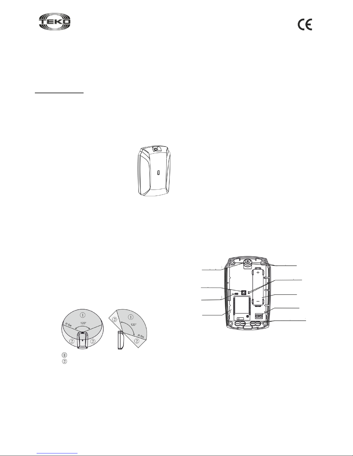
Fig. 1
This manual is intended for studying principles of operation,
correct use, operating conditions and maintenance of the Wireless Surface Acoustic Glass Break Detector Astra-Z-6145
(hereinafter “detector”) (Fig. 1).
The manufacturer reserves the right to make alteration regarding refinement of the product without prior notification. All
changes will be imported into new edition of the operation
manual.
List of Abbreviations
Astra-Zitadel System – the on-site Wireless Intrusion / Fire
Detection and Alarming System Astra-Zitadel;
Astra-Zitadel System Control Panel – Astra-Z-812M, Astra-Z-
8945 ver.A, Astra-8945 Pro or Astra-812 Pro Control Panel (with
connected Astra-Z Wireless Extender);
MSS Astra-Z – Astra-Z Monitoring Software Suite;
MSS Astra Pro: Astra Pro Monitoring Software Suite;
LT – Laser Tester Astra-942;
Battery – power supply battery.
1 Function
1.1 The detector detects the breaking of
glass in closed glassed rooms, generates the
alarm notification and sends the notification to
the Control Panel of the Astra-Zitadel System
via radio channel.
Types of glass:
- conventional and protected with a polymer
film, thickness from 2,5 mm to 8 mm;
- armored glass, thickness from 5,5 mm and
6 mm;
- figure glass, thickness from 4 mm to 7 mm;
- laminated construction glass, thickness from 6 mm to 8 mm;
- tempered glass, thickness from 4 mm to 6 mm space is at
least 0,1 m2 (length of one of the sides is at least 0,3 m).
1.2 The detector supports connection of external hard-wired
detectors with NO/NC outputs of «dry contact»-type.
Note: Zone-GND Input does not have current control.
1.3 The detector is powered by lithium-thionyl- chloride bat-
tery of AA size with voltage of 3.6 V (included in the delivery
set).
2 Operating Principle
2.1 The principle of operating is based on the registration of
breaking glass by means of analysis of an acoustic signal in
the sound frequency range. The microphone is a sensor. An
electric signal proceeds from the microphone comes to microcontroller, which forms an alarm notification in accordance with
specified operation algorithm.
2.2 Schematics of the detection zone are shown in Fig. 2.
Fig. 2
3 Specifications
Technical Parameters of Acoustic Channel
Two operating frequency bands:
- first (high), kHz ............................................................. 4 to 6
- second (low), Hz .................................................... 100 to 200
Detector coverage range, m, min ............................................... 6
Detection area angle, degrees, min .................................... 120
Technical Parameters of Radio Channel
Operating frequency range, MHz ...................... 2400 to 2483.5
Number of active channels with 5 MHz increment ................ 16
Channel width, MHz ................................................................ 2
Wireless coverage range, line-of-sight, m, min ................... 300
General Technical Parameters
Detector current consumption, mA, max:
- radio module OFF ............................................................ 0.13
- radio module ON .............................................................. 105
Battery replacement indication threshold, V .................... 2.7
-0.2
Power supply voltage lower threshold (deactivating
threshold retaining battery discharge indication), V ............. 2.1
Overall dimensions, mm, max ............................. 101.56332
Weight (without battery), kg, max ...................................... 0.07
Average battery service life, years, min ..................................... 2
Operating Conditions
Temperature range, °С ................................ from -20 up to +50
Relative air humidity, % .............................. up to 95 at + 35 °С
no moisture condensation
4 Delivery Set
Wireless Surface Acoustic
Glass Break Detector Astra-Z-6145 ................................... 1 pcs.
Battery ER14505 ............................................................... 1 pcs.
Screw 2.9×25 ..................................................................... 4 pcs.
Dowel 5х25 ........................................................................ 4 pcs.
Operating Manual ............................................................ 1 copy.
5 Structure
Fig. 3
5.1 Structurally, the detector is designed as a unit consisting of a
base and a removable cover. The unit houses a printed circuit
board with radio elements (Fig. 3).
5.2 Mounted on PCB is a Zone-GND terminal block for con-
necting external emergency detectors (gas leak, water leak,
etc.). Wire length is 3 m max.
5.3 Mounted on PCB is a Tamper Switch (S1button), which
results in the «Tampering» notification when the cover is removed.
5.4 Mounted on PCB are LEDs: red (for monitoring the detec-
tor’s operability) and white (for wireless network status supervision).
Confident detection area
Probable detection area
(in case of positive testing with a steel ball)
Cover removed
Battery installed
Mounting
holes
Microphone
LED indicators
Tamper
switch
Battery
Reg plug
Screw
terminal block
PCB
Wire insertion
holes
Page 2
Rev. 6145-v3_1_en
2
6 Information Capacity
Table 1 – Notification – Detector indicators and control panel
Type of
notification
Red
indicator
White
indicator
Control
panel
Detector
standby mode
start
Lights up once for
1 to 20 s after
power is up
Not lit
−
Norm
Not lit
+
Alarm
Lights up once
for 2 s when the
protected glass
is being broken
Not lit
+
Zone-GND
input violation
Lights up once
for 0.2 s
Not lit
+
Low-frequency
(LF) interference
in the acoustic
channel
Lights up for 0.5 s
with 1 s pause for
as long as interference is present
Not lit
−
High-frequency
(HF) interference
in the acoustic
channel
Blinks twice with
1 s pause for as
long as interference is present
Not lit
−
Powering up
Not lit
Any
Power supply
failure
Blinks 3 times
every 25 s
Not lit
+
Tampering/
Tampering
restored
Lights up once for
0.2 s
Not lit
+
Network
search
Not lit
Blinks with
frequency of 5
Hz for 1 to 60
s
−
No network
Not lit
Blinks 2 times
every 25 s
−
Radio module
failure
Not lit
Blinks 3 times
every 25 s
+
“+” – the notification is given, “–” – the notification is not given
Notes
1 If «Power failure» notification appears, change the battery
within three weeks.
2 Indication of notification on HF and LF interference, “Viola-
tion”, “Network search” is initiated for 10 to 250 minutes by a
command from the control panel or MSS interface and then
automatically ceases to save energy.
7 Operating Modes
The detector operating modes are set via radio upon a command from the control panel in accordance with appropriate
Astra-Zitadel System Control Panel`s Operating Manual *.
Upon a command from Control Panel it is possible to:
1) set detector sensitivity to normal or high;
2) switch on indication for 10 to 250 min;
3) switch Zone-GND terminals channel on/off;
4) set RF supervision time;
5) set operating channel.
The normal sensitivity mode is used when the distance to
protected glass with thickness of more than 3 mm is less than
3 meters.
8 Pre-Starting Procedure
8.1 After transportation in conditions differing from those of
operation, the detector must be kept unpacked for at least 4
hours in the operating conditions.
8.2 Running Detector. Battery Replacement
WARNING! Lithium-thionyl-chloride batteries have an effect of
«passivation» to provide the possibility of long-term storage. To
provide battery normal operation after long-term storage, hold
an «activation» procedure.
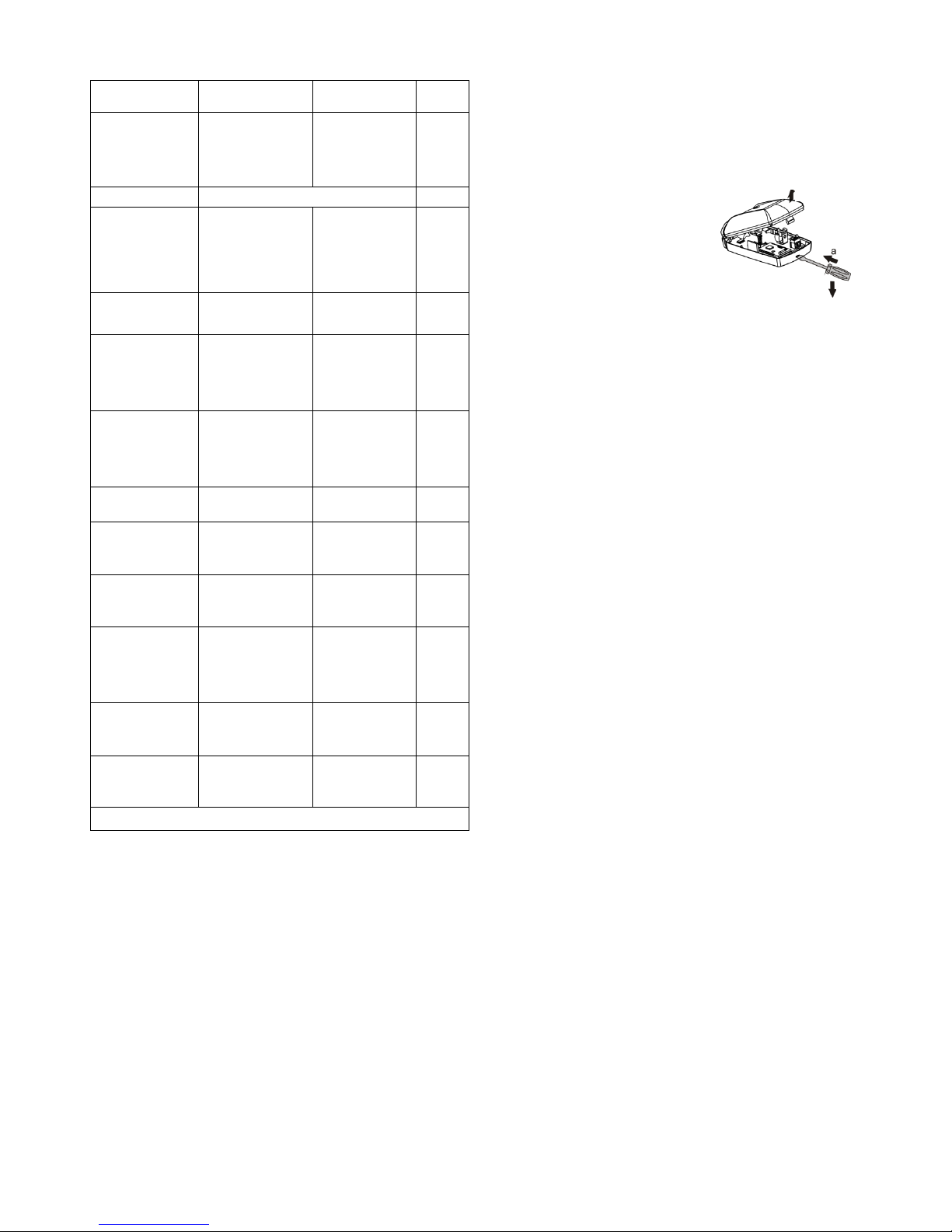
Step-1
Push cover lock from base slot.
Remove cover
Step-2
Insert the battery (To replace battery remove the old one and
after no less than 10 sec install the new one).
The LED will light up one time for 1 to 20 seconds - battery
activation and check period.
If after 20 seconds the red LED flashes with a triple blink
every 25 seconds, re-activate the battery by removing, and
after at least 10 seconds reinserting it.
As a last resort, use a piece of wire to close the battery’s
positive and negative poles for 2-3 seconds.
WARNING! Closing the poles for more than 3 seconds leads
to battery discharge
8.3 Registering the Detector in the Wireless Network
Detector registration is required for detector identification in the
wireless network in which it shall operate.
Step-1
According to Astra-Zitadel System Control Panel`s Operating
Manual * perform the following procedure:
1) Install Software ** (MSS Astra-Z, Pconf-Z or MSS Astra
Pro) intended for configuring Control Panel.
2) Create wireless network
Step-2
Perform p. 8.2
Step-3
Switch the control panel to Wireless device registration
mode by the method described in the appropriate Control
Panel Operating manual *
Step-4
Initiate detector registration procedure by one of 2 methods:
а) using the LT (step-5);
b) using the Reg plug and the Tamper switch (step-6)
WARNING!
Avoid to initiate registration procedure on several detectors simultaneously
Step-5
Initiating Detector Registration Procedure Using LT:
- press the lower LT button and wait until the beam appears;
- shine the laser beam on the detector indicator;
- illuminate the indicator for 1 s.
The detector`s red LED lights up for 2 seconds, then the
detector switches to wireless network search mode and the
white LED blinks at a frequency of 5 Hz
b
c
Page 3

Rev. 6145-v3_1_en
3
Step-6
Initiating Detector Registration
Using Reg Plug and Tamper
Switch:
1) Using a screwdriver, shortly
(for 1-2 s) close the Reg plug
The “Waiting for detector registration in
the network” mode switches ON for 60 s
2) Shortly press the Tamper switch on the detector.
The detector switches to the wireless network search mode, and
its white indicator blinks with frequency of 5 Hz.
Step-7
Verify registration procedure:
Once registration procedure
completed successfully, the
abbreviated name of detector «AC»
appears on the screen or «ACxxx
registered» notification appears on the
control panel`s screen Assemble the detector.
In case registration procedure failed, the control panel
screen displays «Registration time expired» notification. In
this case, repeat the registration procedure, i.e. perform operations 3 and 5 or 3 and 6.
Step-8
After successful registration of the detector, for long term
storage before its installation, it is allowed to switch the
detector OFF by removing the battery or installing a soft
isolator.
When power is supplied, there is no need to re-register the detector in the same wireless network if it was not intentionally
removed from the network through software or control panel`s
menu.
8.4 Deleting Detector from Wireless Network
Deletion the detector from wireless network is
performed using Software ** or through Control Panel`s
menu.
When deleting detector from wireless network, Control Panel
transmits notification about deletion to detector within two
periods of RF supervision time. After receiving the
notification detector issues "No network" notification.
To speed up the deletion procedure:
- remove detector`s cover
- shortly close Reg plug
- press and hold down tamper switch for 8-10 sec.
The detector issues "No network" notification to LED and is
available for registration
9 Installation
9.1 Selecting a Location
9.1.1 Recommended height of installation on a wall and fur-
thermost distance from secured glass
9.1.2 Installation options
9.1.3 Non-recommended installation places
9.1.4 It is prohibited the detector in a room with high levels of
sound interference.
9.1.5 For the period of protection it is recommended to close
doors, windows of secured space, switch off ventilators and
other possible sound interference sources.
9.1.6 Make sure that the entire space of secured glass is
covered by detection area. It is not allowed to drape the detector with curtains etc. Otherwise sensitivity can be limited.
9.2 Installation Procedure
Step-1
Push cover lock from base slot.
Remove cover
Step-2
Unbend hooks on the
base. Remove PCB
Step-3
If Zone-GND input is used for
connection of external emergency detectors, remove
blanks from the selected wire
insertion holes
Hook
Page 4

Rev. 6145-v3_1_en
4
Step-4
Press out blanks of selected
mounting holes
Make markings on the wall at
an appropriate height by using
the applied base.
Attach the base
Step-5
Replace PCB matching
PCB slots with guides on
the base. Press on PCB
until it clicks in position
Step-6
Lead wires from external emergency detectors
through the selected hole on the detector base.
Connect wires to the terminal block.
Step-7
Set a detector operating mode in accordance with appropriate
Control Panel Operating Manual *
Step-8
Carry out testing of the detector by knocking on the furthermost part of the secured glass. Please, don´t break secured
glass:
1) place a test steel ball with diameter of 21-22 mm and
weight of 32-48 g, suspended from a 35 cm thread, right by
the glass surface without touching it;
2) deflect the ball by 3070 (Table 3) in the plane perpendicu-
lar to the glass surface without changing the suspension point
and not allowing the thread to go slack. Release the ball.
The test operator shall not obstruct the detector during the
impact;
3) during the test impact the detector red LED lights up for 2
s, and an “Alarm” notification shall be sent to the control
panel.
Table 3 – Angle of steel ball inclination
Glass thickness, mm
Less
than
3
34
45
56
67
More
than
7
Angle of inclination for
glass conventional and
protected with a polymer film, deg
45
50
55
60
65
70
Angle of inclination for all
other glass types, refer to
p.1.1.deg
30
35
40
45
50
55
Step-9
Replace the detector cover (until it
clicks)
9.3 To provide for reliable operation of the alarm system it is
recommended to test and maintain the detector.
The detector shall be tested at least once a week using the
test ball.
Perform technical maintenance at least once a month as
follows:
- inspect integrity of the detector body,
- inspect reliability of mounting,
- clean the detector from any dirt accumulated.
10 Labeling
The following data are shown on the label glued to the body:
- manufacturer trademark;
- detector abbreviated designation;
- firmware version;
- month and year of manufacture (last two digits);
- conformity mark (if the conformity certificate is available);
- bar code, duplicating textual data.
11 EC Conformity Declarations
This product is in conformity with the provisions of:
R&TTE Directive 1999/5/EC, Article 10.5;
EN 60950: 2001 Safety of information technology equipment;
EN 50371 Generic standard to demonstrate the compliance of lowpower electronic and electrical apparatuses with the basic restrictions
related to human exposure to electromagnetic fields (10 MHz - 300
GHz) – General public;
EN 301489-17 V1.1.1 (09-2000) Electromagnetic Compatibility and
radio spectrum Matters (ERM); Electromagnetic Compatibility (EMC)
standard for radio equipment and services; Part 17: Specific conditions for wideband data Hiperlan equipment;
EN 300220-1 V1.3.1 (2000-09) Electromagnetic compatibility and
Radio spectrum Matters (ERM); Short range devices; Technical characteristics and test methods for radio equipment to be used in the 25
MHz to 1 000 MHz frequency range with power levels ranging up to
500 mW; Part 1: Parameters intended for regulatory purposes.
Construction of the detector provides for protection class IP41.
12 Recycling
12.1 Detector is not a danger to life, human health and the environ-
ment. On expiry of its lifetime recycling is done without taking special
measures to protect the environment.
12.2 Recycling of battery cells should be done by delivering used cells
to a trading organization, service centre, manufacturer, or to an organization accepting used batteries.
13 Manufacturer Warranties
13.1 Quality Management System meets provisions of ISO 9001-2011.
13.2 The manufacturer guarantees the compliance of the detector to
specifications on condition that user observes required conditions of
transportation, storage, installation and operation.
13.3 The storage warranty period is 5 years and 6 months from the
date of manufacture.
13.4 The operating warranty period is 5 years from the date of com-
missioning, but not more than 5 years and 6 months from the date of
manufacture.
13.5 The manufacturer shall repair or replace a faulty detector during
the warranty period.
13.6 The warranty becomes void if:
- the user does not follow guidelines of the operating manual;
- the detector is mechanically damaged;
- the detector is repaired by a party other than the Manufacturer.
13.7 The warranty covers the detector only. All equipment manufac-
tured by other parties and used with the detector, including batteries, is
covered by its respective warranty.
The manufacturer bears no responsibility for death, injury, property damage or other incidental or premeditated loss based on
user's statement that the device failed to implement its functions.
* Available for free downloading from www.controlex.eu
and/or integrated with configuring software.
** Available for free downloading from www.controlex.eu.
Sales:
Controlex GmbH
Warranty service and
technical support:
ТЕКО-TD
Philosophenweg 31-33
47051 Duisburg, Germany
Phone: +49 (0) 203 / 393 91 188
Fax: +49 (0) 203 / 393 91 189
GSM: +49 (0) 178 / 218 48 22
E-mail: info@controlex.eu
Web: www.controlex.eu
Prospekt Pobedy str. 19
420138 Kazan, Russia
Phone: +7 (843) 261-55-75
Fax: +7 (843) 261-58-08
E-mail: info@teko.biz
support@teko.biz
Web: www.teko.biz
Made in Russia
Directed at protected
glass
cm
Glass
 Loading...