

Page 1
Astra-Z-4545
Wireless Manual Fire Alarm Call Point
Operation Manual
This operation manual is intended for studying the operating
principles, proper use, storage, and maintenance of the
Wireless Manual Fire Alarm Call Point Astra-Z-4545
(hereinafter referred to as a detector) (Figure 1).
List of Abbreviations:
Astra-Zitadel System: Astra-Zitadel on-site Wireless Intrusion
/ Fire Detection and Alarming System;
Astra-Zitadel System Control Panel: Astra-Z-812M, Astra-Z8945 ver.A, Astra-8945 Pro or Astra-812 Pro Control Panel
(with connected Astra-Z Wireless Extender);
LT: Astra-942 Laser Tester;
MSS Astra-Z: Astra-Z Monitoring Software Suite;
MSS Astra Pro: Astra Pro Monitoring Software Suite.
1 Function
1.1 The detector is designed for manual
activation of a fire alarm by pressing the
driving element, forming «Fire»
notifications, and transmitting them to the
Astra-Zitadel System Control Panel via
radio.
1.2 Power is supplied to the detector
from one or two lithium-thionyl-chloride
batteries (primary and secondary), size
AA, voltage 3.6 V.
2 Operating Principle
The detector is activated by pressing the actuator – indestructible plate. After being pressed the plate locks in the pushed
position. Microprocessor forms «Fire» notification in accordance with pre-set algorithm.
The detector is returned to standby mode by returning the
actuator to an initial state with a key-pusher.
3 Specification
Technical Parameters of Radio Channel
Operating frequency range, MHz .................. 2 400 to 2 483. 5
Number of operating channels at 5 MHz intervals ................ 16
Channel width, MHz ............................................................... 2
Wireless coverage range, line-of-sight, m, min ................... 300
General Technical Parameters
Current consumption, mA, max:
- with radio module OFF .................................................... 0.04
- with radio module ON ....................................................... 105
Battery replacement
indication threshold, V ......................................................... 2.6
Power supply voltage lower threshold (programmed
deactivation threshold retaining
battery discharge indication), V ........................................... 2.1
Overall dimensions, mm, max ................................. 110x94x47
Weight (without battery), kg, max ...................................... 0.17
Primary battery average lifetime, years, min .......................... 3
Primary+Secondary batteries set
average lifetime, years, min .................................................... 5
Operating Conditions
Temperature range, °C ................................ from -30 up to +55
Relative air humidity, % ............................... up to 93 at +40 °C
without moisture condensation
4 Delivery Set
Astra-Z-4545 ................................................................... 1 pcs.
Mortise key (large) ........................................................... 1 pcs.
Key-pusher (small) .......................................................... 1 pcs.
Battery ............................................................................. 2 pcs.
Screw 3.9×32 .................................................................. 2 pcs.
Dowel 6×30 ..................................................................... 2 pcs.
Operation Manual ........................................................... 1 copy
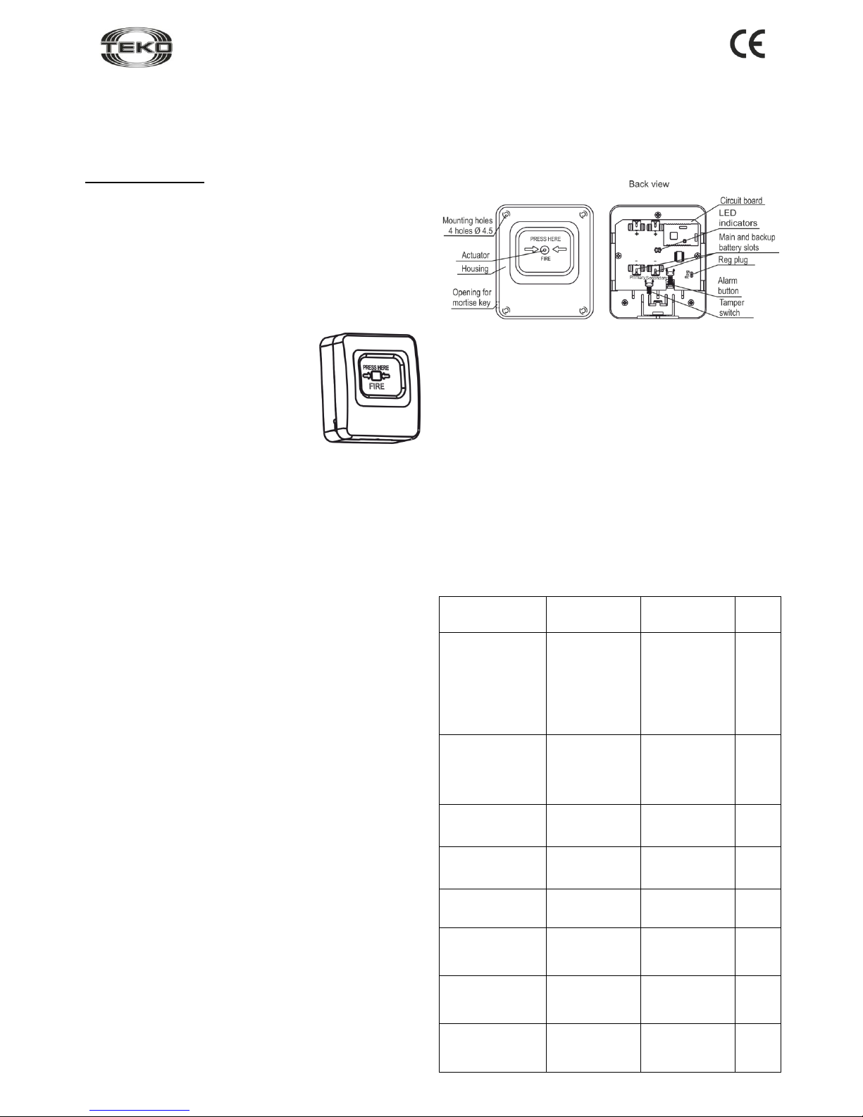
5 Structure
5.1 The detector is designed as a block consisting of a
removable cover and a base, made of high-impact plastic
(Figure 2).
Figure 2
5.2 Mounted inside the cover is a printed circuit board (PCB)
with radio elements and slots for the primary and secondary
batteries. The recessed part of the cover also contains an
actuator with an inscription that clearly marks the place and
direction to be pressed
5.3 The upper section of the recessed part contains white or
yellow shutter, which emerges when the actuator is pressed.
5.4 Mounted on PCB is a tamper switch (S1button), which
results in the «Tampering» notification when the cover is
removed.
5.5 Mounted on PCB are LEDs for the detector’s operability
supervision.
6 Notifications
Table 1: Notifications processed by LEDs and Control Panel (or
MSS interface)
Notification
Type
Red
LED
White
LED
Panel
Standby
mode start
Lights up one
time for 1 to
40 seconds
after detector
powering up
Not lit
−
Normal
Blinks one
time per
(60±5)
seconds for
0,2 seconds
Not lit
+
Fire
Lights up
one time for
10 seconds
Not lit
+
Tampering
Lights up one
time for 0.2
seconds
Not lit
+
Powering up
Not lit
Any
+
Primary battery
failure
Not lit
Any
+
Secondary
battery failure*
Not lit
Any
+
Power failure
Triple blink
every 25
seconds
Not lit
+
Base removed
Figure 1
Page 2
Rev. 4545-v3_1_en
2
Notification
Type
Red
LED
White
LED
Panel
Network search
Not lit
Blinks with
frequency of
5Hz for 1 to 60
seconds
−
No network
Not lit
Double blink
every 25
seconds
−
Radio module
failure
Not lit
Triple blink
every 25
seconds
+
+: notification issued
–: notification not issued
*: with secondary battery installed
Notes
1 The «Power failure» notification is processed by the red LED
if both batteries are discharged or if one of the batteries is
missing and the second battery is discharged.
2 If «Primary battery failure» notification appears, replace
the battery within two months.
7 Pre-starting Procedure
7.1 After transportation in conditions differing from those of
operation, keep the detector unpacked for 4 hours in the
expected operating conditions.
7.2 Switching Detector On, Replacing Batteries
WARNING! Lithium-thionyl-chloride batteries have an effect of
«passivation» to provide the possibility of long-term storage. To
provide battery normal operation after long-term storage, hold
an «activation» procedure.
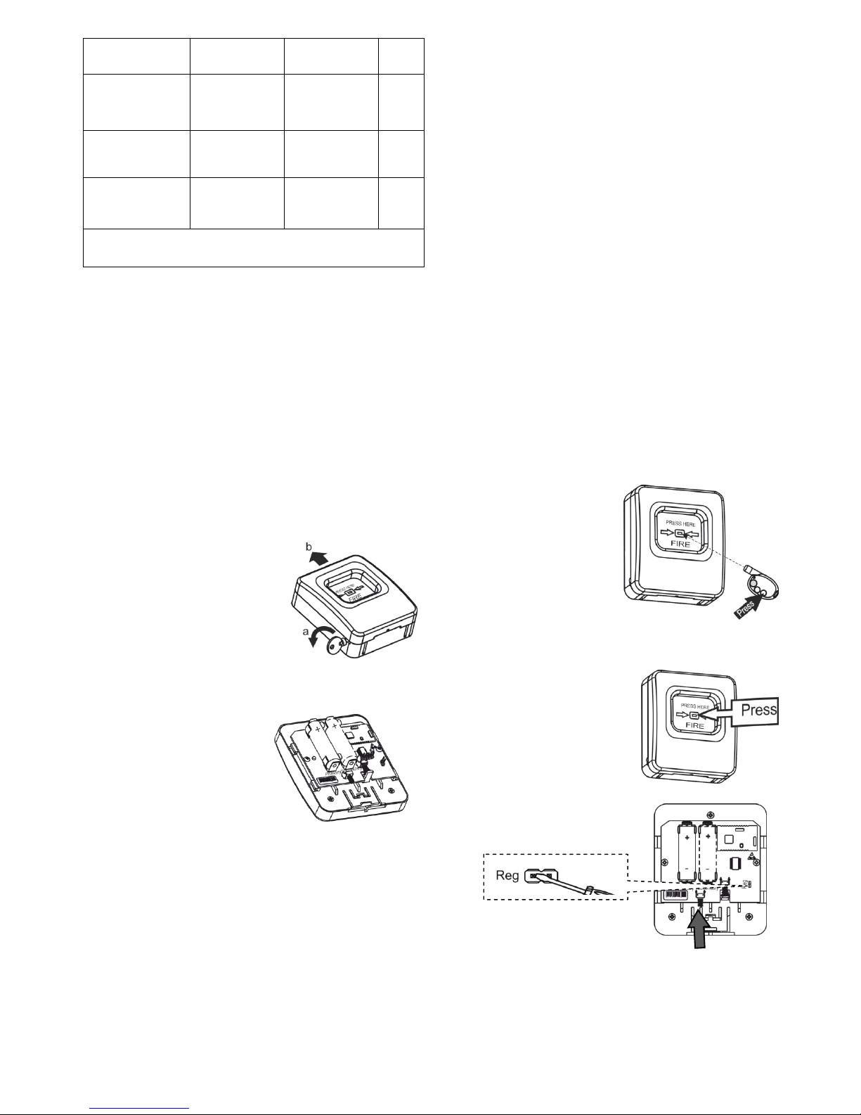
Step-1
Insert the mortise key into the
slotted opening on the left side of
the detector.
Turn the key counterclockwise
while simultaneously shifting the
cover upwards.
Separate the cover from the base.
Step-2
When using one battery to switch the detector ON, insert the
main battery (Primary).
When using two batteries, it is
recommended to insert the
backup battery (Secondary)
first, and then the main battery
(Primary). The backup battery
can be inserted up to 1 minute
after inserting the main battery.
To replace the battery, remove
the old battery, wait at least
30 seconds, and insert the new one.
The LED lights up one time for 1 to 40 seconds – the battery
activation and checking period.
If after 40 seconds the red LED flashes with a triple blink
every 25 seconds, activate the battery by removing it, waiting
at least 30 seconds, and reinserting it.
Warning! If two batteries have been inserted, replace
both batteries.
7.3 Registering the Detector in the Wireless
Network
Detector registration is required for detector identification within
the wireless network in which it is supposed to operate.
Step-1
According to Astra-Zitadel System Control Panel`s
Operating Manual * perform the following procedure:
1) Install Software ** (MSS Astra-Z, Pconf-Z or MSS Astra
Pro) intended for configuring Control Panel.
2) Create wireless network
Step-2
Perform par.7.2
Step-3
Switch the control panel to Wireless device registration
mode by the method described in the appropriate Control
Panel Operating manual *
Step-4
Initiate detector registration by one of 2 methods:
a) using the LT (step-5);
b) using the Reg plug and the tamper switch (step-6)
WARNING!
Avoid to initiate registration procedure on several
detectors simultaneously
Step-5
Initiating Detector Registration Using the LT:
- Press the lower button on the LT and hold until a beam
appears.
- Direct the laser beam at the
detector LED.
- Irradiate the LED for 1
second.
The detector red LED lights
up for 2 seconds, and then
the detector switches to
wireless network search
mode and the white LED
lights up at a frequency of 5
Hz.
Step-6
Initiating Detector Registration
Using the Reg Plug and
Tamper Switch:
1) Press the detector actuator to
release the microswitch
compressed spring.
2) Shortly (for 1-2 seconds)
connect the Reg plug with a
screwdriver.
The detector switches to
registration in wireless network
mode for 60 seconds.
3) Within 60 seconds, shortly press the tamper switch on
the detector. The detector switches to wireless network
search mode and the white LED lights up at a frequency of
5 Hz.
Page 3

Rev. 4545-v3_1_en
3
Step-7
Verify registration procedure:
Once registration procedure completed successfully,
the abbreviated name of
detector «FCP» appears on
the screen or «FCPxxx
registered» notification
appears on the control panel`s
screen.
Assemble the detector:
- Press the detector cover
against the base and align the
slots.
- Shift the cover down until the latch clicks.
If registration procedure failed, the control panel screen
displays «Registration time expired» notification.
In this case, repeat the registration procedure, i.e. execute
steps 3 and 5 or 3 and 6.
Step-8
After successful registration of the detector, for long term
storage before its installation, it is allowed to switch the
detector OFF by removing the battery or installing a soft
isolator.
When power is supplied, there is no need to re-register the
detector in the same wireless network if it was not
intentionally removed from the network through software or
control panel`s menu.
7.4 Deleting Detector from Wireless Network
Deletion the detector from wireless network is performed
using Software ** or through Control Panel`s menu.
When deleting detector from wireless network, Control Panel
transmits notification about deletion to detector within two
periods of RF supervision time. After receiving the
notification detector issues "No network" notification.
To speed up the deletion procedure:
- remove detector`s cover
- shortly close Reg plug
- press and hold down tamper switch for 8-10 sec.
The detector issues "No network" notification to LED and is
available for registration.
8 Installation
8.1 Install the detector in an accessible location.
8.2 Installation Procedure
Step-1
Insert the mortise key into the slotted
opening on the left side of the
detector.
Turn the key counterclockwise while
simultaneously shifting the cover
upwards.
Separate the cover from the base.
Step-2
Mark the selected installation site for
the applied base.
Connect the jack.
Mounting holes
Step-3
Press the detector cover against
the base and align the slots. Shift
the cover down until the latch
clicks.
Step-4
Verify detector operability:
1) Press the actuator. In the upper section of the recessed
part of the cover, a white shutter emerges, indicating that the
detector has switched to the alarm position.
The actuator’s red LED lights up for 10 seconds and the
«Fire» notification is transmitted to the control panel (MSS
interface).
2) Return the detector to the standby position:
- Insert the key-pusher firmly into the opening on the bottom
edge of the detector (until the actuator is released).
- Remove the key.
3) Activate test mode (for
communication channel
supervision):
- Press the upper button on the
LT.
- Direct the laser beam at the
detector LED.
- Irradiate the LED for 1 second.
After 5 seconds, make sure «Fire» notification appears on the
LED – the red LED lights up for 10 seconds. A «Test fire»
event is recorded in the control panel (or MSS interface) event
log.
8.3 To ensure the alarm system reliable operation, testing
and maintenance of the detector is recommended.
Testing should be carried out least once a week according to
procedure described in p.8.2 step 4.
Perform technical maintenance at least once in 3 months as
follows:
- Inspect the detector cover integrity;
- Ensure reliability of its mounting;
- Purge the detector from contamination.
9 Labeling
The following information is marked on the label attached to the
detector housing:
- manufacturer trademark;
- abbreviated detector designation;
- firmware version;
- month and year (last two digits) of manufacture;
- conformity mark (if the conformity certificate is available);
- bar-code that duplicates textual information.
10 EC Conformity Declarations
This product is in conformity with the provisions of:
R&TTE Directive 1999/5/EC, Article 10.5;
EN 60950: 2001 Safety of information technology equipment;
EN 50371 Generic standard to demonstrate the compliance of lowpower electronic and electrical apparatuses with the basic restrictions
related to human exposure to electromagnetic fields (10 MHz - 300
GHz) – General public;
EN 301489-17 V1.1.1 (09-2000) Electromagnetic Compatibility and
radio spectrum Matters (ERM); Electromagnetic Compatibility (EMC)
standard for radio equipment and services; Part 17: Specific conditions for wideband data Hiperlan equipment;
EN 300220-1 V1.3.1 (2000-09) Electromagnetic compatibility and
Radio spectrum Matters (ERM); Short range devices; Technical characteristics and test methods for radio equipment to be used in the 25
MHz to 1 000 MHz frequency range with power levels ranging up to
500 mWt; Part 1: Parameters intended for regulatory purposes.
Construction of the detector provides for protection class IP41.
11 Recycling
11.1 Detector is not a danger to life, human health and the
environment. On expiry of its lifetime recycling is done without taking
special measures to protect the environment.
11.2 Recycling of battery cells should be done by delivering used cells
to a trading organization, service centre, manufacturer, or to an
organization accepting used batteries.
Laser
tester
Page 4

Rev. 4545-v3_1_en
4
12 Warranty Terms
12.1 Quality Management System meets provisions of ISO 9001-2011
12.2 The manufacturer guarantees the compliance of the detector to
specifications on condition that user observes required conditions of
transportation, storage, installation and operation.
12.3 The storage warranty period is 5 years and 6 months from the
date of manufacture.
12.4 The operating warranty period is 5 years from the startup date,
but not more than 5 years and 6 months from the date of manufacture.
12.5 The manufacturer guarantees replacement or repair of the
product during the warranty period.
12.6 The warranty doesn’t come into effect in the following cases:
- not adherence to the operating manual;
- mechanical damage to the detector;
- repair of the detector by any third-party service except for the
manufacturer.
12.7 The warranty applies to the detector only. All equipment from
other manufacturers used with the detector, including batteries, is
subject to its own warranty terms.
The manufacturer bears no responsibility for death, injury,
property damage or other incidental or premeditated loss based
on user's statement that the device failed to implement its
functions.
* Available for free downloading from www.controlex.eu
and/or integrated with configuring software.
** Available for free downloading from www.controlex.eu.
Sales:
Controlex GmbH
Warranty service and
technical support:
ТЕКО-TD
Philosophenweg 31-33
47051 Duisburg, Germany
Phone: +49 (0) 203 / 393 91 188
Fax: +49 (0) 203 / 393 91 189
GSM: +49 (0) 178 / 218 48 22
E-mail: info@controlex.eu
Web: www.controlex.eu
Prospekt Pobedy str. 19
420138 Kazan, Russia
Phone: +7 (843) 261-55-75
Fax: +7 (843) 261-58-08
E-mail: info@teko.biz
support@teko.biz
Web: www.teko.biz
Made in Russia
 Loading...