

Page 1
Astra-Z-4245
Wireless Optic-Electronic Fire Smoke Detector
Operation Manual
This operation manual is intended for studying the operating
principles, proper use, storage, and maintenance of the
Wireless Optic-Electronic Fire Smoke Detector Astra-Z-4245
(hereinafter referred to as detector) (Figure 1).
The manufacturer reserves the right to make changes to
improve the detector without prior notification. All changes will
be included in the new revision of the operation manual.
List of Abbreviations:
Astra-Zitadel System: Astra-Zitadel on-site wireless intrusion /
fire detection and alarm system;
Astra-Zitadel System Control Panel: Astra-Z-812M, Astra-Z8945 ver.A, Astra-8945 Pro or Astra-812 Pro Control Panel
(with connected Astra-Z Wireless Extender);
LT: Laser Tester Astra-942;
MSS Astra-Z: Astra-Z Monitoring Software Suite;
MSS Astra Pro: Astra Pro Monitoring Software Suite.
1 Function
1.1 The detector is intended for detecting
fire accompanied by smoke, forming and
transmitting «Fire» notification to the AstraZitadel system control panel via radio.
1.2 Power is supplied to the detector from
one or two lithium-thionyl-chloride batteries
(primary and secondary), size AA, voltage
3,6 V.
2 Operating Principle
The detector’s operating principle is based on registering
infrared radiation (hereinafter IR) that is reflected from smoke
particles in a smoke chamber by a photodetector. Further the
electric signal formed by the photodetector is amplified and
sent to microcontroller in order to analyze the smoke density
value. The microprocessor forms smoke density value and
«Fire» notification in accordance with specified operating
algorithm.
3 Specification
Detector sensitivity, dB/m ........................................ 0.05 to 0.2
Response time, s, max ......................................................... 10
Detection area, m2, max ..................................................... 110
Installation height, m, max .................................................... 10
Technical Parameters of Radio Channel
Operating frequency range, MHz .................. 2 400 to 2 483. 5
Number of operating channels at 5 MHz intervals ................ 16
Channel width, MHz ............................................................... 2
Wireless coverage range, line-of-sight, m, min ................... 300
General Technical Parameters
Current consumption, mA, max:
- with radio module OFF .................................................... 0.05
- with radio module ON ....................................................... 105
Battery replacement
indication threshold, V ......................................................... 2.6
Power supply voltage lower threshold (programmed
deactivation threshold retaining
battery discharge indication), V ........................................... 2.1
Technical readiness time, s, max ......................................... 40
Standby mode recovery time, s, max ....................................... 60
Overall dimensions, mm, max:
- diameter ........................................................................... 106
- height ................................................................................. 60
Weight (without battery), kg, max ...................................... 0.13
Primary battery average life time, year, min ........................... 3
Primary+Secondary batteries average life time, year, min ..... 5
Operating Conditions
Temperature range, °C ..................................... from -30 to +55
Relative air humidity, % ............................... up to 93 at +40 °C
without moisture condensation
4 Delivery Set
Astra-Z-4245 Wireless
Optic-Electronic Fire Smoke Detector ................................ 1 pcs.
Battery ............................................................................... 2 pcs.
Screw 3.9×32 ..................................................................... 2 pcs.
Dowel 6×30 ........................................................................ 2 pcs.
Operation Manual ............................................................. 1 copy
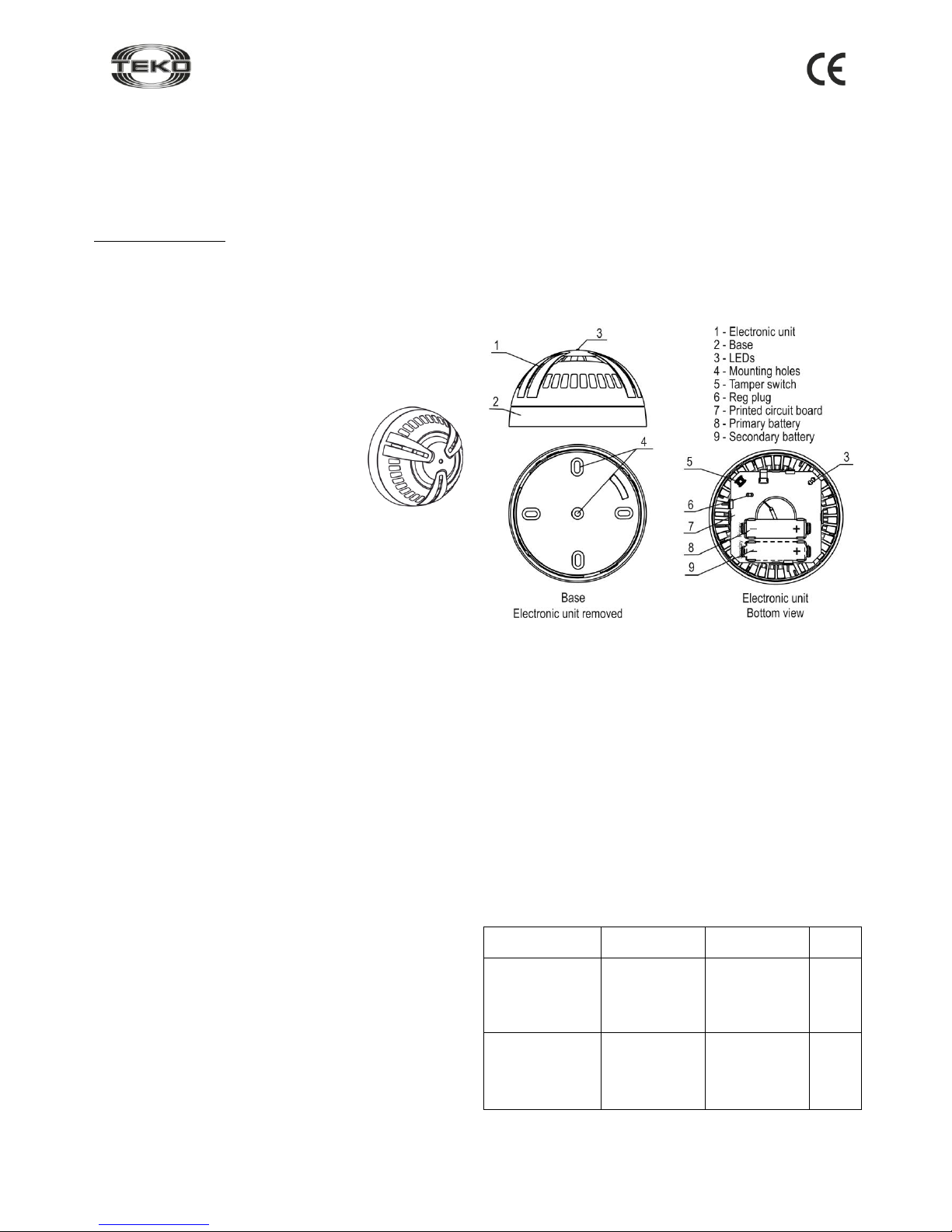
5 Structure
Batteries from delivery package are inserted.
Figure 2
5.1 The detector consists of a removable electronic unit and a
base (Figure 2).
5.2 Inside the electronic unit is a smoke chamber, printed
circuit board (PCB) with radio elements, radio module and
batteries.
5.3 Mounted on PCB is a tamper switch (S1 button), which
results in the «Tampering» notification when the cover is
removed.
5.4 Mounted on PCB are red and white LEDs for detector
operability / wireless network status supervision respectively.
Note - It is not recommended to disassemble the detector’s electronic
unit, as this could damage the detector tuning.
6 Notification Types
Table 1: Notifications processed by LEDs and Control Panel
(or MSS interface)
Notification
Type
Red
LED
White
LED
Control
Panel
Standby
mode start
Lights up for 1
to 40
seconds
Not lit
−
Normal
Lights up for
0.2 seconds
one time per
(60±5)
seconds
Not lit
+
Figure 1
Page 2
Rev. 4245-v3_2_en
2
Fire
Lights up one
time for 10
seconds when
the smoke
density
reaches the
activation
threshold
Not lit
+
Detector failure
Triple blink
every 25
seconds
Not lit
+
Powering up
Not lit
Any
Primary battery
failure
Not lit
Any
+
Secondary
battery failure*
Not lit
Any
+
Power failure
Triple blink
every 25
seconds
Not lit
+
Tampering/
Tamper recovery
Lights up
one time for
0.2 seconds
Not lit
+
Network search
Not lit
Blinks with
frequency of
5Hz for 1 to
60 seconds
−
No network
Not lit
Double blink
every 25
seconds
−
Radio module
failure
Not lit
Triple blink
every 25
seconds
+
+: notification issued; –: notification not issued
*: with secondary battery installed
Notes
1 The «Power failure» notification is processed by the red LED
if both batteries are discharged or if one of the batteries is
missing and the second battery is discharged.
2 If «Primary battery failure» notification appears, replace
the battery within two months.
7 Operating Modes
The detector provides for «Registration» and «Test» modes.
7.1 «Registration» mode is intended for registering the
detector in the wireless network in which it supposed to
operate (see p.8.3).
7.2 «Test» mode is intended for testing electronic and
optical circuits of the detector.
The mode is activated upon a command from the control panel
or LT. Within 5 seconds after the command receipt, the
detector should issue «Test fire» notification (in case of
detector normal operation) or «Detector failure» or «Power
failure» notifications (in case of corresponding failures).
8 Pre-Starting Procedure
8.1 After transportation in conditions differing from those of
operation, keep the detector unpacked for 4 hours in the
expected operating conditions.
8.2 Running Detector. Replacing Batteries
WARNING! Lithium-thionyl-chloride batteries have an effect of
«passivation» to provide the possibility of long-term storage. To
provide battery normal operation after long-term storage, hold
an «activation» procedure.
Step-1
Turn the detector’s electronic unit
counter-clockwise. Remove the
electronic unit from the detector
base.
Step-2
When using one battery to switch the detector ON, insert
the Primary battery.
Note – When using two batteries, it is recommended to
insert the Secondary battery first, and then the Primary
battery. The Secondary battery can be inserted up to 1
minute after inserting the Primary battery.
To replace the battery, remove the old one, and after at
least 30 seconds insert the new one.
The red LED lights up for 1 to 40 seconds – the battery
activation and checking period.
If after 40 seconds the red LED flashes triply every 25
seconds, re-activate the battery by removing it, and after at
least 30 seconds reinserting it.
Warning! If two batteries have been inserted, replace
both batteries.
8.3 Registering the Detector in the Wireless
Network
Detector registration procedure is required for detector
identification in the wireless network in which it is supposed
to operate.
Step-1
According to Astra-Zitadel System Control Panel`s
Operating Manual * perform the following procedure:
1) Install Software ** (MSS Astra-Z, Pconf-Z or MSS Astra
Pro) intended for configuring Control Panel.
2) Create wireless network
Step-2
Perform par.8.2
Step-3
Switch the control panel to Wireless device registration
mode by the method described in the appropriate Control
Panel Operating manual *
Step-4
Initiate detector registration procedure by one of 2
methods:
a) using the LT (step-5);
b) using the Reg plug and the tamper switch (step-6)
WARNING!
Avoid to initiate registration procedure on several
detectors simultaneous
Step-5
Initiating Detector
Registration Using the LT:
- Press the lower button on the
LT and hold until a beam
appears.
- Direct the laser beam at the
detector LED.
- Irradiate the LED for 1 second.
The detector red LED lights up for 2 seconds, and then
the detector switches to wireless network search mode and
the detector white LED blinks at a frequency of 5 Hz.
No more than 10 m
At least 0.1 m
Page 3

Rev. 4245-v3_2_en
3
Step-6
Initiating Detector Registration
Using the Reg Plug and Tamper
Switch:
1) Shortly (for 1-2 seconds) close
the Reg plug with a screwdriver.
The detector switches to registration in wireless network
mode for 60 seconds.
2) Within 60 seconds, shortly (for 0,2-2
seconds) press the tamper switch
on the detector. The detector switches
to wireless network search mode and
the detector`s white LED blinks at a
frequency of 5 Hz.
Step-7
Verify registration procedure:
Once registration procedure completed successfully, the
abbreviated name of detector «SD» appears on the screen
or «SDxxx registered» notification appears on the control
panel`s screen.
Assemble the detector:
- Place the detector’s electronic unit on the base, aligning
the projections on the detector base with the button on the
electronic unit circuit board.
- Press the housing of the detector’s electronic unit against
the base and turn it clockwise firmly.
In case registration procedure failed repeat the
registration procedure, i.e. perform steps 3 and 5 or 3 and
6.
Step-8
After successful registration of the detector, for long term
storage before its installation, it is allowed to switch the
detector OFF by removing the battery or installing a soft
isolator.
When power is supplied, there is no need to re-register the
detector in the same wireless network if it was not intentionally
removed from the network through software or control panel`s
menu.
8.4 Deleting Detector from Wireless Network
Deletion the detector from wireless network is performed
using Software ** or through Control Panel`s menu.
When deleting detector from wireless network, Control Panel
transmits notification about deletion to detector within two
periods of RF supervision time. After receiving the
notification detector issues "No network" notification.
To speed up the deletion procedure:
- remove detector`s cover
- shortly close Reg plug
- press and hold down tamper switch for 8-10 sec.
The detector issues "No network" notification to LED and is
available for registration.
9 Installation
9.1 Location
9.1.1 Install the detector on the ceiling.
9.1.2 The area covered by one detector, as well as the maximum
distance between detectors and between the detector and the
wall, must be determined according to Table 2.
Table 2
Secured room
height,
m
Average area
covered
by one detector, m2
Maximum distance, m
between
detectors
from detector
to wall
up to 3.5
up to 85
9.0
4.5
> 3.5 to 6.0
up to 70
8.5
4.0
> 6.0 to 10.0
up to 65
8.0
4.0
9.1.3 When installing the detector on a sloped ceiling, it should
be installed at the highest point.
9.1.4 Do not cover the detector; smoke particles must freely
penetrate the grating into the smoke chamber.
9.2 Installation Procedure
Step-1
Turn the detector’s electronic
unit counter-clockwise.
Remove the electronic unit
from the detector base.
Step-2
Mark a place on the ceiling,
using the detector base as a
template.
Fasten the base to the
ceiling.
Step-3
Install the detector’s electronic unit onto the fastened base:
- Align the projections on the detector base with the button
on the electronic unit circuit board.
- Press the housing of the detector’s electronic unit against
the base and turn it clockwise firmly.
- Make sure the detector LED issues «Standby mode»
notification.
Page 4

Rev. 4245-v3_2_en
4
Step-4
Activate «Test» mode in accordance
with the appropriate Astra-Zitadel
System Control Panel`s Operating
Manual* or using the LT:
- Press the upper button on the LT;
- Direct the laser beam at the
detector LED;
- Irradiate the LED for 1 second:
In 5 seconds make sure «Fire» notification appears on the
LED – the red LED lights up for 10 seconds. A «Test fire»
event is recorded in the control panel (or MSS interface)
event log.
9.3 To ensure the alarm system reliable operation, testing
and maintenance of the detector is recommended.
Testing should be carried out as follows:
- Check absence/output of the «Failure» notification on the
LED at least once a week;
- Check the detector operability by using a laser tester at least
once a month.
Perform technical maintenance at least once in 3 months
as follows:
- Inspect the detector housing integrity and reliability of its
mounting;
- Purge the detector from contamination;
- Clean the detector’s smoke chamber with compressed air.
Detecting severe dust of smoke chamber (dust level value
greater than 50 units) during the process of testing or issuing
the "Failure" notification requires unscheduled cleaning of the
smoke chamber.
Dust level value is displayed:
- in the “Engineer menu / 2 Wireless network / 5 W/devices
status” for Astra-Z-812M Control Panel;
- in the “Wireless devices / Device type” tab of Monitor
module from Astra-Z MSS for Astra-Z-8945 ver.A Control
Panel, or in the “Wireless devices / Device type” tab of
Monitor module from Astra Pro MSS for Astra-8945 Pro and
Astra-812 Pro Control Panels. Launch test of the detector from
right-click menu (Launch SD/HD test), observe dust level value
in the “Dust level value / Temperature” column.
10 Labeling
The following information is marked on the label attached to the
detector housing:
- manufacturer trademark;
- abbreviated detector designation;
- firmware version;
- month and year (last two digits) of manufacture;
- conformity mark (if the conformity certificate is available);
- bar-code that duplicates textual information.
11 EC Conformity Declarations
This product is in conformity with the provisions of:
R&TTE Directive 1999/5/EC, Article 10.5;
EN 60950: 2001 Safety of information technology equipment;
EN 50371 Generic standard to demonstrate the compliance of lowpower electronic and electrical apparatuses with the basic restrictions
related to human exposure to electromagnetic fields (10 MHz - 300
GHz) – General public;
EN 301489-17 V1.1.1 (09-2000) Electromagnetic Compatibility and
radio spectrum Matters (ERM); Electromagnetic Compatibility (EMC)
standard for radio equipment and services; Part 17: Specific conditions
for wideband data Hiperlan equipment;
EN 300220-1 V1.3.1 (2000-09) Electromagnetic compatibility and
Radio spectrum Matters (ERM); Short range devices; Technical characteristics and test methods for radio equipment to be used in the 25
MHz to 1 000 MHz frequency range with power levels ranging up to
500 mW; Part 1: Parameters intended for regulatory purposes.
Construction of the detector provides for protection class IP41.
12 Recycling
12.1 The detector poses no threat to human life, health or to the
environment; after its service life is over, it can be disposed of without
any special environmental protection measures.
12.2 Recycling of battery cells should be done by delivering used
cells to a trading organization, service centre, manufacturer, or to any
organization accepting used batteries.
13 Warranty Terms
13.1 Quality Management System meets provisions of ISO 9001-2011.
13.2 The manufacturer guarantees the compliance of the detector to
specifications if the user observes required conditions of
transportation, storage, installation and operation.
13.3 The storage warranty period is 5 years and 6 months from the
date of manufacture.
13.4 The operating warranty period is 5 years from the startup date,
but not more than 5 years and 6 months from the date of manufacture.
13.5 The manufacturer guarantees replacement or repair of the
product during the warranty period.
13.6 The warranty doesn’t come into effect in the following
cases:
- not adherence to the operating manual;
- mechanical damage to the detector;
- repair of the detector by any third-party service except for the
manufacturer.
13.7 The warranty applies to the detector only. All equipment from
other manufacturers used with the detector, including batteries, is
covered by its own warranties.
The manufacturer bears no responsibility for death, injury,
property damage or other incidental or premeditated loss based
on user's statement that the device failed to implement its
functions.
* Available for free downloading from www.controlex.eu
and/or integrated with configuring software.
** Available for free downloading from www.controlex.eu.
Sales:
Controlex GmbH
Warranty service and
technical support:
ТЕКО-TD
Philosophenweg 31-33
47051 Duisburg, Germany
Phone: +49 (0) 203 / 393 91 188
Fax: +49 (0) 203 / 393 91 189
GSM: +49 (0) 178 / 218 48 22
E-mail: info@controlex.eu
Web: www.controlex.eu
Prospekt Pobedy str. 19
420138 Kazan, Russia
Phone: +7 (843) 261-55-75
Fax: +7 (843) 261-58-08
E-mail: info@teko.biz
support@teko.biz
Web: www.teko.biz
Made in Russia
 Loading...