

Page 1
Astra-RVC Version TM
Wireless Receiver
Operation Manual
Rev. RVC_TM-v1_3_en
This Operation Manual describes principles of functioning,
proper use, maintenance and service for the wireless receiver
Astra-RVC version TM (Figure 1).
The manufacturer reserves the right to make improvements in
the design of the device without prior notice. The alterations
shall be included into a new edition of the Operation Manual.
List of abbreviations used in this Operation Manual:
RVC – wireless receiver Astra-RVC version TM;
TRC – wireless transmitter Astra-TRC, Astra-TRC version M
and/or Astra-TRC bracelet;
CP – Astra-712 Control Panel or similar.
1 Function
1.1 RVC (receiver) is a stationary device de-
signed to receive signals from TRC (transmitter) through a radio channel and providing a key code in Touch Memory format
through the interface line to CP.
1.2 The manufacturer guarantees a minimum communication range of 150m between the receiver and Astra-TRC (AstraTRC version M), and 50m between RVC
and Astra-TRC bracelet in line of sight in the
area with dry ground in the absence of
strong radio interference, and objects interfering with and reflecting radio waves. The
communication range between the receiver and the transmitter
can be cut down (to 30-60 m) inside concrete buildings and in
presence of radio interference.
2 Specifications
Operating frequency, МHz .................................. .433,82 - 434,02
Power supply voltage, V, max ..................................... 10,5 - 15,0
Current consumption, mА, max .............................................. 25
Technical readiness time, s, max. ................................................. 10
Dimensions (without antenna), mm ............................ 87×54×26,5
Weight (without antenna), kg, max ..................................... 0,056
Operating Conditions:
Temperature range, оС ......................................... from 0 to + 50
Relative air humidity, ................................. .up to 95 at + 35 C
Without moisture condensation
3 Delivery Set
Wireless receiver
Astra-RVC version ТМ ...................................................... 1 pcs.
Antenna ............................................................................ 1 pcs.
Screw 2,9х25 DIN 7982 .................................................... 2 pcs.
Dowel 5х25 ....................................................................... 2 pcs.
Operation Manual ............................................................ 1 copy
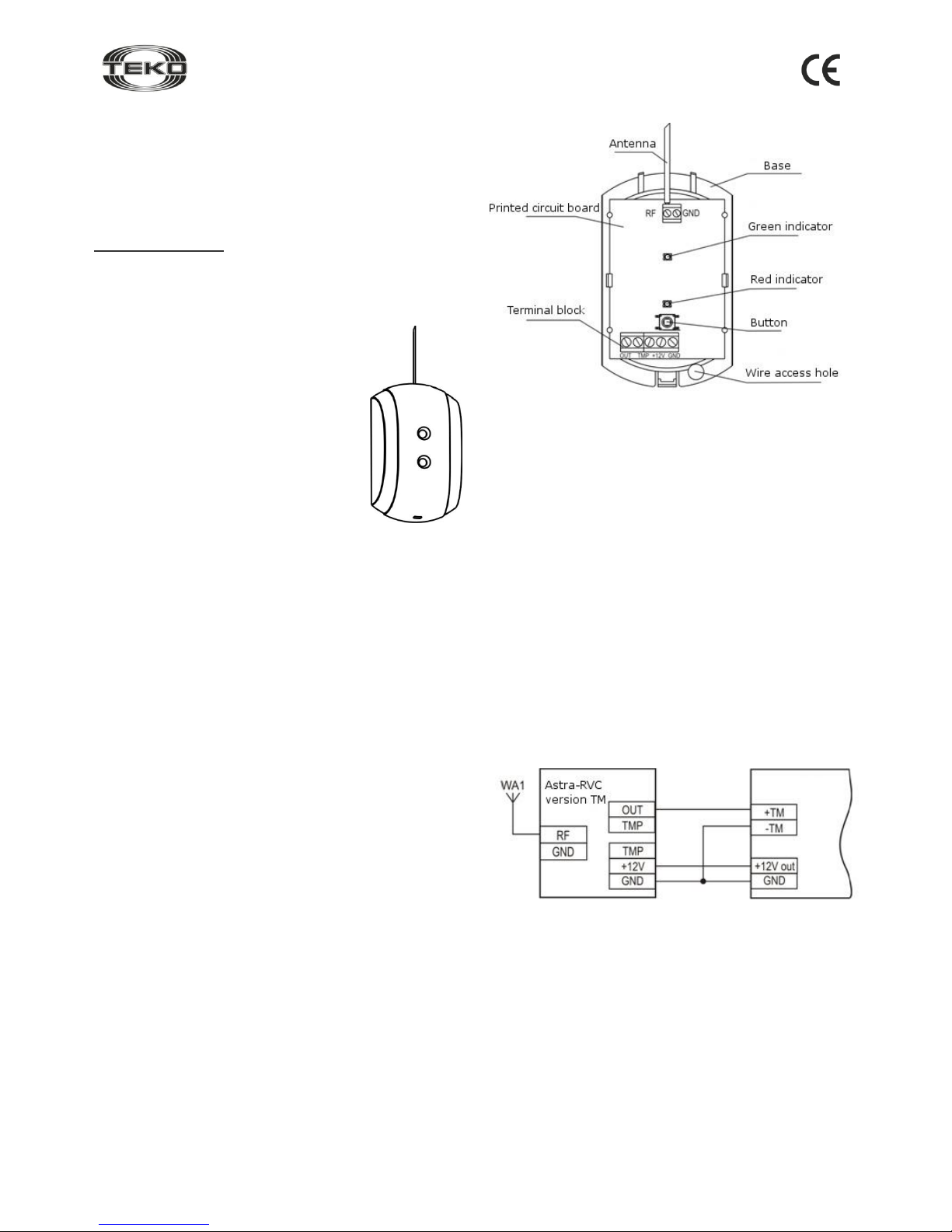
4 Structure
The receiver is designed as a unit consisting of a base, a removable cover and an antenna. There is a printed circuit board
with radio elements inside the unit (Figure 2).
Figure 2
The printed circuit board contains a terminal block:
ТМP is a pair of terminals connected to the button contacts
which are closed if the front cover of the receiver is closed and
opened when the cover is opened;
+ 12V, GND are power supply terminals;
OUT is input/output of the serial interface.
5 Information Capacity
Green indicator blinks 1 time in 4 s. if the receiver functions
properly.
Red indicator switches on when the receiver receives signals
from the transmitter.
The interface line OUT provides a key code in Touch Memory
format.
6 Operability Test
1) Remove the front cover of the receiver (see Paragraph 7).
2) Connect terminals of the receiver to CP as shown in Figure 3.
Figure 3
3) Power CP up.
The green indicator of the receiver will blink 1 time per 4 s.,
the red indicator is off.
4) Press the button on the transmitter.
The red indicator on the receiver will be on, and a key code
will be transmitted to CP in the Touch Memory format through
the interface line.
5) Press the button on the transmitter.
The red indicator of the receiver shall be off, and a key code
will be transmitted to CP in the Touch Memory format.
Each time you press the button, the status of the red indicator
on the receiver will change, and a key code shall be transmitted to CP in the Touch Memory format.
6) Power the receiver down.
Figure 1
CP
Page 2
Rev. RVC_TM-v1_3_en
2
7 Installation
7.1 Select Installation Location
7.1.1 The receiver performs best for optimum coverage when
installed at a maximum height (minimum 2m).
7.1.2 Avoid running power supply cables and the interface line
of the receiver close to heavy duty power lines and high –
frequency cables.
7.1.3 Avoid the following locations for the receiver:
- massive metal constructions or closer than 1m from them;
- closer than 1 m from power mains and metal water or gas pipes
which may cause radio interference;
- lower than 1,5 m above the floor;
- inside metal constructions.
WARNING! Do not place the receiver at a distance less than
10 m from another wireless unit (including its antennas),
which is a source of interference for the receiver. Do not
place the receiver at a distance less than 5 m from the computer (system block and display), uninterruptible power
supply unit and other power equipment.
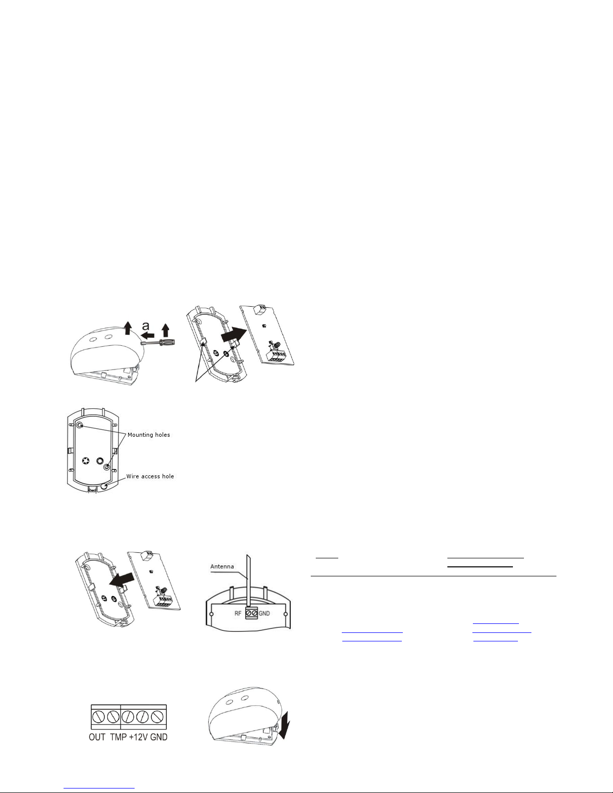
7.2 Installation Procedure
Step-1
Push the base lock from the
cover slot. Remove the cover.
Step-2
Carefully unbend hooks on
the base. Remove the PCB.
Hooks
Step-3
Mark mounting holes
on a flat surface using bottom base of the receiver as
a template.
Insert wires from the
power supply unit and the
interface line through the
wire access hole.
Mount the receiver base.
Step-4
Reinstall the printed circuit board
Step-5
Connect the antenna to
the RF terminal block
Step-6
Wiring to the receiver output
terminals must be performed as
shown in Figure 3.
If necessary, connect ТМP terminals to the alarm loop of CP.
Step-7
Replace the cover (until
the closing click is
heard).
8 Labeling
The label on the receiver case specifies:
- the trademark of the manufacturer;
- abbreviated name of the receiver;
- firmware version;
- month and year (last two digits) of manufacture;
- certification mark;
- barcode which backups the text information.
9 EC Conformity Declarations
This product is in conformity with the provisions of:
R&TTE Directive 1999/5/EC, Article 10.5;
EN 60950: 2001 Safety of information technology equipment;
EN 50371 Generic standard to demonstrate the compliance of lowpower electronic and electrical apparatuses with the basic restrictions
related to human exposure to electromagnetic fields (10 MHz - 300
GHz) – General public;
EN 301489-17 V1.1.1 (09-2000) Electromagnetic Compatibility and
radio spectrum Matters (ERM); Electromagnetic Compatibility (EMC)
standard for radio equipment and services; Part 17: Specific conditions for wideband data Hiperlan equipment;
EN 300220-1 V1.3.1 (2000-09) Electromagnetic compatibility and Radio spectrum Matters (ERM); Short range devices; Technical characteristics and test methods for radio equipment to be used in the 25 MHz
to 1 000 MHz frequency range with power levels ranging up to 500
mW; Part 1: Parameters intended for regulatory purposes.
10 Recycling
The receiver does not pose any threat to life and health of people, as
well as to the environment. After the expiry of its service life period,
the receiver shall be disposed of without special precautions in respect
to the environment.
11 Manufacturer Warranties
11.1 The manufacturer guarantees that the receiver will comply to
technical requirements, provided that the consumers adhere to specified technical conditions of transportation, recommendations on storage and use.
11.2 The warranted shelf life is 5 years 6 months from the manufacturing date.
11.3 The warranted service life is 5 years from the commissioning
date, but not more than 5 years 6 months from manufacturing date.
11.4 The manufacturer must repair or replace the receiver within the
warranty period.
11.5 The warranty does not become effective in the following cases:
– failure to comply with this Operation Manual;
– mechanic damage of the receiver;
– if the receiver is improperly repaired by anyone other than the
manufacturer.
11.6 The warranty applies only to the receiver. All other equipment of
other manufacturers used with the receiver is subject to other manufacturer’s warranties.
11.7 In no case shall the manufacturer be liable for any death, physical injury or property damage, or any other accidental or intentional
loss based on claim that the receiver failed to perform its functions.
Sales:
Controlex GmbH
Warranty service and
technical support:
ТЕКО-TD
Philosophenweg 31-33
47051 Duisburg, Germany
Phone: +49 (0) 203 / 393 91 188
Fax: +49 (0) 203 / 393 91 189
GSM: +49 (0) 178 / 218 48 22
E-mail: info@controlex.eu
Web: www.controlex.eu
Prospect Pobedy str. 19
420138 Kazan, Russia
Phone: +7 (843) 261-55-75
Fax: +7 (843) 261-58-08
E-mail: info@teko.biz
support@teko.biz
Web: www.teko.biz
Made in Russia
b
c
 Loading...