

Page 1
Rev. R-v9_2_en
1
Astra-R Kit
Wireless Alarm System
Operation Manual
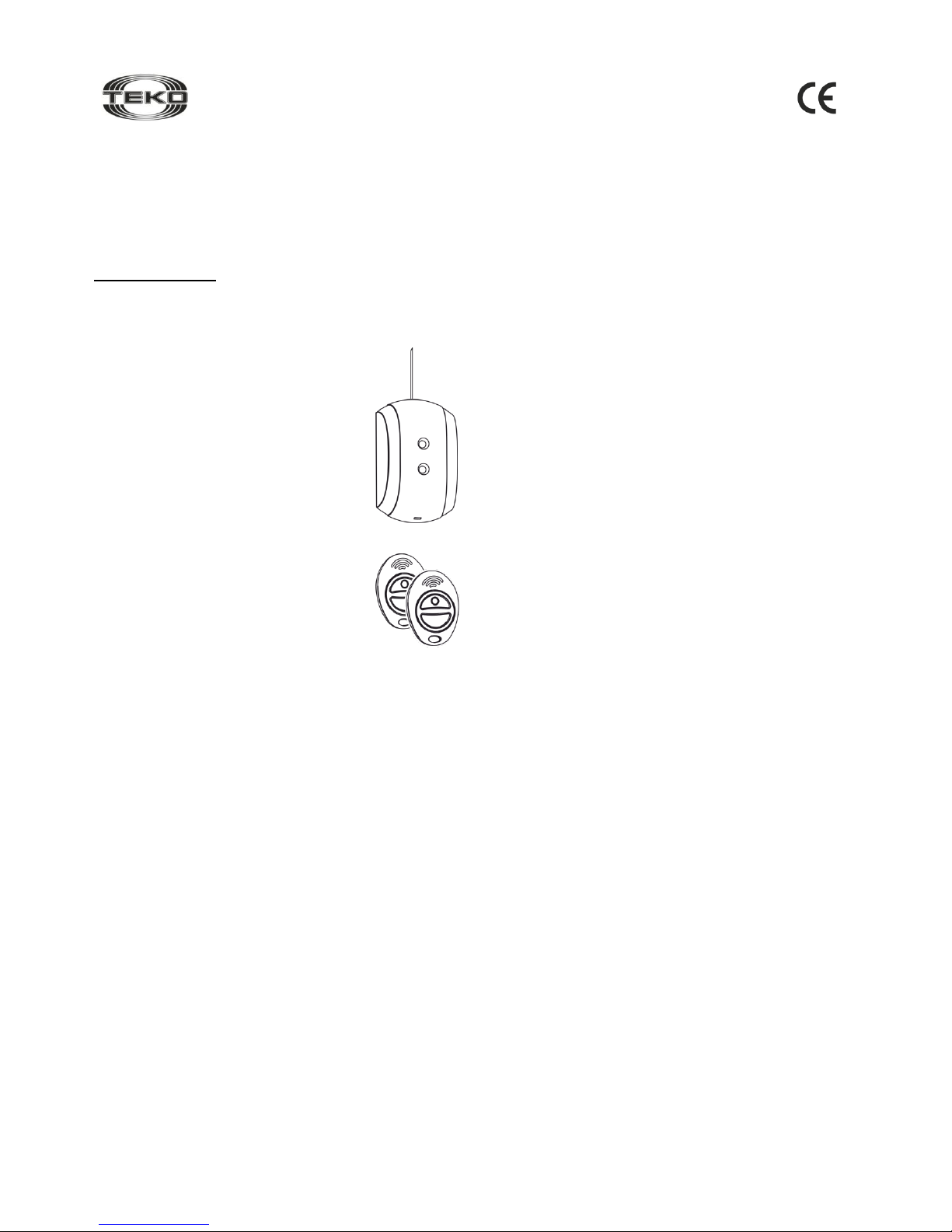
This operation manual describes principles of functioning, proper
use, maintenance and service for the wireless alarm system AstraR Kit (Figure 1).
The manufacturer reserves the right to make improvements in the
design of the devices without prior notice. The alterations shall be
included into a new edition of the Operation Manual.
List of abbreviations used:
WAS is a wireless alarm system Astra-R Kit;
RVC is a wireless receiver Astra-RVC;
TRC is a wireless transmitter Astra-TRC;
IP is an indication panel Astra-931;
CP is a Control Panel Astra-712 or similar one.
1 Function
1.1 Alarming System
Organization of individual protection and protection of sites by transmitting alarm signals from
registered wireless transmitters via radio and
generating notifications through actuation of
built-in relays, and indication of transmitter numbers on the display of indication panel Astra-931.
1.2 Remote Control of Electrically
Operated Mechanisms
Organization of control through actuation of built-in
relays within preset time or by latching upon receipt
of signals from registered transmitters.
2 Components
2.1 RVC
2.1.1 RVC is a stationary device designed to:
receive signals from wireless transmitters via radio, decode
and identify the received signals,
generate notifications by actuation of integrated relays,
transmit numbers of transmitters to IP Astra-931 through seri-
al interface.
2.1.2 RVC is able to register up to 25 TRCs, and it saves this information when power is off.
2.1.3 RVC is powered from an external stabilized power supply
unit Astra-712/0 or a similar one.
2.2 TRC
2.2.1 TRCs are small self-powered wireless transmitters designed
to generate and transmit encoded signals upon pressing a button
on the transmitter.
2.2.2 In order to avoid discharging of the battery TRC will stop
transmitting in 10 s after the button is pressed, if the button is held
down.
2.3 The manufacturer guarantees a minimum communication
range of 150m between the receiver and the transmitter in line of
sight in areas with dry ground, and in the absence of strong radio
interference, and objects interfering with and reflecting radio
waves. The communication range between the receiver and the
transmitter can be cut down to 30 m inside concrete buildings and
in presence of radio interference.
3 Specifications
Operating frequency, МHz .......................... .from 433.82 to 434.02
Technical Parameters of RVC
Power supply voltage, V ............................................. from 10 to 15
Current consumption, mА, max ................................................... 60
Maximum switching voltage of relay contacts
with load current 1 А, V, max .................................................... 250
Technical readiness time, s, max ................................................ 10
Overall dimensions (without antenna), mm .............. 87 × 54 × 26.5
Weight (without antenna), kg, max ......................................... 0.056
Technical Parameters of TRC
Power supply voltage provided by integrated
battery CR 2430, V, max ............................................................... 3
Output power, mW, max .............................................................. 10
Current consumption:
- in standby mode, µA, max ........................................................... 5
- in radio transmission mode, mА, max ....................................... 25
Overall dimensions, mm ........................................... 56 × 40 × 12.5
Weight, kg, max ....................................................................... 0.04
Technical Parameters of IP
Number of bits, max ................................ ...................................... 2
Character height, mm, max ......................................................... 14
Power supply voltage, V ............................................. from 10 to 15
Current consumption, мА, max ................................................. 130
Technical readiness time, s, max .................................................. 5
Overall dimensions, mm .............................................. 80 50 25
Weight, kg, max ....................................................................... 0.05
Operating Conditions
Temperature range for RVC, оС ............................ from 0 up to +50
Temperature range for TRC, оС ............................ from 0 up to +50
Temperature range for IP, оС ............................. from -30 up to +50
Relative air humidity, ....................................... .up to 95 at + 35 C
without moisture condensation
4 Delivery Set
Wireless transmitter Astra-TRC .............................................. 2 pcs.
Wireless receiver Astra-RVC .................................................. 1 pcs.
Antenna .................................................................................. 1 pcs.
Screw 2.9 × 25 ....................................................................... 2 pcs.
Dowel 5 × 25 .......................................................................... 2 pcs.
Operation Manual ................................................................. 1 copy.
Notes
1 TRC is registered in RVC.
2 The indication panel Astra-931 shall be delivered separately.
TRC
Figure 1
RVC
Page 2
Rev. R-v9_2_en
2
5 Structure
5.1 RVC
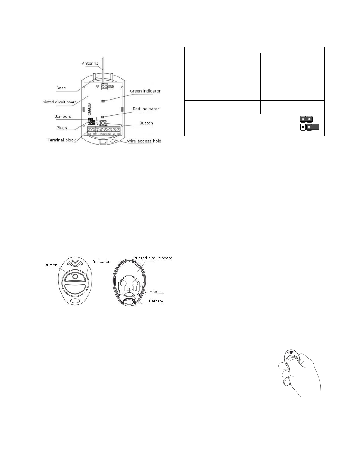
The receiver is designed as a unit consisting of a base, removable
cover and antenna. There is a printed circuit board with radio elements inside the unit (Figure 2).
Figure 2
The printed circuit board contains a terminal block:
OUT is an input/output of serial interface;
ТМP is a pair of terminals connected to the button contacts which
are closed if the front cover of the receiver is closed, and opened
when the cover is opened;
+ 12V, GND are power supply terminals;
NO is a terminal connected to a normally open relay contact;
NC is a terminal connected to a normally closed relay contact;
COM is a terminal connected to a common relay contact.
The printed circuit board contains green and red indicators for
RVC operability supervision and notification indicating.
5.2 TRC
The wireless transmitter is designed as a key fob consisting of a
front cover and a base (Figure 3).
The front cover contains a button and a printed circuit board with
radio elements.
The printed circuit board contains an indicator controlling operation of the TRC.
Figure 3
6 Information Capacity
6.1 RVC
Green indicator:
blinks 1 time per 4 s, if RVC functions properly;
illuminates during registration of TRC into RVC memory;
blinks 2 times per 1 s within 4 s indicating successful regis-
tration;
blinks 2 times and switches to blinking 1 time per 4s indicating
failed registration.
Red indicator indicates status of relay contacts:
illuminates when normally open (NO) contacts are closed.
The interface line OUT transmits TRC numbers and informa-
tion on discharged battery to IP Astra-931.
6.2 TRC
Indicator:
illuminates when the button is pressed indicating transmis-
sion of encoded signals;
blinks when the button is pressed indicating discharged ba ttery.
7 Operation Modes
Operation modes for WAS shall be set up with jumpers and RVC
button.
Operation mode
Jumper
Button state
when the receiver is
switched on
F1
F2
T
TRC registration
+ + л
Not pressed
Programming of relay switching time
+ + +
Pressed
Relay actuation with
latching
– – –
Any
Relay actuation with
time delay
– – +
Any
"+" – jumper installed on two plug pins,
"–" – jumper removed (or installed on one plug
pin),
"a" – any jumper position
Note: jumpers must be removed or installed when the power is
off, unless otherwise stated.
8 Pre-starting Procedure
8.1 It is advisable to leave the unpacked receivers and transmit-
ters in operating conditions for at least 2 hours, after they have
been transported in conditions which differ from operating one.
8.2 All the TRCs included in the delivery set have already been reg-
istered in RVC. Additional TRCs must be registered in RVC memory
as described in 8.4.2 of the present Operation Manual.
8.3 Clearing RVC Memory
Clear (erase) the receiver memory before registration of the first
transmitter.
1) Remove the front cover of the receiver (see 11.2).
2) Install jumpers on F1 and F2 plugs.
3) Power the receiver up.
The green indicator on the receiver will blink 1 time per 4 s.
4) Press and hold the button until the green indicator is off. The
receiver memory is clear.
5) Power the receiver down.
8.4 TRC Registration in RVC Memory
Transmitters shall be registered one after another in any succession.
After successful registration the receiver shall “remember” a
unique serial number of the transmitter in its non-volatile memory
and assign a reference sequential number following the order of
registration.
An illustrated manual describing registration of transmitters is provided in Annex A.
8.4.1 Registration of First Two TRCs
1) Remove the front cover of the receiver (see 11.2).
2) Install jumpers on F1 and F2 plugs.
3) Power the receiver up.
The green indicator on the receiver will blink 1 time per 4 s.,
while the red indicator is off.
4) Briefly press the button on the receiv-
er. The green indicator will illuminate. The
receiver will switch to the registration
mode for 30 s.
5) Press the button on the transmitter
which is to be registered (Figure 4). The
green indicator on the receiver will be off.
6) Press again the button on the trans-
mitter which is to be registered. (Figure 4).
The green indicator on the receiver will be
blinking 2 times per 1 second within 4 seconds.
It will indicate successful registration.
The green indicator will blink 2 times and switch to the standard
mode (blink 1 time per 4 seconds). It will indicate a failed registration.
Possible causes of failed registration:
Figure 4
Page 3

Rev. R-v9_2_en
3
– transmitter has been earlier registered – if you press the button
on the transmitter the red indicator will illuminate on the receiver;
– registration procedure is wrong – repeat registration steps till
8.4.1 or 8.4.2.
7) Power the receiver down.
8) Remove jumpers from F1 and F2 plugs.
9) Close the receiver cover.
8.4.2 Registration of Third and the Following TRCs
1) Remove the front cover of the receiver (see 11.2).
2) Install jumpers on F1 and F2 plugs.
3) Power the receiver up.
The green indicator on the receiver will blink 1 time per 4 s, the
red indicator is off.
4) Briefly press the button on the receiver. The green indicator
will illuminate. The receiver will switch to the registration mode for
30 s.
5) Press the button on one of two transmitters registered firstly
(Figure 4). The red receiver`s indicator will illuminate.
6) Immediately, press the button on the transmitter which is to
be registered (Figure 4). The green indicator on the receiver will
be off.
7) Press the button on the transmitter which is to be registered
again. The green indicator on the receiver will be blinking 2 times
per 1 second within 4 seconds, and the red indicator will be off.
It will indicate successful registration.
The green indicator will blink 2 times and switch to the standard
mode (blink 1 time per 4 seconds). It will indicate a failed registration.
Possible causes of failed registration see in 8.4.1.
8) Power the receiver down.
9) Remove jumpers from F1 and F2 plugs.
10) Close the front cover of the receiver.
8.5 Programming of Relay Switching Time
Default setup – 2 s.
8.5.1 Programming the Relay for a Switching Time
from 2 to 4 Minutes
1) Remove the front cover of the receiver (see 11.2).
2) Remove jumper from the T plug, install jumpers on F1 and F2
plugs.
3) Press the button on the receiver, and while holding it, power
the receiver up.
4) Release the button.
5) Wait during the required (programmed) time interval (from 2 s
till 4 min) and install jumper on T plug.
6) Power the receiver down.
7) Remove jumpers from F1 and F2 plugs.
8) Close the front cover of the receiver.
8.5.2 Accelerated Programming of Relay Switching
Time from 20s to 30 min
In case of accelerated programming, the programming time is reduced 10 times, the programming step being 10-15 s.
1) Remove the front cover of the receiver (see 11.2).
2) Remove jumper from T plug, install jumpers on F1 and F2
plugs.
3) Press the button on the receiver, and while holding it, power
the receiver up.
4) Release the button, and then press for 1-2 s.
5) Wait during the required (programmed) time interval reduced
10 times (from 2 s to 3 min), and install jumper on T plug.
6) Power the receiver down.
7) Remove jumpers from F1 and F2 plugs.
8) Close the front cover of the receiver.
8.5.3 Default Setting of Relay Switching Time (2 s)
1) Remove the front cover of the receiver (see 11.2).
2) Install jumpers on T, F1 and F2 plugs.
3) Press the button on the receiver, and while holding it, power
the receiver up.
4) Release the button.
5) Power the receiver down.
6) Remove jumpers from F1 and F2 plugs.
7) Close the receiver cover.
9 Operability Test
9.1 Relay Actuation with Latching
1) Remove the front cover of the receiver (see 11.2).
2) Remove jumpers from T, F1 and F2 plugs.
3) Connect terminals of the receiver to IP Astra-931 and power
supply unit as shown in Figure 5.
Figure 5
4) Power the receiver and the indication panel Astra-931 up.
The green indicator of the receiver will blink 1 time per 4 s., the
red indicator is off.
5) Press the button on the transmitter (Figure 4).
The red indicator will be on.
Normally open (NO) relay contacts will close.
The indication panel Astra-931 will display the number of the
transmitter which sent the signal. If the battery in the transmitter is
low, the number will blink.
6) Press the button on the transmitter (Figure 4).
The red indicator will be off.
The relays will return to the initial status.
The relay and red indicator status of the receiver will change with
each pressing the button on the transmitter.
7) Power the receiver down.
9.2 Relay Actuation with Time Delay
1) Remove the front cover of the receiver (see 11.2).
2) Install jumper on T plug, remove jumpers from F1 and F2
plugs.
3) Connect terminals of the receiver to the indication panel Astra-
931 and power supply unit as shown in Figure 5.
4) Power the receiver and the indication panel Astra-931up.
The green indicator of the receiver will blink 1 time per 4 s, while
the red indicator is off.
5) Press the transmitter button (Figure 4).
The red indicator will be on, and the relay will be actuated within
the preset time interval.
The indication panel Astra-931 will display the number of the
transmitter which sent the signal. If the battery in the transmitter is
low, the number will blink.
6) Power the receiver down.
WARNING! If you press the button on the transmitter more
than 15 times outside WAS coverage area, the synchronization between the receiver and the transmitter will be disrupted, and no identification shall occur. To synchronize the
equipment again, reenter the WAS coverage area and press
the button on the transmitter 2 times.
10 Replacing TRC Battery
1) Open the front cover of TRC.
2) Remove old battery.
3) Install a new battery in maximum 10s.
4) Close the front cover of TRC.
Page 4

Rev. R-v9_2_en
4
11 Installation
11.1 Select Installation Location
11.1.1 The receiver performs best for optimum coverage when in-
stalled at a maximum height (minimum 2m).
11.1.2 Avoid running power supply cables and the interface line of
the receiver close to heavy duty power lines and high –frequency
cables.
11.1.3 Avoid the following locations for the receiver:
- massive metal constructions or closer than 1m from them;
- closer than 1 m from power mains and metal water or gas pipes
which may cause radio interference;
- lower than 1,5 m above the floor;
- inside metal constructions.
WARNING! Do not place the receiver at a distance less than 10 m
from another wireless unit (including its antennas), which is a
source of interference for the receiver. Do not place the receiver
at a distance less than 5 m from the computer (system block and
display), uninterruptible power supply unit and other power
equipment.
11.2 RVC Installation procedure
Step-1
Push the base lock from the
cover slot. Remove the cover.
Step-2
Carefully bend the hooks on the
base. Remove the PC board.
Step-3
Mark mounting holes on a
flat surface using receiver base
as a template.
Insert wires from the power
supply unit and interface line
through the wire access hole.
Mount the receiver base.
Step-4
Reinstall the printed circuit board
Step-5
Connect the antenna to
RF terminal block
Step-6
Wiring to the receiver output terminals must be performed as
shown in Figure 5.
If necessary, connect ТМP terminals to the alarm loop of CP.
Step-7
Replace the cover (until
the closing click is heard).
12 Labeling
The label on the receiver case specifies:
- the trademark of the manufacturer;
- abbreviated name of the receiver;
- firmware version;
- month and year (last two digits) of manufacture;
- certification mark;
- barcode which duplicates textual information.
13 EC Conformity Declarations
This product is in conformity with the provisions of:
R&TTE Directive 1999/5/EC, Article 10.5;
EN 60950: 2001 Safety of information technology equipment;
EN 50371 Generic standard to demonstrate the compliance of lowpower electronic and electrical apparatuses with the basic restrictions
related to human exposure to electromagnetic fields (10 MHz - 300
GHz) – General public;
EN 301489-17 V1.1.1 (09-2000) Electromagnetic Compatibility and
radio spectrum Matters (ERM); Electromagnetic Compatibility (EMC)
standard for radio equipment and services; Part 17: Specific conditions for wideband data Hiperlan equipment;
EN 300220-1 V1.3.1 (2000-09) Electromagnetic compatibility and Radio spectrum Matters (ERM); Short range devices; Technical characteristics and test methods for radio equipment to be used in the 25 MHz
to 1 000 MHz frequency range with power levels ranging up to 500
mW; Part 1: Parameters intended for regulatory purposes.
14 Recycling
14.1 WAS kit does not pose any threat to life and health of people, as
well as to the environment. After the expiry of its service life period,
WAS shall be disposed of without special environmental precautions.
14.2 Waste batteries must be returned to the trading organization,
service center, and manufacturer or to a recycling organization.
15 Manufacturer Warranties
15.1 The manufacturer guarantees that WAS will comply to technical
requirements, provided that the consumers adhere to specified technical conditions of transportation, recommendations on storage and use.
15.2 The warranted shelf life for RVC and IP is 5 years 6 months from
the manufacturing date. The warranted shelf life for TRC is 1 year 6
months from the manufacturing date.
15.3 The warranted service life for RVC and IP is 5 years from the
commissioning date, but not more than 5 years 6 months from manufacturing date. The warranted service life for TRC is 1 year from the
commissioning date, but not more than 1 year 6 months from manufacturing date.
15.4 The manufacturer must repair or replace WAS within the warranty period.
15.5 The warranty does not become effective in the following
cases:
– failure to comply with this Operation Manual;
– mechanic damage of WAS;
– if WAS is improperly repaired by anyone other than the manufacturer.
15.6 The warranty applies to WAS only. All other equipment of other
manufacturers used with WAS is subject to other manufacturer’s warranties.
In no case shall the manufacturer be liable for any death, physical injury or property damage, or any other accidental or intentional loss based on claim that WAS failed to perform its functions.
Sales:
Controlex GmbH
Warranty service and
technical support:
ТЕКО-TD
Philosophenweg 31-33
47051 Duisburg, Germany
Phone: +49 (0) 203 / 393 91 188
Fax: +49 (0) 203 / 393 91 189
GSM: +49 (0) 178 / 218 48 22
E-mail: info@controlex.eu
Web: www.controlex.eu
Prospect Pobedy str. 19
420138 Kazan, Russia
Phone: +7 (843) 261-55-75
Fax: +7 (843) 261-58-08
E-mail: info@teko.biz
support@teko.biz
Web: www.teko.biz
Made in Russia
b
c
Page 5

Rev. R-v9_2_en
5
V V V
green
red
green
red
green
red
green
red
green
red
green
red
Page 6

Rev. R-v9_2_en
6
green
red
green
red
green
red
green
red
green
red
green
red
V
 Loading...