

Page 1
Astra-942
Laser Tester
Operation Manual
Revision 942-v1_1_en
1
This operation manual is intended for studying operating
principles, proper use, storage, and maintenance of the
Astra-942 laser tester (Figure 1).
List of Abbreviations:
Astra-421 ver.RF2 - wireless optoelectronic smoke detector
with two-way radio;
Astra-4511 ver.RF2 – wireless manual fire alarm call point
with two-way radio;
MC - Astra-Z-3345 - wireless magnetic contact door opening
detector;
SD - Astra-Z-4245 or Astra-421 ver.RF2 wireless smoke
detector;
FCP - Astra-Z-4545 or Astra-4511 ver.RF2 wireless manual fire
alarm call point;
IR - Astra-Z-5145 wireless PIR motion detector;
AC - Astra-Z-6145 wireless acoustic glass break detector.
1 Purpose
1.1 The laser tester is intended for
launching of the registration process for
detectors (IR, FCP, SD, MC and AC) in
the wireless network, testing them
remotely, and searching for the best
operating data delivery route within the
network.
1.2 Power is supplied to the laser tester
from 2 built-in CR2430-type battery
cells of 3.0 V.
Note: The more common CR2032-type
battery cells may be used. In this case,
the battery cell lifetime is reduced.
1.3 The tester has protection against
battery cell polarity reversal.
2 Specification
Effective range for SD, m, minimum ..................................... 10
Effective range for FCP, IR, MC and AC, m, minimum ........... 5
Emission power, mWt, maximum ........................................... 5
Power supply voltage, V ......................................................... 3
Current consumption in transmission
mode, mA, minimum............................................................. 10
Emission wavelength, nm ........................................ 630 to 680
Overall dimensions, mm, maximum...................... 77 40 15
Weight, kg, maximum ........................................................ 0.03
Operating Conditions
Temperature range, °C ..................................... from -10 to +55
Relative air humidity, % ............................... up to 93 at +40 °C
without moisture condensation
3 Package Contents
Astra-942 Laser tester ..................................................... 1 pcs.
Operation Manual ........................................................... 1 copy
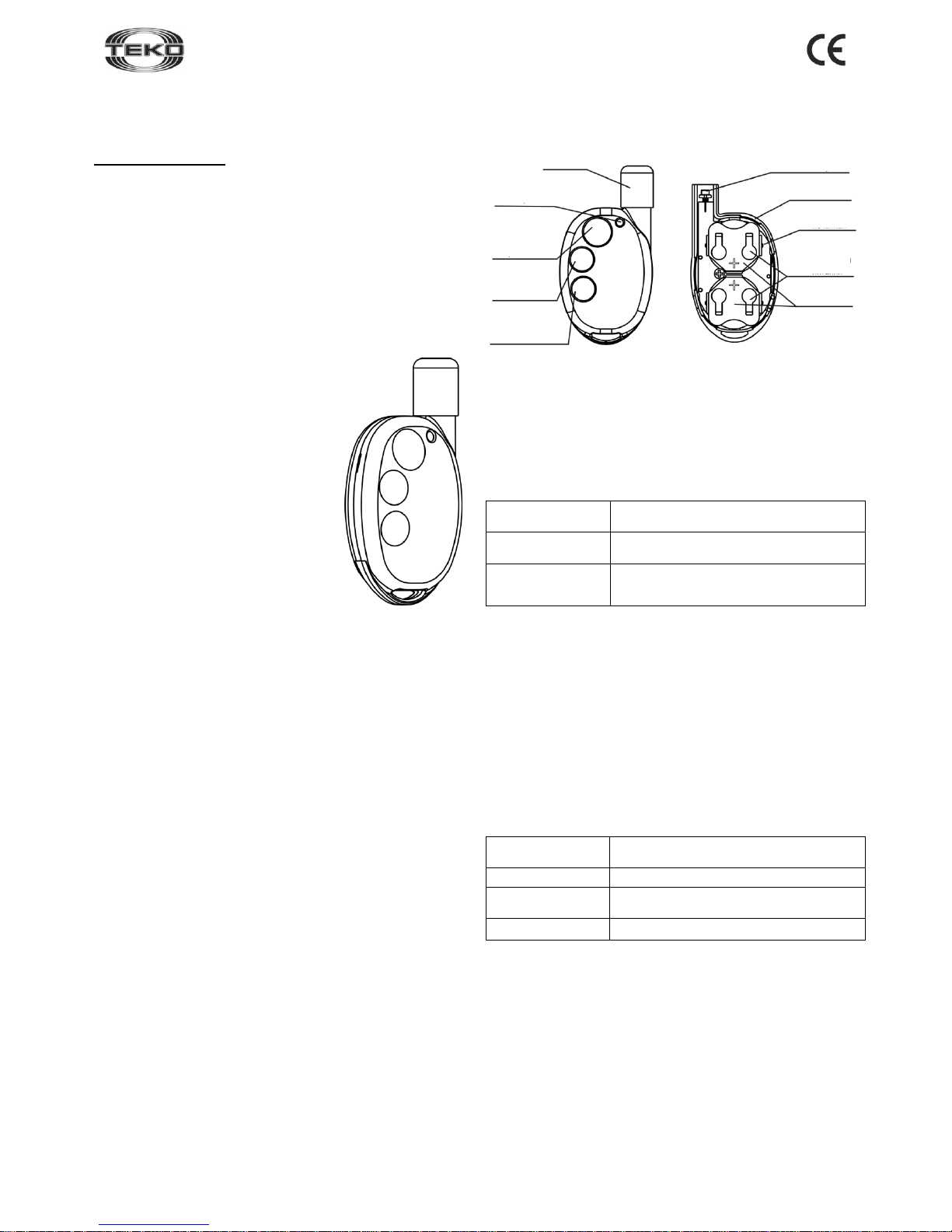
4 Structure
Structurally the laser tester is designed as a key fob, consisting of
a cover (front side) and a base (Figure 2).
Figure 2
Mounted in the cover are buttons and a printed circuit board
with radio elements and battery cells. The base is fastened to
the cover by a screw.
Mounted on PCB is the LED for laser tester operability
supervision.
5 Notifications
Table 1: Notifications processed by LED
Notification
Type
LED
Normal
Lights up once for 0.1 seconds when
pressing of any button
Battery discharge
Blinks continuously for entire time any
button is pressed
6 Operation
WARNING! LASER EMISSION! DO NOT POINT DIRECTLY
AT SOMEBODY’S EYES!
6.1 After transportation in conditions differing from those of
operation, laser tester must be kept unpacked for 4 hours in
the expected operating conditions.
6.2 Focus the laser into a narrow beam:
- Hold and press any button.
- Move the end cap up and down to minimize the
diameter of the dot at the test distance.
- Release the button.
6.3 Test procedure:
Table 2: Purpose of Buttons
Button
Purpose
Button 1
Launch test (send test alarm)
Button 2
Launch network optimization (search for
optimal data delivery route)
Button 3
Launch detector registration
Notes
1. Button 1 is used for testing SD operability only; for other
detectors, this button is used for checking receipt of messages
only.
2. Button 2 is not operable in Astra-421 ver.RF2 and Astra4511 ver.RF2.
- Press the appropriate button and direct the laser beam at the
detector LED.
- Irradiate the LED for 1 second.
- Release the button.
Within no more than 5 seconds, the detector should indicate its
current status.
Figure 1
LED
Test
launch
button
Network
optimization
button
Registration
launch
button
Base
Printed circuit
board
“+” contacts
Battery
cells
End cap
Sender
Page 2
Revision 942-v1_1_en
2
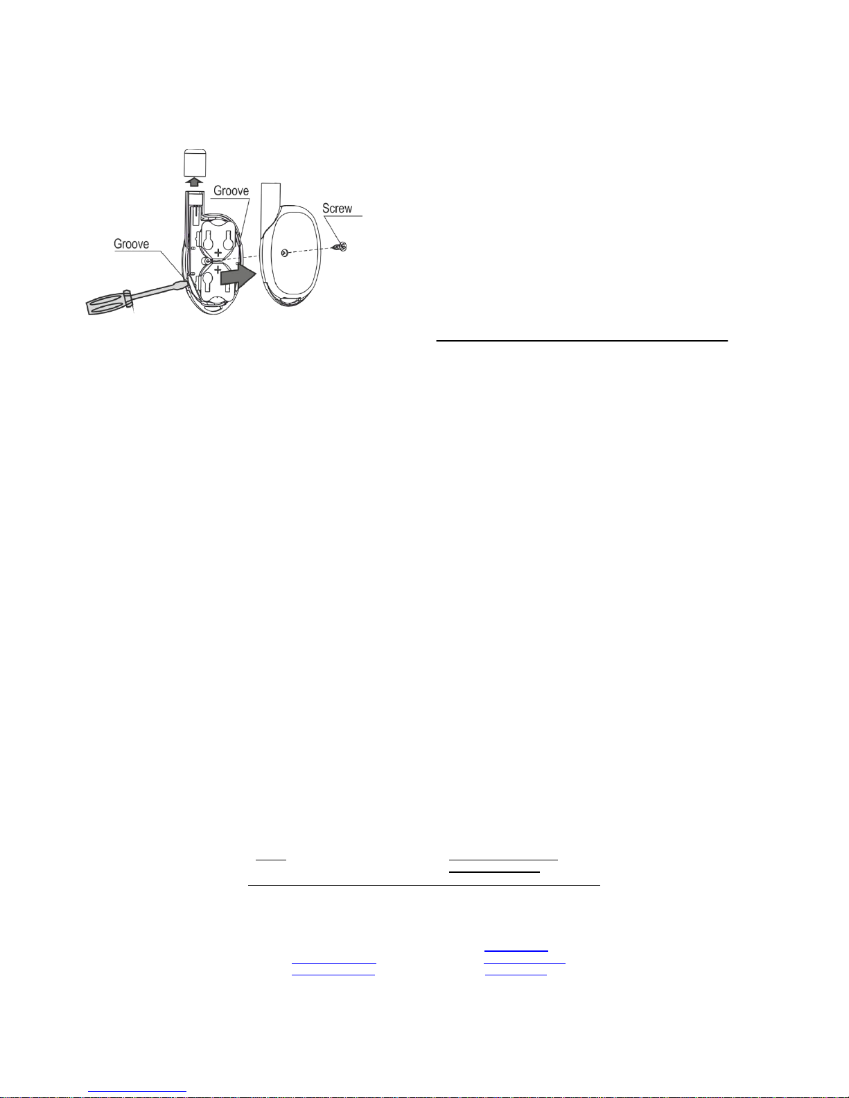
6.4 Replacing Battery Cells:
- Remove the end cap.
- Unfasten the screw.
Insert screwdrivers into each of the grooves in the tester
housing in turn and remove the base.
- Replace the battery cells.
- Reassemble the tester by following these steps in reverse.
7 Manufacturer Warranty
7.1 The manufacturer guarantees the compliance of the product to
specifications on condition that user observes required conditions of
transportation, storage, installation and operation.
7.2 The storage warranty period is 2 years and 6 months from the
date of manufacture.
7.3 The operating warranty period is 2 years from the startup date,
but not more than 2 years and 6 months from the date of
manufacture*.
7.4 The manufacturer guarantees replacement or repair of the
product during the warranty period.
7.5 The warranty doesn’t come into effect in the following cases:
- not adherence to instructions of the operation manual;
- mechanical damage to the device;
- repair of the laser tester by a service apart from the Manufacturer.
7.6 The warranty applies to the laser pointer only. All equipments
from third-party manufacturers used in conjunction with the device,
including batteries, are subject to their own warranty terms and
conditions.
The manufacturer bears no responsibility for death, injury,
property damage or other incidental or premeditated loss based
on user's statement that the device failed to implement its
functions.
*The warranty period does not apply to battery cells.
Sales:
Controlex GmbH
Warranty service and
technical support:
ТЕКО-TD
Philosophenweg 31-33
47051 Duisburg, Germany
Phone: +49 (0) 203 / 393 91 188
Fax: +49 (0) 203 / 393 91 189
GSM: +49 (0) 178 / 218 48 22
E-mail: info@controlex.eu
Web: www.controlex.eu
Prospect Pobedy str. 19
420138 Kazan, Russia
Phone: +7 (843) 261-55-75
Fax: +7 (843) 261-58-08
E-mail: info@teko.biz
support@teko.biz
Web: www.teko.biz
Made in Russia
 Loading...