

Page 1

Revision 712-0v6_3_en
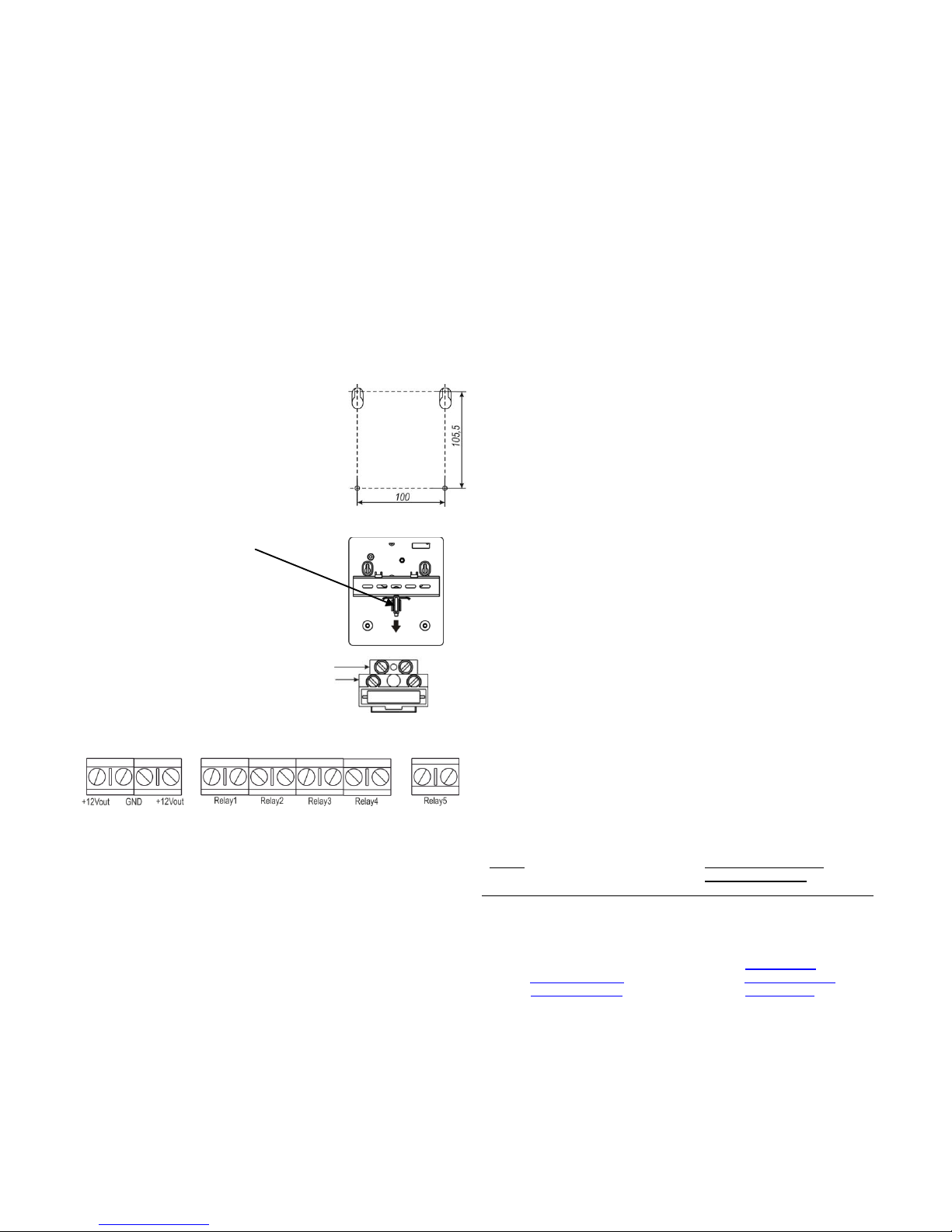
Figure 1
«Astra-712/0»
Power Supply Unit
Operating Manual
The present operating manual is intended for studying operation
principle, running conditions and maintenance of redundant power supply unit Astra-712/0 (hereinafter “PS unit”) (Figure 1).
1 Function
The PS unit is a DC power supply for security system components or other electronic devices with
operational voltage 12 V.
2 General information
2.1 The PS unit is designed to work with AC
network of voltage 220V.
2.2 In case of temporal shutdown and recovery of supply voltage 220V
the PS unit provides for automatic switching to working with built-in accumulator battery (hereinafter “battery”) and switching back to AC network.
2.3 The PS unit has protection from low-voltage discharge of the battery.
2.4 The PS unit has protection from polarity reversal of the battery.
2.5 The PS unit has protection from short-circuit of a battery charge
circuit.
2.6 The PS unit has protection from short-circuit and overload on sec-
ondary power supply.
2.7 The PS unit has primary voltage 220V switch.
2.8 The PS unit has primary circuit 220V protection fuse.
2.9 The PS unit has 5 Relay outputs for issuing informational signals to ex-
ternal circuits.
3 Specifications
Rated output voltage of power supply
when working with AC network, V ................................................ 12 ± 5 %
Output voltage when working with battery, V ...............from 10,2 up to 13,2
Maximum load current, A, not exceeding ................................................. 1
Output variable component (pulsing) -
– peak value, mV ................................................................................. 100
Current consumption, A, not exceeding ................................................ 0,2
Network voltage, V ....................................................... from 187 up to 242
Technical readiness time, s, not exceeding ............................................ 10
Capacity of built-in battery, Ah ....................................... from 7,0 up to 7,2
Charge time of fully discharged battery, h, not exceeding ...................... 24
Voltage of battery cut off, V ........................................................ 10,7 0,3
Battery charge with DC voltage, V ............................................. 14,2 ± 0,2
Battery charge current limit, mA ................................................... 360 ± 30
Weight, kg, not exceeding:
- without battery .................................................................................. 0,52
- with battery ............................................................................................ 3
Overall dimensions, mm, not exceeding ............................. 165 × 190 × 80
Operation conditions
Temperature range, °C
- without battery ............................................................... from - 30 to + 50
- with battery ................................................................... from - 10 to + 50*
Relative air humidity, % ............................................................. up to 93 at + 40 °С
Without moisture condensation
_____________________________________
* At temperature out of range 0-40ºC battery charging time increases by 1.5 times.
4 Delivery Set
Redundant power supply unit Astra-712/0 ........................................ 1 pcs.
Screw 3,9 × 32 .................................................................................. 4 pcs.
Dowel 6 × 30..................................................................................... 4 pcs.
Operating manual ............................................................................ 1 copy
Note – Battery is supplied separately.
5 Structure
Figure 2
The PS unit is designed as a block with removable cover.
Inside the block are mounted PCB with radio elements and socket with
system voltage fuse-switch (figure 2).
On circuit-board there are 5 two-colored LED indicators and built-in buzzer which are used to control the power supply unit operating ability.
Mounted on PCB are screw terminals for PS unit status information
issuing:
Relay1 – 12V output state,
Relay2 – 220 AC network state,
Relay3 – Battery state (discharge),
Relay4 – Battery state (missing or failure),
Relay5 – PS unit tampering.
Dimensions of battery compartment in the unit allow installation of leadacid battery with capacity up to 7.2 Ah. The battery performs function of
reserve power supply unit at absence of AC network voltage.
Battery is connected to power supply terminals “+Battery” (red-wired) and
“-Battery” (blue-wired).
Note! If battery is connected to power supply unit at absence of voltage
220V, the unit does not generate output voltage (protective interlock). It is
required to switch on the power 220V after battery connection.
6 Safety Precautions
6.1 While operating the device one should observe “Maintenance
and safety rules for electric installations up to 1000V”.
6.2 Terminals of supply voltage are considered dangerous voltage sup-
ply sources.
6.3 Carry out mounting-dismounting of power source at disconnect-
ed AC network voltage.
6.4 Electric insulation resistance between AC network voltage terminals
and output voltage terminals or reserve supply is not less than 20 MOm.
6.5 Electric insulation between system voltage terminals and output volt-
age terminals or reserve supply stands the testing sine voltage with frequency 50Hz and rated voltage 500V during one minute without puncture
or surficial overlapping.
Page 2

Revision 712-0v6_3_en
7 Information Capacity
Table 1- Notifications processed by LEDs, Buzzer and Relays
Notification type
LED
Built-in buzzer
Relay
State
OUTPUT
POWER
BATTERY
BATTERY
FAILURE
BATTERY
LOW
1 2 3 4 5
Norm
Constant green light
Constant
green light
Constant
green light
– – Switched off
+ + + – +
~220 V network powered.
Battery norm.
12 V output norm
Device casing closed
Output short
circuit
Constant red light
any
any – any
Before recovery
–
a a a
a
~220 V network or battery powered.
12 V output short-circuit
12 V output
overload
Blinks red light
any
any – any
Before recovery
–
a a a
a
~220 V network or battery powered.
12 V output overload (load current more
than 1 A)
220 V
failure
any
Constant red
light
Constant
green light
–
–
for 10 sec
a – + – a
Network power is out of range 187 –
242 V or missing.
Battery norm.
Battery
powered
Constant green light
Constant red
light
Constant
green light
– – Switched off
+ – + – a
220 V network missing.
Battery norm.
12 V output norm
Battery
discharge
any
any
Constant red
light
–
any
Switched off
a
a
–
–
a
Battery voltage lower than 10.7±0.3 V.
Battery
failure
any
Constant
green light
Constant red
light
Constant red
light
–
Before recovery
a + - + a
~220 V network powered.
Battery terminals short-circuit or battery
voltage lower than 9.7±0.5 V
Battery
missing
any
Constant
green light
Constant red
light
Constant red
light
–
Switched off
a + - + a
~220 V network powered.
Battery missing.
Battery
low
any
Constant
green light
any
–
Constant red
light
Switched off
a + a a a
~220 V network powered.
Battery voltage lower than 12.7±0.2 V
Tampering
any
any
any
any
any
Switched off
a a a
a
–
Casing tampering
"+" – relay closed, "– " – relay opened, "a" – any state
Page 3
Revision 712-0v6_3_en
8 Installation and Pre-Starting Procedure
8.1 Only persons having qualification of electrician of security systems
and having authorization to work with electric installations up to 1000V
are allowed to carry out installation and pre-starting procedure.
8.2 After transportation in conditions differing from those of operation
keep PS unit unpacked under supposed operating conditions for at least 4
hours.
8.3 Selection of installation place
8.3.1 The module is installed on the walls and other structures of objects
under protection in places isolated from atmospheric precipitation impact,
effect of mechanical damages and access of unauthorized persons.
8.3.2 It is not allowed to place power source on vibrating surfaces.
8.4 Installation order
1) Unscrew two mounting screws on cover; remove the cover of power
source.
2) Affix PS unit on bearing surface by one of two ways: on the wall or on
DIN rail.
Installation on the wall:
Make marking according to figure.
Mount fixing elements.
Insert AC network 220V wires and load circuit
wires through wire insertion holes on base of
power source.
Use screws to fix the base of power source
on the supporting surface.
Installation on DIN rail:
Pull spring latch on the basis of the power
supply unit.
Mount the PS unit on the rail and
release the latch.
3) Connect AC network wires to
free terminals of 220V socket.
4) Connect load and informational signals circuit wires to screw termi-
nals.
5) Install battery (if used), connect terminal «+Battery» (red-wired) and
«–Battery» (blue-wired) to corresponding terminals on battery. After that
power supply won’t be activated.
6) Install fuse-switch into socket jack.
7) Apply voltage 220V. Indicator POWER will light green. Switch off
voltage 220V.
8) Install PS unit`s cover on its place, tighten screws.
9 Technical Maintenance
Technical maintenance of PS unit is carried out as per plannedprophylactic system providing the following work content and periodicity:
a) operability supervision by indication and output voltage measuring -
monthly;
b) visual inspection of power source and its cleaning from contamination -
monthly;
c) control of device fixation reliability, state of outer mounting wires, contact
joints - 1 time per 3 months;
d) control of residual capacity of battery by discharging of battery with a
current equal to 1/20 of rated capacity – yearly.
Note - Unless otherwise specified, carry out work at switched off AC
network and battery of power supply unit.
10 Labeling
On a label attached to the case are indicated:
- trademark of the manufacturer;
- abbreviated marking of the power supply unit;
- firmware version;
- month and year of manufacture;
- conformity mark (if certificate is available);
- barcode, duplicating text information.
11 Recycling
The power supply unit does not present a danger to life, health of the
people or the environment. After the product’s lifetime, recycling does not
need any special requirements to protect the environment.
12 Warranty
12.1 Quality Management System meets provisions of ISO 9001-2011.
12.2 The manufacturer provides requirements compliance of the device in
condition of observance of technical requirements concerning transportation, storage, mounting and operating the device.
12.3 The storage warranty period is 1 year and 6 months from the date of
manufacturing.
12.4 The operation warranty period is 1 year from the date of operation
start-up but no longer than 1 year 6 months from the date of manufacturing.
12.5 The manufacturer commits to replace or repair the product during
the warranty period.
12.6 The warranty does not come into effect in the following cases:
- not adherence to the operation manual;
- mechanical damage of the product;
- repair of the detector by any third-party service apart from the manufacturer.
12.7 Warranty applies to the power supply unit only. An equipment of
third-party manufacturers used in conjunction with the PS unit is subject
to its own warranty terms and conditions.
The manufacturer bears no responsibility for death, injury, property
damage or other accidental or premeditated damages based on
user`s statement that the detector failed to implement its function.
Sales:
Controlex GmbH
Warranty service and
technical support:
ТЕКО, LLC
Philosophenweg 31-33
47051 Duisburg, Germany
Phone: +49 (0) 203 / 393 91 188
Fax: +49 (0) 203 / 393 91 189
GSM: +49 (0) 178 / 218 48 22
E-mail: info@controlex.eu
Web: www.controlex.eu
Prospekt Pobedy str. 19
420138 Kazan, Russia
Phone: +7 (843) 261-55-75
Fax: +7 (843) 261-58-08
E-mail: info@teko.biz
support@teko.biz
Web: www.teko.biz
Made in Russia
 Loading...