

Page 1
Astra-642
Ultrasonic Volumetric Detector
Operating Manual
Rev. 642-v2_6_en 1
The operating manual describes the operating principle, operational and maintenance conditions pertaining to ultrasonic volumetric detector Astra-642 (hereinafter “detector”) (Fig.1).
The manufacturer reserves the right to introduce changes
which update and retrofit the detector without prior notice. All
such changes will be described in an updated revision of the
operating manual.
1 Function
The detector detects intrusion into a protected volume of a closed room and generates an alarm notification by opening output contacts of the signaling relay.
The detector is powered by any DC
source with rated voltage of 12V and pulsation amplitude not exceeding 0.1V.
2 Operating Principle
2.1 The operating principle of
the ultrasonic channel (hereinafter referred to as the USchannel) is based on the
Doppler Effect – changes in
frequency of ultrasonic
waves emitted by the detector, when they are reflected
from a moving object.
An electric signal from the ultrasonic sensor is sent to a
microcontroller, which – if signals are present in both channels and in accordance with a
present operation algorithm –
generates the “Alarm” notification by opening the output circuit of the optic-electronic relay.
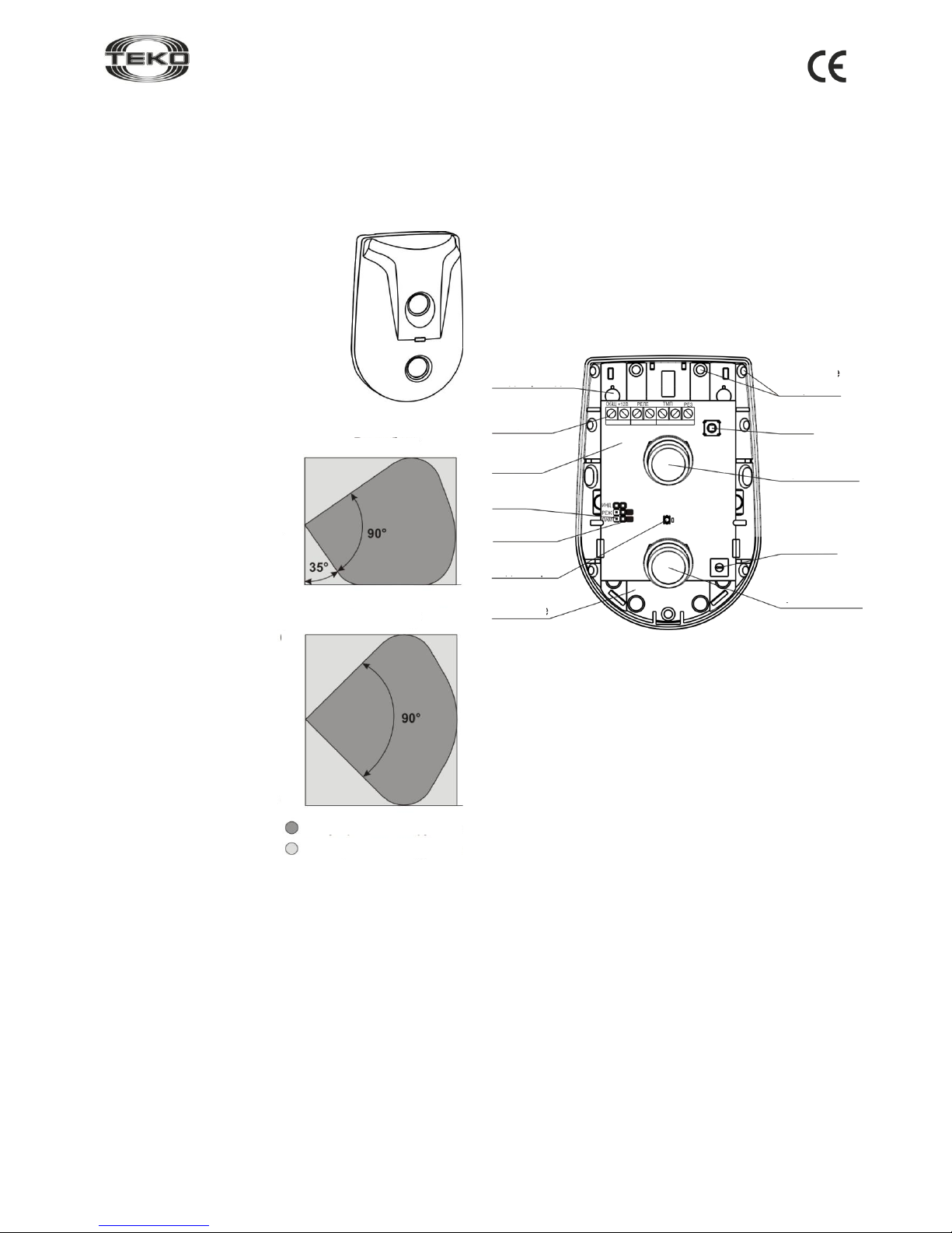
2.2 Schematics of the detection zone are shown in Fig. 2.
Note – The US-channel de-
tection zone depends on a
specific room: some objects
absorb or reflect ultrasound,
thus distorting the detection
zone.
3 Specifications
Technical Parameters of US-channel
Intrusion detection range, m, min................................................... 10
Confident detection area angle
in horizontal and vertical plane, о ............................................ 90
Operating frequency, kHz ....................................................... 25
Movement speed detection range, m/s................ from 0.3 to 2.0
Recommended mounting height, m ....................................... 2.2
General Technical Parameters
Power supply voltage, V .......................................... from 8 to 15
Current consumption, mA, max .............................................. 25
Readiness time, s, max .......................................................... 20
Permissible current through relay contacts, А, max............. 0,08
Permissible voltage on relay contacts, V, max ..................... 100
Resistance of the circuit, included in the alarm loop
in standby mode, Ohm ........................................................... 16
Overall dimensions, mm, max ............................... 106.5×72×38
Weight, kg, max ................................................................... 0.08
Operating Conditions
Temperature range, °С ................................. from -10 up to +50
Relative air humidity, % ...................................... up to 95 at + 35 °С
no moisture condensation
4 Delivery Set
Ultrasonic volumetric detector Astra-642 ........................... 1 pcs.
Bracket ............................................................................... 1 pcs.
Screw 2,9х25 (or 2-3x30) ................................................... 2 pcs.
Dowel 5х25 ........................................................................ 2 pcs.
Sealing material ................................................................. 1 pcs.
User Instruction ................................................................ 1 copy.
5 Structure
Fig. 3
Structurally, the detector is a unit comprised of a base and a
removable cover.
The unit houses a printed circuit board with radio elements,
screw terminal blocks for external connections, ultrasonic
transmitter and receiver (Fig. 3).
A switch installed on the printed circuit board generates a
“Tampering” notification when the cover is detached by open-
ing the ТМР circuit (irrespective of whether or not the detector
power supply is switched on).
The following indicators are mounted on the printed circuit
board: red – for detector status monitoring, blue – for interference indication.
The US-channel detection range can be adjusted using the
US-channel range controller.
Fig. 1
Fig. 2
Side view
Top view
Confident detection area
Probable detection area
10m
2.2m
10m
6m
0
6m
Wire
insertion holes
Mounting
holes
Screw
terminals
Tamper
Switch
PCB
Ultrasonic
transmitter
Plugs
Jumpers
US-channel
range
controller
Indicators
Ultrasonic
transmitter
Base
Cover removed
Page 2
Rev. 642-v2_6_en
2
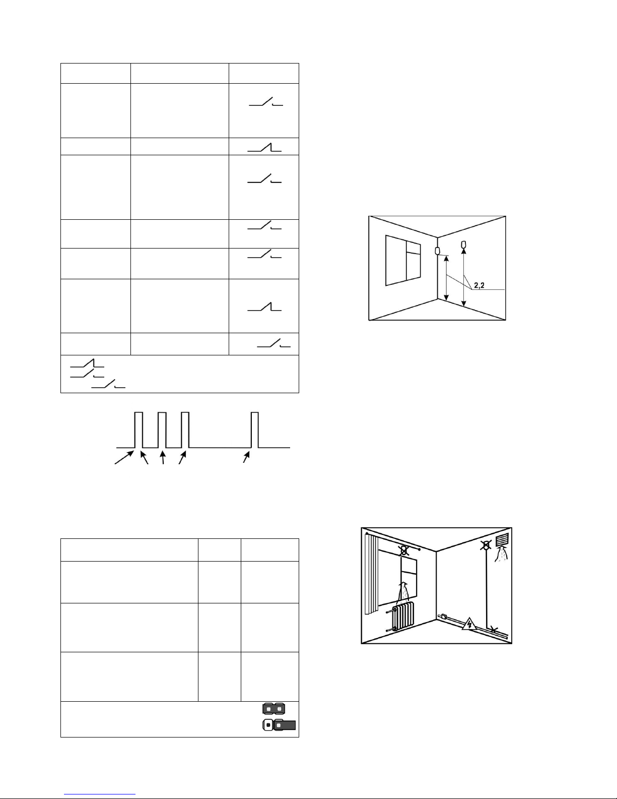
6 Information Capacity
Table 1 – Notification – Indicator and relay
Type of
notification
Indicator
Relay
Detector
standby mode
start
Blinks red and blue
alternatively after
power up.
Duration – up to 20 s
For up to 20 s
Norm
Not lit
Alarm
Lights up red once for
4 s if a person is detected moving in the
detection area (if indication is permitted)
For 4 s
Alarm in “Alarm
memory” mode
Fig. 4
For 4 s
Failure
Lights up red until failure is eliminated
Until failure elimination
Interference
Blinks blue for as long
as interference is
present (if indication is
permitted)
Tampering
Not lit
ТМП
" " –relay is closed,
" " –relay is open,
"ТМП " – ТМР circuit is open
Fig. 4
7 Operating Modes
Table 2 – Operating modes and settings
Operating mode
Plug
Jumper
position
Indication ON
Indication OFF
ИНД
+
–
High detectability
Normal detectability
РЕЖ
+
–
“Alarm memory” ON
“Alarm memory” OFF
ПАМ
+
–
"+" - jumper is installed on both plug pins
"–" - jumper is removed (or installed on one plug pin)
The “Alarm memory” mode allows registering the fact
and number of zone violations in prortected area, and is
reflected in corresponding notification .
The mode is activated in 1 minute after installation of ПАМ
plug or in 1 min. after starting of detector stand-by mode with
jumper installed previously on ПАМ plug. “Alarm” notification
is indicated in 1 min. after violation of protected area. To
switch the mode off and reset indication, remove jumper from
ПАМ plug or switch power off.
8 Installation and Pre-starting Procedure
8.1 Works on installation, mounting, maintenance and
operation of detector should be performed by only qualified
persons.
8.2 After transportation in conditions differing from those of
operation keep detector unpacked under supposed operation
conditions for at least 4 hours.
8.3 Selecting a Location
8.3.1 Recommended mounting height
8.3.2 The detector shall be mounted on load-bearing, vibra-
tion-free structural elements.
8.3.3 Alarm loop and power circuit wires shall not be located near
power cables.
8.3.4 This detector type allows mounting several detectors in
the same room. Detectors shall be placed not closer than 5
m from each other.
8.3.5 It is not permitted to operate the detector in a room with
noise levels exceeding 75 dB.
8.3.6 Do not mount the detector near curtains (blinds) and
other object which may move when air currents move through
the room.
8.3.7 When a room is being protected, it is recommended to
close doors and ventilation windows, switch off fans, air conditioners and other possible sources of strong air currents, and
make sure there are no animals and insects in the room.
8.3.8 Non-recommended mounting locations
m
Indication is
ON
Indication
Is OFF
Start of
indication
Number of alarm
events (up to 3)
Reiterated indication
0.5s 0.5s 0.5s
1s
1s
4s
Page 3

Rev. 642-v2_6_en
3
8.4 Installation Procedure
Step-1
Push out cover lock from
base slot.
Remove cover
Step-2
Unbend hook on the base.
Remove PCB
Step-3
Press out blanks of selected wire holes
Step-4 Choose mounting option: a, b or c
Step-5а
WALL-MOUNTED
Step-5c
BRACKET-MOUNTED
Press the slot blank for
bracket mounting
Step-5b
CORNER-MOUNTED
Step-6a,b
Bring the base against a wall
at a required height and mark
the wall.
The detector base shall be
positioned in strict
accordance with item 4a
figure
Step-6c
Bring the bracket against
a place you want to
mount the detector on
and mark the mounting
holes.
Mount the bracket on a
wall or on the ceiling
Mounting holes
Step-7a,b
Pull power supply and
alarm loop wires
through the dedicated
wire insertion hole in
the detector base.
Attach the base to the
wall or the corner
Proceed to step 9
Step-7c
Superpose bracket clamp with
base slot of the detector. Drive a
screw partially into the bracket
clamp from the inside of the detector base.
Position the detector as required
and tighten the screw. The
bracket provides for detector
rotation for 87º in horizontal
plane
Step-8
Pull power supply and alarm loop wires through the dedicated wire insertion hole in the detector base
Step-9
Place the printed circuit
board back into the
base, match the PCB
slots with guides on the
base. Press on the PCB
until it clicks in position
Step-10 Connect the wires to detector terminals.
A reserve terminal РЕЗ is provided for connection of a
terminal resistor
Step-11
Seal the wire insertion hole and other holes with the sealing
materials included in the delivery set to prevent air currents
and insects from getting into the detector
Step-12
Install jumper on ИНД and РЕЖ
plugs.
Remove jumper from the ПАМ plug
Step-13
Place the detector cover back
into its position (until it clicks
shut)
Hook
Clamp
Screw
Press out
blanks of
selected
mounting
holes
Press out
blanks of
selected
mounting
holes
c
b
Page 4

Rev. 642-v2_6_en
4
Step-14
Switch on the detector power supply, red and blue indicators
shall alternatively blink for not more than 60 s – it means the
detector is being switched to the standby mode.
If within 30 s after switching to the standby mode the detec-
tor gives the “Interference” notification:
1 Make sure there is no extra emission on the operating fre-
quency of the detector and exclude such emission if
present.
2 Remove any object, vibrating/moving rhythmically by the
detector.
Step-15
Make a TEST-pass through a
protected area with speed of 0.3 m/s
and 2 m/s.
Make sure the “Alarm” notification is
given for every movement (the indicator lights up red for 4 s).
Repeat the TEST-pass in different
directions
Step-16
Push out cover lock from
base slot.
Remove detector cover
Step-17
If required, adjust the US-channel
detection range in accordance with
protected room dimensions using
the US-channel range controller
min – 5 m range;
max – 10 m range
Step-18
Depending on a selected operating
mode, install jumpers on ИНД and
ПАМ plugs
Step-19
Place the detector cover back
into its position (until it clicks
shut)
Step-20
If during alarm system testing in the initial operating period
(1-2 weeks) you receive false “Alarm” notifications due to
specific characteristics of a protected room, remove jumper
from РЕЖ plug
8.5 To provide for reliable operation of the alarm system it is
recommended to test and maintain the detector at least
once a month.
The detector shall be tested in the following way:
- walk through the detection zone;
- make sure that the “Alarm” notification is present on the
control panel and, if indication is permitted, on the detector
indicator (lights up once for 4 s for each movement).
The detector shall be maintained in the following way:
- inspect integrity of the detector body, reliability of contacts
and mounting, clean the detector from any dirt accumulated.
9 Labeling
The following data are shown on the label glued to the body:
- manufacturer trademark;
- detector abbreviated designation;
- firmware version;
- month and year of manufacture (last two digits);
- conformity mark (if the conformity certificate is available);
- bar code, duplicating textual data.
10 EC Conformity Declarations
This product is in conformity with the provisions of:
EMC 89/336/EEC
EN 61000-6-3:2005 Electromagnetic compatibility (EMC) - Part 6-3:
Generic standards - Emission standard for residential, commercial
and light-industrial environments
EN 50130-4/1995 + A1:1998 + A2:2003 + Corrig. 2003 Alarm systems - Part 4: Electromagnetic compatibility - Product family standard: Immunity requirements for components of fire, intruder and
social alarm systems
EN 60950-1: 2001+A11:2004+Corrig.2004 Safety of information
technology equipment
11 Recycling
The detector does not pose any life or health risk to individuals or to
the environment. Once its service life is complete, the detector may
be utilized with no special environment protection measures.
12 Manufacturer Warranties
12.1 Quality Management System meets provisions of ISO 9001-
2011.
12.2 The manufacturer warrants that the detector will meet requirements of technical specifications if a user follows all shipping,
storage, mounting and operating guidelines.
12.3 Guaranteed storage life – 5 years and 6 months from the
manufacture date.
12.4 Guaranteed service life – 5 years from the commissioning, but
not more than 5 years and 6 months from the manufacture date.
12.5 The manufacturer shall repair or replace a faulty detector during the warranty period.
12.6 The warranty becomes void if:
- the user does not follow guidelines of the operating manual;
- the detector is mechanically damaged;
- the detector is repaired by a party other than the Manufacturer.
12.7 The warranty covers the detector only. All equipment manu-
factured by other parties and used with the detector is covered by its
respective warranty.
The manufacturer shall not be responsible for personnel death,
injury, and damage to equipment or other accidental or delibe-
rate losses based on user’s claims that the detector failed to
function properly.
Sales:
Controlex GmbH
Warranty service and
technical support:
ТЕКО-TD
Philosophenweg 31-33
47051 Duisburg, Germany
Phone: +49 (0) 203 / 393 91 188
Fax: +49 (0) 203 / 393 91 189
GSM: +49 (0) 178 / 218 48 22
E-mail: info@controlex.eu
Web: www.controlex.eu
Prospekt Pobedy str. 19
420138 Kazan, Russia
Phone: +7 (843) 261-55-75
Fax: +7 (843) 261-58-08
E-mail: info@teko.biz
support@teko.biz
Web: www.teko.biz
Made in Russia
Top view
Indication OFF
Indication ON
“Alarm memory” OFF
“Alarm memory” ON
c
b
 Loading...