

Page 1
Astra-6 (Volumetric Lens)
Optic-Electronic PIR Motion Detector
Operation Manual
The present operation manual is intended for studying
operation principle, running conditions and maintenance of PIR
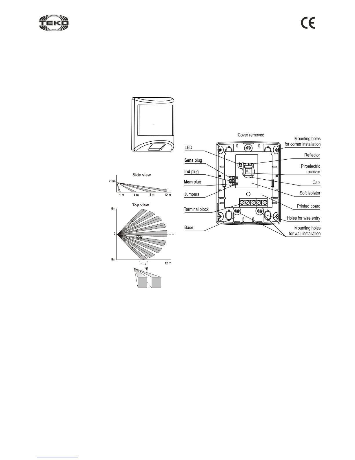
motion detector Astra-6 (hereinafter “detector”) (Figure 1).
The manufacturer reserves the right to make alteration
regarding refinement of the product without prior notification. All
changes will be imported into new edition of the operation
manual.
1 Function
1.1 Detector is intended to detect
unauthorized access into closed
protected area, and to generate an alarm
notification by opening of alarm relay
contacts.
1.2 Power supply of detector is
performed from any direct current source
with nominal voltage 12V and pulsation
amplitude not exceeding 0,1V.
2 Principle of Operation
Operation principle is based on
registration of changes in
thermal emission flux occurring
on crossing by a man of
detection zone consisting of
sensitive zones. Each
sensitive zone consists of two
elementary sensitive zones
(figure 2).
Detector sensitive zones are
formed by Fresnel lens and biareal pyroelectric radiation
reciever.
Pyroelectric reciever sends
electric signal to
microcontroller, which in its
turn generates an “Alarm”
notification in accordance with
pre-set algorithm by opening
optoelectronic relay circuit.
Figure 2
3 Specifications
Technical Parameters of Optical Channel
Detection range, m, not exceeding ............................................... 12
Detection area volume
with viewing angle in horizontal plane ............................ 12×12
Range of detected
moving speed, m/s ....................................... from 0,3 up to 3,0
Resistance to ambient light, lx, not less than ................... 6500
Recommended height of installation, m ........ from 2,4 up to 2,5
General Technical Parameters
Power supply voltage, V ................................... from 8 up to 15
Current consumption in stand-by mode and
in “Alarm” mode, mA, not exceeding .................................... 15
Relay contacts permissible current, A, not exceeding ....... 0,08
Permissible voltage on relay
contacts, V, not exceeding ................................................. 100
Resistance of circuit connected to signaling zone,
in stand-by mode, Ohm ...................................... from 6 up to 8
Overall dimension, mm, not exceeding..................... 75×58×48
Weight, kg, not exceeding ............................................... 0,051
Operating Conditions
Temperature range, °C ................................ from -30 up to +50
Relative air humidity,% ................................... up to 95 at + 35 °С
without moisture condensation
4 Delivery Set
PIR motion detector Astra-6
..................................................
1 pcs
Screw 2-3x30 ................................................................... 2 pcs
Dowel 5x25 ...................................................................... 2 pcs
Sealing material................................................................ 1 pcs
User Instruction .............................................................. 1 copy
5 Structure
Figure 3
Detector is designed as a unit consisting of a base and
removable cover. Printed circuit-board with radioelements and
screw terminal block for outside connections is mounted
inside the unit (figure 3).
Detector operability indicator for operation capability control is
installed on the printed board.
From the inner side of the detector’s cover there is a fixing
element installed, clamping and fixing the lens.
Pyroelectric detector is equipped with a cap with reflector
which forms short-range detection zone.
ATTENTION! It is forbidden to operate detector without a
cap.
Figure 1
Page 2
6-v6_4_en
2
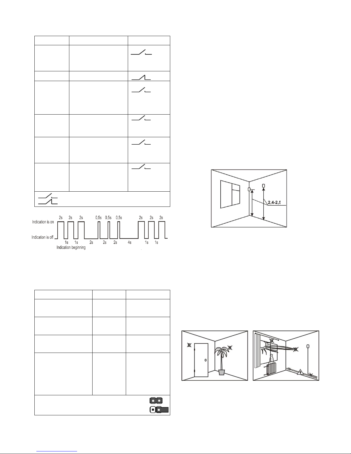
6 Information Capacity
Table 1 – Events and notifications to indicator and relay
Event type
Indicator
Relay
Starting of
detector
stand-by
mode
Flashes 1 time per 1s
after powerup.
Duration up to 60s
During up to
60s
Norm
Not lit
Alarm
Lights up 1 time for 4s
at detection of man
movement in detection
zone (when indication is
enabled)
Relay opens for
4s
Alarm in the
“Alarm
memory”
mode
Figure 4
Relay works in
common mode
Alarm during
test-pass
Lights up 1 time for 2s
at detection of man
movement in detection
zone
Relay opens for
2s
Failure
Keeps lighting until failure elimination
Relay is open
until failure elimination
relay is open,
relay is closed
Figure 4
7 Operation Modes
Table 2 – Operating modes and settings
Operation mode
Plug name
Jumper position
High detectability
Normal detectability
Sens
+
–
Indication is ON
Indication is OFF
Ind
+
–
“Alarm memory” is ON
“Alarm memory” is OFF
Mem
+
–
TEST-pass
(Switches ON for 8
min.)
Ind
For a short moment (for 2-3s)
change jumper
position on the
plug Ind during
starting of detector working mode
“+” - jumper is installed on both plug pins
“-” – jumper is removed (or installed on one plug pin)
The “Alarm memory” mode allows registering the fact
and number of zone violations in prortected area, and is
reflected in corresponding notification .
The mode is activated in 1 minute after installation of
Mem plug or in 1 min. after starting of detector stand-by mode
with jumper installed previously on Mem plug. “Alarm”
notification is indicated in 1 min. after violation of protected
area. To switch the mode off and reset indication, remove
jumper from Mem plug or switch power off.
TEST-pass allows revealing precise location of sensitive
zones formed by the lens. On expiry of 8 min the detector
automatically starts its stand-by mode.
8 Installation and Pre-starting Procedure
8.1 Works on installation, mounting, maintenance and
operation of detector should be performed only by quaified
persons.
8.2 After transportation in conditions differing from those of
operation keep detector unpacked under supposed operation
conditions for at least 4 hours.
8.3 Selection of Installation Place
8.3.1 Recommended height of installation
8.3.2 In capital buildings it is recommended to install
detector on bearing wall.
8.3.3 In light metalwork buildings one should avoid to install
detector directly on the wall, it is recommended to install
detector on bearing carriers.
8.3.4 Wires of signaling zones and power supply circuits should
be located far from power cables.
8.3.5 It is recommended to close all doors, air-vents, switch
off fans, air-conditioners and other sources of intense air flows
in the room during protection period.
8.3.6 It is not recommended to install detector in the
following places.
m
number of alarm
events (up to 3)
Reiterated indication
Page 3

6-v6_4_en
3
8.4 Installation Procedure
Step-1
Push out cover lock from
base slot.
Remove cover
Step-2
Unbend hooks on base
Remove circuit board
Hooks
Step-3a
Installation on the wall
Step-3b
Installation in the
corner of the room
Step-4
Make marking on the wall at the required height applying
the base to installation surface.
Detector base should be positioned strictly as per
figure of the step 3a.
Step-5
There is a possibility to
install detector using
universal or swinging
bracket, for which purpose
it is required to push out
end cap of lead on the
base.
Note – Bracket is supplied
separately
Step-6
Lead wires from power
supply source and
signaling zones through
wire insertion hole on the
base.
Fix the base on the wall or
in the corner of the room.
Step-7
Install printed circuit board
on its place
Step-8
Connect wires led to detector
terminals
For convenience in
connection of terminal
resistor, the additional
terminal RES is provided
Step-9
Using sealing material of distribution kit seal hermetically
wire insertion hole and other holes to protect detector from
air and insects ingress
Step-10
Install jumper on Ind plug and
Sens plag.
Remove jumper from Mem plug.
Step-11
Power detector up, indicator flashes 1 time per 1 s. during
60s – starting of detector working mode.
Step-12
During starting of detector working
mode remove for a short period of
time (2-3s) and install back jumper of
Ind plug connector (TEST-pass
mode switches on for 8min)
Step-13
Install detector cover on its
place (until the click)
Step-14
To detect sensitive zones carry
out TEST-pass in the secured
zone with the speed of 0,3 m/s.
On detection (indicator is lighted
for 2s) one should stop, mark this
position, then make step back and
continue moving.
Repeat TEST-pass inversely.
Sensitive areas formed by lens will
be in the middle of the marked
positions.
Step-15
Push out cover lock from
base slot.
Remove detector cover
Extrude plugs
of selected
mounting
holes
Extrude plugs
of selected
mounting
holes
For universal
bracket
For swinging
bracket
С
A
B
С
A
B
Page 4

6-v6_4_en
4
Step-16
Install jumpers on Ind plug and Mem
plug depending on selected operating
mode.
Step-17
Install detector cover in its
place (until the click)
Step-18
If during alarm system testing in the initial operation period
(1-2 weeks) there are generated false “Alarm” notifications
connected with peculiarities of the secured room, one
should remove jumper from Sens plug.
8.5 To provide fail-safe operation of alarm system it is
recommended to carry out testing and maintenance of the
detector at least 1 time per month.
Testing should be carried out as follows:
- Perform moving through detection zone;
- Check output of "Alarm” notification on control panel and on
indicator if indication is enabled (indicator lights on 1 time for
4s at every movement).
Maintenance should be performed as follows:
- inspect integrity of the detector’s body, reliability of contact
connections, detector fixation; clean detector from
contamination.
9 Labeling
On a label attached to the case are indicated:
- abbreviated marking of the detector;
- firmware version;
- month and year (last two digits) of manufacture;
- conformity mark (if certificate is available);
- barcode, duplicating text information
10 EC Conformity Declarations
This product is in conformity with the provisions of:
EMC 89/336/EEC
EN 61000-6-3:2005 Electromagnetic compatibility (EMC) - Part 6-3:
Generic standards - Emission standard for residential, commercial
and light-industrial environments
EN 50130-4/1995 + A1:1998 + A2:2003 + Corrig. 2003 Alarm systems
- Part 4: Electromagnetic compatibility - Product family standard: Immunity requirements for components of fire, intruder and social alarm
systems
EN 60950-1: 2001+A11:2004+Corrig.2004 Safety of information technology equipment
11 Recycling
Detector is not dangerous for life and health of people and is safe for
environment, after termination of service life it should be recycled
without special environment protective measures.
12 Warranty
12.1 Quality Management System meets provisions of ISO 9001-
2011.
12.2 The manufacturer provides requirements compliance of detector
in condition of observance of technical requirements concerning
transportation, storage, mounting and operating the detector.
12.3 The storage warranty time is 5 years and 6 months from the date
of manufacturing.
12.4 The operation warranty time is 5 years from the date of operation
start-up but no longer than 5 years 6 months from the date of manufacturing.
12.5 The manufacturer commits to replace or repair the product during the warranty period.
12.6 The warranty does not come into effect in following cases:
-operation manual is missing;
-mechanical damage of the product;
-repair of the detector by any other party except the manufacturer.
12.7 This warranty applies to the detector only, not to equipment of
third part manufacturers used with the detector jointly.
12.8 User should keep in mind that correctly installed signaling system serves to decrease the risk of such events as larceny, robbery or
fire, but not to avoid them at all.
The manufacturer bear no responsibility for death, injury,
damage of property or any other kinds of accidental or
premeditated damages, based on user’s statement that device
failed to implement its function.
Sales:
Controlex GmbH
Warranty service and
technical support:
ТЕКО-TD
Philosophenweg 31-33
47051 Duisburg, Germany
Phone: +49 (0) 203 / 393 91 188
Fax: +49 (0) 203 / 393 91 189
GSM: +49 (0) 178 / 218 48 22
E-mail: info@controlex.eu
Web: www.controlex.eu
Prospekt Pobedy str. 19
420138 Kazan, Russia
Phone: +7 (843) 261-55-75
Fax: +7 (843) 261-58-08
E-mail: info@teko.biz
support@teko.biz
Web: www.teko.biz
Made in Russia
 Loading...