

Page 1
Astra-421 Ver. RF
Wireless Optoelectronic Smoke Detector
Operation Manual
This operation manual is intended for studying principle of
operation, correct use, operating conditions and maintenance of
the wireless optoelectronic smoke detector «Astra-421» ver.RF
(hereinafter «detector») (figure 1).
The manufacturer reserves the right to make alteration regarding refinement of the product without prior notification. All
changes will be imported into new edition of the operation manual.
1 Function
1.1 The detector is intended for
detecting fire followed by smoke
spreading, forming and transmitting «Fire» notification to the receiver «Astra-RVA» (hereinafter
«receiver») of wireless intrusion/fire
detection and alarming system Ob-
server-1.
1.2 The detector supports 3 operat-
ing frequencies.
1.3 Electric power is supplied by a
lithium-thionyl-chloride battery cell
standard size AA, voltage 3,6 V
(included in delivery set).
2 Principle of Operation
The principle of operation of the detector is based on registering infrared radiation (hereinafter IR) that is reflected from
smoke particles in the smoke chamber by a photodetector. Further the electric signal formed by the photodetector is amplified
and sent to microcontroller in order to analyze the smoke density value. The detector generates «Fire» or «Warning» notification in accordance with a specified operating algorithm.
3 Specifications
Detector`s sensitivity, dB/m ................................ from 0,05 to 0,2
Response time, sec., max ......................................................... 5
Detection area, m2, max ........................................................ 110
Installation height, m, max ....................................................... 10
Technical Parameters of Radio Channel
Operating frequency, MHz ................................................ 433,42
Emission power, mWt, max ..................................................... 10
Wireless coverage range*, m, min ......................................... 300
General Technical Parameters
Current consumption:
- with transmitter turned OFF, mA, max............................... .0,05
- with transmitter turned ON, mA, max ................................... .25
Supply voltage, V ................................................. from 2,7 to 3,6
Technical readiness time, s, max…………………………….….60
Standby mode recovery time, s, max ...................................... 60
* Along the line-of-sight. Wireless coverage range is largely dependent
on the design features of construction, the installation location, the interference situation.
Overall dimensions, mm, max
- diameter .............................................................................. 100
- height ..................................................................................... 47
Weight, kg, max .................................................................... 0,12
Battery cell average life time, years, min ................................... 3
Operating Conditions
Temperature range, °С ..................................... from - 10 to + 55
Relative air humidity, % ................................ up to 93 at + 40 °С
without moisture condensation
4 Delivery Set
Wireless optoelectronic smoke detector
«Astra-421» ver. RF ........................................................... 1 pcs
Screw 3,9х32 ...................................................................... 2 pcs
Dowel 6х30 ......................................................................... 2 pcs
Battery cell .......................................................................... 1 pcs
Operation manual ............................................................. 1 copy
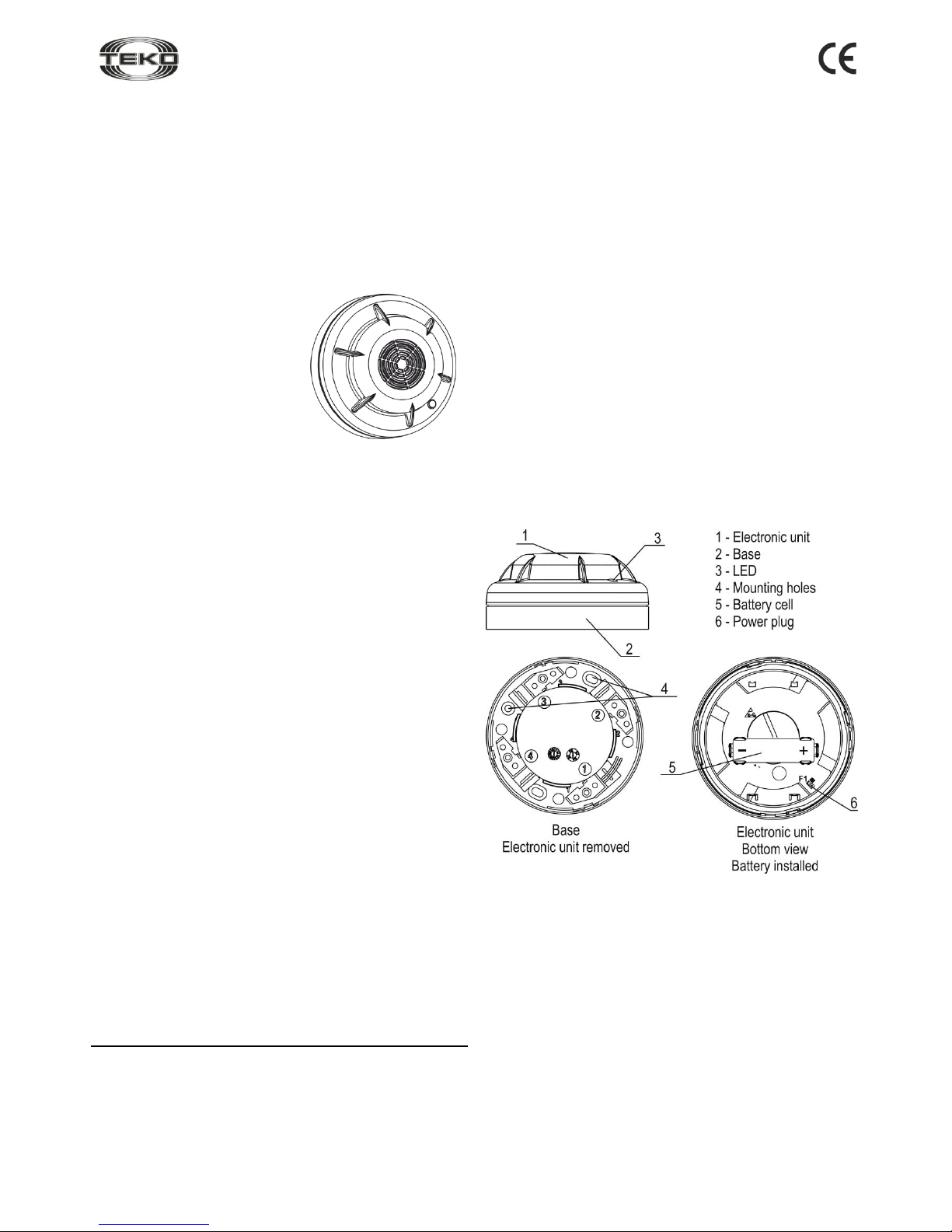
5 Structure
Constructively the detector consists of a removable electronic
unit and a base (figure 2).
Figure 2
Inside the electronic unit is a smoke chamber and printed circuit
board (PCB) with radio elements and photodetector.
Mounted on PCB is a LED for checking the detector`s operability.
The design of the detector provides for its installation on the
ceiling.
Note - It is not recommended to disassemble the electronic unit
of the detector, as it may damage the detector’s tuning.
Figure 1
Page 2
421-rkv16_1_en
2
6 Information Capacity
Table 1- Notification types
Notification
types
LED
Receiver
Standby mode
Lights up for the time of 1-20
sec, then flashes once per 1
sec. Duration is up to 60 sec.
−
Norm
Not lit
+
Fire
Flashes once per 1,5
as the smoke density in the
secure area reaches the operation threshold. Flashes as
long as the smoke is there.
+
Warning
Flashes 2 times per 1 sec
during 5 sec as the smoke
density in the secure area
reaches 75% of the activation
threshold
+
Failure
Flashes 1 time per 3 sec
+
Low supply
voltage
Flashes 2 times successively
once per 10-15 sec, at supply
voltage less than 2,9 V.
+
«+» – notification is generated,
«–» – notification is not generated
Note - In case «Low supply voltage» notification is generated, it
is necessary to replace battery cell within one week.
7 Operation Modes
The detector provides for
«Test» and «Autotest»
operating modes, intended
for testing electronic circuits
of the detector.
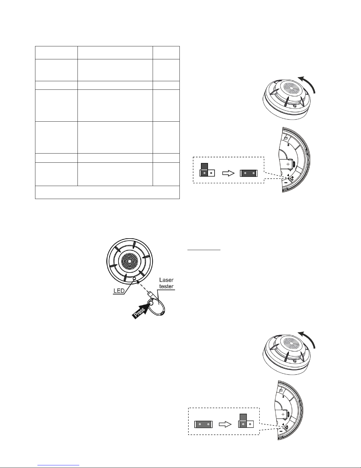
7.1 The «Test» mode is
activated when reading a
coded message by LED sent
from laser tester «Astra-
941» (figure 3).
In 5 sec after reading the
message, the detector must
output the «Fire» notification
- if the detector operation is
normal, or «Failure» - in
case of a failure.
Figure 3
Note - Laser tester «Astra-941» is optional and delivered sepa-
rately.
7.2 The «Autotest» mode is activated by the detector auto-
matically every 24 hours. At that the operation threshold is adjusted depending on the environment and the «Test» mode is
activated. Upon successful completion of the test notification is
not generated. In case of failure, «Failure» notification is
generated.
8 Pre-starting Procedure
8.1 After transportation in conditions differing from those of
operation, keep the detector unpacked for 4 hours in the expected operating conditions.
ATTENTION! Check correspondence of frequency carrier
of the detector and the receiver.
8.2 Running Detector
Attention! Lithium-thionyl-chloride batteries have an effect of
«passivation» to provide the possibility of long-term storage. To
provide battery normal operation after long-term storage, hold
an «activation» procedure.
Step-1
Place the detector on-thespot.
Turn the electronic module
counterclockwise.
Remove the electronic unit
from the detector`s base.
Step-2
Install the battery cell.
Switch the detector ON by installing jumper on power plug.
Step-3
To replace battery:
- switch the detector OFF;
- remove the old one;
- after no less than 20 sec install the new battery.
When installing into detector the battery is automatically
«activated» and checked. The LED lights red (less than 20
sec.)
After checking:
In case the LED flashes 2 times successively with fre-
quency once per 10-15 sec («Low supply voltage»), remove
jumper, close the positive and negative poles of the battery
for 2-3 sec with a piece of wire and repeat switching by installing jumper back after at least 20 sec.
In case the LED flashes with frequency once per 1 sec
(«Standby mode») and notification «Power failure» is not
appears, the battery is considered as useful.
8.3 Registration Procedure
The detector registering in the receiver memory occurs at the
moment of powering up.
Step-1
Place the detector on-thespot.
Turn the electronic module
counterclockwise.
Remove the electronic unit
from the detector`s base.
Step-2
Switch the detector OFF by
removing jumper from
power plug
Page 3

421-rkv16_1_en
3
Step-3
Set the registration mode on a receiver according to procedure described in the «Astra-RVA» operation manual or the
Observer-1(2) system operation manual (available for free
downloading from www.controlex.eu) or Quick Start Guide.
Step-4
Switch the detector ON by installing jumper on two pins of
power plug
Step-5
Make sure the registration procedure is completed according
to procedure described in the «Astra-RVA» operation manual
or the Observer-1 system operation manual (available for
free downloading from www.controlex.eu) or Quick Start
Guide.
Once the registration procedure completed successfully
reassemble the detector.
- superpose the electronic unit and the base.
- rotate the electronic unit until matching the projections of
the electronic unit with the base` grooves.
- press the electronic unit to the base and rotate clockwise
until it stops.
Once the registration procedure failed remove jumper
from the power plug and after at least 20 sec repeat
steps 3-5.
Step-6
After successful registration of the detector, for long term
storage before its installation, it is allowed to switch the detector OFF by removing jumper from power plug.
When installing the detector on-site there is no need to reregister it in the memory of the same receiver, if the memory
of the receiver has not been cleared.
9 Installation
9.1 Selection of Installation Place
9.1.1 The detector is installed on a ceiling.
9.1.2 An area covered by a single detector, maximum distance
between detectors, and between a detector and a wall can be
calculated according to table 2.
Table 2
Secure room
height, m
Average area covered by 1 detector,
m2
Maximum distance, m
between
detectors
from detector to
wall
up to 3,5
up to 85
9,0
4,5
over 3,5 to 6,0
up to 70
8,5
4,0
over 6,0 to
10,0
up to 65
8,0
4,0
9.1.3 If the detector is installed on an inclined ceiling, it must
be mounted at the highest position.
9.1.4 For smoke particles to be able for freely penetrating the
smoke chamber through the grid, it is forbidden to mask the
detector.
9.2 Installation Procedure
Step-1
Place the detector on-the-spot.
Turn the electronic module
counterclockwise.
Remove the electronic unit from
the detector`s base.
Step-2
Switch the detector OFF by removing jumper from power plug
Step-3
Make markings on the
ceiling by using the applied
base.
Fasten the base to the
ceiling.
Step-4
Switch the detector ON by installing
jumper on two pins of power plug.
The LED lights up for 1 to 20 sec,
then flashes once per 1 sec during 60
sec (Standby mode).
Step-5
Mount the electronic unit onto the fastened base:
- superpose the electronic unit and the base.
- rotate the electronic unit until matching the projections of
the electronic unit with the base grooves.
- press the electronic unit body to the base and rotate clockwise until it stops.
Page 4

421-rkv16_1_en
4
Step-6
Activate the «Test» mode:
- press the red button on the
laser tester;
- direct a laser ray at the LED;
- irradiate the LED during 1 sec.
In 5 sec. make sure the «Fire»
report on the detector`s LED
(double blink per 1 sec. for 1317 sec.) and on the red LED of
the receiver (double blink per 1
sec) is appeared.
10 Maintenance
To ensure the alarm system reliable operation, testing and
maintenance of the detector is recommended.
Testing should be carried out as follows:
Check absence/output of the «Failure» notification on the
LED at least once a week;
Check the detector operability by using a laser tester at
least once in 3 months (by the method 9,6 step 6);
Clean the detector’s smoke chamber at least once in 3
months as follows:
1) Remove the electronic unit from the detector`s base
2) Switch off the detector by removing jumper from power plug
3) Clean by compressed air.
4) Switch on the detector by installing jumper on two pins of
power plug.
5) Wait for 60 sec (standby recovery time).
6) Activate the «Test» mode according to p.9.2 step 6.
7) Mount the electronic unit onto the fastened base.
11 Labeling
On a label attached to the case are indicated:
- trademark of the manufacturer;
- abbreviated marking of the detector;
- firmware version;
- frequency carrier;
- month and year (last two digits) of manufacture;
- conformity mark (if certificate is available);
- barcode, duplicating text information.
12 EC Conformity Declarations
This product is in conformity with the provisions of:
R&TTE Directive 1999/5/EC, Article 10.5;
EN 60950: 2001 Safety of information technology equipment;
EN 50371 Generic standard to demonstrate the compliance of lowpower electronic and electrical apparatuses with the basic restrictions
related to human exposure to electromagnetic fields (10 MHz - 300
GHz) – General public;
EN 301489-17 V1.1.1 (09-2000) Electromagnetic Compatibility and
radio spectrum Matters (ERM); Electromagnetic Compatibility (EMC)
standard for radio equipment and services; Part 17: Specific conditions
for wideband data Hiperlan equipment;
EN 300220-1 V1.3.1 (2000-09) Electromagnetic compatibility and Radio
spectrum Matters (ERM); Short range devices; Technical characteristics and test methods for radio equipment to be used in the 25 MHz to 1
000 MHz frequency range with power levels ranging up to 500 mWt;
Part 1: Parameters intended for regulatory purposes.
Construction of the detector provides for protection class IP41.
13 Recycling
13.1 Detector is not a danger to life, human health and the environment. On expiry of its lifetime recycling is done without taking special
measures to protect the environment.
13.2 Recycling of battery cells should be done by delivering the used
cells to a trading organization, service centre, manufacturer, or to an
organization accepting used batteries.
14 Warranty Terms
14.1 The manufacturer guarantees the compliance of the detector to
specifications if the user observes required conditions of transportation,
storage, installation and operation.
14.2 The storage warranty period is 5 years and 6 months from the date
of manufacture.
14.3 The operation warranty period is 5 years from the date of putting
into operation but no longer than 5 years 6 months from the date of
manufacturing.
14.4 The manufacturer guarantees replacement or repair of the product
during the warranty period.
14.5 The warranty doesn’t come into effect in the following cases:
- not adherence to instructions of the operation manual;
- mechanical damage of the detector;
- repair of the detector by any third-party service apart from the manufacturer.
14.6 Warranty applies to the detector only. All equipments from thirdparty manufacturers used in conjunction with the device, including batteries, are subject to their own warranty terms and conditions.
The manufacturer bears no responsibility for death, injury, property damage or other incidental or premeditated loss based on the
user's statement that the detector has failed to implement its functions.
Sales:
Controlex GmbH
Warranty service and
technical support:
ТЕКО-TD
Philosophenweg 31-33
47051 Duisburg, Germany
Phone: +49 (0) 203 / 393 91 188
Fax: +49 (0) 203 / 393 91 189
GSM: +49 (0) 178 / 218 48 22
E-mail: info@controlex.eu
Web: www.controlex.eu
Prospect Pobedy str. 19
420138 Kazan, Russia
Phone: +7 (843) 261-55-75
Fax: +7 (843) 261-58-08
E-mail: info@teko.biz
support@teko.biz
Web: www.teko.biz
Made in Russia
 Loading...