

Page 1
Astra-361 Version RF
Wireless Water Leak Detector
Operating Manual
Rev. 361rk-v1_0_en
The present operation manual is intended for studying operating principle, correct usage, storage and maintenance of wireless water leak detector Astra-361ver. RF (hereinafter referred
to as “detector”) (Fig. 1).
The manufacturer reserves the right to make alteration regarding
refinement of the product without prior notification. All changes
will be imported into new edition of the operation manual.
1 Function
1.1 The detector is designed for detection
of water leak events (except for distilled water), forming an “Alarm” notification and
sending it to receiver Astra-RVA (hereinafter “RVA”) of wireless intrusion and fire detection and alarming system Observer I.
1.2 The detector supports three operating
frequencies.
1.3 The detector is powered by a battery of
CR2450 type (voltage – 3.0 V) or batteries
of comparable characteristics and design.
2 Specifications
Technical Parameters of Radio channel
Operating frequency, MHz ................................................ 433.42
Wireless coverage range, m*, min ......................................... 300
Emission power, mWt, max ..................................................... 10
General Technical Parameters
Current consumption, mA, max:
- transmitter OFF ............................................................... 0.015
- transmitter ON ...................................................................... 25
Power supply voltage, V ..................................... from 2.25 to 3.0
Overall dimensions, mm, max ................................. 64 46 22
Weight, kg, max ................................................................... 0.05
Average battery service life, years, min .................................... 2
Operating Conditions
Temperature range, °С ......................................... from +5 to +50
Relative air humidity, % .................................. up to 93 at + 40 °С
no moisture condensation
__________________________________
* Along the line-of-sight. Wireless coverage range is largely dependent
on the design features of construction, the installation location, the interference situation.
3 Delivery Set
Wireless water leak detector Astra-361ver. RF ................. 1 pcs.
Battery ............................................................................... 1 pcs.
Operating manual .......................................................... ..1 copy.
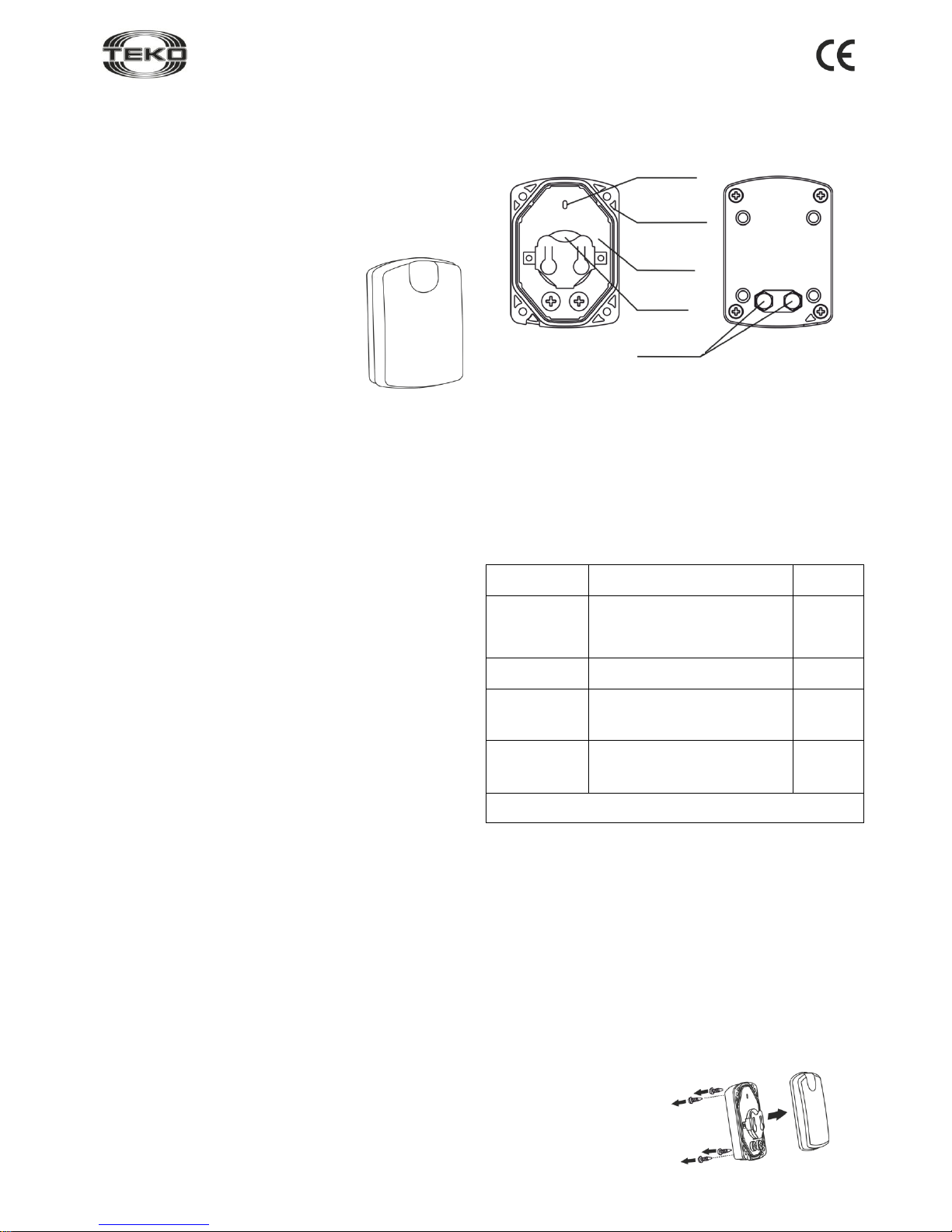
4 Structure
Fig. 2
Structurally, the detector is designed as a unit consisting of a
base and a removable cover (Fig. 2). The cover is attached to
the base with screws.
The unit houses a printed circuit board with radio elements.
An indicator mounted on the circuit board provides for detector
operability supervision.
Contact pads are located on the detector body.
5 Information Capacity
Table 1 – Notifications processed by indicator and RVA
Notification
type
Indicator
RVA
Starting detector to standby
mode
Lights once for 0.5 s
after power up
-
Norm
Not lit
+
Alarm
Lights once for 0.2 s when external contact are closed (shorted) by water
+
Low supply
voltage
Blinks 3 times every 25 s when
the battery charge drops below
2.5
-
0.1
V
+
"+" – the notification is given, "– " – the notification is not
given
Note – When “Low supply voltage” notification appears, replace the battery within a week.
6 Pre-starting Procedure
6.1 After transportation in conditions differing from those of
operation keep detector unpacked under supposed operation
conditions for at least 4 hours.
WARNING! Check compliance of operating frequen-
cies of detector and receiver.
6.2 Registering the detector in the receiver memory
Detector is registered at the moment of powering up.
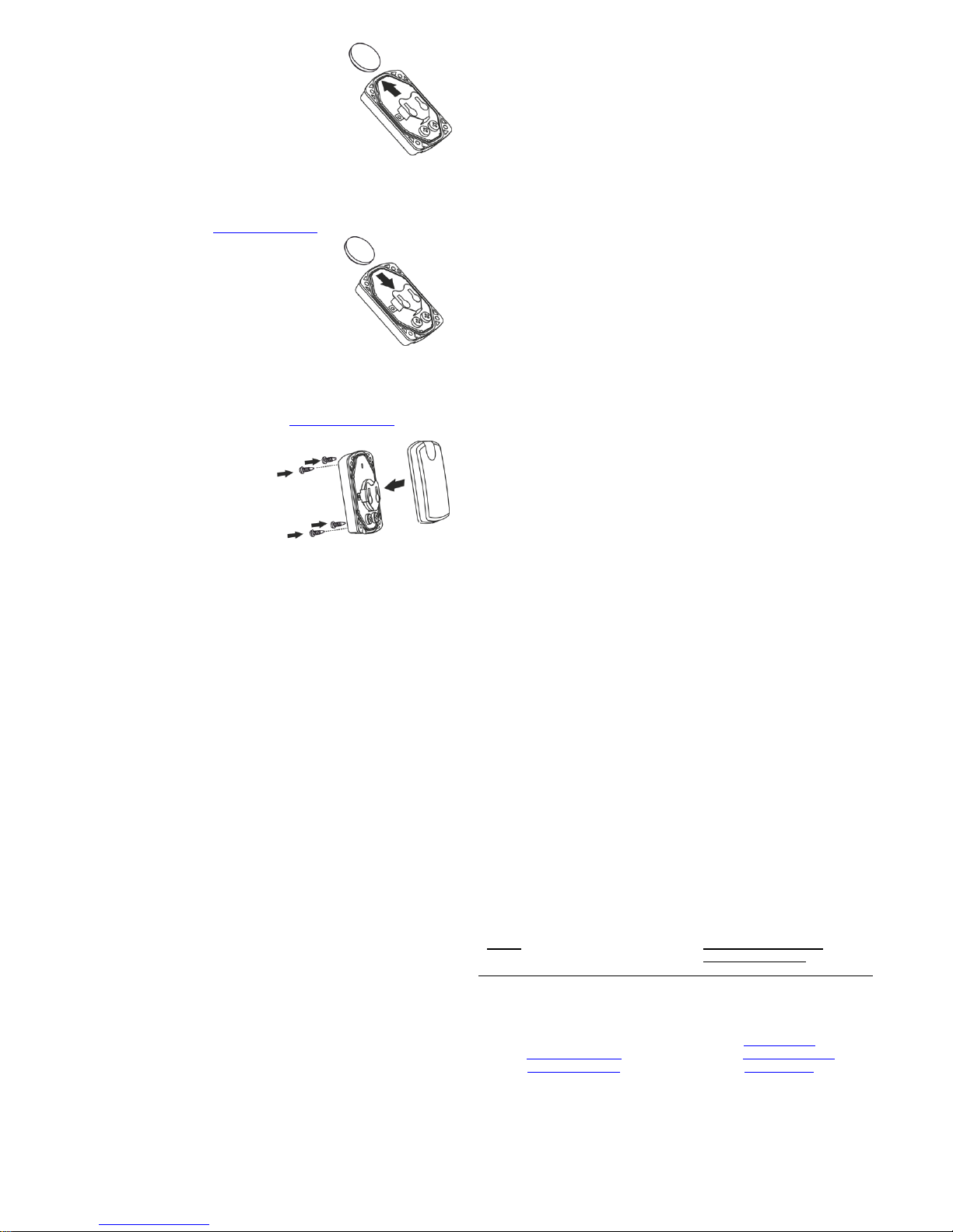
Step-1
Unscrew the screws and
remove the detector cover
Fig. 1
Base
Printed
circuit board
Battery
Contact
pads
Page 2
Rev. 361rk-v1_0_en
2
Step-2
Remove the battery, if installed
Note – Wait at least 40 s before installing
the battery back into the detector. If you
have no time to wait, short plus-minus
contacts of the battery holder using a
screwdriver.
Step-3
Set the registration mode on a receiver according to procedure described in the «Astra-RVA» operation manual or
the Observer I system operation manual (available for free
downloading from www.controlex.eu) or Quick Start Guide.
Step-4
Install the battery; the indicator
lights up for 0.5 s.
Step-5
Make sure the registration procedure is completed according to procedure described in the «Astra-RVA» operation
manual or the Observer I system operation manual (available for free downloading from www.controlex.eu) or Quick
Start Guide.
Once registration procedure completed suc-
cessfully reassemble detector.
In case registration failed repeat steps 2-5
Step-6
After successful detector registering, for long term storage
before its installation, it is allowed to switch the detector
OFF by removing battery.
When installing the detector on-site there is no need to reregister it in the memory of the same receiver, if the memory
of the receiver has not been cleared
7 Installation
7.1 The detector shall be mounted on the floor in the
lowest place of a room where flooding possibility is
monitored (taking into account directions of water flow in
case of burst water conduits or heating system pipelines).
7.2 The detector shall be mounted with the contact pads fac-
ing downwards.
7.3 Check detector operability:
- close (short) the contacts pads (e.g., with a wet cloth),
- make sure “Violation” event is displayed on the RVA indicator or on the display of Astra-812, Astra-812М control panel.
8 Maintenance
To provide for reliable operation of the detector it is recommended to test and maintain the detector at least once a
month in the following way:
- inspect integrity of the detector body;
- check its location;
- check detector operability as described in 7.3;
- clean the detector from any dirt accumulated.
9 Labeling
The following data are shown on the label glued to the body:
- manufacturer trademark;
- detector abbreviated designation;
- firmware version;
- operating frequency;
- month and year of manufacture (last two digits);
- conformity mark (if the conformity certificate is available);
- bar code, duplicating textual data.
10 EC Conformity Declarations
This product is in conformity with the provisions of:
R&TTE Directive 1999/5/EC, Article 10.5;
EN 60950: 2001 Safety of information technology equipment;
EN 50371 Generic standard to demonstrate the compliance of lowpower electronic and electrical apparatuses with the basic restrictions
related to human exposure to electromagnetic fields (10 MHz - 300
GHz) – General public;
EN 301489-17 V1.1.1 (09-2000) Electromagnetic Compatibility and radio spectrum Matters (ERM); Electromagnetic Compatibility (EMC)
standard for radio equipment and services; Part 17: Specific conditions
for wideband data Hiperlan equipment;
EN 300220-1 V1.3.1 (2000-09) Electromagnetic compatibility and Radio spectrum Matters (ERM); Short range devices; Technical characteristics and test methods for radio equipment to be used in the 25
MHz to 1 000 MHz frequency range with power levels ranging up to
500 mWt; Part 1: Parameters intended for regulatory purposes.
Construction of the detector provides for protection class IP41.
11 Recycling
11.1 The detector is not dangerous for life, human health and the environment. On the expiry of product’s lifetime, recycling is done without
taking special measures to protect the environment.
11.2 Used batteries shall be returned to the vendor, the service center,
the equipment manufacturer or to any company collecting used batteries.
12 Manufacturer Warranties
12.1 The manufacturer guarantees the compliance of the detector to
specifications on condition that user observes required conditions of
transportation, storage, installation and operation.
12.2 The storage warranty period is 5 years and 6 months from the
date of manufacture.
12.3 The operation warranty period is 5 years from the date of putting
into operation but no longer than 5 years 6 months from the date of
manufacturing.
12.4 The manufacturer shall repair or replace a faulty detector during
the warranty period.
12.5 The warranty becomes void if:
- the user does not follow guidelines of the operating manual;
- the detector is mechanically damaged;
- repair of the detector by any third-party service apart from the
manufacturer.
12.6 Warranty applies to the detector only. An equipment of third-party
manufacturers used in conjunction with the detector (including batteries) is subject to its own warranty terms and conditions.
The manufacturer bears no responsibility for death, injury, property damage or other incidental or premeditated loss based on
user's statement that the device failed to implement its functions.
Sales:
Controlex GmbH
Warranty service and
technical support:
ТЕКО-TD
Philosophenweg 31-33
47051 Duisburg, Germany
Phone: +49 (0) 203 / 393 91 188
Fax: +49 (0) 203 / 393 91 189
GSM: +49 (0) 178 / 218 48 22
E-mail: info@controlex.eu
Web: www.controlex.eu
Prospect Pobedy str. 19
420138 Kazan, Russia
Phone: +7 (843) 261-55-75
Fax: +7 (843) 261-58-08
E-mail: info@teko.biz
support@teko.biz
Web: www.teko.biz
Made in Russia
 Loading...