

Teknoware TKT67C Series, TKT6748C, TKT6756C, TKT6716C, TKT6732C Installation And Maintenance Instructions Manual
...
VOT2
TKT67C TAPSA CONTROL CENTRAL BATTERY UNIT
FOR EMERGENCY LIGHTING
Installation and maintenance instructions
Made In Finland

2
Table of contents
Table of contents ................................................................................................................ 2
1. Safety instructions ......................................................................................................... 4
2. Package contents and storing ....................................................................................... 4
2.1 Contents of package ............................................................................................................. 4
2.2 Storing ................................................................................................................................... 4
3. Product description ........................................................................................................ 5
3.1 Manufacturer ......................................................................................................................... 5
3.2 Terminology .......................................................................................................................... 5
3.3 Type ....................................................................................................................................... 5
3.4 Explanation of letters (in previous models) ........................................................................ 5
3.5 List of optional features........................................................................................................ 6
3.6 General description .............................................................................................................. 6
3.7 Technical specifications ....................................................................................................... 7
3.8 Directives and standards...................................................................................................... 9
4. Description of operations ............................................................................................ 10
4.1 Purpose of the central battery unit .................................................................................... 10
4.2 Circuit outputs .................................................................................................................... 10
4.3 Circuit board settings ......................................................................................................... 10
4.4 Parallel connection of output circuits ............................................................................... 10
4.5 Control unit.......................................................................................................................... 11
4.5.1 Individual luminaire monitoring test with basic settings ................................................................... 11
4.5.2 Circuit monitoring luminaire test with basic settings ........................................................................ 11
4.6 Operation of the central battery unit .................................................................................. 12
4.7 Normal Status ...................................................................................................................... 12
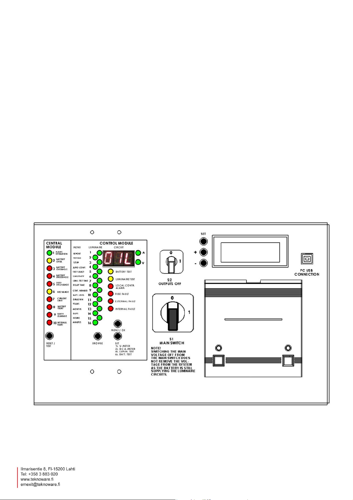
4.8 Central module panel .......................................................................................................... 13
4.9 Control Module panel luminaire monitoring LED’s and menu settings .......................... 15
4.10 Control Module panel test functions and alarms ............................................................ 21
4.11 Buttons .............................................................................................................................. 23
5. System planning and installation ................................................................................ 24
5.1 System planning ................................................................................................................. 24
5.1.1 Luminaire-specific addressable monitoring ..................................................................................... 24
5.1.2 Circuit monitoring ............................................................................................................................. 24
5.2 System installation ............................................................................................................. 24
5.2.1 Parts layout ...................................................................................................................................... 26
5.2.2 Circuit wiring in parallel connection ................................................................................................. 27
5.2.3 DIP switch settings in circuit boards ................................................................................................ 28
5.3 Commissioning ................................................................................................................... 29
5.3.1 Setting of battery type and capacity ................................................................................................. 29
5.3.2 Forced charging of the batteries ...................................................................................................... 30
5.3.3 Checking the luminaire circuits one at a time .................................................................................. 30
5.3.4 Configuration .................................................................................................................................... 30
VOT 2; Rev 1.2; EN; 09.07.2013
TKT67C – Installation and maintenance

3
6. Maintenance .................................................................................................................. 31
6.1 Replacing the batteries ....................................................................................................... 31
7. Disposal ......................................................................................................................... 32
8. Optional Features ......................................................................................................... 32
8.1 LCD display functions ........................................................................................................ 32
8.1.1 Button functions ............................................................................................................................... 32
8.1.2 LCD content ..................................................................................................................................... 33
8.1.3 LCD menu tree ................................................................................................................................. 33
8.1.4 Test history ...................................................................................................................................... 33
8.1.5 Battery test history ........................................................................................................................... 34
8.1.6 Error log ........................................................................................................................................... 35
8.1.7 Setup ................................................................................................................................................ 35
8.1.8 External USB connection ................................................................................................................. 36
8.2 Printer .................................................................................................................................. 37
8.2.1 Language selection of the printer (TKT67..CD) or optional feature TST6731 ................................. 37
8.2.2 Printing out test reports .................................................................................................................... 37
APPENDIX 1: Report Layout ............................................................................................ 38
APPENDIX 2: Mechanical dimensions ............................................................................ 39
APPENDIX 3: Connection alternatives for batteries ...................................................... 40
APPENDIX 4: Circuit diagram with 3-phase input ......................................................... 41
APPENDIX 5: Menu selections ........................................................................................ 54
© Copyright 2013 Teknoware Oy – We reserve the right to make modifications without notice
VOT 2; Rev 1.2; EN; 09.07.2013
TKT67C – Installation and maintenance
4
WARNING
There is always dangerous voltage level in the output circuits and inside the central battery unit if
the central battery unit is switched ON. Chancing the main switch to 0 –position will NOT make
the central battery unit de-energized. The central battery unit and the battery housing can be
opened only by electrically skilled person.
Device must be made de-energized before any maintenance or repair work. Remove the battery
fuses and set the main switch to OFF position.
1. Safety instructions
Read before installing the product.
This manual contains important information that must be followed during the installation and maintenance of
the central battery unit and the batteries. Installation of this device is allowed only to a person who has the
required permissions and qualifications.
National regulations for electric installations and building codes must be observed in the placing of the central
battery unit.
In the installation of batteries, constituted regulations must be observed.
2. Package contents and storing
2.1 Contents of package
The package contains a central battery unit of TKT67XXC series.
Store the package sheltered from the rain.
Do not place anything on top of the package.
NOTE: The package may contain sealed lead acid batteries that contain large quantities of energy and
may short circuit, if stored inappropriately. This must be considered when storing the package.
2.2 Storing
If you do not install the unit and batteries immediately, note the following:
Store the unit in a dry place, protected from humidity.
Store the unit and the batteries in the recommended storing temperature of +10 …+30C.
If the batteries are stored for a longer period of time, they must be recharged every 6 months
for at least 12 hours at a time.
TKT67C – Installation and maintenance
VOT 2; Rev 1.2; EN; 09.07.2013
5
Term
Explanation
Control
Automatic testing
Maintained
Continuously active
Non-maintained
Active only during voltage interruptions
Model
Maximum number of circuits
Input Voltage
TKT6716C(N)
16
220-240 V AC 50/60Hz 3~
TKT6724C(N)
24
220-240 V AC 50/60Hz 3~
TKT6732C(N)
32
220-240 V AC 50/60Hz 3~
TKT6740C(N)
40
220-240 V AC 50/60Hz 3~
TKT6748C(N)
48
220-240 V AC 50/60Hz 3~
TKT6756C(N)
56
220-240 V AC 50/60Hz 3~
Letter
Explanation
C only
Control function
CD
Control and printer
CL
Control and LCD display
CO
Control and LON interface
CDL
Control, printer, and LCD display
CLO
Control, LCD display and LON interface
N
Charging for NiCd batteries
3. Product description
3.1 Manufacturer
Teknoware Oy
Ilmarisentie 8
FI-15200 Lahti
FINLAND
http://www.teknoware.fi/
3.2 Terminology
3.3 Type
3.4 Explanation of letters (in previous models)
TKT67C – Installation and maintenance
VOT 2; Rev 1.2; EN; 09.07.2013
6
TST6731
Integrated Printer TKT67xxC
TST6732
LCD Display Module TKT67xxC
TST6741
Extra Charger Module (adds power taken from mains 3,000 VA)
(1-2 pcs each 3,000 VA, Max each 180 Ah) TKT67xxC
XWT6772
Switched-Maintained Package for 16 circuits each 350 W TKT6716C
XWT6773
Switched-Maintained Package for 24 circuits each 350 W TKT6724C
XWT6774
Switched-Maintained Package for 32 circuits each 350 W TKT6732C
XWT6775
Switched-Maintained Package for 40 circuits each 350 W TKT6740C
XWT6776
Switched-Maintained Package for 48 circuits each 350 W TKT6748C
XWT6777
Switched-Maintained Package for 56 circuits each 350 W TKT6756C
TST6751
IC Interface for 8 circuits each 350 W TKT6708C
TST6752
IC Interface for 16 circuits each 350 W TKT6716C
TST6753
IC Interface for 24 circuits each 350 W TKT6724C
TST6754
IC Interface for 32 circuits each 350 W TKT6732C
TST6755
IC Interface for 40 circuits each 350 W TKT6740C
TST6756
IC Interface for 48 circuits each 350 W TKT6748C
TST6757
IC Interface for 56 circuits each 350 W TKT6756C
TST6722
LON Interface TKT67xxC
TST6701
BACnet Interface TKT67xxC
TST6721
ACM Interface TKT67xxC
TST6724
WebCM/ WebACM Interface TKT67xxC
TST1811E
BCM Interface TKT67xxC
3.5 List of optional features
For more information on optional features, see Chapter 8. Optional Features
Central monitoring options:
3.6 General description
TKT67xxC(N) central battery unit is designed and manufactured according to the standards EN 50171
and EN 60439-1.
In normal situation, the central battery unit operates using a 230 V AC mains voltage, maintaining the
battery charge level and supplying a voltage of 230 VAC to the maintained output circuits. If the mains
voltage is interrupted or it drops below 180 V, the central battery unit switches to battery use. This
connects a voltage of 220 VDC to the non-maintained circuits and the voltage supply to the maintained
circuit switches from 230 VAC to 220 VDC. The battery supply is used as long as the mains voltage
remains unavailable or the battery voltage has dropped to the deep discharge limit (173 V).
In addition to the above mentioned standard functions, the control unit of the central battery unit also
includes the following monitoring, testing and reporting functions:
testing the luminaires either through addressable monitoring or by measuring the circuit
current and by monitoring the condition of the batteries
testing the capacity of the battery
VOT 2; Rev 1.2; EN; 09.07.2013
TKT67C – Installation and maintenance
7
Mains connection:
N/PE 220-240 V AC 50/60 Hz 3~
Casing:
IP21
Output voltage:
mains connection: 220-240 VAC, battery operation: 216VDC
Battery voltage:
216 VDC
Battery charging time:
12 h 80 %
Max. batteries:
18 x 65 Ah
Max Input power
TKT6716C(N):
8,600 VA
Max Input power
TKT6724C(N):
11,400 VA
Max Input power
TKT6732C(N):
14,200 VA
Max Input power
TKT6740C(N):
17,200 VA
Max Input power
TKT6748C(N):
20,000VA
Max Input power
TKT6756C(N):
22,800 VA
Ambient temperature range:
+10 …+50C
Input fuse:
3-phase 16 A C-curve
indicating the address of the faulty luminaire with the LED and the number of the circuit,
in the addressable monitoring of the luminaires (7 segment display and LED bar)
indicating the faulty luminaire circuit with the LEDs and the number of the circuit in the
circuit monitoring (7 segment display)
a short operation test time can be set to take place after each 1…7 days
battery test every 6 months 4.1 and 4.7 at 0.00 o’ clock.
tests can also be started manually
reporting of the test results on a printer, in the TKT67xxCD(L) models or optional
integrated printer TST6731 (= log book)
LCD display (optional)
in the report, the test date, possible faulty luminaires, duration of the test and the
condition of the battery can be seen
interface options for central monitoring
The central battery unit does not require any other regular user action after its installation and
commissioning than checking the status of the signal LEDs (the left-hand side bar) at specified
intervals.
No separate data transfer cables are needed for the luminaires as the data is transferred via the power
supply cables.
A self-learning system; luminaires can be added or removed afterwards.
The central battery unit can be set for either addressable monitoring of the luminaires or for circuit
monitoring. In the addressable monitoring of the luminaires, the luminaires must be equipped with an
address module from Teknoware. All the Teknoware luminaires the type code of which ends in letter K
are fitted with this feature.
The batteries Pb (18 pcs) or NiCd (180 pcs) for the central battery unit always require a separate
battery container and battery cables.
All the functions related to the use of the central battery unit can be performed using its control panel
that also includes display LEDs to indicate the status of the unit. The panel functions are described in
Chapter 4.6 Operation of the central battery unit.
3.7 Technical specifications
VOT 2; Rev 1.2; EN; 09.07.2013
TKT67C – Installation and maintenance

8
Output circuit fuses:
5x20 mm sand-filled glass tube fuse 2,5 A
Output connector:
max. wire 4 mm2
Required short-circuit
current with 2.5 A fuse 0,4 s.
tripping time:
10 A
Battery Fuse:
TKT6716Cxx - TKT6756Cxx:
2x35 A plug fuse S 35 A/250 V Neozed
Charging circuit fuses:
5x20 mm glass tube fuse 6,3 A
Central battery unit
type
Output circuits
Total load capacity in battery use with
1-hour and 3-hour operating time
TKT6716C(N)
2x
(8x350W/ 4x700W/2x1,400W)
or 2,5A circuit, Max. 5,600VA
1 h 5,600 W 18x38 Ah
3 h 5,600 W 18x65 Ah
TKT6724C(N)
3x
(8x350W/ 4x700W/2x1,400W)
or 2,5A circuit, Max. 8,400VA
1 h 8,400 W 18x38 Ah
3 h 8,400 W 18x65 Ah
TKT6732C(N)
4x
(8x350W/4x700W/2x1,400W)
or 2,5A circuit, Max. 11,200VA
1 h 11,200 W 18x65 Ah
3 h 11,200 W 18x65 Ah
TKT6740C(N)
5x
(8x350W/4x700W/2x1,400W)
or 2,5A circuit, Max. 14,000VA
1 h 14,000 W 18x65 Ah
3 h 14,000 W 18x65 Ah
TKT6748C(N)
6x
(8x350W/4x700W/2x1,400W)
or 2,5A circuit, Max. 16,800VA
1 h 16,800 W 18x65 Ah
3 h 16,800 W 18x65 Ah
TKT6756C(N)
7x
(8x350W/ 4x700W/2x1,400W)
or 2,5A circuit, Max. 19,600VA
1 h 19,600 W 18x65 Ah
3 h 19,600 W 18x65 Ah
The central battery unit is equipped with a distribution fuse in the connecting terminal and with battery
circuit fuses. The output circuits’ fuses are on the top end of casing at connectors 1-2.
For more information, see chapter 5.2.1 Parts layout
The charging system of the central battery unit is equipped with a temperature compensation of the
battery charging voltage, which is approximately 0.06 V/°C (5 mV/°C/cell).
NOTE: The luminaires used with the central battery unit must be suitable for both AC and DC supply,
and according to EN 60598-2-22.
TKT67C – Installation and maintenance
VOT 2; Rev 1.2; EN; 09.07.2013

9
3.8 Directives and standards
The following directives and standards were applied in designing and manufacturing the central battery unit:
Quality: ISO 9001: 2008; (certified quality system)
Environment: ISO 14001: 2004; (certified environment system)
Electrical safety: 2006/95/EY LVD directive
Device standard: EN 50171: 2001; Central power supply systems
EN 50272-2: 2001; Safety requirements for secondary
battery installations Part 2:
Stationary batteries
EN 60439-1 + A1: 2005; Distribution units. Part 1:
Requirements for type tested and
partly type tested units.
IEC 62034: 2006; Automatic test systems for battery
powered emergency escape lighting
Electromagnetic compatibility: 2004/108/EC EMC directive
EN 61000-6-3: 2001; Electromagnetic compatibility
(EMC)-Part 6-3: Generic standard Emission standard for residential,
commercial and light industrial
environments.
EN 61000-6-2: 2005; Electromagnetic compatibility (EMC)
- Part 6-2: Generic standards Immunity for industrial environments
VOT 2; Rev 1.2; EN; 09.07.2013
TKT67C – Installation and maintenance

10
4. Description of operations
4.1 Purpose of the central battery unit
In a normal situation the purpose of the central battery unit is to
monitor the mains voltage
maintain the battery charge level
supply power for the maintained emergency luminaires
During a mains failure the central battery unit will supply voltage to the maintained and the nonmaintained emergency lighting circuits from the batteries.
The central battery unit also includes functions for testing and monitoring the condition of the luminaires
and the batteries.
4.2 Circuit outputs
Circuit output connections can be selected as maintained or non-maintained mode from circuit board.
For more information, see chapter 5.2 System installation.
4.3 Circuit board settings
In the central battery unit there are 1-7 circuit boards. Every board has eight output circuits. On circuit
boards there is a DIP-switch selector that defines the characteristic of the board. The functions of the
DIP-switches are:
DIPs 1-3 give the board its internal address
DIP 4 defines whether the board uses addressable central monitoring or circuit monitoring. Set
to OFF position defines board to use addressable central monitoring.
DIPs 5 and 6 are used when the parallel connection of the output circuits is used.
For information on the circuit boards’ DIP settings details, see chapter 5.2.3 DIP switch settings in
circuit boards.
4.4 Parallel connection of output circuits
Output circuits can be connected parallel to get a bigger circuit output power.
Factory settings give 8x 350 W output power
Two circuits connected parallel gives 4x 700 W output power
Four circuits connected parallel gives 2x 1,400 W output power
For more information on making a parallel connection between output circuits, see chapter 5.2.2 Circuit
wiring in parallel connection.
NOTE: When parallel connections are used, the output circuits’ connectors running the circuit numbers
may change. The circuit numbers must be changed to correspond with the amount of the connected
circuits.
VOT 2; Rev 1.2; EN; 09.07.2013
TKT67C – Installation and maintenance

11
4.5 Control unit
The monitoring function of the central battery unit can operate using three different operating principles:
addressable monitoring, circuit monitoring or a combination of both. This is selected with the DIP switch
4 (see more information in Chapter 5.2.3 DIP switch settings in circuit boards). Addressable monitoring
and circuit monitoring can be set for different circuit boards within the same unit: 8 circuits on
addressable monitoring, 8 circuits on circuit monitoring, etc.
In addressable monitoring of the luminaires, each luminaire has its own unique address. There can be
1...32 luminaires in one circuit. The luminaires have LOW 1-16 (luminaires 1-16) and HIGH 1-16
(luminaires 17-32) addresses. For example, the luminaire HIGH 2 indicates luminaire number 18. On
the display of the central battery unit this is presented with the letters L (LOW) or H (HIGH). The central
battery unit checks the operation and indicates the result for each luminaire separately.
The circuit monitoring measures the current of a circuit in battery mode. The changes in the current are
used to determine possible faults in the circuit. The number of luminaires in a circuit is not limited, but
the input power of a circuit cannot exceed 350 VA or 1,6 A. Note that circuit monitoring doesn’t give
luminaire-specific information. The limit value of the error alarm can be changed in the settings, (1-31) =
+/- 10.. 310 mA. The factory settings are 16 = +/- 160 mA.
NOTE: In parallel connection, the current values are multiplied by the number of the parallel connected
circuits. 700 W = 2x or 1,400 W = 4x.
NOTE: If circuit monitoring current limits are changed in a configured centre, the unit goes into a nonconfigured state and must be re-configured.
The descriptions of the signal LEDs and the buttons are presented in chapters 4.9 Control Module
panel luminaire monitoring LED’s and menu settings and 4.11 Buttons.
4.5.1 Individual luminaire monitoring test with basic settings
As a basic setting, the luminaire test is done automatically once a day at a predetermined time. The
central battery unit carries out the test as follows:
The central battery unit switches to battery mode and the Battery Oper. and the Luminaire Test LEDs
are lit for the duration of the test. L or H and the circuit number is displayed on the display of the control
unit. Whenever a functioning luminaire is detected, an indicator light is lit. After all circuits are tested,
the system returns to normal mode.
If a malfunctioning luminaire is found from any circuit, an indicator light will blink on the display. Also,
the External fault LED is lit and the external error alarm relay will operate. In correctly functioning
luminaires the LEDs are lit evenly.
For more information about testing the luminaires, see Chapter 4.10 Control Module panel test
functions and alarms.
4.5.2 Circuit monitoring luminaire test with basic settings
As a basic setting, the luminaire test is done automatically once a day at a predetermined time. The
central battery unit carries out the test as follows:
The central battery unit switches to battery mode and the Luminaire test LED is lit for the duration of the
test. The current of each circuit is measured and the circuit number increases as the test progresses.
The LEDs representing the measured relative current of each circuit will be lit. After all circuits have
been tested, the software returns to normal mode.
A fault indication will be given if in any of the circuits the measured current differs more than +/- 80 mA
when compared to the value which was stored during the last configuring. Each one LED in the column
represents a +/- 100 mA of current in a circuit. The deviation against the configured value is shown by
flashing the LEDs, corresponding the difference. The more LEDs there are flashing, the bigger is the
difference and more luminaires are likely to be failed. With the settings the current range can be
changed between 10 and 310 mA. The displays of the LEDs also operate in within this range. Also, in
VOT 2; Rev 1.2; EN; 09.07.2013
TKT67C – Installation and maintenance
12
this case the External fault LED will be lit and the external error alarm relay will operate. In working
luminaire circuits, the LEDs are lit evenly.
For more information about testing the luminaires, see Chapter 4.10 Control Module panel test
functions and alarms.
NOTE: In parallel connection the current values are multiplied by the number of the parallel connected
circuits. 700 W = 2x or 1,400 W = 4x.
4.6 Operation of the central battery unit
The functions are accessed by the menu structure. The green LEDs on the LED column show the basic
menu option and the number display shows the sub-options or values of it.
The menu functions of LEDs 1 and 2 are so-called basic functions. All other functions are related to the
settings of the central battery unit. The latter do not need to be changed in normal use. When the menu
functions are used, the central battery unit returns to normal mode if no functions are used for two
minutes. All functions can also be done via Bus interface using centralised management software.
4.7 Normal Status
In normal status the number display rotates the information of all circuits connected to the central
battery unit. In addressable monitoring the display will show the number of the circuit and the LED
corresponding to a luminaire will be lit. In circuit monitoring, the LEDs numbered from 16 to 1 will be lit;
the bigger the circuit input power, the greater the number of lit LEDs.
The information of each circuit will be shown for about four seconds at a time.
VOT 2; Rev 1.2; EN; 09.07.2013
TKT67C – Installation and maintenance

13
LED
Description
Reason for problem and solution
1 MAINS
OPERATION
The central battery unit is using
mains current.
The central battery unit can be
switched into emergency mode also
remotely, if the remote control
feature has been activated. In this
case:
Mains operation is flashing
Battery operation is lit
If Mains operation led is not lit, main fuse can be
blown or mains voltage is not present.
2 BATTERY
OPER.
The central battery unit is using
battery power. This means that the
mains voltage is interrupted or it has
dropped below 180 V.
The central battery unit can be in
battery operation because external
control has switched it to emergency
mode.
The central battery unit is in
luminaire or battery test.
Indicates if power is coming from battery.
Once the mains voltage recovers or increases
above 195 V, the central battery unit switches back
to mains voltage use and begins to charge the
batteries.
The battery is automatically recharged after the
mains voltage recovers.
3 BATTERY
OVERVOLT.
The battery voltage has increased
above 255 V (N = 278 V) in a normal
situation.
Battery fault and Internal fault LEDs
are also lit.
Battery charger is charging batteries with too high
voltage. Charger is faulty and it must be changed.
and/or
Batteries are at the end of their lifetime and must
be changed.
4 BATTERY
UNDERVOLT.
The battery voltage has dropped
below 228 V (N = 244 V) in a normal
situation.
Battery fault and Internal fault LEDs
are also lit.
The central battery unit has been for a long time in
battery operation.
Battery charger or batteries can be faulty and must
be changed.
Check battery condition. Every cell must have
about the same voltage level. Otherwise some
battery cell is in short circuit.
Check that temperature sensor is connected
properly and it is working. Resistance should be
about 2 kOhm. Voltage over sensor should be
about 5 Vdc.
5 DEEP
DISCHARGE
When this LED flashes, the battery
voltage has dropped below 195 V (N
= 210 V) (an early warning for a
deep discharge).
Internal fault LEDs are also lit.
When this LED is lit, the battery
voltage has dropped to the deep
discharge limit (173 V).
Battery operation and Internal fault
LEDs are also lit.
Check that remote control link is closed (CON5
pins 62 and 63).
Check that mains voltage is coming to Central
Battery Unit.
The Deep discharge LED stays lit until it is reset
with the Reset / Test button.
The mains voltage must have returned before the
deep discharge alarm can be reset.
4.8 Central module panel
TKT67C – Installation and maintenance
VOT 2; Rev 1.2; EN; 09.07.2013

14
If battery voltage is below deep discharge limit,
push forced charge button from charger, see
instructions in chapter 5.3.2.
Check that temperature sensor is connected
properly and it is working. Resistance should be
about 2 kOhm. Voltage over sensor should be
about 5 Vdc.
6 RECHARGE
When this LED is flashing, the
battery is recharging but the voltage
has not yet reached the
maintenance voltage.
When this LED is lit, the battery
voltage has reached the
maintenance voltage.
After a power failure the batteries are first boost
charged using a constant current. The boost
charging and the cyclic charging normally take 12
hours, after which the device switches to trickle
charging, i.e. the normal mode. In a normal mode,
the battery voltage is kept in about 243 V (N = 261
V). The charging current can be selected from the
charging board by using a DIP switch.
7 CURRENT
LIMIT
Not in use
8 BATTERY
FAULT
Possible fault in the battery or its
cabling.
This LED can be lit with other LEDs
that indicate the fault more
specifically.
If the battery is disconnected, the
charger doesn’t charge, the battery
fuse is blown or the battery doesn’t
accept charging current, the
following alarms are displayed on
the panel:
Mains operation LED
Battery undervoltage or
overvoltage LED
Battery fault LED
Internal fault LEDs
Battery fuses might be blown.
Refer to the instructions given for the LED that
specifies the battery fault (Battery overvoltage,
Battery undervoltage and Deep discharge).
To reset the possible battery fault alarm, press the
Reset / Test button.
9 EARTH
LEAKAGE
Possible earth leakage inside the
central battery unit.
Earth leakage detection will check if positive pole
of the battery has leakage to the body of the
central battery unit.
If there is not earth leakage, the earth leakage
sensor might be broken.
10 INTERNAL
FAULT
This LED alarms when some
internal fault of the central battery
unit is detected, a fault in the battery
or the charging circuit.
This LED can be lit with other LEDs
that indicate the fault more
specifically.
This LED is also lit when the
batteries are being changed.
Refer to the instructions given for the LED that
specifies the battery fault.
TKT67C – Installation and maintenance
VOT 2; Rev 1.2; EN; 09.07.2013

15
LED
Description
Instruction
Number display
Shows the number of the circuit whose
luminaires are shown with LEDs 1-16.
If “CC” is flashing on the display, the system
has not been configured.
For configuring the system, see
chapter 5.3.4 Configuration.
LEDs 1-16
There are two meanings of these leds:
1. To show information of the luminaires.
How many luminaires installed and
address of the luminaires.
Status of the luminaires.
2. To indicate selection in menu
Instructions how to check and change
settings from menu are below.
Addressable monitoring:
The LEDs display the status of
luminaires in the aforementioned
circuit.
If the LED is continuously lit, the
luminaire is functional.
If the LED is flashing, the
luminaire is faulty.
!f the LED is not lit, no luminaire
has been assigned for that
address.
Circuit monitoring:
The LED bars display the total input
power of the circuit.
If the LED or LEDs are flashing during
circuit monitoring, an error has been
detected in the circuit.
See the instructions given for
corresponding LEDs.
1 REPORT
Use this option to print out report of the
configuration of the central battery unit and the
status of the luminaires.
Value 1 = Print a report of all circuits.
Value 2 = Print a report of faulty circuits.
Value 9 = Displays circuit board + circuit
number on the display instead of a running
number
NOTE: This action requires a printer, which is
an optional feature TST6731 or the central
battery units of the type Tapsa Control
TKT67xxC(N)D(L).
To print a report,
1. Go to the menu with the
MENU / OK button.
The REPORT LED is lit.
2. Press the SET button once.
Number 1 will appear in the display.
3. Acknowledge by pressing the
MENU / OK button again.
Printing of the report will start.
NOTE: Printing of the reports is
blocked during the tests.
4.9 Control Module panel luminaire monitoring LED’s and menu settings
TKT67C – Installation and maintenance
VOT 2; Rev 1.2; EN; 09.07.2013

16
2 TESTING
Use this option to select a test to be started or
interrupted.
1 = Start of the luminaire test.
2 = Interruption of the luminaire test.
3 = Start of battery test for 2/3 of the time (the
same time as in the automatic test).
4 = Start of the battery test for the set operating
time (1 or 3 hours).
5 = Start of the battery test until the end of its
duration – the battery will be discharged.
6 = Interruption of the battery test /
acknowledging of a battery fault.
7 = Stop the local controller function or the
BLINK mode.
8 = Start the local controller function.
9 = Start the BLINK mode.
10 = Reconfiguration.
To start or interrupt a test,
1. Go to the menu with the
MENU / OK button.
2. Press the BROWSE button until
the TESTING led is lit.
3. Press the SET button until the
value you wish to select shows in
the display.
For example 6 = Interrupt the
battery test.
4. Acknowledge by pressing the
MENU / OK button again.
The required action begins.
3 SETUP
Use this option to enable / disable the settings
locking to change the operational settings of the
central battery unit.
To enable / disable the settings
locking,
1. Go to the menu with the MENU /
OK button.
2. Press the BROWSE button until
the SETUP led is lit.
3. Press the SET button to select the
correct value (0=locking enabled,
1=locking disabled).
4. Press the BROWSE button to
acknowledge the selection, and
return to the operational settings.
When the settings locking is disabled,
you can change the operational
settings.
4 AUTO CONF.
Use this option to change the status of the
automatic configuration.
Value 0 = Automatic configuration disabled.
Value 1 = Automatic configuration enabled.
Values 2 and 3 = Not in use.
To change the automatic configuration
status,
1. Go to the menu with the
MENU / OK button.
2. Press the BROWSE button until
the AUTO CONF. led is lit.
TKT67C – Installation and maintenance
VOT 2; Rev 1.2; EN; 09.07.2013
17
The default setting is 0 (zero).
NOTE: This function only works in addressable
monitoring. If circuit monitoring is chosen, the
central battery unit needs to be reconfigured
after changing the circuit load.
3. Press the SET button until the
value you wish to select is shown
in the display.
The automatic configuration settings
are changed.
5 TEST SELECT
Use this setting to choose between automatic
and manual tests.
7-segmentsdisplay
The first section in the 7-segment-display
determines every how often the luminaire
test is made, from 1 to 7, meaning the
number of days. If the number is 1, the test
is made every day, or if it is 7, the test is
done once a week.
The number of the second segment
determines the settings of the luminaire
tests.
0 = Luminaire and battery test, both manually.
1 = Luminaire and battery test, both
automatically (presumption).
2 = Luminaire test automatically, battery test
manually.
3 = Luminaire test manually, battery test
automatically.
The automatic luminaire test is made once per
day on the chosen time of the day.
The automatic battery test is made twice a year
(4th of January and 4th of July).
1 2
To choose between automatic and
manual tests,
1. Go to the menu with the
MENU / OK button.
2. Press the BROWSE button until
the TEST SELECT led is lit.
3. Press the SET button until the
value you wish to select shows in
the display.
The testing settings have been
changed.
TKT67C – Installation and maintenance
VOT 2; Rev 1.2; EN; 09.07.2013

18
6 SENSITIVITY
Use this option to set the limit for the current
variation, if the central battery unit is set to work
in circuit monitoring mode. The setting is +/-
80 mA as a standard.
To define how much the current can
change before an alarm is issued,
1. Go to the menu with the
MENU / OK button.
2. Press the BROWSE button until
the SENSITIVITY led is lit.
3. Choose the current value with the
SET button.
As a standard the value is
16 = 160 mA divided by two, which
gives +/- 80 mA.
4. Browse with the SET button the
value of the current can be
changed all the way up to
+/- 150 mA.
In the display this shows as the value
30. When the value 30 is exceeded,
the following value is the minimum
current the change of which the
central battery unit notices. The
minimum value is +/- 40 mA. In the
display this will be shown as the
number 8.
NOTE: In parallel connection the
current values are multiplied by the
number of the parallel connected
circuits. 700 W = 2x or 1,400 W = 4x.
7 LUMI. TEST
TIME
Use this option to choose a time for the
automatic luminaire test, in full hours.
To change the luminaire test time,
1. Go to the menu with the
MENU / OK button.
2. Press the BROWSE button until
the LUMI. TEST TIME led is lit.
3. Press the SET button until the
value you wish to select shows in
the display.
For example 15 = 15:00 = 3 pm
The luminaire test time has changed.
TKT67C – Installation and maintenance
VOT 2; Rev 1.2; EN; 09.07.2013

19
8 DELAY TIME
Use this option to select a 0 to 15 minute delay
when switching from battery use to mains
voltage use.
This function works only when the mains supply
has failed and then returned. The delay is
needed if mercury vapour lamps or similar
luminaires whose ignition requires a longer time
are used as general luminaires.
As a default setting there is no delay. The
number display shows the delay in minutes.
To change the delay time,
1. Go to the menu with the
MENU / OK button.
2. Press the BROWSE button until
the DELAY TIME led is lit.
3. Press the SET button until the
value you wish to select shows in
the display.
The delay time has changed.
9 CENT.
NUMBER
Use this selection to choose an individual
number for the central battery unit.
The number is printed on the report and so the
information on the reports can always be linked
to a specific central battery unit, if there are
more than one central battery units in the
building.
To set an individual number for the
unit,
1. Go to the menu with the MENU /
OK button.
2. Press the BROWSE button until
the CENT. NUMBER led is lit.
3. Press the SET button until the
value you wish to select shows in
the display.
The individual number has been
assigned.
10 BATT.
LEVEL
Normally, this value doesn’t need to be
changed.
Use this option to change the level of the
battery voltage at which the battery test is
stopped.
As a default the voltage level is 210 V. Number
10 is programmed to be added in the number
200 programmed, so the voltage will be 210 V.
As a default there is number 10 in the display,
which means this battery voltage of 210 V. The
limit that is reached first ends the test. The time
and the end voltage are recorded.
To change the voltage limit for a
battery test,
1. Go to the menu with the MENU /
OK button.
2. Press the BROWSE button until
the BATT. LEVEL led is lit.
3. Press the SET button until the
value you wish to select shows in
the display.
The voltage limit has been changed.
TKT67C – Installation and maintenance
VOT 2; Rev 1.2; EN; 09.07.2013

20
11 DURATION
Use this option to select a 1 h or 3 h battery
mode operating time.
To change the battery mode operating
time duration,
1. Go to the menu with the MENU /
OK button.
2. Press the BROWSE button until
the DURATION led is lit.
3. Press the SET button until the
value you wish to select shows in
the display.
The operating time has been
changed.
12 YEARS
Use this option to set the year.
The year is set by selecting the last two digits of
the year, 00...50 (e.g. 09 = 2009).
To set the system time and date,
1. Go to the menu with the MENU /
OK button.
2. Press the BROWSE button until
the right led is lit.
3. Press the SET button until the
value you wish to select shows in
the display.
4. Acknowledge by pressing the
MENU / OK button again.
The system time and date have been
set.
13 MONTHS
Use this option to set the month.
The number of the month is set, 1...12.
14 DAYS
Use this option to set the day.
The number of the day is set, 1...31.
15 HOURS
Use this option to set the hour.
The hours are set, 0...23 (0 = midnight, 12 =
midday).
16 MINUTES
Use this option to set the minutes.
The minutes are set, 00...59.
Note! If both battery and mains are disconnected, the factory defaults are restored and the control unit
needs to be reconfigured.
TKT67C – Installation and maintenance
VOT 2; Rev 1.2; EN; 09.07.2013

21
LED
Description
Instruction
BATTERY TEST
As a basic setting, the battery test is done
automatically twice a year: on the 4th of July
and on the 4th of January, at 12 pm (midnight).
If the LED is continuously lit, the battery
test is in progress.
If the LED is flashing, an error has been
detected in the battery test. In this case
the External fault LED will also be lit.
During the battery duration test, the central
battery unit is switched to battery mode and
all output circuits are switched on.
If the LEDs Internal fault is lit and Battery
test is flashing, the battery duration test
has failed.
A change of battery always requires a new
configuration, so that the software knows a
battery has been replaced.
The battery test can be started by pressing
one button on the control unit interface, or
manually using the control unit menu.
No action needed, unless the test
fails. If the test fails check condition
of batteries
To run the battery test yourself,
either
1. Press the BROWSE button for
8 seconds.
or
1. Press the MENU / OK button.
2. Use the BROWSE button to
select 2, TESTING.
3. Use the SET button to select 3,
battery test during 2/3 of the
operation time.
4. Accept the selection with the
MENU / OK button.
The battery test starts.
LUMINAIRE TEST
If the LED is continuously lit, the luminaire test
is in progress.
If the LED is flashing with External fault LED,
configuration is in progress.
Luminaire test must be carried out once in 1-7
days. Factory setting is once a day at
midnight (00.00 o’clock).
No action needed, unless the test
fails. If the test fails check condition
of luminaires.
To run the luminaire test yourself,
either
1. Press the BROWSE button for
3 seconds.
or
1. Press the MENU / OK button.
2. Use the BROWSE button to
select 2, TESTING.
3. Use the SET button to select 1 =
Starting the luminaire test.
4. Accept the selection with the
MENU / OK button.
The luminaire test starts. If a faulty
luminaire was found in any of the
circuits, its corresponding LED will
flash when its circuit number is
4.10 Control Module panel test functions and alarms
TKT67C – Installation and maintenance
VOT 2; Rev 1.2; EN; 09.07.2013

22
shown on the display.
If luminaire test will not start, check
battery voltage level. It must be
more than 200 VDC.
LOCAL CONTR.
ALARM
The central battery unit can be remote
controlled to send a local controller pulse to all
circuits, in which case all the non-maintained
addressable luminaires (Teknoware types
ending in K, or external luminaires fitted with
Teknoware address module) that are
connected to the central battery unit are
switched on. This feature can be activated by
opening loop 68-69.
If the LED is lit, the loop 68-69 is open.
If the LED is blinking slowly, K model
luminaires are turned on from the menu
with AC voltage.
.
Check the loop between connectors
68-69.
FUSE FAULT
If the LED is lit, there is a faulty fuse in the
control module.
If the LED is blinking slowly, there is a
faulty fuse in the circuit shown on the
display.
If the LED is blinking quickly, there is
some other fault in the circuit shown on
the display.
Check all circuit output fuses.
EXTERNAL FAULT
Alarms when an external fault is detected in
the luminaire or the luminaire test has
detected an error.
If the LED is flashing with Luminaire test LED,
configuration is in progress.
Check that all luminaires are
working.
INTERNAL FAULT
If the LED is lit continuously, there is a fault in
the battery or charging circuit. i.e. the alarm is
coming from the Central Module, or the
battery test has detected an error.
If the LED is flashing, there is a fault in a
circuit output fuse or output circuit
Check if battery or charger is faulty.
Measure voltage level of batteries.
In normal situation it should be
243-255 VDC.
TKT67C – Installation and maintenance
VOT 2; Rev 1.2; EN; 09.07.2013

23
MENU / OK
Used for selecting a menu or accepting a selection.
Used for starting tests and/or printing.
BROWSE
Used for browsing menus and making selections within the menu.
SET
Used for changing a desired setting in the menu.
Press for 3 seconds to start luminaire test.
Press for 8 seconds to start battery test.
V-METER, 1 second
(until the indicator LED
is lit)
Press and hold SET for 1 second: the voltage of the battery is displayed in the
LCD display
DC A-METER, 2 second
(until the indicator LED
is lit)
Press and hold SET for 2 seconds: DC discharge current from the battery
LUMIN. TEST, 4 second
(until the indicator LED
is lit)
Press and hold SET for 4 seconds: start of the luminaire test
BATT. TEST, 6 second
(until the indicator LED
is lit)
Press and hold SET for 6 seconds: start of the battery test
4.11 Buttons
TKT67C – Installation and maintenance
VOT 2; Rev 1.2; EN; 09.07.2013

24
5. System planning and installation
5.1 System planning
Tapsa Control central battery unit uses the circuit cabling to transfer data between the central battery
unit and the luminaires. This way there is no need for separate data cabling, and the circuit cabling can
be done in the same way as the regular cabling for emergency lighting system.
5.1.1 Luminaire-specific addressable monitoring
The following points should be taken into consideration when planning addressable monitoring:
The luminaires used in the system must be manufactured by Teknoware, and their type code
must end in letter 'K' (For example TWT6081K) or external luminaires fitted with Teknoware
address module. These types of luminaires include the technology that allows communication
between the luminaire and the central battery unit.
The luminaires must be coded with addresses from 1 to 32. The addresses can be selected
freely as long as two or more luminaires in the same circuit do not have the same address. The
coding (circuit no. / luminaire no.) can be marked in accordance with the electrical plan to the
address label delivered with the luminaire.
5.1.2 Circuit monitoring
Circuit-specific condition monitoring allows the usage of any emergency luminaires operating on AC/DC
voltage. However, in case of the fluorescent lamp luminaires, they shall be designed so that they switch
off when the lamp fails. This is because the system measures only the current of the circuit and detects
the failures from the changes in it.
5.2 System installation
The system must be installed according to the electrical plan or work description.
If you use addressable monitoring, make sure that all luminaires belonging to the same circuit have a
different address number (between 1 and 32). Set the address by changing the DIP switch settings.
The DIP switch is located in the data transfer unit or electronic ballast inside the luminaire. The
instructions for setting the addresses are included in the luminaires' installation instructions.
To install the system,
1. Make sure that the main switch is in the '0' position and the battery fuses are removed.
The batteries are always placed in a separate battery case, and connected in series (18 x 12 V) to
the + (red) and - (black) cables reserved for them. The batteries' temperature sensor is placed
between the batteries.
2. Check the polarity of the batteries.
3. Connect the supply cable to connectors 3~ L1, L2, L3, PE and N
4. The output circuits are connected to connectors X1-X7.
The circuit fuses F1-F56 are located at connectors X1-X7. The central battery unit outputs can be
connected as maintained or non-maintained, using the "Mode" wire links in the following way:
VOT 2; Rev 1.2; EN; 09.07.2013
TKT67C – Installation and maintenance

25 “Mode” link closed
Maintained emergency luminaire circuit (exit luminaire)
“Mode” link closed
Maintained emergency luminaire circuit (when using Local Controllers)
Or, while connecting Local Controllers and/or K-model maintained or
non-maintained emergency luminaires to a same circuit.
Or, while connecting maintained luminaires without Control function
and K model luminaires to a same circuit
“Mode” link open
Non-maintained emergency luminaire circuit
As factory setting, all circuits are connected as maintained (exit luminaire or Local Controller). If you
wish to change into non-maintained emergency luminaire circuits, the "Mode" link needs to be removed
from those circuits. Layout for “Mode” links is in next chapter.
NOTE! If you have control type luminaires (model type ends in letter K) or address modules with
maintained/non-maintained selection, all mode links can be closed. Luminaire will be selected
maintained or non-maintained with DIP switch. See further information from luminaire’s operation
manual.
5. Connect the alarms and the remote control switch into the connectors shown in APPENDIX 4:
Circuit diagram with 3-phase input.
6. Set the system date on time so that the automatic tests can take place when scheduled (factory
setting at 00.00 o’clock)
TKT67C – Installation and maintenance
VOT 2; Rev 1.2; EN; 09.07.2013

26
5.2.1 Parts layout
VOT 2; Rev 1.2; EN; 09.07.2013
TKT67C – Installation and maintenance

27
700 W (2 circuits combined) parallel connection
wiring for circuit board 1:
1,400 W (4 circuits combined) parallel connection
wiring for circuit board 1:
Note! If you are using parallel connections please note that all output circuits in same change over
board has 700 W or 1,400 W outputs. The next chapter has an explanation how to set the changeover
board to a parallel connection mode.
DIP Switches
Mode links
Circuit board layout:
5.2.2 Circuit wiring in parallel connection
TKT67C – Installation and maintenance
VOT 2; Rev 1.2; EN; 09.07.2013

28
Addressable monitoring
active (Factory settings)
Circuit monitoring
active
5.2.3 DIP switch settings in circuit boards
The DIP switch number 4 must be used to select a desired operating mode for each board. When the
DIP switch number 4 is in the 'OFF' position, the circuit board operates according to the addressable
luminaire monitoring principle.
When the DIP switch number 4 is in the 'ON' position, the circuit board operates according to the circuit
monitoring principle.
The factory setting for the circuit boards is addressable monitoring.
For more information, see Chapters 4.3 Circuit board settings and 4.4 Parallel connection of output
circuits.
TKT67C – Installation and maintenance
VOT 2; Rev 1.2; EN; 09.07.2013

29
5.3 Commissioning
All operations related to the system installation and commissioning must be performed by a
skilled electrician.
The two empty columns of the type label inside the central battery unit shall be marked with the
total load connected to the central battery unit and the nominal battery mode duration.
5.3.1 Setting of battery type and capacity
The charging current has been set to minimum at the factory. The battery type and capacity must be set
/ checked as follows:
1. Set the battery type and capacity with the recharge control unit DIP switch according to the
guidelines in the illustration below.
NOTE: The charging current and battery type must ALWAYS be set / checked based on the number of
ampere-hours (Ah) in the batteries used. Incorrect settings may damage the batteries. Battery sizes are
as shown in the sticker.
NOTE: THE CHARGING CURRENT SHALL ALWAYS BE SET WITH MAINS SUPPLY OFF. ONLY
ONE DIP SWITCH IS ALLOWED TO BE SWITCHED ON AT THE SAME TIME.
VOT 2; Rev 1.2; EN; 09.07.2013
TKT67C – Installation and maintenance

30
LED
Explanation
Luminaire test is flashing
External fault is flashing
Checking luminaire circuits on at a time is running.
WARNING
Using forced charging button is live working and it must be done in accordance with live
working declarations.
5.3.2 Forced charging of the batteries
Before using the Forced charging of batteries, test each battery separately with a battery tester.
There is a button for forced charging in the charger board. If the battery voltage is under 110 V, push
this button for 1-2 min and measure the battery voltage at the same time. Charging starts automatically
when battery voltage rises up over 110 VDC. If the batteries, the main input voltage and all fuses are
OK and the charger doesn’t charge, it is broken. It has to be replaced with a new one.
5.3.3 Checking the luminaire circuits one at a time
The circuit-specific checking can be done using either addressable or circuit monitoring. The central
battery unit can either be configured or not.
To checking the functionality of a single circuit,
1. Press the BROWSE button until the display shows the number of the circuit whose luminaires'
functionality you want to check.
2. Press the MENU / OK button.
3. Use the BROWSE button to select 2, Testing.
4. Use the SET button to select 1 = Starting the luminaire test
5. Accept the selection with the MENU / OK button.
As the checking process progresses, the LEDs will show the luminaires found in the circuit or the total
input power of the circuit. Once the test is complete, you can use the BROWSE button to have the
central battery unit display the tested luminaire circuits and the luminaires detected in them or the total
input power of the circuit.
5.3.4 Configuration
It is advisable to check before the configuration that all the luminaires are actually working, because the
configuration will teach the functionality of the existing luminaires to the testing system. The learned
configuration will then be used as a reference for all future tests.
NOTE: When CIRCUIT MONITORING is used, the central battery unit and the maintained luminaires
must be allowed to warm up for at least one (1) hour before the final configuration. This is essential,
because the warm-up time allows the luminaire currents to normalise.
The warm-up is carried out by running a luminaire test, as instructed under LUMINAIRE TEST in
chapter 4.9 Control Module panel. The warm-up phase is not necessary when using addressable
monitoring.
In addressable monitoring, the central battery unit sends inquiries to the circuits in order to determine
the luminaires in the circuits.
TKT67C – Installation and maintenance
VOT 2; Rev 1.2; EN; 09.07.2013

31
In circuit monitoring, the central battery unit will wait for a few minutes and let the luminaires warm up
before measuring the current in each circuit. The first luminaire test is automatically a configuration. The
configuration cannot be interrupted. The results of later tests are compared with the configuration data.
Once the Luminaire test and External fault LEDs go off, the central battery unit is configured and has
returned to normal mode. In normal mode, the display will show the information of each circuit one at a
time. The information of each circuit will be shown for four seconds.
You can browse the circuit information with the BROWSE button.
After the central battery unit has configured itself, it will return to the normal mode.
6. Maintenance
The condition of the emergency lighting system must be ensured by regular maintenance according to
the laws and regulations of local authorities.
In addition to the checks and inspections there is no regular maintenance required for the central
battery unit, other than changing the batteries when the specified emergency mode duration is no
longer achieved.
The luminaires need to have their light sources replaced once they have reached the end of their
lifetime.
Only a qualified electrician may perform such maintenance operations which require opening of
the casing of the central battery unit or the battery container.
6.1 Replacing the batteries
To replace the batteries,
1. Open the CBU door.
2. Switch off the battery fuse (see picture from chapter 5.2.1 Parts layout).
Mains operation and Internal fault LEDs will be lit.
3. Turn the S1 main switch and distribution fuse to '0' position (see picture from chapter 5.2.1 Parts
layout).
The display LEDs go off = the central battery unit is de-energized.
4. Remove the cover from the battery case(s).
5. Disconnect the cables coming from the central battery unit from the batteries.
Remove the minus cable first.
6. Remove the battery interconnection cables.
7. Pull the temperature sensor aside.
8. Lift off the batteries and replace them with new ones.
9. Place the batteries' temperature sensor between the batteries.
10. Connect the battery cables (pay attention to polarity and insulation distances).
11. Close the battery case cover(s).
VOT 2; Rev 1.2; EN; 09.07.2013
TKT67C – Installation and maintenance

32
12. Turn on the battery fuse.
13. Turn the mains fuse to '1' position.
14. Turn the mains switch to '1' position.
15. Carry out the system configuration according to the instructions in chapter 5.3.4 Configuration.
If the configuration is interrupted, check the charge level of the batteries.
16. Make sure that the central battery remains in normal mode.
17. Close the CBU door.
7. Disposal
Note the following issues regarding the disposal of the central battery unit system and its
components:
Batteries and fluorescent lamps are hazardous waste. Metal parts can be put into aluminium or
steel waste. Wires, connectors and printed circuit boards are electronics waste. The plastic
parts shall be separated based on the material markings.
Follow the local laws and regulations in disposing the central battery unit system and its
components.
8. Optional Features
Optional features are options that can be added to a central battery unit, depending on the model.
You can either
select a central battery unit that already includes the option, or
select the option as an added feature, depending on the model.
The options are presented in Chapter 3.5 List of optional features.
A sticker on the side of the central battery unit describes what optional features are included in your
central battery unit.
8.1 LCD display functions
The LCD display, under the name of TST6732, is an option for central battery systems. The LCD
displays the status of the central battery system, as well as stores test results in its memory. The
following information is available on the LCD: battery set charge, battery voltage, date, time, results of
battery tests and results of luminaire tests. The built-in memory of the LCD stores a two-year test
history.
8.1.1 Button functions
The LCD has three buttons, the uppermost of which has two separate functions: it the button is pressed
only briefly, it selects the current option; it is pressed and kept pressed for 1.5 s, the previous menu is
displayed. The middle and lowermost buttons are used for browsing for options and changing the value
of the selected parameter.
VOT 2; Rev 1.2; EN; 09.07.2013
TKT67C – Installation and maintenance

33
??.??.???? ??:??
System status
Voltage level xV
Charge current xA
Luminaire test log
23.03.11 23:59 OK
22.03.11 23:59 ERROR
23.03.2011 10:30
System status OK
Voltage level 243V
Discharge current 1.0A
Browse luminaire tests
Browse battery tests
Browse error log
Setup
8.1.2 LCD content
If the LCD has not been configured, it will display the status screen shown below. In a few minutes, it
will receive configuration data from the central battery system, with the exception of luminaire circuits.
Figure 1. LCD not yet configured
The first row shows the date and time in format: dd.mm.yy.hh.min. The date and time are provided by
the central battery system; alternatively, they can be manually set on the LCD.
The second row shows the status of the central battery system.
NOTE: For error code explanations, please refer to the error log. See chapter 8.1.6 Error log.
The third row shows the voltage level of the battery set. The fourth row shows the battery set charge
and discharge currents.
Figure 2. LCD after having received configuration data from the central battery system
8.1.3 LCD menu tree
When you press the SETUP button, the LCD menu tree is displayed. You can browse the menu by
pressing the +/- buttons. You can select four separate submenus from the menu. The submenus are
shown in Figure 3.
The luminaire test log contains a two-year test memory, or, alternatively, the test memory of the latest
730 tests.
The battery test log contains a two-year test memory, or, alternatively, the log of the latest 256 tests.
The error log contains entries for the latest 42 errors.
You can use the SETUP button to change the date and the time of the day, as well as start a
luminaire/battery test.
Figure 3. Main menu
8.1.4 Test history
When you select Browse luminaire tests, the display below is shown.
Figure 4. Luminaire test log
TKT67C – Installation and maintenance
VOT 2; Rev 1.2; EN; 09.07.2013

34
Test 23.03.2011 10:30
Change over board 1-#OO…..
Change over board 2-OO…..
CHANGE OVER BOARD 1, OUTPUT CIRCUIT>1
HI: OOOOOOOOOOOOOOOO
LO: O#OO…………
Browse luminaire tests
Browse battery tests
Browse error log
Setup
Date Time Log
23.03.11 10:30 Error
24.03.11 10:30 OK
End of log
The example shows a test date and time, as well as the test result, OK or ERROR. You can browse
the log by pressing the +/- buttons. If you want to view the test results for a particular date, use the +/-
buttons to select the desired date, and then accept your selection by briefly pressing the SETUP button.
To move back to the higher-level menu from the test log, press the SETUP button.
A central battery system may house 1 to 7 changeover boards, each with 8 outputs. Each output circuit
may have 32 luminaires, shown in displays 16 LO and 16 HI. If only 16 luminaires are available, HI and
LO are not shown in the display. If the central battery system makes use of more than one changeover
board, you can select the data for a desired board by first pressing the +/- buttons and then confirming
your selection by pressing the SETUP button. The symbols used in the display indicate the following.
O = OK
# = Error
? = Luminaire not recognised (a luminaire has been added; automatic configuration is not in operation)
- = Luminaire is not connected
Figure 5. Luminaire tests with changeover boards
The "1- #OO" symbol for changeover board 1 indicates an error in output circuit 1.
The "2- OO" symbols for changeover board 2 indicate that output circuit 2 has no errors.
If you want to view the data for a particular changeover board, first select the board using the +/-
buttons, then confirm your selection by pressing the SETUP button. To move back to the higher-level
menu from the test log, press the SETUP button for 1.5 s.
You can use the data display for changeover boards to view data for any output circuit. You can browse
the output circuits by pressing the +/- buttons. To view the data for luminaires, press the SETUP button.
If the luminaires have been given names using a PC programme, the names are shown on the last line.
To move back to the higher-level menu from the test log, press the SETUP button for 1.5 s.
Figure 6. Luminaire tests, output circuit data
The dots indicate a vacant address, O = OK and # = ERROR. Twenty luminaires have been
interconnected to provide service in a output circuit, with luminaire 2 malfunctioning (LO 2).
8.1.5 Battery test history
You can browse the battery test log for detailed information on battery tests. You can view battery test
results, if the central battery systems has performed an automatic battery test, or if a manual test has
been carried out. The battery test log contains test dates, test times and test results. If you want to view
the data for a particular battery test, first select the desired date using the +/- buttons, then confirm your
selection by pressing the SETUP button. To move back to the higher-level menu from the test log,
press the SETUP button for 1.5 s.
Figure 7. Main menu Browse battery tests
TKT67C – Installation and maintenance
VOT 2; Rev 1.2; EN; 09.07.2013

35
Battery test duration 01:25
Battery set voltage 221V
Browse luminaire tests
Browse battery tests
Browse error log
Setup
Date Time Error
>23.03.11 10:30 2
23.03.11 10:32 5
22.03.11 00:15 2
The log shows the date, time and duration of the test, as well as the voltage of the battery set at the end
of the test. To move back to the higher-level menu from the test log, press the SETUP button for 1.5 s.
Figure 8. Luminaire test log
8.1.6 Error log
In addition to the log of the luminaires and battery tests, the display shows an error log of all errors
detected in the central battery system. The log shows the date and time of each error, as well as a
corresponding error code. If you want to view the data for a particular log, first select the desired log
using the +/- buttons, then confirm your selection by pressing the SETUP button. To move back to the
higher-level menu from the test log, press the SETUP button for 1.5 s.
Figure 9. Error log
Error code: Error description:
1 Internal error
2 External error
3 Central battery system has not been configured
4 Internal and external error
5 Fuse fault or other malfunction in output circuit
6 Deep discharge
7 Error with changeover board
8 Overload
To move back to the higher-level menu from the test log, press the SETUP button.
8.1.7 Setup
You can change the settings and start tests by first selecting the desired function using the +/- buttons
and then confirming your selection by pressing the SETUP button. Using the Setup display, you can
start a battery or luminaire test, as well as set the date and time. Once you have started a battery test,
you can cancel it by pressing the SETUP button and then selecting Stop battery test.
You can start a luminaire test by selecting Start luminaire test. The first luminaire test will configure the
central battery system.
You can set the date and time by selecting Set date and time. In the clock settings, a blinking cursor
identifies a value that you can change with the +/- button. You can change the parameter whose value
you want to change by using the SETUP button. Once you have set the date and time, you can leave
the menu by pressing the SETUP button, after which the new settings will be stored in the central
battery system in a matter of few seconds.
To move back to the higher-level menu from the test log, press the SETUP button for 1.5 s.
TKT67C – Installation and maintenance
VOT 2; Rev 1.2; EN; 09.07.2013

36
Browse luminaire tests
Browse battery tests
Browse error log
Setup
Start battery test
Start luminaire test
Set date and time
Stop battery test
Start luminaire test
Set date and time
PC connected
Data transfer speed 1200
PC connected
Data transfer speed 1200
Connection opened
NOTE: A battery test cannot be started unless the battery set is sufficiently charged.
Figure 10. Settings and starting a test
8.1.8 External USB connection
A USB port on the LCD allows data entered in a separate PC programme to be transferred to the LCD.
Using the PC programme, luminaires can be given names, along with descriptive information. Connect
the LCD to the PC using a USB cable. Once you have connected the cable to the LCD, the following
display is shown:
Figure 11. USB cable connected
The LCD software will scan the USB ports, opening a connection. A new row will appear on the display,
informing you that a connection has been opened. The connection is now open.
Figure 12. Connection opened
The buttons on the LCD cannot be used if there is an active USB connection between the LCD and the
PC. For more information, please refer to the PC programme user's guide.
TKT67C – Installation and maintenance
VOT 2; Rev 1.2; EN; 09.07.2013

37
8.2 Printer
The central battery units of the type Tapsa Control TKT67..CD or optional feature TST6731 are
equipped with a printer. The results of the last test can be printed using the menu options as follows:
Press the MENU / OK button.
Use the BROWSE button to select 1, Report.
Use the SET button to select 1, Print a report of all circuits.
Accept the selection with the MENU / OK button.
The report can be attached to the central battery unit's logbook as a proof of a completed test.
8.2.1 Language selection of the printer (TKT67..CD) or optional feature TST6731
It is a possible to switch the language of the printing with the DIP switches of the TST3004 unit. The
TST3004 contains the pre-programmed languages English, Finnish, Swedish and German. English is
pre-selected in the factory.
The language is chosen with the DIP switches (1 and 2).
1=0, 2=0 ENGLISH
1=1, 2=0 FINNISH
1=0, 2=1 SWEDISH
1=1, 2=1 GERMAN
8.2.2 Printing out test reports
The results of the last test can be printed by using the menu options.
To print out the results,
1. Press the MENU / OK button.
2. Use the BROWSE button to select 1. Report
3. Use the SET button to select 1. Print a report of all circuits.
4. Accept the selection with the MENU / OK button.
The report can be attached to the central battery unit logbook to indicate a completed test.
VOT 2; Rev 1.2; EN; 09.07.2013
TKT67C – Installation and maintenance

38
CENTRAL BATTERY UNIT 01
00.00.2010 00:00
CIRC. LUMINAIRE MONITORING A B C D mA
The input current of the circuit
01-Lo OOOO OOOO OO.. .... _ _ _ _ 360
02-Lo OOOO OOOO OO.. .... _ _ _ _ 380
03-Lo OOOO OOOO OO.. .... _ _ _ _ 390
04/Lo .O.. .... .... .... _ _ _ _ 320
\Hi ..OO OOOO OO.. ....
05-Lo OOOO OO.. .... .... _ _ _ _ 470
06-Lo .OOO OO.. .... .... _ _ _ _ 400
07-Lo OOOO OO.. .... .... _ _ _ _ 430
08-Lo OOOO OO.. .... .... _ _ _ _ 440
CIRC. CIRCUIT MONITORING A B C D mA
09-P- ...O OOOO OOOO OOOO _ _ _ _ 360
10-P- ...O OOOO OOOO OOOO _ _ _ _ 380
11-P- ..OO OOOO OOOO OOOO _ _ _ _ 390
12-P- .... .OOO OOOO OOOO _ _ _ _ 310
13-P- OOOO OOOO OOOO OOOO _ _ _ _ 460
14-P- ..OO OOOO OOOO OOOO _ _ _ _ 390
15-P- .OOO OOOO OOOO OOOO _ _ _ _ 420
16-P- .OOO OOOO OOOO OOOO _ _ _ _ 420
Lo = addresses 1-16
Hi = addresses 17-32
P = Circuit monitoring
In circuit monitoring the strength of the current is
shown from right to left
DISCHARGE CURR. 01.20A
Current of all circuits in battery use
BATT. VOLTAGE 249V
Voltage of battery on time of printing
LUMINAIRE TEST OK 00.00.00
Result and date of last luminaire test
BATTERY TEST OK 00min 00.00.00
Result and date of last battery test
SYSTEM TEST OK
Fault in central module, battery or
charging circuit
SETTING
Auto conf 1 A=Local Contr.1
Automatic configuration ON
Test Selection 1/1 B=Overload
Test Selection 1/1 = Gap between test dates
/ selected automatic tests
Sensitivity 080mA C=Fuse
Current-range of circuit monitoring
Test Duration 24:00 D=Output Switch
Selected time of day for luminaire test
Connect. Delay 00min O=OK
Selected connection delay from battery use
to mains use
Battery Level 210V #=Faulty
Voltage with which automatic battery test
will be stopped
Operation time 060min
Operation time of the central battery unit
STATUS 110800emd
Status message tells the status of the unit
Symbol explanations:
A= Local Controller Fault
O = OK
B= Circuit Overload
# = fault
C= Fuse Fault
D= Output Circuit Fault
? =Unknown luminaire (added, automatic
configuration not in use
= Luminaire not connected
APPENDIX 1: Report Layout
Title information
VOT 2; Rev 1.2; EN; 09.07.2013
TKT67C – Installation and maintenance

39
The condition of the fuses is monitored in real-time on mains operation. Blown fuses can be detected if
there is any load on the circuit. Empty circuits are not inspected.
NOTE! Only maintained circuits can be monitored in real-time (MODE closed). An internal error alarm
on a fuse error will be given as soon as the error is detected. The error information will be automatically
reset when the fuse has been replaced with a new one.
The condition of the output circuits is checked only before the tests. The circuit voltages are checked at
this time with an open and closed output circuit. Empty circuits are not inspected in this case either. An
output circuit error results in an internal error alarm.
In circuit monitoring the LEDs of the front panel and in the report the corresponding circles show the
strength of the current of the circuit. The stronger the current of the circuit, the higher the LED column.
The LED column grows higher starting from down to upwards.
APPENDIX 2: Mechanical dimensions
VOT 2; Rev 1.2; EN; 09.07.2013
TKT67C – Installation and maintenance

40
APPENDIX 3: Connection alternatives for batteries
VOT 2; Rev 1.2; EN; 09.07.2013
TKT67C – Installation and maintenance

41
APPENDIX 4: Circuit diagram with 3-phase input
VOT 2; Rev 1.2; EN; 09.07.2013
TKT67C – Installation and maintenance

42
VOT 2; Rev 1.2; EN; 09.07.2013
TKT67C – Installation and maintenance

43
VOT 2; Rev 1.2; EN; 09.07.2013
TKT67C – Installation and maintenance

44
VOT 2; Rev 1.2; EN; 09.07.2013
TKT67C – Installation and maintenance

45
VOT 2; Rev 1.2; EN; 09.07.2013
TKT67C – Installation and maintenance

46
VOT 2; Rev 1.2; EN; 09.07.2013
TKT67C – Installation and maintenance

47
VOT 2; Rev 1.2; EN; 09.07.2013
TKT67C – Installation and maintenance

48
VOT 2; Rev 1.2; EN; 09.07.2013
TKT67C – Installation and maintenance

49
VOT 2; Rev 1.2; EN; 09.07.2013
TKT67C – Installation and maintenance

50
VOT 2; Rev 1.2; EN; 09.07.2013
TKT67C – Installation and maintenance

51
VOT 2; Rev 1.2; EN; 09.07.2013
TKT67C – Installation and maintenance

52
VOT 2; Rev 1.2; EN; 09.07.2013
TKT67C – Installation and maintenance

53
VOT 2; Rev 1.2; EN; 09.07.2013
TKT67C – Installation and maintenance

54
LED Description 0
1 2 3 4 5 6 7 10
1 Report
print report
2
Testing
Lumi. Test
start
Lumi. Test
cancel
Batt. Test
start , 2/3
duration time
Batt.
Test
start ,
full
duration
time
Batt.
Test
start , to
deep
discharge
limit
Batt.
Test
cancel /
batt.
error
confirm
reconfigu
ration
3 Setup
Settings locked
Settings
possible
4 Auto conf.
not in use in use
5 Test select
first digit, luminaire
test interval
test every day
test every
second day
test every
third day
test ever
fourthy
day
test
every
fifth day
test
every
sixth day
test
every
seventh
day
second digit
luminaire and
battery test
manually
luminaire
and battery
test
automatically
luminaire test
automatically,
battery test
manually
luminaire
test
manually,
battery test
automatically
6 Sensitivity
7 Luminaire test time
8 Delay time
9 Cent. Number
10 Battery level
11 Duration
12 Years
13 Months
14 Days
15 Huors
16 Minutes
To set year. Last two digits of year (e.g. 12 = 2012)
To set month.
To set day.
To set hour. 24h system.
To set minutes.
Selection
Sensitivity value selection in circuit monitoring. See instructions in chapter 5.3.
Luminaire test time selection. Press SET button until correct time is selected. E.g. 15=15.00=3pm.
Delay time when switching from battery operation to mains voltage. Value in minutes.
Central Battery Unit individual number. Useful in reports and central monitoring systems.
Voltage level that battery test stops. Default is 210V(recommendation). Value is 200V + selection. E.g. your selection
is 20 -> battery test stop level is 200V + 20 V = 220V.
Selection of duration time, 1h or 3h battery operation time.
APPENDIX 5: Menu selections
VOT 2; Rev 1.2; EN; 09.07.2013
TKT67C – Installation and maintenance

55
VOT 2; Rev 1.2; EN; 09.07.2013
TKT67C – Installation and maintenance

56
Teknoware Oy, Ilmarisentie 8, FI-15200 Lahti, Tel: +358 (0)3 883 020, Fax: +358 (0)3 8830 260, Email: emexit@teknoware.fi, www.teknoware.fi
Emergency lighting unit
Telephone
Email
emexit@teknoware.fi
Export Manager Mr Simo Kurki
+358 (0)3 883 178
simo.kurki@teknoware.fi
Area Manager Mr Pasi Hongisto
+358 (0)3 883 0233
pasi.hongisto@teknoware.fi
After Sales
after sales service, technical assistance,
Telephone
Email
After Sales Manager Mr Markus Laurell
+358 (0)3 883 0186
aftersales@teknoware.fi
Contact information:
VOT 2; Rev 1.2; EN; 09.07.2013
TKT67C – Installation and maintenance
 Loading...