


Introduction
Disclaimer: Tekno RC is not responsible or liable for any property or personal damage, loss, or
injury incurred as a result of using this product. This kit is meant for use by persons 14 years of
age or older and in the strict connes of a legally permitted RC track or facility.
Warnings: Always double-check that your radio gear is working properly before operating vehicle.
Never operate the vehicle indoors (unless the RC track is an indoor facility). Use caution while
operating vehicle so as not to collide with people who may be turn mashalling or who might
otherwise not be aware that a fast moving RC vehicle is in the vicinity.
Warranty: We warrant that the parts included in this kit are free from defects. If you nd a
defective part in your kit, please contact us @ info@teknorc.com and we will help you to resolve
the issue. We do not warranty parts that may be broken during operation of the vehicle or
otherwise. Refer to the end of this instruction manual for a listing of spare/replacement and
option parts. All spare parts and other info are available on our website (www.teknorc.com)
and through our network of domestic and international dealers and distributors.
Additional equipment and parts needed:
2/3 channel radio transmitter and receiver
1/10th scale SC (4 pole) ESC and motor
High torque steering servo
2s LiPo battery
1/8th scale buggy tires, wheels & CA glue
Paint for Body
MOD1 Pinion (TKR4171->TKR4190)
Tools needed:
Hex drivers (1.5mm, 2.0mm, 2.5mm)
Nut drivers (5.0mm, 5.5mm, 7.0mm)
17mm Wheel Wrench
Hobby knife
Needle-nose pliers
Adjustable (Crescent) wrench (for shock assembly)
4mm turnbuckle wrench
Lexan Body Scissors
Thank you for purchasing the Tekno RC EB48SL 1/8th Scale Electric Super Light Buggy.
The EB48SL is a super light 1/8th scale buggy that runs a 2 cell pack and SC 4 pole motor. We are always
working on new projects, so please check our website (www.teknorc.com) regularly for the latest
news, parts, and kits. Thanks again.
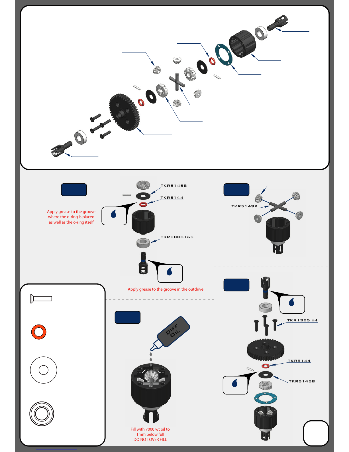
Apply grease to the groove
where the o-ring is placed
as well as the o-ring itself
Apply grease to the groove in the outdrive
Fill with 7000 wt oil to
1mm below full
DO NOT OVER FILL
TKR5145B
TKR5144
Bag A
Center Differential
(overview)
TKR5237K
TKR5149X
TKR5150
TKR5150
TKR5143
TKR5113
*TKR5237
*TKR5115
(Option)
TKR1325
M3x14mm Flat Head Screw
x4
TKR5144
TKR5145B
TKRBB08165
Ball Bearing(8x16x5mm)
x2
TKR5144
Differential 0-rings
x2
TKR5145B
Differential Shims (6x17mm)
x2
TKR1325 x4
TKR5149X
TKRBB08165
Diff
Oil
TKR5614X
TKR5614X
TKR5150
TKR5144
3
Grease
Grease
Grease
Grease
Step
A-2
Step
A-1
Step
A-4
Step
A-3
*TKR5149A
(Option)
*TKR5149A
(Option)
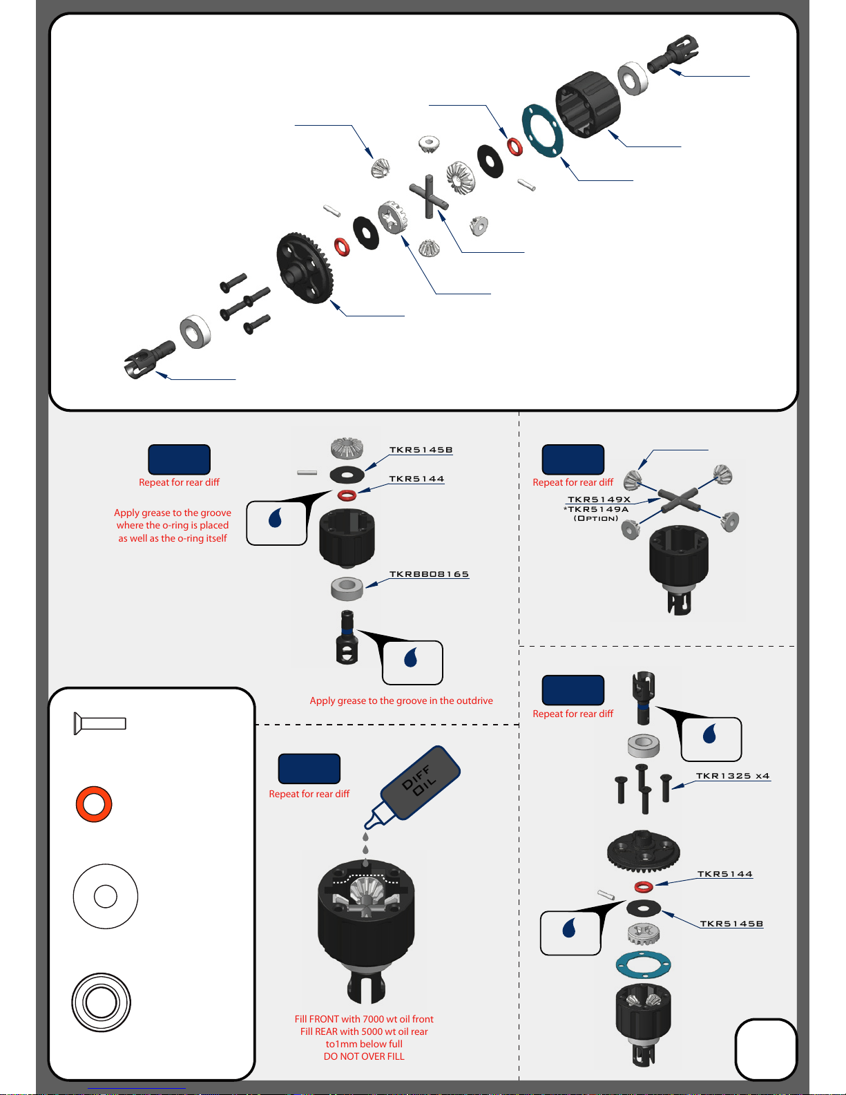
Apply grease to the groove
where the o-ring is placed
as well as the o-ring itself
Apply grease to the groove in the outdrive
Repeat for rear di
Fill FRONT with 7000 wt oil front
Fill REAR with 5000 wt oil rear
to1mm below full
DO NOT OVER FILL
Repeat for rear di
Repeat for rear di
Repeat for rear di
TKR5149X
*TKR5149A
(Option)
*TKR5149A
(Option)
TKR5145B
TKR5144
Bag B
Front and Rear Differential
(overview)
TKR5151
TKR5149X
TKR5150
TKR5150
TKR5143
TKR5113
TKR1325
M3x14mm Flat Head Screw
x8
TKR5144
TKR5145B
TKRBB08165
Ball Bearing(8x16x5mm)
x4
TKR5144
Differential 0-rings
x4
TKR5145B
Differential Shims (6x17mm)
x4
TKR1325 x4
TKRBB08165
Diff
Oil
TKR5614X
TKR5614X
TKR5150
TKR5144
4
Grease
Grease
Grease
Grease
Step
B-2
Step
B-1
Step
B-4
Step
B-3
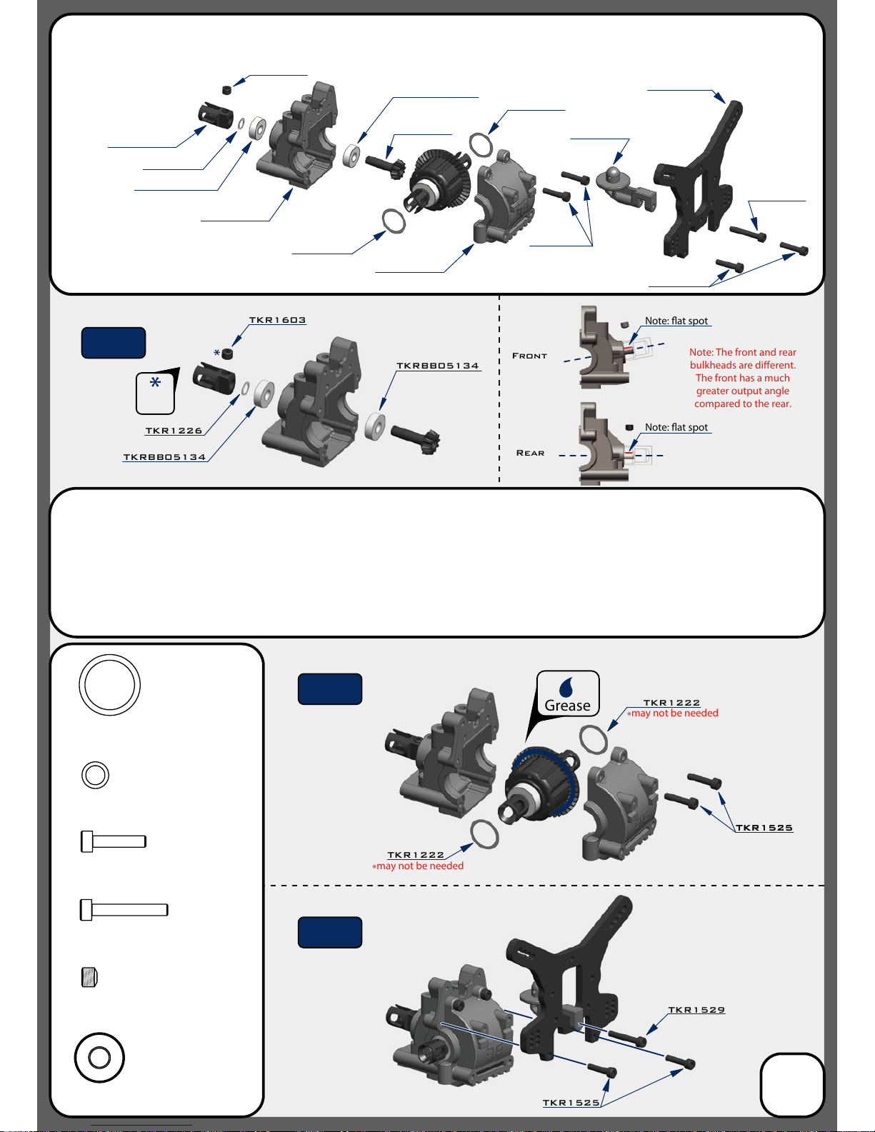
TKR1525
TKR5012
TKR5012
TKR5581
TKR5575X
TKR5152
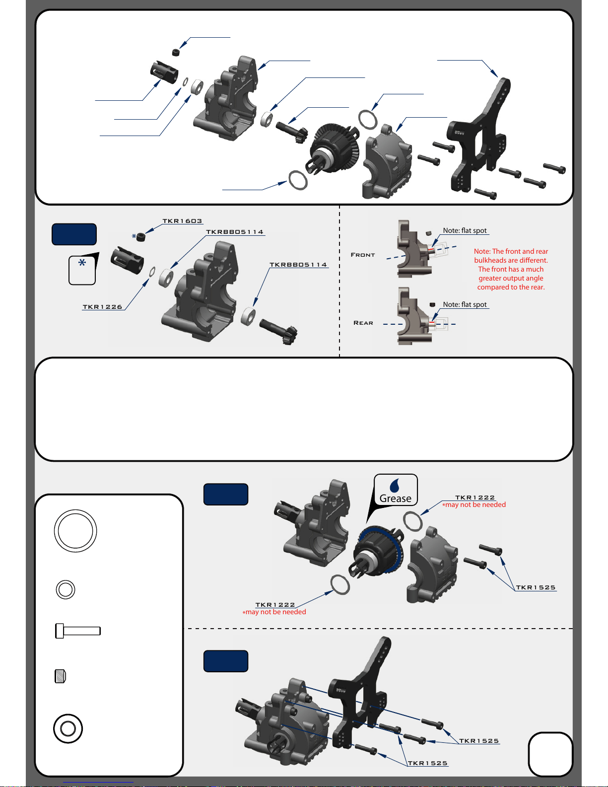
Front
Rear
Note: The front and rear
bulkheads are dierent.
The front has a much
greater output angle
compared to the rear.
x2
TKR1222
TKR1603
TKRBB05114
TKRBB05114
TKR1226
TKR1222
TKR1222
TKR1525
13x16x0.1mm Diff shim
TKR1222
TKR1222
TKR1226
TKRBB05114
TKRBB05114
TKR1525
TKR1525
M3x14mm Cap Head Screw
x6
TKR1603
M5x4mm Set Screw
TKRBB05114
Ball Bearing (5x11x4)
x2
x1
TKR1226
5x7x0.2mm shim
x1
TKR1603
Grease
Note: at spot
*
may not be needed
*
may not be needed
Note: at spot
*TKR5581C
(Option)
Bag C
Front Gearbox
(overview)
5
Thread
Lock
Step
C-1
Step
C-2
Step
C-3
Note: TKR1222 and TKR1226 Shims - The gear mesh should be tight without any binding. TKR1226 should
always be installed. Then test tment of the di with both TKR1222 shims on the gear-side of the di. If the di
turns freely without binding, continue to next step. If the di binds and does not turn freely (it will make a
grinding or crunching sound when spun), remove one TKR1222 shim from the gear side and install it onto the
other side of the di. Reassemble and test the mesh again. If it is still binding, remove the second TKR1222 shim
from the gear side and install it onto the other side of the di. When you are satised that you have the best
gear mesh possible continue to the next step. You may end up using only one shim on the gear side.
TKR5575X
TKR5016B
TKR5152
TKR5016B
TKR5584
TKR1222
TKR1222
TKR1525
TKR1529
TKR1222
TKR1529
TKR5181
TKR1525
TKR1222
TKR1525
TKR1226
TKRBB05134
TKR1525
M3x14mm Cap Head Screw
x4
TKR1603
M5x4mm Set Screw
x1
TKR1222
13x16x0.1mm Diff Shim
x2
TKR1226
5x7x0.2mm Shim
x1
TKR1603
TKRBB05134
TKRBB05134
TKR1226
TKRBB05134
TKR1603
TKR1525TKR1525
Grease
Front
Rear
Note: at spot
Note: at spot
*TKR5584C
(Option)
Note: The front and rear
bulkheads are dierent.
The front has a much
greater output angle
compared to the rear.
*
may not be needed
*
may not be needed
TKR1529
M3x20mm Cap Head Screw
x1
Bag D
Rear Gearbox
(overview)
6
Thread
Lock
Step
D-1
Step
D-2
Step
D-3
Note: TKR1222 and TKR1226 Shims - The gear mesh should be tight without any binding. TKR1226 should
always be installed. Then test tment of the di with both TKR1222 shims on the gear-side of the di. If the di
turns freely without binding, continue to next step. If the di binds and does not turn freely (it will make a
grinding or crunching sound when spun), remove one TKR1222 shim from the gear side and install it onto the
other side of the di. Reassemble and test the mesh again. If it is still binding, remove the second TKR1222 shim
from the gear side and install it onto the other side of the di. When you are satised that you have the best
gear mesh possible continue to the next step. You may end up using only one shim on the gear side.
TKRBB05134
Ball Bearing (5x13x4)
x2
TKR1529
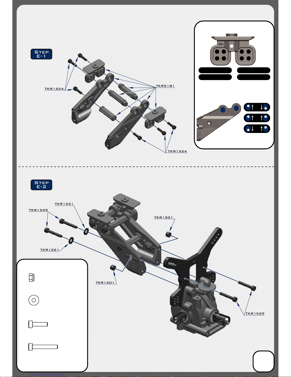
TKR1201
TKR1221
TKR1221
TKR1201
TKR1529
TKR1529
M3x20mm Cap Head Screw
x4
TKR1524
M3x12mm Cap Head Screw
x6
TKR1201
M3 Lock Nut Black
x2
TKR1221
M3x8mm Washer
x2
Step
E-1
Step
E-2
TKR1524
TKR1524
TKR5181
Bag E
Low Profile Wing Mount
7
SETTINGS
1 2
3 4
1 2
3 4
PO SITI ON SETT INGS
1 - RE AR WAR D LO W 2 - FO RE WA RD LO W
3 - RE AR WAR D HI GH 4 - FO RE WA RD HI GH
DO WNFO RCE SET TING S
(d ow nf or ce an gl es )
Note: Stock position setting is
# 3, Rearward High
Note: Stock downforce setting is 4
°
4
°
7
°
10
°
Stock Position
(”D” Block)
Stock Position
(”C” Block)
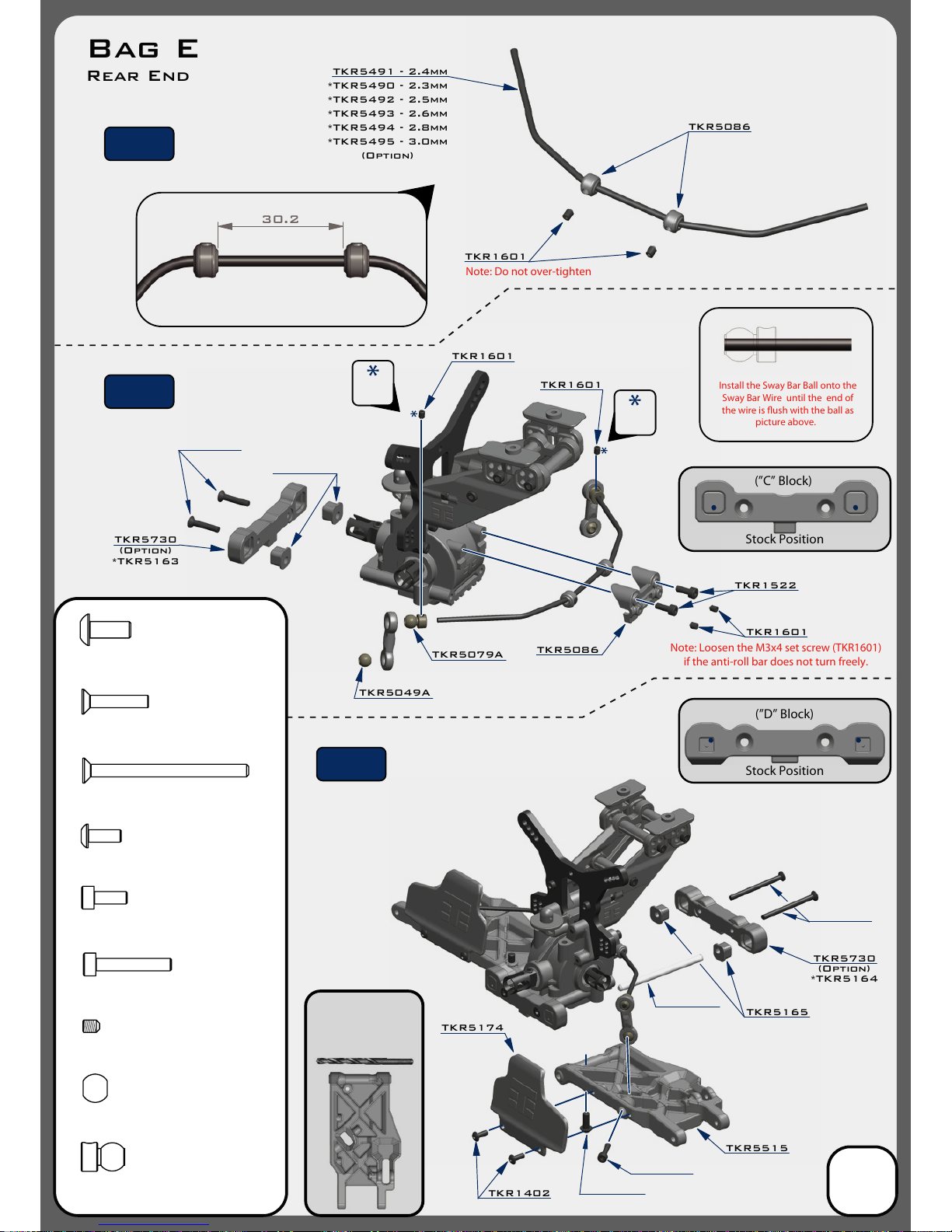
30.2
TKR1601
TKR1601
TKR1601
TKR5086
TKR5491 - 2.4mm
TKR5086
Install the Sway Bar Ball onto the
Sway Bar Wire until the end of
the wire is ush with the ball as
picture above.
Note: Loosen the M3x4 set screw (TKR1601)
if
the anti-roll bar does not
turn freely.
Note: Do not over-tighten
TKR5049A
TKR5730
TKR5730
TKR5165
TKR5515
TKR5174
TKR1402
TKR1601
TKR5079A
TKR1522
TKR1522
M3x8mm Cap Head Screw
x2
Bag E
Rear End
*TKR5490 - 2.3mm
*TKR5492 - 2.5mm
*TKR5493 - 2.6mm
*TKR5494 - 2.8mm
*TKR5495 - 3.0mm
(Option)
(Option)
*TKR5163
(Option)
*TKR5164
Thread
Lock
Thread
Lock
8
TKR1327
TKR1333
M3x40mm Flat Head Screw
x2
TKR1238
M4x10mm Droop Screw
x2
TKR5049A
Pivot Ball Sway Bar
x2
TKR5079A
Stabilizer Ball
x2
TKR1528
M3x18mm Cap Head Screw
x2
TKR1327
M3x16mm Flat Head Screw
x2
TKR1333TKR1333
TKR1238
TKR1528
TKR1601
M3x4mm Set Screw
x6
Step
F-1
Step
F-2
Step
F-3
TKR5020
TKR1402
M3x8mm Button Head Screw
x4
TKR5165
Note: With these stock settings,
Anti-Squat is: 1° / Rear Toe is: 2°
For reference: With center dot
inserts in both braces,
Anti-Squat = 3° / Rear Toe = 3°
Use a #19 drill bit or
4mm reamer to ream
arms until hinge pin
falls through freely.
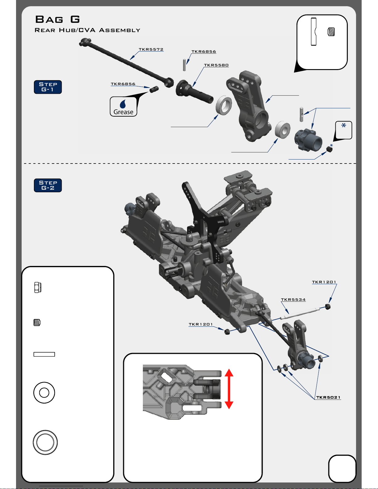
TKR5572
TKR6856
TKR5580
TKR6856
TKR5534
TKR5021TKR5021TKR5021
TKR1201
TKR1201
TKR6856
CV Joint Pin
x2
TKR1602
M4x4mm Set Screw
x2
TKR1201
M3 Locknut Black
x4
Grease
Step
G-1
Step
G-2
Changes to the wheelbase have a dramatic eect on handling,
since it shifts the disribution of weight over the rear wheels.
This adjusts traction. By shortening the wheelbase at the rear, you
are placing more weight over the rear wheels.
Changes to the wheelbase also change the amount of sweep the
rear driveshaft will have. More driveshaft sweep creates an eect
similar to anti-squat, where the rear end gets pushed upwards on
throttle. This helps reduce chassis slap landing jumps on throttle.
(FRONT)
(REAR)
TKRBB10154
Ball Bearing (10x15x4)
x2
TKRBB06135
Ball Bearing (6x13x5)
x2
Bag G
Rear Hub/CVA Assembly
9
Thread
Lock
Note: notch on pin
needs to line up
with set screw.
TKR5545
TKRBB10154
TKRBB06135
TKR5570-17
TKR1602

TKR5188
TKR5123
TKR5188
TKR5052A
This side mounts on hub
Note: angled link
This side mounts on shock tower
Note: straight link
TKR5053A
25.50
Note: Notch always goes
on
left side of vehicle
1
2
3
4
5
6
A
B
C
Stock position is 6/B
TKR1529
TKR1201
Right
TKR5053A
This side mounts on hub
Note: angled link
This side mounts on shock tower
Note: straight link
TKR5188
Left
TKR1529
TKR5123
TKR1201
M3 Locknut Black
x4
TKR1529
M3x20mm Cap Head Screw
x4
TKR5053A
Pivot Ball M3x6.8mm
No Flange
x2
TKR5052A
Pivot Ball M3x6.8mm
x2
TKR5188
TKR5052A
Step
G-3
Step
G-4
Bag G
Rear Camber Links
10

Use a #19 drill bit or
4mm reamer to ream
arms until hinge pin
falls through freely.
Stock Position
(”B” Block)
Stock Position
(”A” Block)
30.2
TKR1601
TKR1601
TKR1601
TKR5086
TKR5083 - 2.5mm
TKR5086
Install the Sway Bar Ball onto the
Sway Bar Wire until the end of
the wire is ush with the ball as
picture above.
Loosen the M3x4 set screw
(TKR1601) if
the anti-roll bar
does not
turn freely.
Note: Do not over-tighten
TKR1601
TKR1522
TKR1522
M3x8mm Cap Head Screw
x2
Bag H
Front End
*TKR5080 - 2.2mm
*TKR5081 - 2.3mm
*TKR5082 - 2.4mm
*TKR5084 - 2.6mm
*TKR5085 - 2.8mm
*TKR5087 - 3.0mm
(Option)
Thread
Lock
Thread
Lock
11
TKR1327
TKR1333
M3x40mm Flat Head Screw
x2
TKR1238
M4x10mm Droop Screw
x2
TKR5049A
Pivot Ball Sway Bar
x2
TKR5079A
Stabilizer Ball
x2
TKR1528
M3x18mm Cap Head Screw
x2
TKR1327
M3x16mm Flat Head Screw
x2
TKR1333
TKR1528
TKR1238
TKR5020
TKR1601
M3x4mm Set Screw
x6
Step
H-1
Step
H-2
Step
H-3
TKR5730
TKR5730
(Option)
*TKR5162
(Option)
*TKR5161
TKR5516
TKR5165
TKR5149A
TKR5165
TKR5165
Note: With these stock settings,
Kick Up is: 11° / Arm Sweep is: 0°
For reference: With center dot
inserts in both braces,
Kick Up = 10° / Arm Sweep = 0°

TKR5572
TKR5541B
TKR5554A
TKR1404
TKRBB06135
TKR5542
TKR5580
TKR1407
TKR1407
TKR5555A
TKRBB10154
TKR1404
TKR6856
CV Joint Pin
x4
TKR5554A
Spindle Pin Sleeve
x4
TKR5555A
Suspension Pin Sleeve
x4
Grease
TKR6856
TKR6856
TKRBB10154
Ball Bearing (10x15x4)
x2
TKRBB06135
Ball Bearing (6x13x5)
x2
TKR1404
M3x12mm Button Head Screw
x4
TKR1407
M3x16mm Button Head Screw
x4
Step
I-1
Step
I-2
Thread
Lock
TKR5570-17
TKR1602
TKR1602
M4x4mm Set Screw
x2
Bag I
Front Spindle / CVA Assembly
12
Note: notch on pin
needs to line up
with set screw.

TKR1529
Stock position is 3/B
TKR1221
TKR1201
TKR1201
TKR1529
26.00
TKR1201
M3 Lock Nut Black
x4
TKR1529
M3x20mm Cap Head Screw
x4
TKR5052A
Pivot Ball M3x6.8mm
x2
TKR5053A
Pivot Ball M3x6.8mm
No Flange
x2
TKR5188
TKR5123
TKR5188
TKR5052A
TKR5053A
Right
TKR5188
This side
mounts on hub
Note: no ange
This side
mounts on hub
Note: no ange
This side mounts
on shock tower
Note: ange
This side mounts
on shock tower
Note: ange
TKR5188
Left
TKR5123
TKR5053A
TKR5052A
TKR1221
M3x8mm Washer
x4
Note: Notch always goes
on
left side of vehicle
1
2
3
4
5
6
A
B
Step
I-4
Step
I-3
Bag I
Front Camber Links
13

TKR1323
TKRBB050825
TKRBB050825
Note: Apply
a small drop
of oil for
easy o-ring
installation.
Note: Tighten nut all the way down,
then back it o 3 full turns
Stock Position
(in REAR hole)
*Note orientation of Ackermann
plate when installing
TKR5117
TKR5056
TKR5123
TKR5052A
TKR5104
TKR5104
TKR5101X
TKR5231
TKR1201
TKRBB06103
TKRBB06103
TKR1529
Note: Stock bumpsteer setting is
4 washers
under the steering ball link.
4 x TKR1221
TKR1221
TKRBB06103
TKRBB050825
TKR5104
TKR5122
TKR1529
TKR5103
TKR5103
TKR1201
TKRBB06103
TKR5052A
28.50
TKR1323
M3x10mm Flat Head Screw
x2
TKR1201
M3 Lock Nut Black
x2
O-ring 16x12x2
TKR5231
x1
TKRBB06103
Ball Bearing (6x10x3)
x4
TKRBB050825
Ball Bearing (5x8x2.5)
x4
TKR1529
M3x20mm Cap Head Screw
x2
TKR5052A
Pivot Ball M3x6.8mm
x4
TKR1221
M3x8mm Washer
x8
*TKR5100
(Option)
TKR5052A
TKR5052A
TKR5052A
Thread
Lock
Thread
Lock
Thread
Lock
Right
Left
Step
J-1
Step
J-2
Step
J-3
Step
J-4
Bag J
Steering Assembly
(overview)
14
Note: Notch always goes
on
left side of vehicle

TKR5107
TKR1323
TKR1201
TKR1443
TKR5102A
TKR1443
Note: on steps K-2, K-3 and K-4 Do not
tighten the
screws all the way down until
the assembly steps are complete. Position
the entire front assembly on the chassis
and tighten each screw evenly.
TKR1522
TKR5166
TKR1443
TKR1344
TKR1344
TKR1343
TKR5062
Note: Inititial bumpsteer setting
is two
washers above and below the steering ball link.
TKR5181
TKR1522
M3x8mm Cap Head Screw
x1
TKR1343
M4x10mm Flat Head Screw
x2
TKR1344
M4x12mm Flat Head Screw
x6
TKR1201
M3 Lock Nut Black
x2
TKR1323
M3x10mm Flat Head Screw
x1
TKR1443
M4x10mm Button Head Screw
x5
TKR1529
M3x20mm Cap Head Screw
x2
TKR1221
M3x8mm Washer
x8
Note Step K-2:
Line up the bottom of the
steering posts (TKR5102A)
with the corresponding recess
cut in the
chassis.
Thread
Lock
Thread
Lock
Step
K-3
Step
K-4
Step
K-1
Step
K-2
Bag K
Front End Assembly
17

TKR5107
TKR5260
TKR5263
TKR1522
TKR5579
TKR1443
TKR5062
TKR1344
TKR1343 x5
TKR1443
TKR5062
TKR5576
TKR1344 x5
TKR1524
TKR5263
*TKR5262
(option)
TKR1522
M3x8mm Cap Head Screw
x2
TKR1524
M3x12mm Cap Head Screw
x4
TKR1343
M4x10mm Flat Head Screw
x5
TKR1443
M4x10mm Button Head Screw
x2
TKR1344
M4x12mm Flat Head Screw
x7
Thread
Lock
Thread
Lock
Step
L-1
Step
L-3
Step
L-2
Step
L-4
Bag L
Center/Rear
Assembly
16

17
Shock Filling Instructions
For both front and rear shocks
The following steps and information will provide you with the best way to ll and bleed your
shocks. After thorough testing, we've found it's easiest to complete steps 1 through 3 on each
shock before moving onto step 4. By the time you've nished step 3 on the last shock the rst
one will be ready for step 4.
Standard or Vented Cap Build:
Step 1: Extend the shock shaft all the way down. Fill the shock with oil until the it is about 90% full.
Step 2: Slowly pump the shock shaft up and down 3-5 times to release air bubbles from underneath
the piston.
Step 3: Let the shock rest vertically with the shock shaft fully extended for ve minutes or until all
the air bubbles have released.
Step 4: Next you will top o the shock with oil, to about 1-2mm below the top edge.
(If you do overll the shock, it won’t hurt performance, it will just spill out and make a little bit of a
mess. If you underll the shock, it will cause air to be trapped inside.)
Step 5: Place the bladder INSIDE the shock cap and put a few drops of oil on the bladder.
Step 6: Put a paper towel down below the build to catch drips and have another ready to
wipe o excess oil. Place the cap on the shock and screw down about half way. Lay the shock
over about 45 degrees with the bleeder hole facing up.
Step 6A: (Standard non-vented) Push the shaft in for the amount of rebound desired.
Step 6B: (Vented “Stock”) Push the shaft in until about 15mm of shaft is showing.
• Make sure that you match the rebound amount between the left and right shocks.
• Oil should be oozing out of the bleeder hole.
Step 7: Hold the cap rmly in place with the bleeder hole facing up and turn the shock body until
hand tight. The shock will continue to ooze oil.
Step 8: Fully tighten down each shock with shock tools until cap is secure and wipe excess oil away.
Emulsion Build:
Prep your shock caps TKR6018 (optional for EB48) accordingly by drilling out the large angled
bleeder hole in the top of the cap. Place the larger thin o-ring around the base of the threads
where the shock cap screws on (see diagram on the next page). This seal is crucial to the build.
Follow steps 1-4 above.
Step 5: Rebound is more of a natural side eect of an emulsion shock. It’s not something that can
be set accurately because you run the risk of hydrolocking the shock if you do not push the shaft
all the way in when you bleed it. For now leave the shaft fully extended.
Step 6: Fill the shock up, over lling just slightly without spilling to create a small dome of oil.
Step 7: Place a little bit of oil in the shock cap and quickly put the shock cap on the shock body.
Tighten the cap all the way down. Very slowly push the shaft in. Oil will start to bleed out of the top
of the cap. While wiping away excess oil, continue to slowly push the shaft in ALL THE WAY.
If no oil comes out when the shaft is fully inserted, you will need to start over at step 6.
Step 8: Install the TKR1341 M4x6mm at head screw and TKR5125 black o-ring to seal
the cap (see diagram). Tighten until o-ring is fully seated.

TKR6035
TKR6140
TKR1528
TKR1202
Note: slot in spring
perch should face
outside of vehicle.
TKR1605
TKR6008
TKR6008
TKR6009
TKR6002
M2.5 Lock Nut Zinc
TKR1200
x2
TKR1528
M3x18mm Cap Head Screw
x2
TKR1211
M3 Lock Nut Flange Black
x2
*TKR6046
*TKR6047
*TKR6048
*TKR6036
*TKR6037
*TKR6038
*TKR6039
(Option)
TKR1200
TKR6008
TKR6004
TKR5049A
TKR1341
*TKR6004T
(Option)
*TKR6050
*TKR6051
*TKR6052
*TKR6053
*TKR6054
*TKR6063
*TKR6064
*TKR6065
(Option)
Note:
shaft guide
orientation
Note:
front shocks use
shorter shock bodies -
TKR6002,
shorter shock shafts -
TKR6004,
shorter springs -
TKR6035
and shorter shock boots -
TKR6143
Note: Use green
slime or oil on
shock shaft
threads AND
O-rings to
prevent tearing
and leaking.
TKR6018
TKR6009
Drill 1-2mm
hole here
for emulsion
Drill 1-2mm
hole here
for bleeder
*TKR6013
(Option)
TKR6018
*TKR6003
(Option)
*TKR6015
(Option)
TKR5125
Step
M-1
Step
M-2
Step
M-3
Vented build requires a
1-2mm hole drilled in
addition to the bleeder hole
*Do not drill
bleeder
hole for this
build
**Bladder not
used in this
build
*NOTE: Vented is the prefered stock build
TKR6140
TKR6143
Note: Shock boots
must be installed
before attaching
rod end.
TKR1202
M4 Lock Nut Black
x2
TKR1211
TKR6007
TKR5527
Note: Tighten TKR1211 lock nut all the way down, then back o 1/4 turn. Use thread lock!
Thread
Lock
Bag M
Front Shock Assembly
18
Stock shock position is outside
hole on the arm and
inside hole on the tower
Stock front ride height is 27mm
Shock length (droop) is 105mm
TKR1341
M4x6mm Flat Head Screw
X2
Vented
Build
Standard
Build
Emulsion
Build
#350wt
shock oil
Shock Building Options
TKR1605
M3x10mm Set Screw
x2

TKR6030
TKR6140
TKR1528
TKR6007
TKR5527
Note: slot in spring
perch should face
outside of vehicle.
TKR1202
TKR1605
TKR6008
TKR6008
TKR6009
TKR6016
M2.5 Lock Nut Zinc
TKR1200
x2
TKR1528
M3x18mm Cap Head Screw
x2
TKR1211
M3 Lock Nut Flange Black
x2
*TKR6041
*TKR6042
*TKR6043
*TKR6031
*TKR6032
*TKR6033
*TKR6034
*TKR6055
*TKR6056
(Option)
TKR1200
TKR6008
TKR6017
TKR5049A
TKR1341
*TKR6017T
(Option)
*TKR6050
*TKR6051
*TKR6052
*TKR6053
*TKR6054
*TKR6063
*TKR6064
*TKR6065
(Option)
Note:
shaft guide
orientation
Note:
rear shocks use
longer shock bodies -
TKR6016,
longer shock shafts -
TKR6017,
longer springs -
TKR6030
and longer shock boots -
TKR6144
Note: Use green
slime or oil on
shock shaft
threads AND
O-rings to
prevent tearing
and leaking.
TKR6018
TKR6009
Drill 1-2mm
hole here
for emulsion
Drill 1-2mm
hole here
for bleeder
*TKR6013
(Option)
TKR6018
*TKR6003
(Option)
*TKR6015
(Option)
TKR5125
Step
N-1
Step
N-2
Step
N-3
Vented build requires a
1-2mm hole drilled in
addition to the bleeder hole
*Do not drill
bleeder
hole for this
build
**Bladder not
used in this
build
*NOTE: Vented is the prefered stock build
TKR6140
TKR6143
Note: Shock boots
must be installed
before attaching
rod end.
TKR1202
M4 Lock Nut Black
x2
TKR1211
Note: Tighten
TKR1211 lock
nut all the way
down, then back
o 1/4 turn.
Use thread lock!
Thread
Lock
Bag N
Rear Shock Assembly
19
Stock shock position is outside
hole on the arm and
ouside hole on the tower
Stock rear ride height is 28mm
Shock length (droop) is 117mm
TKR1341
M4x6mm Flat Head Screw
X2
Vented
Build
Standard
Build
Emulsion
Build
#200wt
shock oil
Shock Building Options
TKR1605
M3x10mm Set Screw
x2

TKR5060
TKR5065
Steering servo (not included)
TKR1525
ESC (not included)
double sided tape
TKR5065
TKR5125
Note: Install ESC tray on the
mudguard (do not overtighten)
.
Note: CA glue 3 black o-rings (TKR5125) to the bottom legs of the ESC tray.
TKR1401
TKR1322
TKR1525TKR1525
TKR5065
TKR5065
TKR5065
TKR1401
TKR1322
TKR1322
TKR1401
RX (not included)
Transponder (not included)
TKR1401
M3x6mm Button Head Screw
x6
TKR1322
M3x8mm Flat Head Screw
x5
TKR1525
M3x14mm Cap Head Screw
x6
TKR5125
O-ring 3x7mm
x3
TKR1221
M3X8mm Washer
x4
TKR1221
TKR1221
Note: Feed the servo wire underneath the esc tray
in between the mounting screws on the mud guard,
then feed both ESC and servo wires into the RX
box as shown. I
nstall wire retainers (TKR5065)
to secure them properly.
CA
glue
Step
O-4
Step
O-3
Step
O-1
Step
O-2
Bag O
Final Assembly
20
*TKR5060C
(Option)

Hook side
Battery Strap Installation:
1. Fit straps loosely
2.
Position on chassis
3.
Proceed to step P-2
TKR1343TKR1343
TKR1341
TKR1343
TKR1322
TKR1523
TKR5212
Motor (not included)
TKR1346
TKR1228
TKR1346
TKR1228
TKR1322
M3x8mm Flat Head Screw
X6
TKR1341
M4x6mm Flat Head Screw
X6
TKR1343
M4x10mm Flat Head Screw
X5
TKR1228
M4 Countersunk Washer
X2
Logo side
Thread
Lock
Thread
Lock
Thread
Lock
TKR1523
M3x10mm Cap Head Screw
x2
Thread
Lock
TKR1346
M4x15mm Flat Head Screw
X2
Bag P
Final Assembly
21
Note: Install MOD1
pinion (TKR4171-4190)
at this step.
Adjust gear mesh
and tighten screws
(TKR1445) well.
*Use thread lock.
Note: Option required
for 1/8th scale motor use
*TKR5211X
(Option)
Step
P-2
Step
P-3
Step
P-4
Step
P-5
Step
P-1

Bag P
Final Assembly
TKR5058A
Pivot Ball M3x5.8mm
No Flange
x2
TKR1201
M3 Lock Nut Black
x2
TKR5230
M3x18 Threaded Rod
x1
TKR5058A
TKR1325
TKR1201
TKR1221
TKR1201
TKR1407
TKR5230
TKR5056
TKR5058A
TKR5056
Note: Oset servo arm so it is parallel with the connecting arm at neutral or zero servo position.
PARALLEL
1mm
22
TKR1407
M3x16mm Button Head Screw
x1
TKR1221
M3x8mm Washer
x2
TKR1325
M3x14mm Flat Head Screw
x1
Step
P-6
Step
P-7
Step
P-8
TKR5220
TKR1221
*TKR5251
*TKR5252
*TKR5253
(Option)

Bag Q
Wing/Wheels/Body
23
TKR5116
TKR1235
TKR1235
TKR5037
*TKR5037B
*TKR5037Y
(Option)
*TKR5116B
*TKR5116C
(Option)
TKR1201
TKR1325
TKR1220
TKR5181
TKR5181
TKR1220
TKR1325
M3x14mm Flat Head Screw
x2
TKR1201
M3 Lock Nut Black
x2
TKR5116
Wheel Nut
x4
TKR1235
Body Clip
x2
Note: It may be necessary to cut holes in the body for ventilation.
Step
Q-1
Step
Q-2
Step
Q-3
TKR1220
M4 Countersunk Washer
X2

24
Parts List
TKR40008K – Battery Straps (EB48, black, 2 cell, 3pcs)
TKR5010 – Battery Tray, Mud Guard (EB48, left side)
TKR5011 – Radio Tray, Mud Guard (EB48, right side)
TKR5012 – Gearbox (front)
TKR5016B – Gearbox (rear, angled)
TKR5020 – Hinge Pins (inner, front/rear)
TKR5037 – Wing (white)
TKR5049A – Pivot Balls (6.8mm, no ng, sway bar, shck ends, almnm, 4pcs)
TKR5052A – Pivot Balls (6.8mm, inside camber, steering links, aluminum, 4pcs)
TKR5053A – Pivot Balls (6.8mm, anged, outside camber, aluminum, 4pcs)
TKR5056 – Rod Ends (5.8mm, brake/steering/sway bar linkage, 8pcs)
TKR5058A – Pivot Balls (5.8mm, no ange, brake/steering link, aluminum, 4pcs)
TKR5060 – Steering Servo Brace (aluminum, gun metal ano)
TKR5062 – Chassis Brace Set (front/rear/center)
TKR5065 – ESC Tray and Radio/Battery Tray Accessories
TKR5079A – Stabilizer Balls (6.8mm, sway bars, aluminum, 4pcs)
TKR5083 – Sway Bar (2.5mm, front)
TKR5086 – Sway Bar Mounts
TKR101X - Servo Saver Spring (HD, EB48, SCT410, NB48)
TKR5102A – Steering Posts (aluminum)
TKR5103 – Servo Saver Post (aluminum, gun metal ano)
TKR5104 – Steering Bell Cranks
TKR5107 – Steering Top Plate, Center Di Top Plate, Center Di Rear Support
TKR5116 – Wheel Nuts (17mm, serrated, gun metal ano, M12x1.0, 4pcs)
TKR5117 - Ackerman Plate (composite)
TKR5122 – Steering Rack Bushings (aluminum, gun metal ano, 2pcs)
TKR5123 – Turnbuckle (steering links, 2pcs)
TKR5125 – O-Ring (ESC tray, 3pcs)
TKR5126 – Antenna tube (universal, w/ caps, 5pcs)
TKR5166 - Front Bumper (revised, EB/NB/ET/NT48)
TKR5165 - V2 Hinge Pin Inserts, Wheelbase Shims (EB/NB/ET/NT/SCT)
TKR5174 - Rear Arm Mud Guards (for TKR5184, EB/NB)
TKR5181 - Low Prole Wing Mount and Body Mounts (EB/NB48/EB48SL)
TKR5188 - Rod Ends (6.8mm, M4 thread, SCT/SL, 8pcs)
TKR5211X – Motor Mount Insert (aluminum, gun metal ano)
TKR5220 – Servo Horns (steering, brakes)
TKR5230 – Steering linkage (M3x18mm threaded rod, 10pcs)
TKR5231 – Servo Saver Nut and Spring
TKR5245 – Body (.040 lexan, EB48)
TKR5249 – Decal Sheet (EB48SL)
TKR5260 - CNC Split Cntr Di Mount (mtr mnt only, 7075, gun metal ano, EB/ET/SCT)
TKR5263 - Split Cntr Di Mount (composite, requires TKR5260, EB/ET/SCT/SL)
TKR5288 – Chassis (7075, black anodized, lightened)
TKR5491 - Sway Bar (2.4mm, rear)
TKR5515 - Suspension Arms (rear, SCT.3/SL)
TKR5516 - Suspension Arms (front, SCT.3/SL)
TKR5527 – Shock Standos (SCT410, 2pcs)
TKR5534 – Hinge Pins (SCT410, outer, rear)
TKR5541B - Spindles (6x13x5mm outer bearing, L/R, SCT410/EB48SL)
TKR5542 – Spindle Carriers (SCT410, left, right)
TKR5545 - Rear Hubs (L/R, CV or uni, SCT.3/SL)
TKR5554A – Spindle Bushings (SCT410, 4pcs, aluminum, hard ano)
TKR5555A – Arm Bushings (SCT410, 4pcs, aluminum, hard ano)
TKR5570-17 - 17mm Hub Adapter Set (SCT410, buggy width, aluminum, 2pcs)
TKR5572 – Driveshafts (SCT410, f/r, hardened steel, 2pcs)
TKR5575X – Di Coupler (SCT410, f/r, hardened steel, lightened)
TKR5576 – Driveshaft (SCT410, center, rear, hardened steel)
TKR5579 - Tapered Driveshaft (SCT/EB48SL, center, front, 7075 aluminum, black ano)
TKR5580 – Stub Axles for Adapters (For: TKR5570-17, SCT410, hardened steel, 2pcs)
TKR5581 - Shock Tower (front, 7075, black ano, SCT.3/SL)
TKR5584 - Shock Tower (rear, 7075, black ano, SCT.3/SL)
TKR5730 - V2 Adj. Hinge Pin Brace Set (composite, EB/NB/ET/NT/SCT)
TKR6856 – CV Rebuild kit (f/r, for 2 axles)
Dierential List
TKR5113 – Dierential Case (f/c/r)
TKR5143 – Dierential Seals (3pcs)
TKR5144 – Dierential O-Rings (6pcs)
TKR5145B – Dierential Shims (revised, 6x17mm, 6pcs)
TKR5149X – Dierential Cross Pins (composite, 3pcs)
TKR5150 – Dierential Gear Set (internal gears only)
TKR5151 – Dierential Ring Gear (40t, straight cut)
TKR5152 – Di Pinion (10T, straight cut)
TKR5237K – Spur Gear (44t, black, composite)
TKR5614X – Dierential Outdrives (SCT410, f/c/r, lightened)
TKR5647 – Complete Center Dierential (SCT410)
TKR5648 – Complete F/R Dierential (SCT410)
Shocks List
TKR6002 – Shock Body (front, aluminum, hard ano, 2pcs)
TKR6004 – Shock Shafts (front, steel, 2pcs)
TKR6007 - Shock Cap Bushings (4pcs, EB/NB/ET/NT/SCT)
TKR6008 – Shock Shaft Guide, Piston, and Bushing Set (for 2 shocks)
TKR6009 – Shock O-Ring and Bladder Set (for 2 shocks)
TKR6016 – Shock Body (rear, aluminum, hard ano, 2pcs)
TKR6017 – Shock Shafts (rear, steel, 2pcs)
TKR6018 – Shock Cap and Spring Adjuster Set (composite, for 2 shocks)
TKR6030 – Shock Spring Set (rear, 1.4 x 11.0T, 85mm, pink)
TKR6035 – Shock Spring Set (front, 1.5 x 9.0T, 70mm, pink)
TKR6140 - Locking Shock Rod End and Spring Perch Set (EB/NB/ET/NT/SCT)
TKR6143 - Shock Boots (medium length, front, EB/NB/SCT, 2pcs)
TKR6144 - Shock Boots (long length, rear EB/NB/SCT, front ET/NT, 2pcs)
Bearings List
TKRBB050825 – Ball Bearing (5x8x2.5mm, 4pcs)
TKRBB05114 – Ball Bearing (5x11x4, 4pcs)
TKRBB05134 – Ball Bearing (5x13x4, 4pcs)
TKRBB06103 – Ball Bearing (6x10x3, 4pcs)
TKRBB06135 – Ball Bearing (6x13x5, 4pcs)
TKRBB08165 – Ball Bearing (8x16x5, 4pcs)
TKRBB10154 – Ball Bearing (10x15x4, 4pcs)
TKR5004 - EB48SL 1/8th Comptetion Super Light Buggy Complete Kit
Hardware List
TKR1200 – M2.5 Locknuts (zinc nish, 10pcs)
TKR1201 – M3 Locknuts (black, 10pcs)
TKR1202 - M4 Locknuts (black, 10pcs)
TKR1211 – M3 Locknuts (anged, black, 10pcs)
TKR1220 – M3 Countersunk Washers (aluminum, natural, 10pcs)
TKR1221 – M3x8mm Washer (black, 10pcs)
TKR1222 – 13x16x.1mm Di Shims (10pcs)
TKR1226 - 5x7x.2mm shims (10pcs)
TKR1228 - M4 Countersunk Washer (black, 10pcs)
TKR1235 – Body Clips (10pcs)
TKR1238 - Droop Adjustment Screws (M4x10mm, 8pcs)
TKR1322 – M3x8mm Flat Head Screws (black, 10pcs)
TKR1323 – M3x10mm Flat Head Screws (black, 10pcs)
TKR1325 - M3x14mm Flat Head Screws (black, 10pcs)
TKR1327 - M3x16mm Flat Head Screws (black, 10pcs)
TKR1333 - M3x40mm Flat Head Screws (black, 10pcs)
TKR1341 - M4x6mm Flat Head Screws (black, 10pcs)
TKR1343 - M4x10mm Flat Head Screws (black, 10pcs)
TKR1344 - M4x12mm Flat Head Screws (black, 10pcs)
TKR1346 - M4x15mm Flat Head Screws (black, 10pcs)
TKR1402 - M3x8mm Button Head Screws (black, 10pcs)
TKR1404 - M3x12mm Button Head Screws (black, 10pcs)
TKR1407 - M3x16mm Button Head Screws (black, 10pcs)
TKR1443 - M4x10mm Button Head Screws (black, 10pcs)
TKR1522 - M3x8mm Cap Head Screws (black, 10pcs)
TKR1523 – M3x10mm Cap Head Screws (black, 10pcs)
TKR1524 - M3x12mm Cap Head Screws (black, 10pcs)
TKR1525 - M3x14mm Cap Head Screws (black, 10pcs)
TKR1528 - M3x18mm Cap Head Screws (black, 10pcs)
TKR1529 - M3x20mm Cap Head Screws (black, 10pcs)
TKR1601 - M3x4mm Set Screws (black, 10pcs)
TKR1602 – M4x4mm Set Screws (black, 10pcs)
TKR1603 - M5x4mm Set Screws (black, 10pcs)
TKR1605 - M3x10mm Set Screws (black, 10pcs)
Option Parts
TKR1103 - Turnbuckle Wrench (4mm, 5mm, hardened steel)
TKR1119 - 5.5mm / 7.0mm Wrench (hardened steel)
TKR1240 - Lower Shock Mount Screws (2 CW thread, 2 CCW thread, EB/NB/SCT)
TKR5037B – Wing (black)
TKR5037Y – Wing (yellow)
TKR5060C – Steering Servo Brace (carbon ber)
TKR5080 – Sway Bar (f/r, 2.2mm)
TKR5081 – Sway Bar (f/r, 2.3mm)
TKR5082 – Sway Bar (f/r, 2.4mm)
TKR5084 – Sway Bar (f/r, 2.6mm)
TKR5085 – Sway Bar (f/r, 2.8mm)
TKR5087 – Sway Bar (f/r, 3.0mm)
TKR5100 – Ackerman Plate (aluminum, gun metal ano)
TKR5149A - Di Cross Pins (aluminum, 6pcs, requires TKR5150)
TKR5161 - V2 Adj. Hinge Pin Brace (”A” block, 7075, EB/NB/ET/NT/SCT)
TKR5162 - V2 Adj. Hinge Pin Brace (”B” block, 7075, EB/NB/ET/NT/SCT)
TKR5163 - V2 Adj. Hinge Pin Brace (”C” block, 7075, EB/NB/ET/NT/SCT)
TKR5164 - V2 Adj. Hinge Pin Brace (”D” block, 7075, EB/NB/ET/NT/SCT)
TKR5174 – Rear Arm Mud Guards (for TKR5184, EB/NB)
TKR5237 – Spur Gear (44t, composite, natural color)
TKR5251 – Aluminum Servo Horn (23t spline, Airtronics/JR/KO Servos)
TKR5252 – Aluminum Servo Horn (24t spline, Hitec Servos)
TKR5253 – Aluminum Servo Horn (25t spline, Futaba/Pro-Tek/Savox Servos)
TKR5261 - CNC Split Cntr Di Mnt (complete, 7075, gun metal ano, EB/ET/SCT)
TKR5262 - CNC Split Cntr Di Mount (di mounts only, 7075, gun metal ano, EB/ET/SCT)
TKR5490 – Sway Bar (rear, 2.3mm)
TKR5492 – Sway Bar (rear, 2.5mm)
TKR5493 – Sway Bar (rear, 2.6mm)
TKR5494 – Sway Bar (rear, 2.8mm)
TKR5495 – Sway Bar (rear, 3.0mm)
TKR5581C - Shock Tower (front, carbon ber, SCT.3/SL)
TKR5584C - Shock Tower (rear, carbon ber, SCT.3/SL)
TKR6003 – Vented Shock Caps (aluminum, black ano, 2pcs)
TKR6003B – Non-Vented Shock Caps (aluminum, black ano, 2pcs)
TKR6004T – Shock Shafts w/ TiNi coating (front, steel, 2pcs)
TKR6009B – Shock O-Ring Set (16pcs)
TKR6013 – Shock Adjustment Nuts (aluminum, gun metal ano, 2pcs)
TKR6015 – Shock Cartridge Caps (aluminum, gun metal ano, 2pcs)
TKR6017T – Shock Shafts w/ TiNi coating (rear, steel, 2pcs)
TKR6031 – Shock Spring Set (rear, 1.4 x 10.5T, 85mm, green)
TKR6032 – Shock Spring Set (rear, 1.4 x 10.0T, 85mm, yellow)
TKR6033 – Shock Spring Set (rear, 1.4 x 9.5T, 85mm, orange)
TKR6034 – Shock Spring Set (rear, 1.4 x 9.0T, 85mm, red)
TKR6036 – Shock Spring Set (front, 1.5 x 8.5T, 70mm, green)
TKR6037 – Shock Spring Set (front, 1.5 x 8.0T, 70mm, yellow)
TKR6038 – Shock Spring Set (front, 1.5 x 7.5T, 70mm, orange)
TKR6039 – Shock Spring Set (front, 1.5 x 7.0T, 70mm, red)
TKR6041 – Shock Spring Set (rear, 1.4 x 12.5T, 80mm, white)
TKR6042 – Shock Spring Set (rear, 1.4 x 12.0T, 80mm, grey)
TKR6043 – Shock Spring Set (rear, 1.4 x 11.5T, 80mm, black)
TKR6046 – Shock Spring Set (front, 1.5 x 10.5T, 65mm, white)
TKR6047 – Shock Spring Set (front, 1.5 x 10.0T, 65mm, grey)
TKR6048 – Shock Spring Set (front, 1.5 x 9.5T, 65mm, black)
TKR6050 - Shock Pistons (CNC, conical, 10x1.1mm)
TKR6051 - Shock Pistons (CNC, conical, 8x1.3mm)
TKR6052 - Shock Pistons (CNC, conical, 10x1.2mm)
TKR6053 - Shock Pistons (CNC, conical, 8x1.4mm)
TKR6054 - Shock Pistons (CNC, conical, 10x1.3mm)
TKR6055 – Shock Spring Set (rear, 1.4 x 8.5T, 80mm, blue)
TKR6056 – Shock Spring Set (rear, 1.4 x 8.0T, 80mm, purple)
TKR6063 – Shock Pistons (CNC, conical, 6×1.5, 10.6mm²)
TKR6064 – Shock Pistons (CNC, conical, 6×1.6, 12.1mm²)
TKR6065 – Shock Piston Blanks (CNC, conical, 16 dimples, 16mm)
TKR6146 – Shock Cartridge Set (CNC, Delrin, EB/NB/ET/NT/SCT)

Stock Set Up
0
27
-2
0
11
2
2
2.5
105 117
3
2
2.4
7 7 5
.5 total
-2
28
0 0
2
3
350
CST
10 x 1.2
Pink
vent vent
Pink
10 x 1.2
CST
200
4
2


Tekno RC
10755 Scripps Poway Pkwy #598
San Diego CA 92131
USA
 Loading...