

Page 1

V
Note: The latest releases of the Technical Reference Manuals are available at:
Ref. : M830_TECH (Board Rev. 2)
IPer-830
Celeron-Based Industrial SBC
Technical Reference Manual
Version 1.4, February 2003
ftp://ftp.kontron.ca/support/Product_manuals/
www.kontron.com
Page 2

FOREWORD
The information in this document is provided for reference purposes only. Kontron does
not assume any liability for the application of information or the use of prod ucts de scrib e d
herein.
This document may contain information or refer to products protected by the copyrights or
patents of others and does not convey any license under the patent r i ghts of Kontron, nor
the rights of others.
Printed in Canada.
Copyright 2003 by Kontron Inc., Boisbriand, Qc J7G 2A7.
Page 3

DOCUMENTATION SURVEY
VIPer 830 – Celeron-Based Industrial SBC
Technical Reference Manual, Rev. 1.4
Your comments are valuable for us and will contribute to improve the quality of this product by
complementing and returning this form.
1. Overall r ating of the Technical Reference Manual:
2. Was the information you were seeking easy to find?
If no, can you comment? _________________ ____________________________________________________
3. What section of this manual do you refer to t he most? ______________________________________________
4. How can you rate this manual?
In terms of clarity of information:
Comments: _______________________________________________________________________________
_________________________________________________________________________________________
In terms of complexity:
Comments: _______________________________________________________________________________
_________________________________________________________________________________________
In terms of classifi cation of information:
Comments: _______________________________________________________________________________
_________________________________________________________________________________________
5. Is ther e missing information?
If yes, what informa tion is missing?_______________________ _____________________________________
_________________________________________________________________________________________
6. Is some information not properly or clearly explained?
If yes, can you comment?___________________________________ _________________________________
________________________________________________________________________________
7. Additional c o m ments (any changes or mod ifications to this man ual, etc.): ______________________________
_________________________________________________________________________________________
_________________________________________________________________________________________
Please send your comments to:
Kontron Inc
Technical Writing dept.
616 Curé Boivin, Boisbriand
(Québec) CANADA J7G 2A7
❑ Excellent ❑ Satisfactory ❑ Fair ❑ Poor
❑ Yes ❑ No
❑ Excellent ❑ Satisfactory ❑ Fair ❑ Poor
❑ Too technical ❑ Just OK ❑ Not technical enough
❑ Excellent ❑ Satisfactory ❑ Fair ❑ Poor
❑ Yes ❑ No
❑ Yes ❑ No
Optional
Name _________________________________
Company ______________________________
Address _______________________________
______________________________________
Page 4

ADDITIONAL COMMENTS
Page 5

READ ME FIRST
WARNING
Danger of explosion when replacing with wrong type of battery. Replace
only with the same or equivalent type recommended by the manufacturer.
Dispose of used batteries according to the manufacturer's instructions.
ATTENTION
Il y a danger d'explosion s'il y a remplacement incorrect de la batterie.
Remplacer uniquement avec une batterie du même type ou d'un type
équivalent recommandé par le fabriquant. Mettre au rebut les batteries
usagées conformément aux instructions du fabriquant.
ACHTUNG
Explosions gefahr bei falschem batteriewechsel. Verwenden sie nur die
empfohlenen batterietypen des herst ellers. Entsorgen sie die verbrauchten
batterien laut gebrauchs anweisung des he rstellers.
ATENCION
Puede explotar si la pila no este bien reemplazada. Solo reemplazca la pila
con tipas equivalentes segun las instrucciones del manifacturo. Vote las
pilas usadas segu n la s instrucciones de l manifacturo
Page 6

TABLE OF CONTENTS
PART 1 - PRODUCT DESCRIPTION
1.
PRODUCT OVERVIEW ................................................................................1-1
1.1. DESCRIPTION..................................................................................................................1-1
1.2. VIPER830 – BLOCK DIAGRAM.........................................................................................1-2
2. JUMPER SETTINGS.....................................................................................2-1
3. FEATURE DESCRIPTION............................................................................ 3-1
3.1. CPU/SYSTEM CORE - PROCESSOR..............................................................................3-1
3.2. CPU/SYSTEM CORE - MEMORY.....................................................................................3-2
3.3. CPU/SYSTEM CORE - BATTERY.....................................................................................3-3
3.4. ETHERNET INTERFACE..................................................................................................3-4
3.5. I/O DEVICES – I/O CONNECTIONS.................................................................................3-5
3.6. I/O DEVICES - KEYBOARD..............................................................................................3-6
3.7. I/O DEVICES – PS/2 MOUSE...........................................................................................3-7
3.8. PARALLEL PORT.............................................................................................................3-8
3.9. PC/104, P C/ 104-PLUS......................................................................................................3-9
3.10. SERIAL PORTS – SERIAL PORT 1................................................................................3-10
3.11. SERIAL PORTS – SERIAL PORT 2................................................................................3-11
3.12. STORAGE DEVICES – COMPACTFLASH..........................................................................3-12
3.13. STORAGE DEVICES – FLOPPY DISK DRIVE................................................................3-13
3.14. STORAGE DEVICES – HARD DISK DRIVE....................................................................3-14
3.15. SUPERVISION FEATURES – SUPERVISOR REGISTERS............................................3-15
3.16. SUPERVISION FEATURES – POWER FAIL DETECTION.............................................3-16
i
Page 7

3.17.
SUPERVISION FEATURES – POWER MANAGEMENT.................................................3-17
3.18. SUPERVISION FEATURES – DIGITAL WATCHDOG.....................................................3-18
3.19. USB PORT......................................................................................................................3-19
3.20. VIDEO FEATURES – CRT DISPLAY..............................................................................3-20
3.21. VIDEO FEATURES – FLAT PANEL DISPLAY................................................................3-21
4. BIOS SETUP PROGRAM............................................................................. 4-1
4.1. BASIC COMMANDS.........................................................................................................4-2
4.2. STANDARD CMOS SETUP..............................................................................................4-3
4.3. BIOS FEATURES SETUP.................................................................................................4-4
4.4. CHIPSET FEATURES SETUP..........................................................................................4-6
4.5. POWER MANAGEMENT SETUP......................................................................................4-8
4.6. PNP/PCI CONFIGURATION............................................................................................4-10
4.7. CPU/BOARD FEATURES SETUP...................................................................................4-11
4.8. INTEGRATED PERIPHERALS........................................................................................4-12
5. UPDATING THE BIOS WITH UBIOS...........................................................5-1
5.1. UBIOS.EXE 4.1 - BIOS UPDATE AND COPY UTILITY.....................................................5-1
5.2. HOW TO DO A SUCCESSFUL UPDATE..........................................................................5-1
5.3. HOW TO DO A SUCCESSFUL COPY..............................................................................5-2
5.4. UBIOS – INTERACTIVE MODE........................................................................................5-3
5.4.1 Main Menu....................................................................................................................5-3
5.4.2 Updating the Flash BIOS...............................................................................................5-5
5.4.3 Copying Flash BIOS......................................................................................................5-8
5.5. UBIOS – BATCH MODE..................................................................................................5-10
6. VT100 MODE ................................................................................................6-1
6.1. SETUP AND CONFIGURATION.......................................................................................6-1
6.2. RUNNING WITHOUT A TERMINAL..................................................................................6-1
ii
Page 8

PART 3 - APPENDICES
A. BOARD SPECIFICATIONS...........................................................................A-1
B. MEMORY & I/O MAPS..................................................................................B-1
B.1. MEMORY MAPPING........................................................................................................ B-1
B.2. I/O MAPPING...................................................................................................................B-1
B.3. IRQ LINES.......................................................................................................................B-2
B.4. DMA CHANNELS............................................................................................................. B-2
C. BOARD DIAGRAMS .....................................................................................C-1
C.1. ASSEMBLY - TOP DIAGRAM..........................................................................................C-1
C.2. ASSEMBLY - BOTTOM DIAGRAM..................................................................................C-2
C.3. ASSEMBLY - MECHANICAL DIAGRAM..........................................................................C-3
D. CONNECTOR PINOUTS...............................................................................D-1
D.1. IDE HARD DISK DRIVE CONNECTOR (J1).....................................................................D-2
D.2. FLOPPY DISK DRIVE CONNECTOR (J2) .......................................................................D-2
D.3. FLAT PANEL (J3).............................................................................................................D-3
D.4. POWER BUTTON (J4)..................................................................................................... D-3
D.5. FLAT PANEL CONNECTOR (J5).....................................................................................D-4
D.6. KEYBOARD/SPEAKER CONNECTOR (J7).....................................................................D-4
D.7. PS/2 MOUSE HEADER (J8).............................................................................................D-5
D.8. DUAL USB CONNECTOR (J9)..........................................................................................D-5
D.9. SERIAL PORT 1 CONNECTOR (J10)..............................................................................D-5
D.10. VIDEO CONNECTOR (J11).............................................................................................D-5
D.11. PARALLEL PORT CONNECTOR (J12 )............................................................................D-6
D.12. SERIAL PORT 2 CONNECTOR – RS-232/RS-422 (J13).................................................D-6
D.13. PS/2 MOUSE CONNECTOR (J15)...................................................................................D-6
D.14. PS/2 KEYBOARD CONNECTOR (J16)............................................................................D-7
iii
Page 9

ETHERNET CONNECTOR (J17)......................................................................................D-7
D.15.
D.16. EXTERNAL POWER CONNECTOR (J18).......................................................................D-7
D.17. FAN HEADER (J19).........................................................................................................D-7
D.18. EXTERNAL BATTERY HEADER (J20) ............................................................................D-8
D.19. IDE COMPACTFLASH CONNECTOR (P3)......................................................................D-8
D.20. PC/104 CONNECTORS (P1/P2)......................................................................................D-9
D.21. PC/104-PLUS CONNECTOR (P4)..................................................................................D-10
E. BIOS SETUP ERROR CODES .....................................................................E-1
E.1. POST BEEP.....................................................................................................................E-1
E.2. POST MESSAGES...........................................................................................................E-1
E.3. ERROR MESSAGES.......................................................................................................E-2
E.4. POST CODES..................................................................................................................E-5
F. EMERGENCY PROCEDURE........................................................................F-1
F.1. EMERGENCY PROCEDURE...........................................................................................F-1
F.2. GENERATE AN EMERGENCY FLOPPY DISKETTE....................................................... F-2
GETTING HELP........................................................................................................1
iv
Page 10

PAR
T
PRODUCT DESCRIPTION
1. PRODUCT OVERVIEW
2. JUMPER SETTINGS
3. FEATURE DESCRIPTION
Page 11

1. PRODUCT OVERVIEW
1.1. DESCRIPTION
The VIPer830 is a half size PC/AT form factor industrial Single Board Computer (SBC)
based on the Intel Celeron processor running at 66MHz Front Side Bus (FSB) speed.
Future processors at 100MHz FSB will also be supported.
While maintaining the ISA compatibility, the VIPer830 is also capable of driving PCI slots.
Using the PCI section of the onboard PC/104-Plus connector as an expansion header, an
adapter module can fit to provide the SBC two edge connectors side by side. ISA is the first
and PCI is the second. This configuration makes the board capable of driving both ISA and
PCI standard expansion boards through a standard passive ISA backplane or a backplane
that combines both PCI and ISA slots (VIPci 960).
The VIPer830 can also be used without a backplane, as a stand-alone computer. In such a
case, it is powered through the external power connector and expansion is possible through
the PC/104-Plus connector.
1-1
Page 12
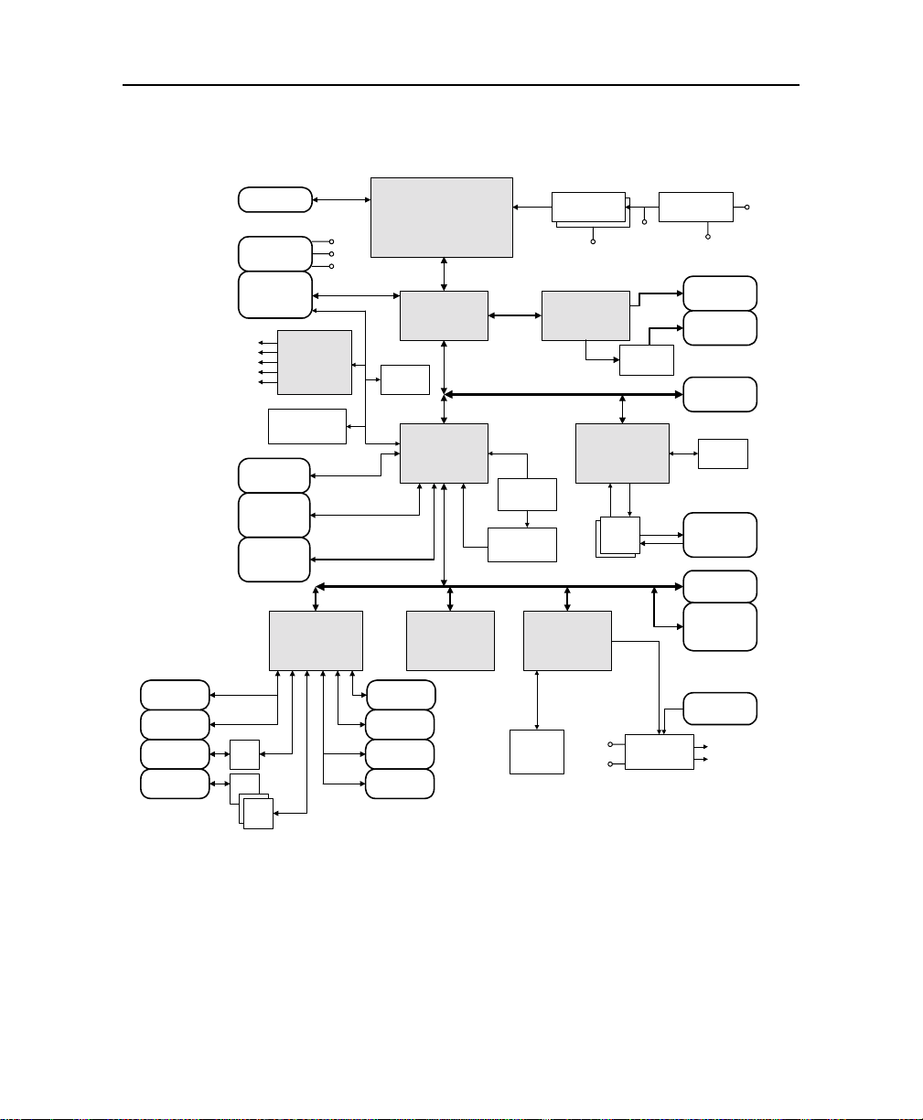
VIPer 830 Technical Reference Manual
1.2. VIPer830 – BLOCK DIAGRAM
MINI-DIN
KBD
KBD/SPKR
COM1
COM2
CPU(66/100)
PCI (33MHz)
SDRAM (66/100)
REF(14MHz)
USB (48MHz)
'211
'211
ITP TEST
EXT. POWER
CONNECTOR
SDRAM
DIMM
1 X 168p
GENERATOR
TEMPERATURE
SENSOR
INTERFACE
USB
COMPACT
FLASH
IDE
HARD DISK
ULTRA I/O
CONTROLLER
(SMC 37C67X)
211
'485
CLOCK
LINEAR
INTEL CELERON
PROCESSOR
4KB
EEPROM
SMB
PARALLEL
(PGA370)
GTL+
HA
HD
BUS
PCI/AGP
CONTROLLER
(INTEL 82443BX)
AD
AD
PCI TO ISA
BRIDGE(Piix4)
(INTEL 82371AB)
SA
SD
SA
SD
BOOT BLOCK
FLASH EPROM
(AMD 29F002)
PFO
VCC
+12
-12
MA
MD
USBP
SDD
PDD
SA
SD
VCCP
AGP
BUS
VBAT
BATTERY
3.6V
SUPERVISOR
(MAX 6306)
ISA BUS
REGULATORS
VCC2.5
SVGA
CONTROLLER
(CHIPS 69000)
PCI BUS
FAST ETHERNET
SA
SD
CPLD
(XILINX 9572)
IDCHIP
FP
CONTROLLER
10/100 Mbps
(INTEL 82559)
RX/TX
XFRM
WDRES
FLOPPY
PS/2 MOUSE
MINI-DIN
MOUSE
48-BIT
SERIAL
NUMBER
VCC
VCC3
VCC3
VCC3
RGB
BFP
LEVEL
SHIFTERS
AD
TDRD
TX
RX
SA
SD
SUPERVISOR
(MAX 6306)
SWITCHING
REGULATORS
CRT
FLAT PANEL
PC104+
DIO
EEPROM
10/100
BASE-T
ISA BUS
SLOT
PC104
8/16 BIT
RESET
PWROK
PWRGOOD
VCC
VCORE
PCI
1KB
PB
1-2
Page 13

Product Overview
The major features are summarized below:
Microprocessor Support: Celeron from Intel (PGA370).
66MHz Front Side Bus and SDRAM bus (processors at 100MHz FSB will also be
supported).
External Cache: 128KB of L2 Pipelined burst cache (internal to the CPU).
System Memory: up to 256MB of Synchronous DRAM (SDRAM), or 256MB of
SDRAM on one 168-pin DIMM sockets.
CompactFlash Disk: connects directly on the Secondary IDE interface with the
proper adapter module.
PC/104-Plus Connector: makes the board capable of driving PCI boards (requires the
T076 module and the VIPci 960 backplane).
Universal Serial Bus (USB): Supports two USB ports.
Video: Integrated AGP 64-bit CRT/Flat panel video controller with 2MB on-chip
SDRAM video memory (Intel 69000).
Fast Ethernet Controller: Supports 10/100Base-TX Ethernet interface (Intel 82559).
Operating Systems: Supports all OS developed for x86 and Pentium processors.
Boot Block Flash BIOS: 256KB device. Protected boot block section with
reprogramming capability.
1-3
Page 14

VIPer 830 Technical Reference Manual
VIPer830 – Connector and Jumper Location
1-4
Page 15
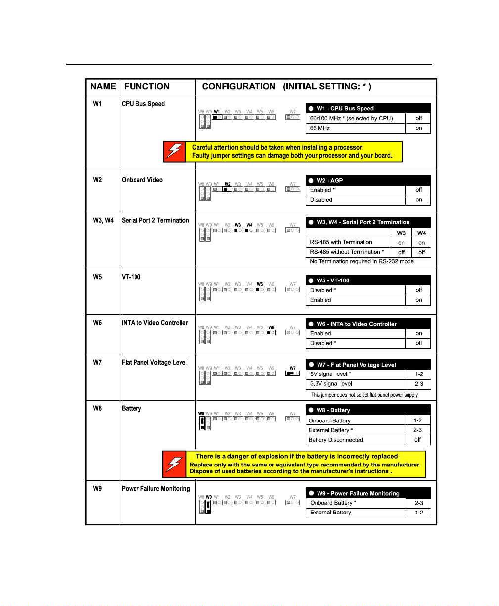
2. JUMPER SETTINGS
2-1
Page 16
R
B
p
f
3. FEATURE DESCRIPTION
Each feature of the VIPer 830 is described in the following sections.
SETUPS
3.1. CPU/SYSTEM CORE - PROCESSOR
elated Jumpers
The processor and its cooling system are factory installed, and the relative jumpers are set
according to the CPU specification.
To configure the board for another processor, use:
W1 jumper to setup the CPU bus speed
If required, the CPU Bus s peed can be forced to 66MHz. Default setup provides automatic
detection of 66/100MHz bus speed.
Jumper settings are described in the previous Section – Setting Jumpers.
IOS Level
To enable or disable the CPU internal cache, run the BIOS Setup program, BIOS Features
tion.
o
MAKING CONNECTIONS
The processor installs in the U14 sock et. Insert carefully the processor into its socket, and
make sure to match the beveled corner of the chi p surface with t he corres ponding marki ng o
the processor socket. Use a “chip-puller” or thin screwdriver to rem ove the proc essor.
The +5V fan power supply is provided on the J19 header.
MORE ...
Processors supported by the VIPer830 are specified as follows (under DOS):
V Core Normal Doze Standby Suspend
Celeron 300MHz 2.0V 3.80A 2.31A 2.20A 1.69A
Celeron 366MHz 2.0V 4.14A 2.43A 2.35A 1.74A
Celeron 433MHz 2.0V 4.38A 2.50A 2.42A 1.75A
:
3-1
Page 17

VIPer 830 Technical Reference Manual
R
B
t
3.2. CPU/SYSTEM CORE - MEMORY
One vertical DIMM socket (168 pins) is provided to support from 8MB to 256MB of
SDRAM system memory.
SETUPS
elated Jumpers
No jumper setting is required.
IOS Level
Options to setup the system memory are provided by the BIOS Setup program, Chipse
Features option.
MAKING CONNECTIONS
The memory module must be installed in the J6 socket.
1Mx64/72, 2Mx64/72, 4Mx64/72, 8Mx64/72, 16Mx64/72 and 32Mx64/72 type memory are
supported
MORE ...
The system memory must conform to the following:
. PC-100 standard, 66MHz, 3V, single-sided or double-sided DIMM
. ECC is supported
3-2
Page 18

Feature Description
R
B
3.3. CPU/SYSTEM CORE - BATTERY
The board is installed with a 3.6V, 370mAh lithium battery (22.5x5.6mm, wafer form
factor with plug-in termination).
SETUPS
elated Jumpers
To enable onboard CMOS backup, connect t he battery to the board’s circui try by setting the
W8 jumper to 1-2 position (onboard Battery).
Jumper settings are described in the previous Section – Setting Jumpers.
IOS Level
No BIOS setup is required.
MAKING CONNECTIONS
Initially, the board is shipped with the battery jumper set so as the batt ery is disconnected
from the board circuitry: W8 in position 2-3 (External Battery).
When operating with the board for the first time, the jumper must be installed in position 1-2.
When setting the board for an external battery the e xternal volt age sourc e must be applied t o
the pin 1 (or 3) of the J20 External Battery header, and the W8 jumper must be installed in
position 2-3.
MORE ...
The internal or external battery can be supervised through the onboard Power Fail Detection
function (battery voltage drops below 3.08V) using the W9 Power Failure Monitoring jumper.
For more information on the Power Fail Detection function please refer to the previous Section
- Jumper Settings and the Supervisory Feature described in this Section.
3-3
Page 19
VIPer 830 Technical Reference Manual
R
B
3.4. ETHERNET INTERFACE
The 10Base-T/100Base-TX Ethernet interface controller (Intel 82559) resides on the PCI
bus and is therefore Plug and Play by default. It is assigned with one PCI master REQ/GNT
pair.
SETUPS
elated Jumpers
No jumper setting is required.
IOS Level
The onboard Ethernet controller can be enabled/disabled through the BIOS Setup P rogram,
Integrated Peripherals option.
MAKING CONNECTIONS
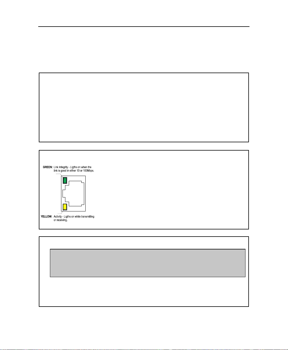
The communication link plugs into the J17 RJ -45 connector located
on the edge bracket.
10Mbps or 100Mbps network speed is automatically detected and
switched.
Link and Activity LEDs (respectively green and yellow) are built on
the connector.
The 10Base-T uses UTP (Unshield Twisted Pair) cables, category 3,
4 or 5 (5 is better).
The 100Base-TX uses UTP cable category 5 that m ust comply with
the IEEE 802.3 10Base-T standard for two pairs.
MORE ...
The network driver is contained on the diskette referred to as Intel 82S558/559,
Fast Ethernet Pro 100 / PCI. For instructions on the installation of the network
driver, please refer to the READ_NET.TXT (ASCII) or READ_NET.DOC (Word
6.0) file.
Once the proper Ethernet driver is installed, the onboard PnP BIOS and the driver
automatically allocate resources – I/O addresses, IRQ and DMA channels.
3-4
Page 20
Feature Description
R
B
3.5. I/O DEVICES – I/O CONNECTIONS
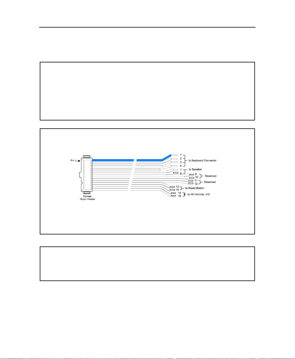
Standard AT keyboard, speaker port, reset button and hard disk LED signals are issued on
the J15 Multi-Function header. A flat cable is provided with the board for connecting the
respective devices.
SETUPS
elated Jumpers
No jumper setting is required.
IOS Level
No BIOS setup is required.
MAKING CONNECTIONS
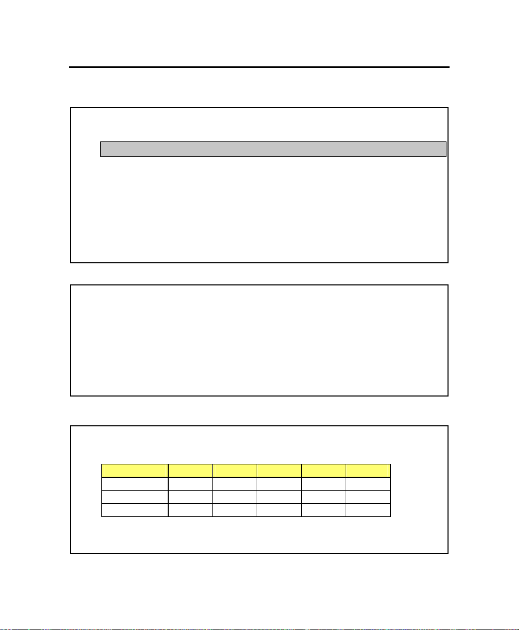
When using the #150-018-01 keyboard cable, signals are issued as follows:
To assemble you own cable, you will need: Amp 746285-3 [optional strain relief: 499252-8],
Robinson Nugent IDS-C16PK-TG, Thomas & Betts 622-1630 [optional strain relief: 622-1641],
and 16-pin flat cable connector.
MORE ...
No external limiting resistor is required while connecting the HD Activity LED. A 330-ohm
resistor is integrated onboard.
3-5
Page 21

VIPer 830 Technical Reference Manual
R
B
s
A
3.6. I/O DEVICES - KEYBOARD
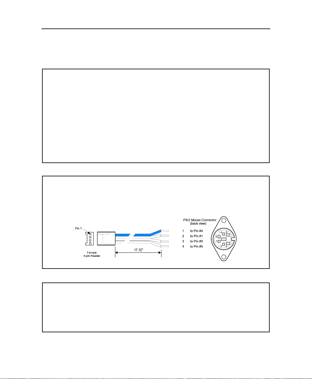
The simplest way to connect a PS/2 keyboard to the board is to use the J16 standard PS/2
keyboard connector on the edge bracket. No additional cabling is required.
SETUPS
elated Jumpers
No jumper settings are required.
IOS Level
To setup the Typematic Rate of the keyboard, run t he BIOS Setup Program, BIOS Feature
option.
MAKING CONNECTIONS
Keyboard signals are also issued on the J7 Keyboard/Speaker connector. To connect a standard
T keyboard use the #150-018-01 flat cable provided with your board (see previous page).
Do not connect two keyboards simultaneously to the board. This can damage the keyboard
interface.
MORE ...
A USB keyboard can replace the standard keyboard: the USB keyboard support must be
declared at the BIOS level (Integrated Peripherals option). This option only applies at the DOS
and BIOS level.
The keyboard interface is protected by a self-resetting fuse.
3-6
Page 22
Feature Description
R
B
3.7. I/O DEVICES – PS/2 MOUSE
The simplest way to connect a P S/2 mouse to the board is to use the J15 standard PS/2
keyboard connector on the edge bracket. No additional cabling is required.
SETUPS
elated Jumpers
No jumper setting is required.
IOS Level
The PS/2 mouse is assigned by default with the IRQ12 that is also used to wake-up the
system when entered into a power management mode. To free this interrupt from monitoring,
run the BIOS Setup program, Power Management option.
MAKING CONNECTIONS
A PS/2 mouse header (J14) is also provided onboard. To connect a mouse through this
header, a shielded PS/2 mouse adapter cable is required. It is available as 18” shielded
mouse cable, part number 150-337-00.
MORE ...
A self-resetting fuse protects the mouse interface.
3-7
Page 23
VIPer 830 Technical Reference Manual
R
B
3.8. PARALLEL PORT
The board features the bi-directional enhanced parallel port that supports the IEEE 1284
protocols including compatibility, nibble, byte EPP and ECP modes.
IRQs and addresses can be configured at the BIOS level.
SETUPS
elated Jumpers
No jumper setting is required.
IOS Level
The Parallel Port is assigned by default with the IRQ7 interrupt. To free t his interrupt from
monitoring, run the BIOS Setup program, Power Management option.
To setup the Parallel Port (I/O address, IRQ, operating mode), run the BIOS Setup Program,
Integrated Peripherals option.
MAKING CONNECTIONS
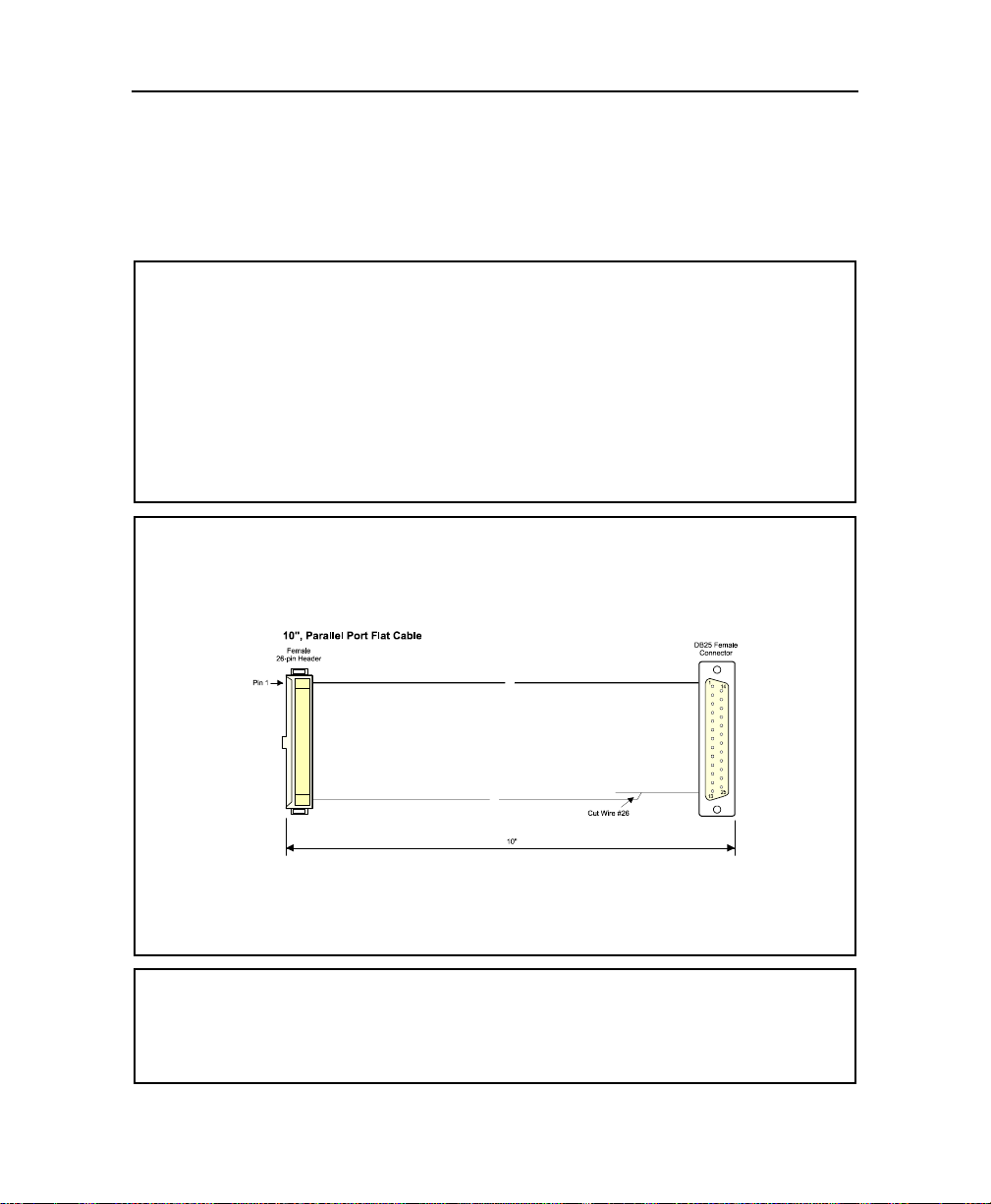
The parallel port is available through the J12 Parallel Port header. To setup the parallel port
as a standard printer port, a 26-pin header/D-Sub 25-pin adapter cable is required.
A 10” printer cable with bracket is available and is referred to as #150-172.
To assemble your own cable, you will need: Amp 746285-6 [optional strain relief: 499252-3],
Robinson IDS-C26PK-TG, Thomas & Betts 622-2630 [optional strain relief: 622-2641], and
Polarized IDC female socket connector.
MORE ...
By default, the parallel port is set for ECP+EPP 1.9 operation mode.
The signal assignation on the J12 Parallel Port connector differs depending on the operation mode.
For more information on the signal assignation, please refer to Appendix D – Connector Pinouts.
3-8
Page 24

Feature Description
R
B
s
r
3.9. PC/104, PC/104-PLUS
Standard PC/104 modules are supported through the P1/P2 PC/104 connectors.
Standard PC/104-Plus modules are supported through the combination of P1/P2 PC/104
connector set (ISA) and the P4 PC/104-Plus connector (PCI).
SETUPS
elated Jumpers
No jumper setting is required on the board.
IOS Level
No BIOS setup is required.
MAKING CONNECTIONS
Connector implementation conforms to the PC/104 and PC/104-Plus specifications.
P1 provides standard ISA signals (16 bits)
P2 provides standard ISA signals (8 bits)
P4 provides standard PCI signals (32 bits)
MORE ...
When installing both a PC/104 and PC/104-Plus modules on the board, the PC/104-Plu
module must be installed first and the PC/104 module on top of it.
PC/104-Plus modules may require setups (jumpers) bef ore being installed on the board. Fo
more information, please refer to the documentation of your module.
The PC/104-Plus interface can also be used with an expansion module to drive PCI slots.
3-9
Page 25
VIPer 830 Technical Reference Manual
R
B
y
3.10. SERIAL PORTS – SERIAL PORT 1
Serial Port 1 is available through the J10 connector and supports RS-232 operation mode.
SETUPS
elated Jumpers
No hardware setup is required.
IOS Level
The following settings are available through the BIOS Setup program:
IRQ monitoring see Power Management Setup option
Port Address/IRQ assignation see Integrated Peripherals option
MAKING CONNECTIONS
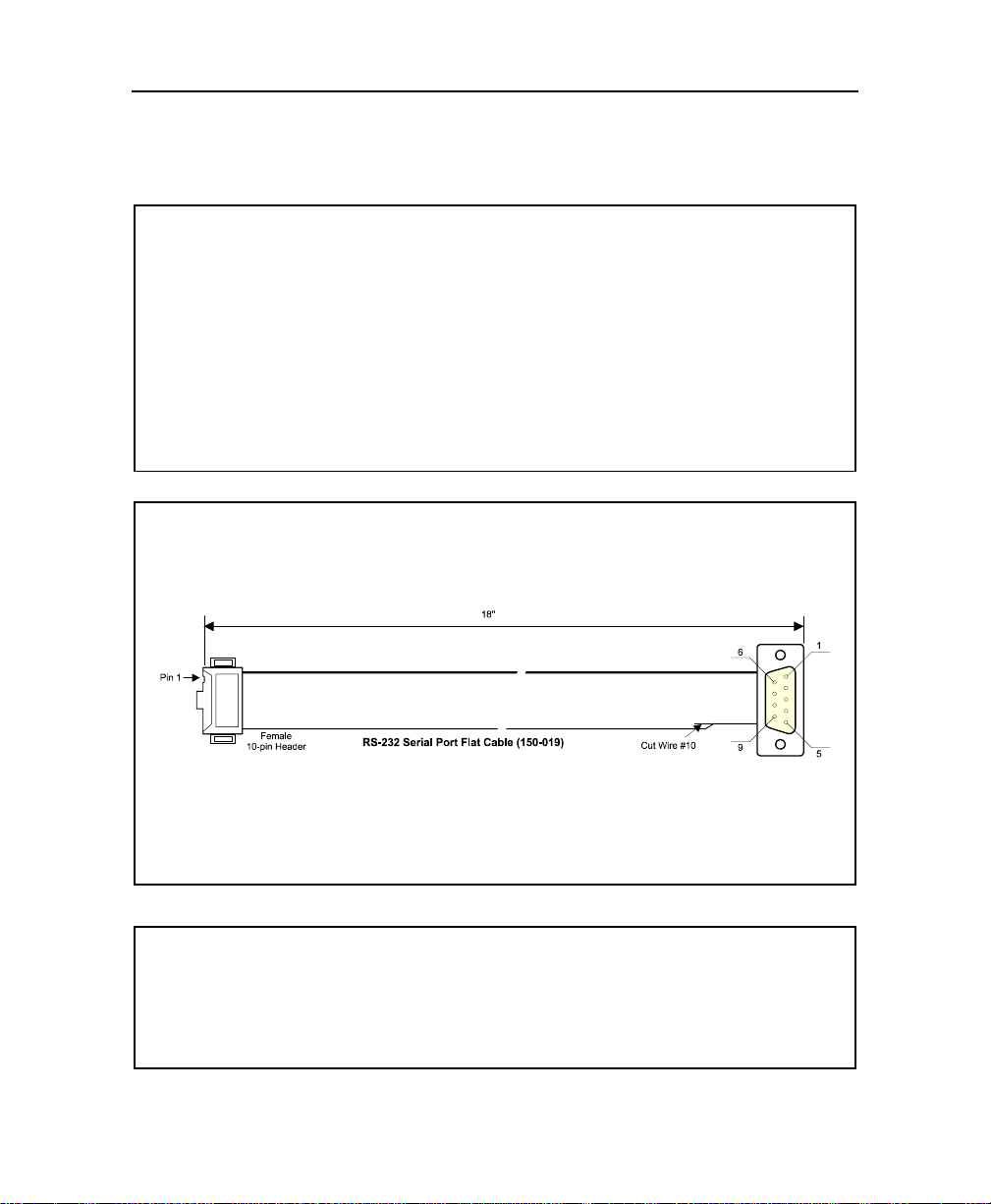
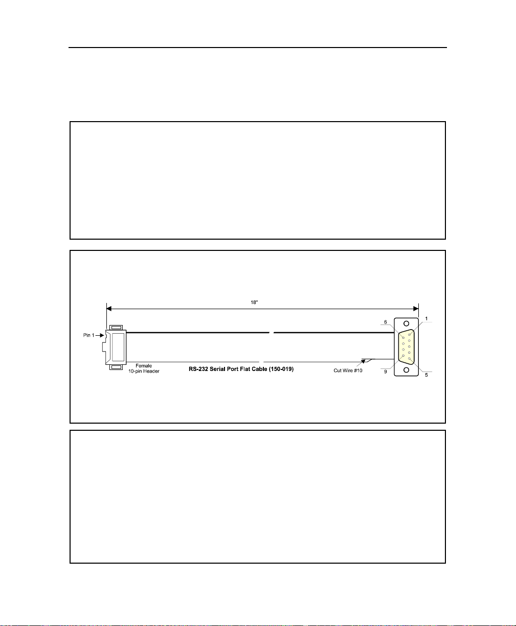
The usual way to connect a device to a serial port is to issue signals through a 10-pin
header/D-Sub 9-pin adapter cable. An 18” 10-pin header/D-Sub 9-pin adapter cable is
available and is referred to as #150-019.
To assemble your own cable, you will need: Amp 746285-1 [optional strain relief: 499252-5],
Robinson Nugent IDS-C10PK-TG, Thomas & Betts 622-1030 [optional strain relief: 622-1041],
and 10-pin flat cable connector
.
MORE ...
Since adapter cables are provided from various sources, the pinout is often different. The
direct crimp design offered allows the simplest cable assembly. All cables are available b
contacting the Sales Department.
3-10
Page 26
Feature Description
R
B
r
e
3.11. SERIAL PORTS – SERIAL PORT 2
Serial Port 2 is available through the J13 connector and supports both RS-422/RS-485 and
RS-232 operation modes.
SETUPS
elated Jumpers
If required, for RS-485 mode operation, termination resistors can be tied to the RX and TX
pairs of the Serial Port 2 by shorting respectively the W3 and W4 jumpers.
IOS Level
The following settings are available through the BIOS Setup program:
IRQ monitoring see Power Management Setup option
Port Address/IRQ assignation see Integrated Peripherals option
Port Mode see Integrated Peripherals option
MAKING CONNECTIONS
The usual way to connect a device to a serial port is to issue signals through a 10-pin
header/D-Sub 9-pin adapter cable. An 18” 10-pin header/D-Sub 9-pin adapter cable is
available and is referred to as #150-019.
To assemble your own cable, you will need: Amp 746285-1 [optional strain relief: 499252-5],
Robinson Nugent IDS-C10PK-TG, Thomas & Betts 622-1030 [optional strain relief: 622-1041],
and 10-pin flat cable connector.
MORE ...
In RS-485 mode, the Serial Port 2 supports either full-duplex or party line operation:
Full-Duplex – upon power-up or reset, the COM2 interface circ uits are automatically set fo
full-duplex operation. Pins 3 and 4 of J 13 ac t as the receiver li nes and pins 5 and 6 act as t he
transmitter line.
Party Line – to enable party line operation, s et the bit 2 of I/O port 190h (or 290h or 390h,
depending on the I/O base address value – see BIOS Setup program, Chipset Featur
option). The transceiver lines (pins 3 and 4 of J13) will be controlled by t he RTS signal. Upon
power-up or reset, the transceiver is by default in “receiver mode” to prevent online
perturbations. If the board is placed at one end of t he network, use W3 and W4 jumpers to
enable the termination resistors.
3-11
Page 27
VIPer 830 Technical Reference Manual
R
B
y
d
3.12. STORAGE DEVICES – CompactFlash
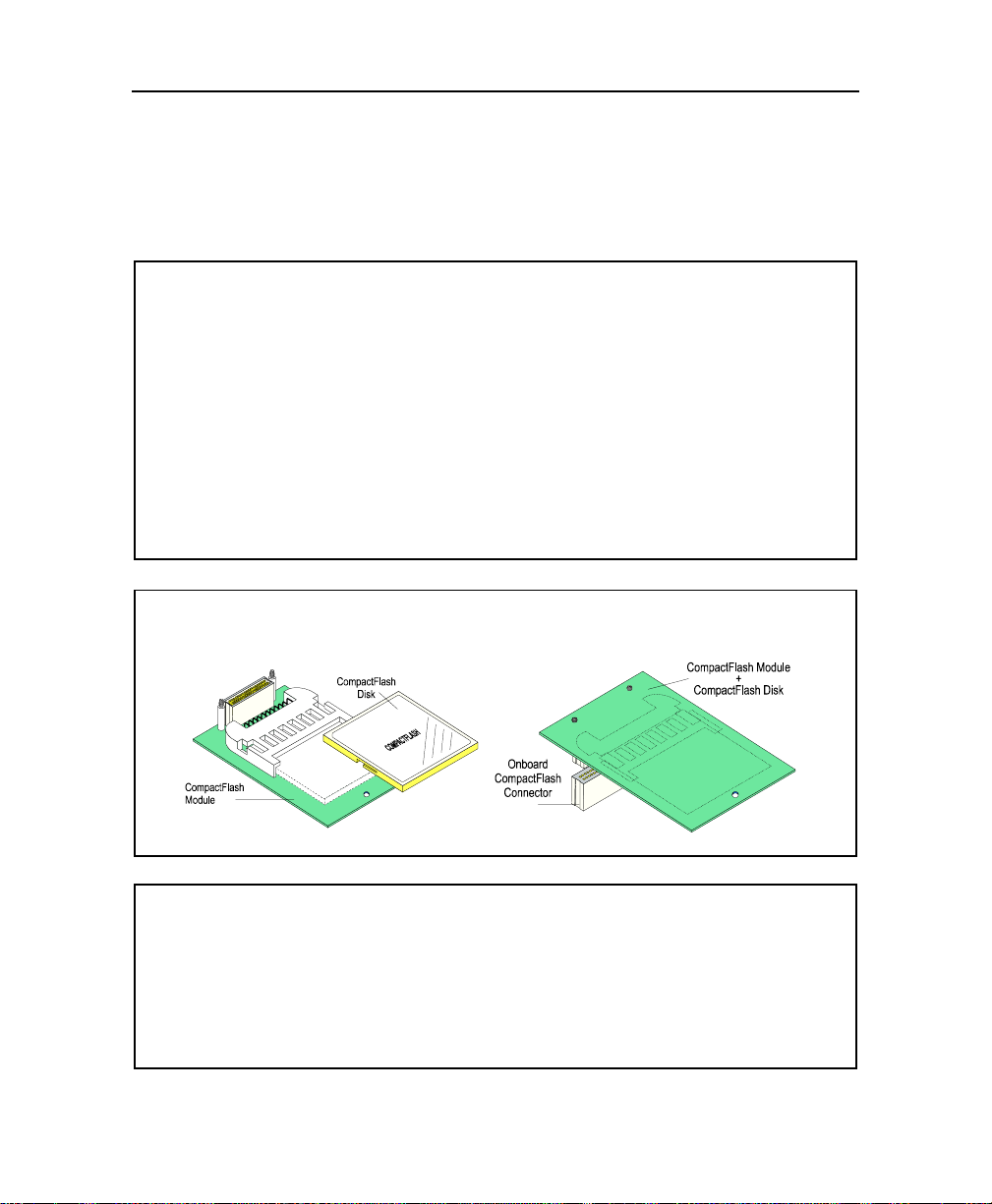
A CompactFlash disk consists of a CompactFlash device and a CompactFlash module that
supports it.
The CompactFlash module connects to the board through the P3 CompactFlash connector.
SETUPS
elated Jumpers
No jumper setting is required.
IOS Level
Since the CompactFlash disk is IDE c ompliant, i t requires no s oftware driver. It is tied direct l
to the Secondary IDE interface.
The CompactFlash disk specifications are automatically detect ed at the BIOS level – Standar
CMOS Setup.
MAKING CONNECTIONS
The CompactFlash assembly and mounting are presented below:
MORE ...
The CompactFlash disk is bootable as a standard IDE disk unit. To select the boot sequence,
refer to Section 4 – BIOS Features Setup.
3-12
Page 28
Feature Description
R
B
t
3.13. STORAGE DEVICES – FLOPPY DISK DRIVE
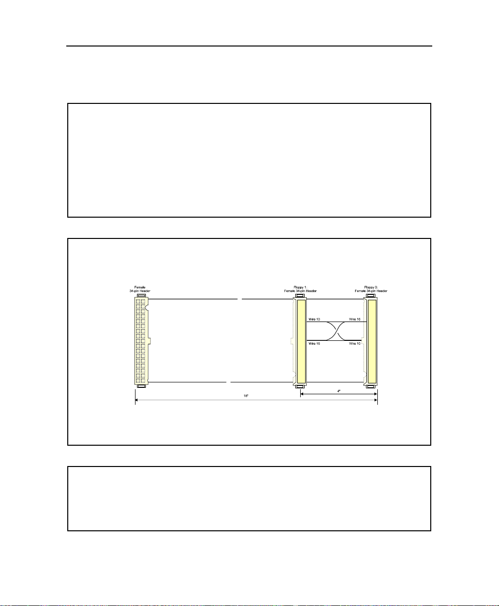
The floppy disk interface supports up to two drives through the J2 Floppy connector.
Connecting a floppy disk drive requires a standard IBM 34-pin floppy disk cable.
SETUPS
elated Jumpers
No jumper setting is required.
IOS Level
The floppy disk controller can be disabled at the BIOS level, Integrated Peripherals option.
To setup the floppy disk drive installation, refer to the Standard CMOS Setup option.
To protect the floppy disk against write accesses, refer to the BIOS Features Setup option.
MAKING CONNECTIONS
A standard IBM 34-pin adapter cable is required to connect a floppy disk drive. An 18” fla
cable is available and is referred to as #150-051.
To assemble your own cable, you will need: Amp 746285-8 [optional strain relief: 499252-6],
Robinson Nugent IDS-C34PK-TG, Thomas & Betts 622-3430 [optional strain relief: 622-3441],
and 34-pin flat cable connector.
MORE ...
The connector located at the opposite of the connector that plugs into the Floppy Disk Drive
connector of the board carries signals for the boot drive (Floppy 0). It is recognized as
Floppy Disk A by the BIOS. The other connector is reserved to the Floppy Disk B.
3-13
Page 29
VIPer 830 Technical Reference Manual
R
B
3.14. STORAGE DEVICES – HARD DISK DRIVE
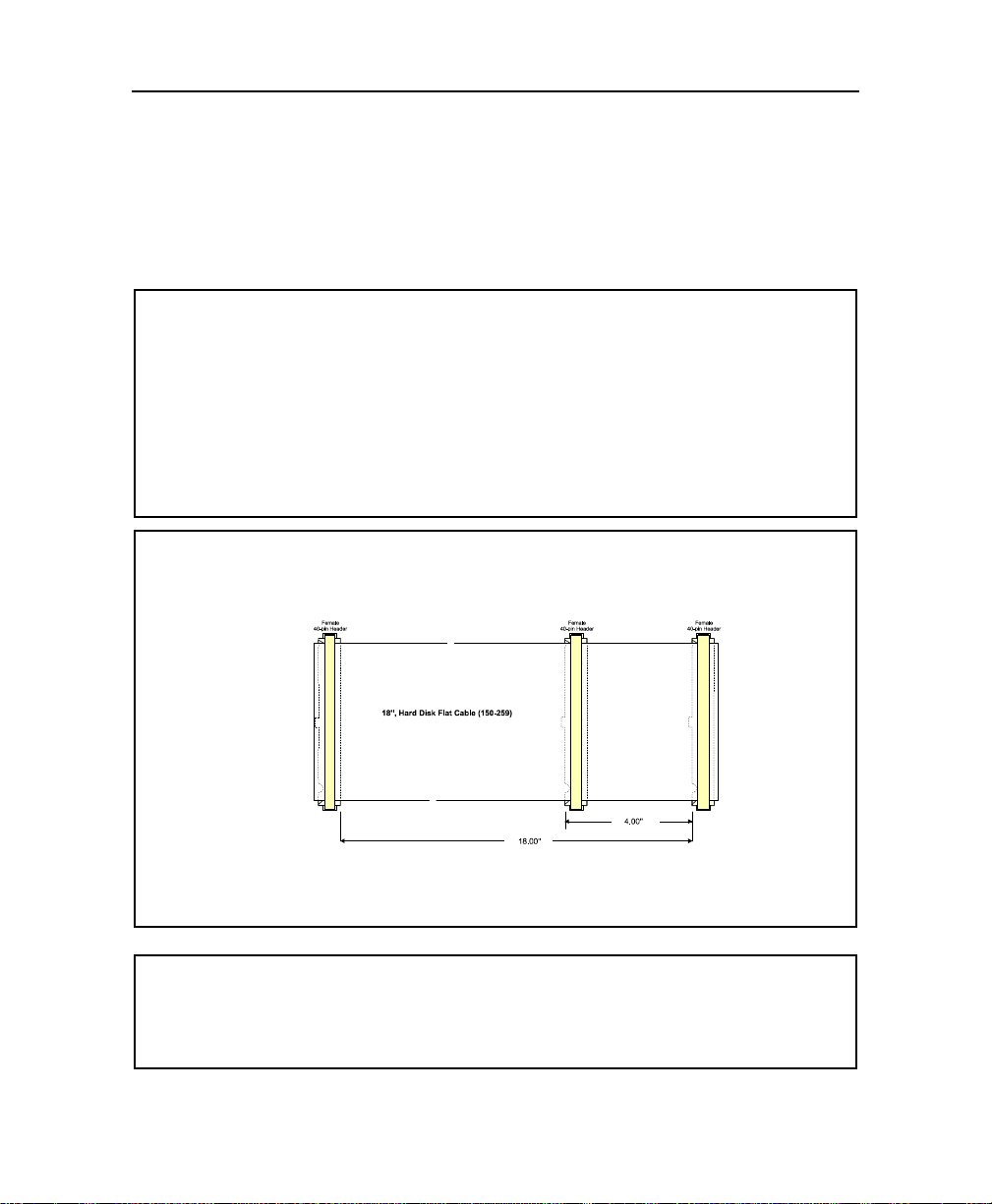
The board supports up to two hard disk drives through the J1 IDE connector (Primary
interface), in Master/Slave configuration. Connecting a hard disk drive requires a standard
IBM 40-pin hard disk cable.
SETUPS
elated Jumpers
No jumper setting is required.
IOS Level
Standard setups are provided at the Standard CMOS Setup option.
To setup the disk boot sequence, refer to the BIOS Features Setup option.
Other setups are provided at the Integrated Peripherals Setup option
MAKING CONNECTIONS
A standard IBM 40-pin adapter cable is required to connect a hard disk drive. An 18” flat cable
is available and is referred to as #150-259.
To assemble you own cable, you will need: AMP 746285-9 [optional strain relief: 499252-1],
Robinson Nugent IDS-C40PK-TG, Thomas & Betts 622-4030 [optional strain relief: 622-4041],
and 40-pin flat cable connector
.
MORE ...
When installing two hard disks, both are connected in parallel. The recognition between
Master and Slave device is provided by the jumper settings supported on the devices.
3-14
Page 30
Feature Description
R
B
3.15. SUPERVISION FEATURES – SUPERVISOR REGISTERS
Three 8-bit supervisor registers (x90h-x92h) are provided to set and control special I/O
features of the board. These registers can be assigned with three consecutive and
relocatable addresses.
SETUPS
elated Jumpers
No jumper setting is required.
IOS Level
The base address of the first supervisor register (x90h) can be selected within 190h,
290h, or 390h. Registers 1 and 2 are located at the s u bs equent addres s es .
To select the Base Address, use the Chipset Features, Supervisor Base Address option.
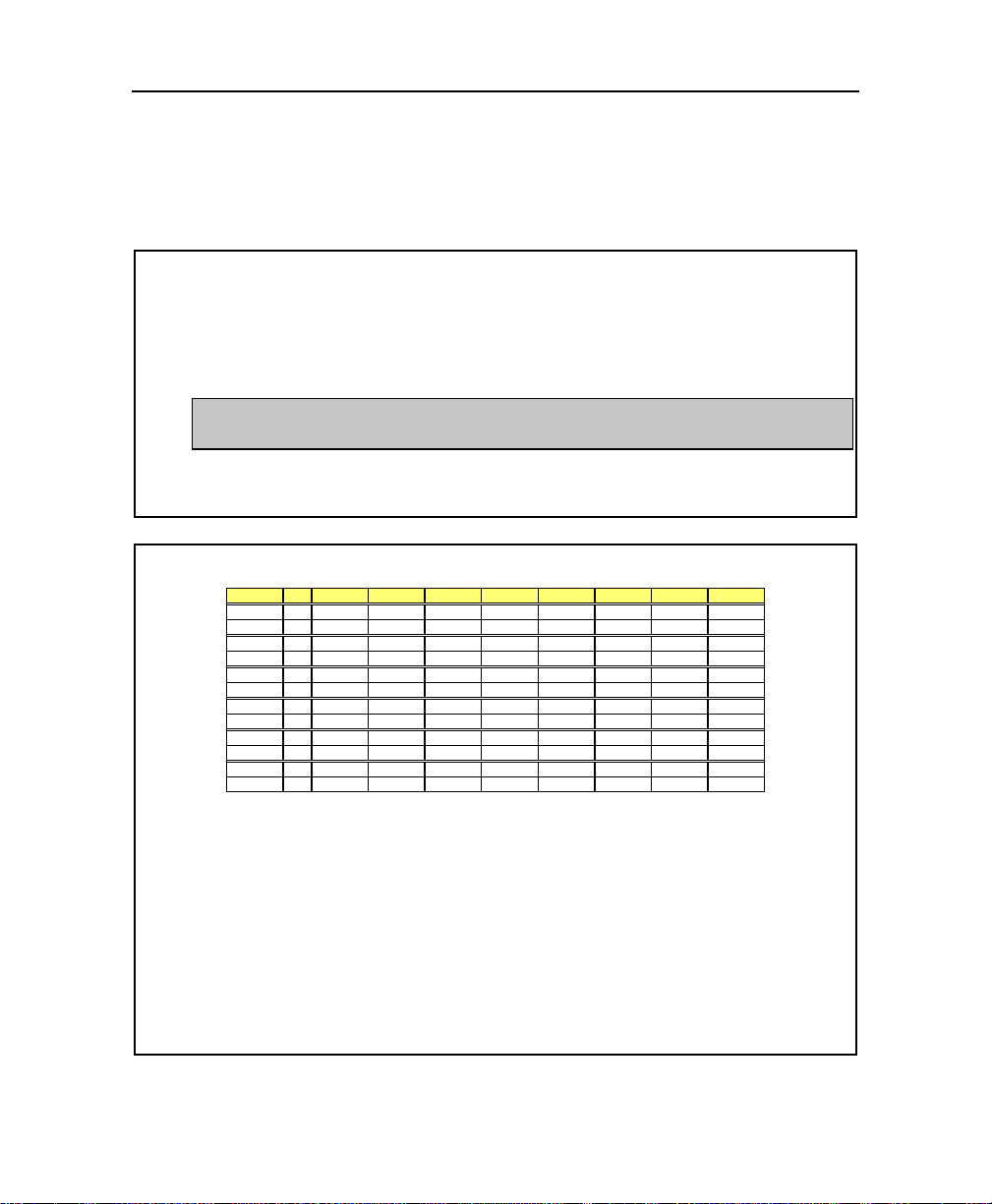
SUPERVISIOR REGISTERS
Address R/W D7 D6 D5 D4 D3 D2 D1 D0
x90h R - - - RS485 RS232 ST1 - -
x90h W - - - RS485 RS232 ST1 - -
x91h R PBRST - WD0 - - - - -
x91h W - - - - - - - -
x92h R - - - - - LOCK - CLRHIS
x92h W - - - - - LOCK - CLRHIS
x93h R - GPIO2 GPIO1 IDCHIP - I2C_CLK I2C_DATA
x93h W - GPIO2 GPIO1 IDCHIP - I2C_CLK I2C_DATA
x96h R WDEN WDD2 WDD1 WDD0 - - - -
x96h W WDEN WDD2 WDD1 WDD0 - - - -
x97h R BATFEN BATFLT - - - - WDNMIEN WDNMI
x97h W BATFEN - - - - - EDNMIEN -
RS232 Enables the UART2 RS232 operation.
RS485 Enables the UART2 RS422 & 485 operations.
ST1 Enables the RTS2 signal to be used as 485TX ENABLES when in 485 mode.
PBRST Push button reset history status.
WDO Watchdog reset history status.
LOCK A 1 locks the state of the enable bit for the programmable watchdog.
CLRHIS A 0 clears all history bits.
GPIO[2:1] General purpose I/O. Open collector output.
IDCHIP One-wire clock/data for silicon ID chip.
WDEN Digital watchdog enable. Can be forced active by jumper.
WDD[2:0] Duration of digital watchdog.
BATFEN Enables the NMI for a battery fault.
BATFLT NMI from the local RTC battery monitoring.
WDNMIEN Enables the NMI from the watchdog (stage 2).
WDNMI NMI from the watchdog timeout.
3-15
Page 31

VIPer 830 Technical Reference Manual
R
r
B
3.16. SUPERVISION FEATURES – POWER FAIL DETECTION
The Power Fail Detection feature can be used to monitor a po wer failure condition that
could be initiated by either the onboard battery or an external power source (W9 jumper).
SETUPS
elated Jumpers
Refer to W9 Power Fail jumper to select the power source to be monitored (onboard battery o
external).
IOS Level
No setting required.
OPERATION
The power fail status is available through bit 7 (BATFEN) of the Supervisor Register x97h
The bit is trigged from High to Low when the power source that is controlled drops below a
threshold:
. 3.08V, when the onboard battery voltage is controlled
. A user-defined value when an external battery placed under the control of the board.
The user-defined threshold is determined by a resistor divider made of R20 (10Kohm)
and R5 to be installed by the user.
ula to calculate the value of R5: R5 = 1KΩ. (Vext –1.25)/1.25
Use the J20 External Battery connector to connect an external battery to the board.
3-16
Page 32

Feature Description
R
B
3.17. SUPERVISION FEATURES – POWER MANAGEMENT
All power management controls and setups are provided at BIOS level.
SETUPS
elated Jumpers
No jumper setting is required.
IOS Level
All setups are provided at the BIOS level, refer to the BIOS Setup program description.
OPERATION
The board supports three levels of power management:
Doze mode – after a selected period of system inactivity, the CPU clock runs at lower
speed while all other devices still operate at full speed.
Standby mode – after entering Doze mode, and a selected period of system inactivity has
elapsed, the fix disk drive and the video shut off while all other devices still operate at a full
speed.
Suspend mode – after entering Standby mode, and a selected period of system inactivity
has elapsed, all devices except the CPU shut off.
The power management can be resumed by an IRQ assigned to the modem (when used). An
activity of the assigned IRQ always awakens the system.
The hard disk drive can be powered down while all other devices remain active. The HDD
Power-down mode is only available if the device supports this capability.
3-17
Page 33
VIPer 830 Technical Reference Manual
R
B
3.18. SUPERVISION FEATURES – DIGITAL WATCHDOG
The board provides a digital watchdog whic h monitors t he p rocesso r’s inactivit y and issu es
a failure signal if the processor fails to refresh the watchdog within a timeout period (1.6
seconds).
SETUPS
elated Jumpers
No jumper setting is required.
IOS Level
No setting required.
OPERATION
When operating with the watchdog, be aware of the following:
1. Unlock the WDEN bit by writing a '0' to the bit D2 of the register x92h. Write the bits D7
to D4 in the register x96h to enable the digital watchdog. Lock the WDEN bit by writing
a '1' to the bit D2 of the register x92h.
2. To refresh the watchdog, write any value to register x96h.
3. The VIPer830 is equipped with a circuit t hat can inform the user of the cause for the last
system reset. The reset can be caused by an action on the push-button reset or a timer
elapsing:
The bit D7 of the register x91h is set high if the last system reset was caused by the reset
push-button.
The bit D5 of the register x91h is set high if the last system reset was caused by the
watchdog timer elapsing.
Writing a '0' to the bit D0 at x92h clears these bits.
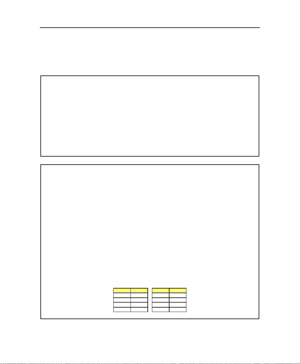
To set the value of the digital watchdog, refer to the following table and the WDD[2:0] bits (see
Supervisor Register x96h)
Value Delay Value Delay
000 15.625ms 100 4s
001 62.5ms 101 16s
010 250ms 110 64s
011 1s 111 256s
3-18
Page 34
Feature Description
R
B
3.19. USB PORT
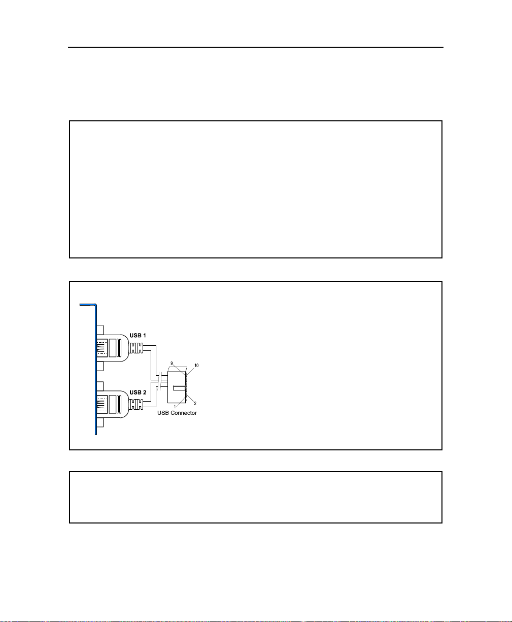
The VIPer830 provides a dual USB port through the J9 USB connector. To conform to the
standard USB requirements, a USB adapter cable is required.
SETUPS
elated Jumpers
No jumper setting is required.
IOS Level
To assign an IRQ to the USB port refer to the PnP / PCI Configuration option.
To connect an USB keyboard, run the B IOS Setup Program, Chipset Features option, and
enable the USB keyboard support. This option is only supported at the BIOS and DOS level.
MAKING CONNECTIONS
A 10-pin header/Dual USB adapter cable with bracket is
available and is referred to as #150-316.
MORE ...
Each channel’s supply pin is protected by a self-resetting 1A fuse.
3-19
Page 35

VIPer 830 Technical Reference Manual
R
B
r
t
3.20. VIDEO FEATURES – CRT DISPLAY
Analog RGB VGA signals are available for direct CRT display connection through the J11
VGA CRT connector located on the edge bracket.
SETUPS
elated Jumpers
To disable the onboard video controller, install a jumper cap on the W2 jumper.
IOS Level
The CRT Only operation mode must be set at the BIOS level , Standard CMOS Setup option.
Other configurations are: Flat Panel Only, or simultaneous CRT/Flat Panel (both).
MAKING CONNECTIONS
The CRT monitor connects directly to the VIPer830 through the J11 VGA CRT connecto
located on the edge bracket.
MORE ...
In simultaneous CRT/Flat Panel mode (same applicat ion on both the CRT and the flat panel
displays), the resolution of the CRT display is imposed by t he resolution selected for t he fla
panel display (See the Flat Panel description on the next page).
3-20
Page 36

Feature Description
R
B
t
r
r
3.21. VIDEO FEATURES – FLAT PANEL DISPLAY
The flat pane l con nects to the VI Per 830 thr ough the J 5 Flat Pane l connec tor. A cable must
be designed to tie the panel to the board in accordance to the pinout of both the board and
the panel connectors.
SETUPS
elated Jumpers
The flat panel voltage level can be selected within 3.3V to 5V by using the W7 jumper.
IOS Level
Run the BIOS Setup Program, Standard CMOS Setup option to configure the board to suppor
a flat panel display.
MAKING CONNECTIONS
The pinout of the onboard flat panel connector is provided in Appendix D.
When designing an application including a flat panel, ensure the video BIOS supports the
panel you have chosen. For more information on flat panels and their connecti on, please ref e
to our web site (Support and Services, V ideo BIOS page), or do not hesitate to contact ou
Technical Support Department.
50-pin High Density Flat Panel Connector Assembly is available and is referred to as #150-105.
Otherwise, you may purchase the connector by ordering one these parts: Adam Tech HFCS-50SG
(Connector only), Hirose HIF6-50D-1.27R (Connector only), Oupiin 102-50GB1 (Connec t or only).
MORE ...
WARNING
It is recommended not to exceed a maximum length of 18” when des igning a flat panel cable.
Though some flat panels may support a longer cable, it is the customer’s responsibility to
ensure that the additional length is fully supported by the panel’s specification.
3-21
Page 37

A
RT
SOFTWARE SETUPS
4. BIOS SETUP PROGRAM
5. UPGRADING THE BIOS WITH UBIOS
6. VT100 MODE
P
Page 38

4. BIOS SETUP PROGRAM
To run the AWARD Setup program incorporated in the ROM BIOS proceed as follows:
1. Turn on or reboot the system.
2. Hit the DELETE key before or when the message - "
appears near the bottom of the screen.
3. The main menu appears on the screen.
The following options are available:
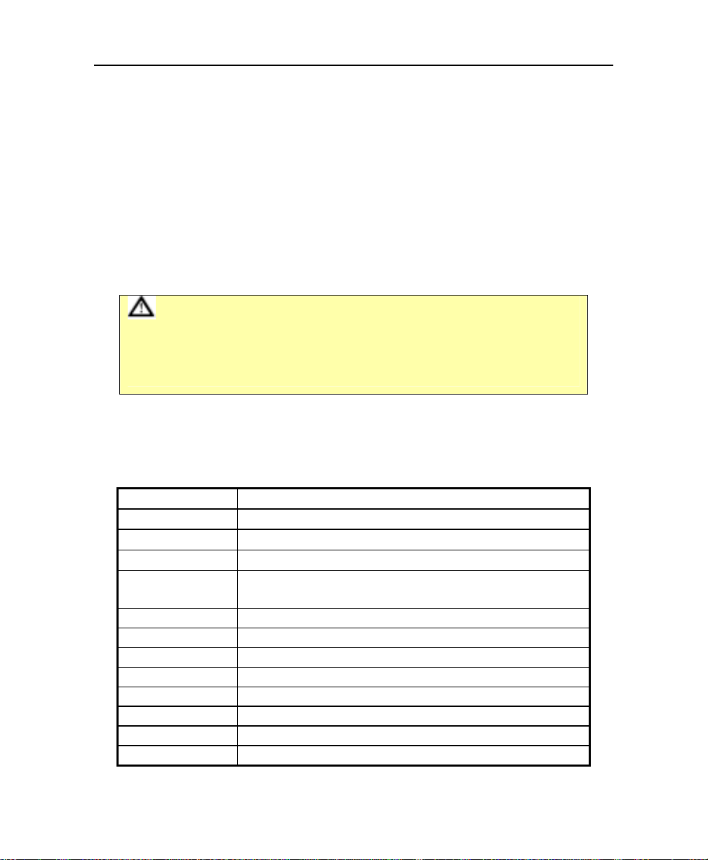
Option Description
Standard CMOS Setup
BIOS Featur es Set up
Chipset CMOS Setup
Power Manag. Setup
PnP/PCI Configuration
CPU / Board Feature Setups
Integrated Peripherals
Supervisor/User Password
Setting
IDE HDD Auto Detection
Load Bios Defaults (Safe)
Load Setup Defaults
(Optimal)
Save and Exit
Exit without Saving
This Setup page includes all the items in a standard, AT-compatible BIOS
(date, time, hard disk type, floppy disk type, video adapter type, memory…).
Use this screen to set all the items of special enhanced features of AWARD.
Use this screen to set all the items of the chipset’s special features.
Use this screen to set power conservation options.
Use this screen to set plug and play and PCI configuration options.
Features that are related to the capability of the board to manage the
watchdog and the temperature of the CPU.
I/O subsystems that depend on the integrated peripheral controllers in your
system.
Change, set, or disable password. It allows you to limit access to the system
and the Setup, or just to the Setup.
Automatically detect and configure IDE hard disk parameters.
The BIOS defaults are fail safe settings that consist of the safest set of
parameters. Use them if the system is behaving erratically. They should
always work but do not provide optimal system performance.
The Setup defaults are optimal settings that provide optimum performance
for all devices and system features. If CMOS RAM is corrupted, the Setup
defaults are loaded automatically.
Use this option to save the configuration in CMOS and Flash memory.
Exits the AWARD Setup without saving the configuration to CMOS
RAM.
PRESS DEL TO ENTER SETUP"
4-1
Page 39
VIPer 830 Technical Reference Manual
Whenever you are not sure about a certain setting, refer to the list of default values. Default
values are provided in the event that a value has been changed and one wishes to restore
the original values.
Loading the BIOS or SETUP defaults will affect all the options and will reset options
previously altered. Loading default values at the main menu changes setups for all screens
while loading default values in a particular setup screen will affect only that screen.
BIOS default settings consist of the safest set o f parame ters. Use it if the s ystem is beha ving
erratically. They should always work but do not provide an optimal system performance.
SETUP default values provide an optimum performance for all devices and system features.
CAUTION
Before modifying CMOS setup parameters, ensure that the Battery jumper
is installed (See Setting Jumpers Section).
The board is capable of operating without the onboard battery if the
CMOS values are saved into the Flash memory.
4.1. BASIC COMMANDS
Operations within each menu and screen are summarized below:
Up arrow (↑↑↑↑)
Down arr ow (↓↓↓↓)
Left arrow (←←←←)
Right arrow (→→→→)
Esc key
PgUp key
PgDn key
+ key
- key
F5 key
F6 key
F7 key
F10 key
Move to previous item.
Move to next ite m.
Move to the ite m to th e le f t.
Move to the ite m to th e r i g h t.
In Main Menu: Quit settings with saving options.
In sub-menus: Exit and return to Main Menu.
Increase the numeric value or make changes.
Decrease the numeric value or make changes.
(Numeric keypad) Increase the numeric value or make changes.
(Numeric keypad) Decrease the numeric value or make changes.
Restore the previous setup values.
Load the default setup values from BIOS Default Table.
Load the setup values from the Setup Default Table.
Save all the CMOS changes.
4-2
Page 40

BIOS Setup Pro gram
4.2. STANDARD CMOS SETUP
This part of the setup allows you to set the time, date, hard disk type, types of floppy drives
and video type.
Date/Time
Hard Disks
Drive A / Drive B
Video
CRT & LCD
Halt On
The current values for each category are displayed.
Two IDE controllers are implemented (Primary and Secondary); each
supports two disks (Master Disk and Slave Disk).
Selects the category identifying the types of floppy disk dri ve A or drive B
that have been installed in the computer.
This option specifies the basic type of display adapter card installed in the
system.
Indicates whether the CRT only, LCD only or Both display modes are
selected.
This option specifies the type of the error that will stop the system during
the BIOS booting procedure. When an error occurs, the corresponding
message is displayed. Press F1 to continue or DEL to enter into the BIOS
setup program. The settings are: All errors, No errors, All but keyboard,
All but diskette, and All but disk/key (default setting).
4-3
Page 41

VIPer 830 Technical Reference Manual
4.3. BIOS FEATURES SETUP
Option
Virus Warning Dis. Dis. En. / Dis. When Enabled, you receive a warning message if a program
Quiet POST Dis. Dis. En./Dis.
Quick Power On Self
Test
Full Screen Logo
Show
Boot from LAN First Dis. Dis. En./Dis.
Raid Card Boot First Dis. Dis. En./Dis.
Boot Sequence A,C,
Swap Floppy Drive Dis. Dis. En./Dis.
Boot Up Floppy Seek En. Dis. En./Dis.
Drive A Boot Permit En. En. En./Dis. When Disabled, this option will not permit booting from Drive A.
Floppy Disk Access
Control
BIOS
Setup Defaults
Defaults
Dis. En. En./Dis.
Dis. Dis. En./Dis.
SCSI
R/W R/W
C,A,
SCSI
Possible
Settings
A,C,SCSI;
C,A,SCSI;
C,CDROM,A;
CDROM,C,A;
D,A,SCSI;
E,A,SCSI;
F,A,SCSI;
SCSI,A,C;
SCSI,C,A;
C only;
LS/ZIP,C.
R/W,
Read Only
Description
(specifically, a virus) attempts to write to the boot sector or the
partition table of the hard disk drive. You should then run an antivirus program. Keep in mind that this feature protects only the
boot sector, not the entire hard drive.
Note: Many disk diagnostic programs and OS setups (e.g.,
Win95 setup), that access the boot sector table, can trigger
the virus-warning message. If you plan to run such a
program, we recommend that you first disable the virus
warning.
At the power on self-test (POST), only the AWARD logo and the
“Press DEL to enter SETUP” message appears.
Select Enabled to reduce the amount of time required running the
POST. A quick POST skips certain steps. We recommend that
you enable quick POST to save time, since most major OS do
their own tests
When enabled, a full screen bitmap (BMP) picture will appear
during the POST or you can have your logo being displayed.
Contact the technical Support (see Appendix G).
If Enabled, the BIOS will first attempt to boot from the LAN. The
complete procedure for this function is available on the “Boot from
LAN” utility CDROM.
If Enabled, the BIOS will first attempt to boot from the RAID disk
card.
This option defines the searching order in the BIOS for the boot
device(s).
Note: The Boot from LAN First and Raid Card Boot First
options take precedence over this option.
Selecting Enabled assigns physical drive B to logical drive A, and
physical drive A to logical drive B.
When Enabled, the BIOS tests (seeks) floppy drives to determine
whether they have 40 or 80 tracks. Only 360K B floppy drives ha ve 40
tracks; drives with 720KB, 1.2MB, and 1.44MB capacity al l have 80
tracks. Because very fe w modern PCs ha ve 40 t rack fl opp y dri ves, we
recommend that you set this field to “Disabled” to save time.
When Read Only, this option will not permit writing to the floppy
disk.
4-4
Page 42

BIOS Setup Pro gram
BIOS FEATURES SETUP (CONTINUED)
Option
Report No FDD For
Win 95
Hard Disk Write
Protect
HDD S.M.A.R.T.
Capability
Delay For HDD (Secs) 0 0 0-15
OS Select For DRAM
> 64MB
Gate A20 Option Norm. Fast Normal, Fast
Security Option Setup Setup Setup, Normal
Diskette Access For All Al l All, Supervisor
Boot Up NumLock
Status
Typematic Rate
Setting
Typematic Rate
(Chars/s)
Typematic Delay
(msec)
Comport 1 1 1,2 Use this option to select which COM port will be used for VT100
Speed Auto Auto
Parity None None
Data 8 8 7, 8 Use this option to specify the number of data bits being used.
Stop 1 1 1, 2 Use this option to specify the number of stop bits being used.
BIOS
Defaults
Setup
Defaults
No No Yes, No
Dis. Dis. En./Dis. When Enabled, this option will not permit writing to the hard disk.
Dis. En. En./Dis.
Non-
Non-
OS/2
OS/2
On On On, Off
Dis. En. En./Dis.
30 30
250 250 250-1000 ms
Possible
Settings
Non-OS/2,
OS/2
6-30
char/sec.
VT100 Settings
Auto, 2400,
9600, 19200,
38400, 57600,
115200
None, Odd,
Mark, Even,
Space
Description
Select Yes to release IRQ6 when the system contains no floppy
drive, for compatibility with Windows 95 logo certification. In the
Integrated Peripherals screen, select NO on the Onboard FDC
Controller option.
When Enabled, the Self-Monitoring, Analysis, and Reporting
Technology (S.M.A.R.T.) features of the HDD are supported.
S.M.A.R.T is used for prediction of device degradation and/or
faults.
This number of seconds inserted prior to HDD i nitialization. 0 is
disabled.
Select OS2 only if you are running OS/2 with greater than 64MB of
RAM.
When Fast, enables fast switching of Gate A20 via the 440BX
chipset, instead of the keyboard controller.
If you have set a password, select whether the password is
required every time the system boots (“System” opti on), or only
when you enter Setup (“Setup” option).
When this option is set to Supervisor and the Security option to
System, all floppy disk accesses (read/write) are limited to the
Supervisor (supervisor password required).
Controls the state of the NumLock key when the system boots.
When set to “On”, the numeric keypad generates numbers instead
of controlling cursor operations.
When Disabled, the following two items (Typematic Rate and
Typematic Delay) are irrelevant. Keystrokes repeat at a rate
determined by the keyboard controller in your system. When
Enabled, you can select a typematic rate and a typematic delay.
When the typematic rate setting is Enabled, you can select a
typematic rate (the rate at which characters repeat when you hold
down a key).
When the typematic rate setting is Enabled, you can select a
typematic delay (the delay before keystrokes begin to repeat when
you hold down a key).
Select the baud rate off the COM port. used in VT100 mode.
Use this option to select the parity.
4-5
Page 43

VIPer 830 Technical Reference Manual
4.4. CHIPSET FEATURES SETUP
Option BIOS
CPU Internal Cache Dis. En. En./Dis. Enables or Disables the CPU Internal Cache (L1 cache).
External Cache Dis. En. En./Dis. Enables or Disables the External Cache (L2 cache).
CPU L2 Cache ECC
Checking
(on CuMine PIII
processor, you cannot
disable ECC)
SDRAM RAS-to-CAS
Delay
SDRAM RAS
Precharge Time
SDRAM CAS Latency
Time
SDRAM Precharge
Control
DRAM Data Integrity
Mode
Memory Hole At 15M16M
System BIOS
Cacheable
Video BIOS
Cacheable
Video RAM Cacheable Dis. En. En./Dis.
8 Bit I/O Recovery
Time
16 Bit I/O Recovery
Time
Defaults
Setup
Defaults
Dis. En. En./Dis. Enables or Disables ECC Checking for L2 cache.
3 3 2, 3
3 3 2, 3
3 3 2, 3
Dis. Dis. En./Dis.
Non-
ECC
ECC
Dis. Dis. En./Dis.
Dis. En. En./Dis.
Dis. En. En./Dis.
3 1 1-8, NA
2 1 1-4, NA
Possible
Settings
ECC,
Non-ECC
Description
Note: processors provided by Kontron support ECC.
However, not all Pentium® II processors support ECC. Check
Intel’s website to know if your processor supports ECC:
http://developer.intel.com/support/
processors/pentiumII/identify.htm
Note: Upon boot-up, the BIOS will detect and display the optimal
value for the SDRAM options (three options in this menu), if it is
differ en t fr om th e Se tu p v a lu e. Y ou m u st en t er th e A WA RD Se tu p,
and set the options at the suggested value if you want the best
performance.
This option inserts a timing delay between the CAS and RAS strobe
signals, used when SDRAM is written to, read from, or refreshed. The
number selected is the number of clocks to be inserted between a row
activates command and either a read or write command.
Selects the number of CPU clocks for the RAS precharge. If an
insufficient number of cycles are allowed for the RAS to accumulate its
charge before SDRAM refresh, the refresh may be incomplete and the
DRAM may fail to retain data.
This option controls the number of clocks between when a read
command is sampled by the SDRAMs and when the chipset samples
read data from the SDRAMs. Select 3 for 3 DCLKs and 2 for 2 DCLKs.
If a given row is populated with a registered SDRAM DIMM, an extra
clock is inserted between the read command and when the chipset
samples read data.
When Enabled, all CPU cycles to SDRAM result in an All Banks
Precharge Command on the SDRAM interface.
When set to ECC, allows auto-correction of the data read from
memory. The ECC error flags’ status register and the error pointer are
updated if error correction occurs in this mode.
When set to Non-Ecc, no error checking or error reporting is done.
You can reserve this area of system memory for ISA adapter ROM.
When this area is reserved, it cannot be cached. The user information
of peripherals that need to use this area of system memory usually
discusses their memory requirements.
Selecting Enabled allows caching of the system BIOS ROM at F0000hFFFFFh, resulting in better system performance. However, if any
program writes to this memory area, a system error may occur.
Selecting Enabled allows caching of the video BIOS ROM at C0000h
plus the VGA BIOS size, resulting in better video performance.
However, in any program writes to this memory area, a system error
may occur.
When Enabled, video memory region is cacheable. Some off-board
video card drivers may behave strangely; in such a case, disable this
option.
The I/O recovery mechanism adds bus clock cycles between PCIoriginated I/O cycles to the ISA bus. This delay takes place because the
PCI bus is much faster than the ISA bus. These two fields let you add
recovery time (in bus clock cycles) for 8-bit and 16-bit I/O.
.
4-6
Page 44

CHIPSET FEATURES SETUP (CONTINUED)
Option BIOS
PCI/VGA Palette
Snoop
Passive Release En. En. En./Dis.
Delayed Transaction Dis. Dis. En./Dis.
Supervisor I/O Base
Address
Power-Supply Type AT ATX AT, ATX This option selects the type of power supply.
AGP Aperture Size
(MB)
Video BIOS Shadow Dis. En. En./Dis.
C8000-CBFFF Dis. En. En./Dis.
CC000-CFFFF Dis. En. En./Dis.
D0000-D3FFF Dis. En. En./Dis.
D4000-D7FFF Dis. En. En./Dis.
D8000-DBFFF Dis. En. En./Dis.
DC000-DFFFF Dis. En. En./Dis.
Defaults
Setup
Defaults
Dis. Dis. En./Dis.
190h 190h
64 64 4 to 256 This option selects the size in MB of the AGP Aperture.
Possible
Settings
190h, 290h,
390h
Description
Palette snooping allows multiple VGA devices operating on
different buses to handle data from the CPU on each set of palette
registers.
When set to Enabled, data read and written by the CPU is
directed to both the PCI VGA device’s palette registers and the
ISA VGA device’s palette registers, permitting the palette registers
of both to be identical.
When set to Disabled, data read and written by the CPU is only
directed to the PCI VGA device’s palette registers.
When Enabled, CPU to PCI bus accesses are allowed during passive
release otherwise the arbiter only accepts another PCI master access
to local SDRAM .
The chipset has an embedded 32-bit posted write buffer to support
delay transactions cycles. Select Enabled to support compliance with
PCI specifications version 2.1.
This option determines the base address for the Supervisor I/O
Register, which is used for such functions as power fail detection
and the watchdog timer.
Software that resides in a read-only memory (ROM) chip on a
device is called firmware. Award permits shadowing of firmware
such as the system BIOS, video BIOS, and simi lar operating
instructions that come with some expansion peripherals.
Shadowing copies from ROM into system RAM, where the CPU
can read it through the 64-bit DRAM bus. Firmware not shadowed
must be read by the system through the 8 or 16-bit ISA bus.
Shadowing improves the performance of the system BIOS and
similar firmware for expansion peripherals.
Enable shadowing into each section of memory separately. Many
system designers hardwire shadowing of the system BIOS and
eliminate a System BIOS Shadow option. Note that on a PCI VGA
card (on board or off-board), the VGA BIOS is always shadowed.
Video BIOS shadows into memory area C0000 plus the VGA
BIOS size. The remaining areas between C0000 and DFFFF
shown on the BIOS Features Setup screen may be occupied by
other expansion card firmware. If an expansion peripheral in your
system contains ROM-based firmware, you need to know the
address range the ROM occupies to shadow it into the correct
area of RAM.
BIOS Setup Pro gram
4-7
Page 45

VIPer 830 Technical Reference Manual
4.5. POWER MANAGEMENT SETUP
Option BIOS Defaults Setup
ACPI Function Dis. Dis. En./Dis. The Advanced Configuration and Power Interface (ACPI) allows
Power
Management
PM Control by
APM
Video Off Method V/H SYNC
Video Off After Standby Stand
Modem Use IRQ 3 3 N / A , 3 , 4, 5 , 7 ,
Doze Mode Dis. Dis Disable
Standby Mode Di s. Dis. Disable
Suspend Mode Dis. Dis. Disable
HDD Power Down Dis. Dis. Disable
HDD Down When
Suspend
Throttle Duty Cycle 75.0% 75.0% 12.5%-75.0% When the system enters Doze mode, the CPU clock runs only part of
PCI/VGA
Act-Monitor
Soft-OFF by PWRBTTN
User Def. User
Instant-off Instant-off Instant-off,
Defaults
Def.
Yes Yes Yes, No If Yes, the OS will control the PM by APM calls. If No, the BIOS
V/H SYNC
+
Blank
En. En. En./Dis. When Enabled and the system goes in Suspend Mode, the hard disk is
Dis. Dis. En./Dis. When Enabled, continuous video activity restarts the global timer for
+
Blank
by
Possible
Settings
User Define,
Min Saving,
Max Saving
Blank Screen
V/H
SYNC+Blank,
DPMS,
NA, Suspend,
Standby, Doze,
9, 10, 11
1min to 1h
1min to 1h
1min to 1h
1-15min
Delay 4 sec.
Description
Operating System Direct Power Management (OSPM) and make
advanced configuration architectures possible.
When Enabled, the OS supports ACPI or OSPM (e.g., Win98,
Window NT 5).
Note: When Enabled, no other option in the Power
Management Setup will be used.
This option allows you to select the type (or degree) of power
saving for Doze, Standby, and Suspend modes.
Max Saving: Maximum power savings. Inactivity period is 1
minute in each mode.
Min Saving: Minimum power savings. Inactivity period is the
maximum setting in each mode (1 hour for Doze, Standby and
Suspend).
User Define: Set each mode individually. Select time-out periods
in the PM Timers section (see below).
will control the PM and APM calls from the OS will be ignored.
Determines the manner in which the monitor is blanked.
V/H SYNC + Blank: System turns off vertical and horizontal
synchronization ports and writes blanks to the video buffer.
DPMS Support: Select this option if your monitor supports the Display
Power Management Signaling (DPMS) standard of the Video
Electronics Standards Association (VESA). Use the software supplied
for your video subsystem to select video power management values.
Blank Screen: System only writes blanks to the video buffer.
As the system moves from lesser to greater power-saving modes,
select the mode in which you want the monitor to blank.
Name the IRQ line assigned to the modem (if any) on your system.
Activity of the selected IRQ always awakens the system.
After the selected period of system inactivity (1 minute to 1 hour), the
CPU clock ru ns at low er spee d wh ile all o th er d evic es s till o per at e at full
speed.
After entering Doze mode and the selected period of system inactivity
(1 minute to 1 hour) has elapsed, the video shuts off while all other
devices st ill operate at full speed.
After entering Standby mode and the selected period of system
inactivity (1 minute to 1 hour) has elapsed, all devices including the
CPU shut off and the system waits for an event to wake them up again.
After the selected period of drive inactivity (1 to 15 minutes), the hard
disk drive powers down while all other devices remain active. The HDD
power down mode is o nly availa ble if th e ha rd drive has this ca pabilit y.
shut down.
the time. You may select the percentage of time that the clock does not
run.
Standby mode.
This option only works with an ATX power supply. It allows two
configurations for the power button: Instant-off for power supply on/off
switch, or Delay 4 sec. for entering Suspend Mode after pressing the
button at least 4 seconds.
…
4-8
Page 46

BIOS Setup Pro gram
POWER MANAGEMENT SETUP (CONTINUED)
Option BIOS
Resume by Ring Dis. En. En./Dis. When Enabled and a modem is connected to a COM port, allows a
IRQ 8 Break Suspend Dis. En. En./Dis. When Enabled, the RTC alarm interrupt is monitored to allow an
Resume by Alarm Dis. Dis. En./Dis. When Enabled, allows setup of a time to re-activate the CPU when in
IRQ[3-7,9-15], NMI Dis. En. En./Dis.
Primary IDE 0 Dis. En. En./Dis.
Primary IDE 1 Dis. En. En./Dis.
Secondary IDE 0 Dis. En. En./Dis.
Secondary IDE 1 Dis. En. En./Dis.
Floppy Disk Dis. En. En./Dis.
Serial Port En. En. En./Dis.
Parallel Port Dis. En. En./Dis.
Defaults
Reload Global Timer Events:
Setup
Defaults
Possible
Settings
Description
modem ring to re-activate the CPU when in Suspend mode.
interrupt to awaken the system when in Doze, Standby or Suspend
Mode.
Suspend mode with the options Date (of Month) Alarm and Time
(hh:mm:ss) Alarm.
Note: The IRQ 8 Break Suspend option in this setup screen must
be Enabled to use the RTC alarm.
When any of the options below is Enabled, monitoring of the interrupt
will occur to a llow an in te rru pt t o awa ken the s ystem w hen in Do ze,
Standby or Suspend Mode.
4-9
Page 47

VIPer 830 Technical Reference Manual
4.6. PnP/PCI CONFIGURATION
Option BIOS
PnP OS Installed Yes No Yes, No If the operating system (OS) is Plug and Play (for example
Resources Controlled
By
Reset Configuration
Data
IRQ n Assigned To PCI/ISA
DMA n Assigned To PCI/ISA
Init Display First Onboard Onboard PCI Slot,
Assign IRQ For VGA Dis. Dis. En./Dis. When Enabled, the video card is assigned an IRQ.
Assign IRQ For USB En. En. En./Dis. When Enabled, the USB is assigned an IRQ. When Disabled, the
PCI Latency Timer 32 32 0-255
Special PCI Routing En. En. En./Dis. Disable this option if the backplane into which the board is
Slot [number] Use IRQ
No.
Used MEM Base
Address
Defaults
Setup
Defaults
Auto Man. Auto, Man. The Award Plug and Play BIOS can automatically configure all the
Dis. Dis. En./Dis. Normally, you leave this field Disabled. Select Enabled to reset
PCI/ISA
PnP
PnP
PCI/ISA
PnP
PnP
Auto Auto Auto, 3, 4, 5,
N/A N/A N/A,
Possible
Settings
PCI/ISA PnP,
Legacy ISA
PCI/ISA PnP,
Legacy ISA
Onboard,
AGP (not
supported)
(integers)
7, 9, 10, 11,
12, 14, 15
C800, CC00,
D000, D400,
D800, DC00
Description
Windows 95), select “Yes” if you want the OS to allocate
resources according to Plug and Play standards, or “No” if you
want the same resource allocations at every system boot-up.
Select “No” when the OS is not Plug and Play (for example, DOS).
Note: When set to “Yes”, only the boot devices will get an
IRQ.
boot and Plug and Play-compatible devices. If you select Auto, all
the interrupt requests (IRQs) and DMA assignment fields
disappear, as the BIOS automatically assigns them.
Extended System Configuration Data (ESCD) when you exit
Setup if you have installed a new add-on and the system
reconfiguration has caused such a serious conflict that the
operating system cannot boot.
When resources are controlled manually, assign each system
interrupt as one of the following types, depending on the type of
device using the interrupt:
Legacy ISA: Devices compliant with the original PC AT bus
specification, requiring a specific interrupt, such as IRQ4 for serial
port 1.
PCI/ISA PnP: Devices compliant with the Plug and Play standard,
whether designed for PCI or ISA bus architecture.
When Legacy ISA is selected for an IRQ line, this resource will not
be available for PCI /ISA PnP.
When resources are controlled manually, assign each system
DMA channel as one of the following types, depending on the type
of device using the interrupt:
Legacy ISA: Devices compliant with the original PC AT bus
specification, requiring a specific DMA channel.
PCI/ISA PnP: Devices compliant with the Plug and Play standard,
whether designed for PCI or ISA bus architecture.
When Legacy ISA is selected for a DMA channel, this resource
will not be available for PCI/ISA PnP.
Initializes the specified video display. The chosen display
becomes the primary display. Other display devices are ignored
by the BIOS and configured by the OS.
IRQ is freed up for another purpose.
This option specifies the value of the Latency Timer for the PCI
bus master, in units of PCI bus clocks. Value must be a power of
2 (1, 2, 4, 8, 16, 32, 64, or 128).
installed conforms to the PICMG specifications. When enabled the
board will attempt to detect a special PCI routing configuration.
When Auto, the BIOS automatically assigns an IRQ for the
specified PCI slot number (in the option title: 1, 2, 3 or 4). When
set to one of the numbers (in possible settings), that IRQ number
is assigned to the PCI slot.
Select a base address for the memory area used by any
peripheral that requires high memory.
4-10
Page 48

BIOS Setup Pro gram
4.7. CPU/BOARD FEATURES SETUP
Option BIOS
Current Processor(s)
Speed
Front Side Bus Speed
Thermal Management Options:
Thermal Management Dis. Dis. En./Dis.
Thermal Audio Alarm Dis. Dis. En./Dis.
CPU 1 Die Temp °C
Resume Alarm (°C)
Overheat Alarm (°C)
CPU Local Temp°C
Save CMOS in Flash Dis. Dis. En./Dis.
Watchdog Timer Dis Dis En./Dis.
Watchdog After POST - - En./Dis. This option enables Watchdog circuit after the POST sequence
Watchdog Duration
(ms)
Defaults
262144 64 to 262144
Setup
Defaults
Various, depending on
the installed CPU
- - Varies
42 42 10-70
50 50 30-90
- - Varies
Possible
Settings
Description
This option displays the current processor speed.
This option displays the current FSB speed.
When this option is enabled, the CPU temperature is monitored.
Whenever the CPU overheats, the CPU slows down to lower the
temperature.
When the Thermal Management option and this option are
enabled, a continuous audible alarm is sounded when the
temperature specified in the Overheat Alarm options is reached.
Such an alarm may not be supported by the Operating System.
Displays the current die (internal) CPU temperature, when
Thermal Management is enabled.
The CPU will be slowed down (Doze mode) when it reaches the
selected Overheat Alarm (°C) temperature.
Full speed (Normal mode) will be resumed when the temperature
comes down to the selected Resume Alarm (°C) temperature.
A minimu m of + 4° is automatically ensured for the Overheat
Alarm temperature with reference to the Resume Alarm.
Displays the current case (external) CPU temperature, when
Thermal Management is enabled.
Saving CMOS memory content into Flash Memory will prevent to
loose CMOS options when battery fails.
Use this option to setup duration time (in ms) of the Watchdog
timing circuitry.
4-11
Page 49

VIPer 830 Technical Reference Manual
4.8. INTEGRATED PERIPHERALS
Option BIOS
On-Chip Primary/ PCI IDE: En. En. En./Dis.
IDE Primary Master PIO
IDE Primary Slave PIO
IDE Secondary Master PIO
IDE Secondary Slave PIO
IDE Primary Master UDMA
IDE Secondary Master
UDMA
IDE Primary Slave UDMA
IDE Secondary Slave
UDMA
On-Chip Secondary PCI
IDE:
IDE HDD Block Mode Dis. En. En./Dis.
Onboard PCI SCSI Chip En. En. En./Dis.
Ethernet Controllers #1, #2 En. En. En./Dis.
USB Keyboard Support Dis. Dis. En./Dis.
PS/2 Mouse Function
Control
Onboard FDC Controller En. En. En./Dis.
Onboard Serial Port 1/2 Auto Auto
Serial Port 2 Mode RS-232 RS-232
Onboard Parallel Port 378/IRQ7 378/IRQ7
Parallel Port Mode
ECP Mode Use DMA 3 3 1, 3 Select a DMA channel for the port.
Defaults
EPP1.9
Setup
Defaults
Auto Auto
Dis. Auto Auto, Disabled.
En. En. En./Dis.
Auto Auto Auto/Dis.
ECP
ECP
+
EPP1.9
Possible Settings Description
Auto,
Modes
0-4
Dis., 3F8/IRQ4,
2F8/IRQ3, 3E8/IRQ4,
2E8/IRQ3, Auto
RS-232,RS-422,
and RS-485
Disabled, 3BC/IRQ7,
378/IRQ7, 278/IRQ5,
SPP, EPP1.9+SPP,
ECP, ECP+EPP1.9,
+
Normal, EPP1.7+SPP,
ECP+EPP1.7
Select Enabled to activate the
Primary/Secondary IDE channel. The four
options below appear only if the On-Chip
Primary option is enabled.
Use this option to set a PIO mode (0-4) for each
of the onboard IDE devices. Modes 0 through 4
provide successively increased performance
and speed. In Auto mode, the system
automatically determines the best mode for
each device. If you select a mode that the drive
does not support, it may not work, so choose a
lesser value or Auto to see the best mode for
the drive.
Ultra DMA/33 implementation is possible only if
your IDE hard drive supports it and the
operating environment includes a DMA driver
(Windows 95 OSR2 or a third-party IDE bus
master driver). If your hard drive and your
system software both support Ultra DMA/33,
select Auto to enable BIOS support.
Select Enabled to activate the Secondary IDE
channel. The four options below appear only if
the On-Chip Secondary option is enabled.
Block mode is also called block transfer,
multiple commands, or multiple sector
read/write. If your IDE hard drive supports block
mode (most new drives do), select Enabled for
automatic detection of the optimal number of
block read/writes per sector the drive can
support.
Enables/disables the onboard SCSI controller.
Enables/disables the onboard Ethernet
controller.
This option is for DOS and BIOS support only
(Win 95 has it is own drivers). It does not
enable or disable the USB controller.
When set to Auto, the PS/2 mouse is
automatically enabled, if it is present.
Select Disabled to disable the onboard floppy
disk controller (FDC).
Select a COM port address and IRQ# for the
first and second serial ports.
Select the operation mode for Serial Port 2.
Select a LPT address and IRQ# for the physical
parallel (printer) port.
Select an operating mode for the onboard
parallel port. Select ECP or EPP unless you are
certain both your hardware and software does
not support ECP or EPP mode.
4-12
Page 50

5. UPDATING THE BIOS WITH UBIOS
5.1. UBIOS.EXE 4.1 - BIOS UPDATE AND COPY UTILITY
IMPORTANT
This utility is used to update the BIOS on Kontron's single board computer. To ensure
the success of this operation, please read entirely these instructions before using this
program.
You can run this utility in 2 different modes:
1. Interactive Mode: In this mode the pr o gram is menu-driven. This mode is explained in
Section 4.2.4.
2. B a tch Mod e: It is also possible to run the program without menus by a command,
which specifies the selected options and files with parameters. This mode is explained
in Section 4.2.5.
5.2. HOW TO DO A SUCCESSFUL UPDATE
UBIOS needs to be run in DOS 3.3 or higher or compatible environment.
1. Take note of your special BIOS options such as drive settings, hard disks and custom
settings. After the update, these options will be set to their default values and all
changes will need to be re-entered.
2. Ensure you have the proper BIOS file required to execute the update.
These files may be obtained from Kontron WEB site, by Kontron technical support or
by UBIOS itself.
Refer to the 'How to do a Successful Copy' for details about the last source.
3. Boot in a driver free environment. No Hi-memory driver must be loaded.
To boot with a free environment, follow these steps:
• In DOS:
Boot with the F5 key pressed, this will disable config.sys and autoexec.bat
interaction.
• In Windows 9x:
Boot with the F8 key pressed and choose 'safe mode command prompt only'
option.
4. Call the UBIOS program and follow the instruction menu. To do a complete BIOS
update, select item 'A) Update all BIOS'.
5-1
Page 51

VIPer 830 Technical Reference Manual
5.3. HOW TO DO A SUCCESSFUL COPY
Follow the same procedure as above.
To do a complete BIOS copy, select item 'a) Copy all BIOS'.
Advanced functionality
Advanced functionality is resumed in the UBIOS help mode.
To call UBIOS help page, use UBIOS /?
VT-100 mode
UBIOS can be used without a screen in Kontron's VT-100 mode. This mode transfers all
screen and keyboard text activity through the serial port.
To use UBIOS in vt-100, use the /vt argument like: UBIOS /vt
In this mode, scan code keys are not transmitted. These keys include the 'home', 'end', 'Pg
Up', 'Pg Dn' keys that can be useful to UBIOS. To bypass this limitation, the numerical
keypad can be used.
'7' will be assigned to 'home',
'8' to the up arrow,
'9' to 'Pg Dn'
…
'5' will be assigned to the 'Esc' key.
5-2
Page 52

Updating the BIOS with UBIOS
l
5.4. UBIOS – INTERACTIVE MODE
To run th e pr o gram in interactive m o de, type "UBIO S" from the DOS prompt an d the UBIOS
4.0 presentation screen will be displayed. To continue, hit any key on the keyboard. This
brings you to the main menu.
5.4.1 Main Menu
The main menu appears below:
Write Flash BIOS device
Write Flash BIOS device
Write Flash BIOS deviceWrite Flash BIOS device
Update ALL BIOS
Update ALL BIOS Copy ALL BIOS
Update ALL BIOSUpdate ALL BIOS
Update VGA BIOS
Update VGA BIOS
Update VGA BIOSUpdate VGA BIOS
Update SCSI B IOS Copy SCSI BIO S
Update LAN BIOS Copy LAN BIOS
[ESC]
[ESC]----QUIT
QUIT
[ESC][ESC]
QUITQUIT
UBIOS 4.1
UBIOS 4.1
UBIOS 4.1UBIOS 4.1
Retrieve a BIOS to a file
Copy VGA BIOS
This option will replace the entire content of Flash BIOS with a .BIN file.
This option will replace the entire content of Flash BIOS with a .BIN file.
This option will replace the entire content of Flash BIOS with a .BIN file.This option will replace the entire content of Flash BIOS with a .BIN file.
Note: Pleas e refer t o the UPD ATING BIOS sec tion of Technic al Refer ence Ma nual fo r furt her
Note: Pleas e refer t o the UPD ATING BIOS sec tion of Technic al Refer ence Ma nual fo r furt her
Note: Pleas e refer t o the UPD ATING BIOS sec tion of Technic al Refer ence Ma nual fo r furt her Note: Pleas e refer t o the UPD ATING BIOS sec tion of Technic al Refer ence Ma nual fo r furt her
details abou t the d iffere nt UBIOS m enu opt ions.
details abou t the d iffere nt UBIOS m enu opt ions.
details abou t the d iffere nt UBIOS m enu opt ions.details abou t the d iffere nt UBIOS m enu opt ions.
5-3
Page 53

VIPer 830 Technical Reference Manual
The main menu displays two groups o f options: Write Flash BIOS device and Retrie ve a
BIOS to a file. The first gro up allo ws you to update t he Flash BIOS device with a BIOS file
stored on disk. The second group allows you to copy the contents of the Flash BIOS device to
files on disk.
In the above menu, the option Update ALL BIOS is highlighted and the option is described
in the shaded row below. Move the arrow keys to highlight other options.
To select the highlighted option, press ENTER.
To exit the program, press the ESC key when you are in the main menu.
There are four types of BIOS files appearing on the main menu:
1. ALL BIOS File: This file combines all BIOS files contained in the Flash BIOS device in
a single file. It has the .BIN extension.
2. VGA BIOS File: This file contains the VGA BIOS section of the Flash BIOS. There are
two possible types of VGA BIOS files: files with the .VGA extension (supports CRT
displays only) and files with the .BF P extension (su pports CRT and Flat Pan el displays).
3. SCSI BIOS File: This file contains the SCSI BIOS section of the Flash BIOS. It has t he
.BIN or .SCS extension .
4. LAN BIOS File: This file contains the LAN BIOS section of the Flash BIOS. It has the
.BIN extension.
5-4
Page 54

Updating the BIOS with UBIOS
5.4.2 Updating the Flash BIOS
If you select one of the Update options from the main menu, a screen similar to the
following is displayed:
You are currently using:
You are currently using:
You are currently using:You are currently using:
VIPer830
VIPer830
VIPer830VIPer830
MAIN BIOS VERSION: 0.0.1
Current directory is:
Current directory is:
Current directory is: Current directory is:
Searching for file:
Searching for file: *.bin
Searching for file: Searching for file:
File Number
File Number –––– SELECT
File Number File Number
File:
File:
File:File:
1111---- ALL.BIN
ALL.BIN
ALL.BIN ALL.BIN
SELECT [ES C]
[ESC] –––– Quit this menu Drive lette
SELECT SELECT
[ESC] [ES C]
MAIN BIOS VERSION: 0.0.1
MAIN BIOS VERSION: 0.0.1MAIN BIOS VERSION: 0.0.1
C:
C:\\\\
C:C:
*.bin
*.bin*.bin
Quit this menu Drive letter to change drive.
Quit this menu Drive lette Quit this menu Drive lette
Documentation: NOT AVAILABLE
Documentation: NOT AVAILABLE
Documentation: NOT AVAILABLEDocumentation: NOT AVAILABLE
r to change drive.
r to change drive.r to change drive.
Files of the type you selected in the main menu and which are in the current directory are
displaye d in the Fi le window.
To change directory, t ype the drive letter . If there ar e any files of the type you selected in t his
directory, they will be displayed in the File window.
5-5
Page 55

VIPer 830 Technical Reference Manual
The Documentation window displays “NOT AVAILABLE”. It will be used in the future for
displaying the contents of a .doc file.
If you want to return to the previous menu, press the ESC key.
To select a fi le fro m t he File window, in order to update the Flash BIOS with this file, type the
file number which appears before the filename in the list. A new screen is displayed as shown
below. This is the Flash BIOS Update screen. You must first confirm if you want to update the
Flash BIOS with the selected file (the filename appears next to Reading file), by typing “Y” for
Yes, “N” for No.
Reading file : all.bi n
Reading file : all.bi n 100 %
Reading file : all.bi nReading file : all.bi n
Do you really want to update BIOS
Do you really want to update BIOS ? (Y/N)
Do you really want to update BIOS Do you really want to update BIOS
FLASH BIOS UPDATE
(Y/N)
(Y/N) (Y/N)
5-6
Page 56

Updating the BIOS with UBIOS
If you choose to update the file, b y typing “Y”, the program will write the file to Flash. T he
progress of the operation is indicated in percentage completed, next to PLEASE WAIT –
Writing to Flash …
When the update is over the screen will appear as follow:
Reading file : all.bi n
Reading file : all.bi n 100 %
Reading file : all.bi nReading file : all.bi n
PLEASE WAIT
PLEASE WAIT –––– Writing to Flash …
PLEASE WAIT PLEASE WAIT
Do you really want to update BIOS
Do you really want to update BIOS ? (Y/N)
Do you really want to update BIOS Do you really want to update BIOS
Make sure that the watchdog is disabled
Make sure that the watchdog is disabled by JUMPER DURING the next boot ONLY.
Make sure that the watchdog is disabledMake sure that the watchdog is disabled
Just to ensure a good FPGA update.
Just to ensure a good FPGA update.
Just to ensure a good FPGA update.Just to ensure a good FPGA update.
After the next boot you can enable the watc hdog.
After the next boot you can enable the watc hdog.
After the next boot you can enable the watc hdog.After the next boot you can enable the watc hdog.
Please REBOOT as soon as possible …
Please REBOOT as soon as possible …
Please REBOOT as soon as possible …Please REBOOT as soon as possible …
Note:
Hit any key to cont inue …
Note: Please refer to the UPDATING BIOS section of Technical Reference
Note: Note:
Writing to Flash … 100 %
Writing to Flash … Writing to Flash …
Please refer to the UPDATING BIOS section of Technical Reference
Please refer to the UPDATING BIOS section of Technical ReferencePlease refer to the UPDATING BIOS section of Technical Reference
Manual.
Manual.
Manual.Manual.
FLASH BIOS UPDATE
(Y/N)
(Y/N) (Y/N)
by JUMPER DURING the next boot ONLY.
by JUMPER DURING the next boot ONLY. by JUMPER DURING the next boot ONLY.
Hit any key to cont inue …
Hit any key to cont inue …Hit any key to cont inue …
To return to the main menu, hit any key on the keyboard.
✎ NOTE
There may be slight changes to the Flash BIOS Update screen compared to
those shown here for an Update ALL BIOS operation. Also, if an error
occurs, these will be indicated on the screen.
5-7
Page 57

VIPer 830 Technical Reference Manual
l
5.4.3 Copying Flash BIOS
If you select one of the Copy options from the main menu, a screen similar to the following is
displayed:
Enter filename for Flash BIOS (*.bin):
Enter filename for Flash BIOS (*.bin): 1005all.bin
Enter filename for Flash BIOS (*.bin):Enter filename for Flash BIOS (*.bin):
FLASH BIOS COPY
You begin a Flash Cop y operatio n, by typing a filena me (includi ng the exte nsion) for the
file you are creating. In the above example, the filename entered was “1005all.bin”.
Press ENTER to proceed.
The progress of the operation will display on the screen in percentage completed. The
example shown on the following page is for the Copy ALL BIOS option.
5-8
Page 58

Updating the BIOS with UBIOS
FLASH BIOS COPY
Enter filename for Flash BIOS (*.bin):830all.bin
Enter filename for Flash BIOS (*.bin):830all.bin
Enter filename for Flash BIOS (*.bin):830all.binEnter filename for Flash BIOS (*.bin):830all.bin
PLEASE WAIT
PLEASE WAIT –––– W
PLEASE WAIT PLEASE WAIT
DONE
DONE –––– Press any key to continue.
DONE DONE
Writing ALL BIOS to 1005all.bin
riting ALL BIOS to 1005all.bin 100 %
W W
riting ALL BIOS to 1005all.bin riting ALL BIOS to 1005all.bin
Press any key to continue.
Press any key to continue. Press any key to continue.
100 %
100 %100 %
If the filename entered for the BIOS file already exists, the following message will appear
on the screen:
File already exits! Overwrite? (Y/N)
If you choose to overwrite the existing file, its content will be lost.
To return to the main menu, hit any key on the keyboard.
✎ NOTE
There may be slight changes to the Flash BIOS Copy screen compared to
those shown here for a Copy ALL BIOS operation. Also, if an error
occurs, these will be indicated on the screen.
5-9
Page 59

VIPer 830 Technical Reference Manual
5.5. UBIOS – BATCH MODE
While files can be manually selected using the Interactive Mode, Flash BIOS Update or
Copy can be achieved through Batch Mode.
The command line format is as follows:
UBIOS /B [operation] [filetype] [filename] [options] where:
/B or /- B specifies that this is a Batch Mode command.
[operation] is the Flash BIOS operation you wish to perform, and can be replaced with one
of three letters: U for Update, C for Copy, or V for Verify (used to compare
the contents of the Flash BIOS device and the specified BIOS file).
[filetype] is the filetype of the BIOS file to program (with an update operation) or to
create (with a copy operation), and can be replaced with one of the following:
ALL for All BIOS files in a single file with the .BIN extension,
VGA for VGA BIOS file with the .VGA or .BFP extension,
SCSI for SCSI BIOS file with the .BIN extension,
LAN for LAN BIOS file with the .BIN extension.
[filename] is the name of the BIOS file (including the extension) to program (with an
update operation) or to create (with a copy operation), and can be replaced
with the f il ename which correspon d s to the filetype. For example, if "VGA"
was listed as filetype, then the filename could be "FLAT.BFP".
[options] these are optional parameters that may be added:
/C This option will not clear the CMOS Setup when updating main BIOS
(AWARD BIOS ) , h ow ever this is not recommen d e d s ince the CMOS
Setup should be updated when the main BIOS is changed.
/R Instructs UBIOS to reset the board upon completion of the operation.
/VT For VT100 compatibility.
/? To get a summary of the Batch Mode options from UBIOS. It will
display a Batch options summary of valid UBIOS command lines.
The same help information will also be displayed each time UBIOS
detects an error in the command line.
5-10
Page 60
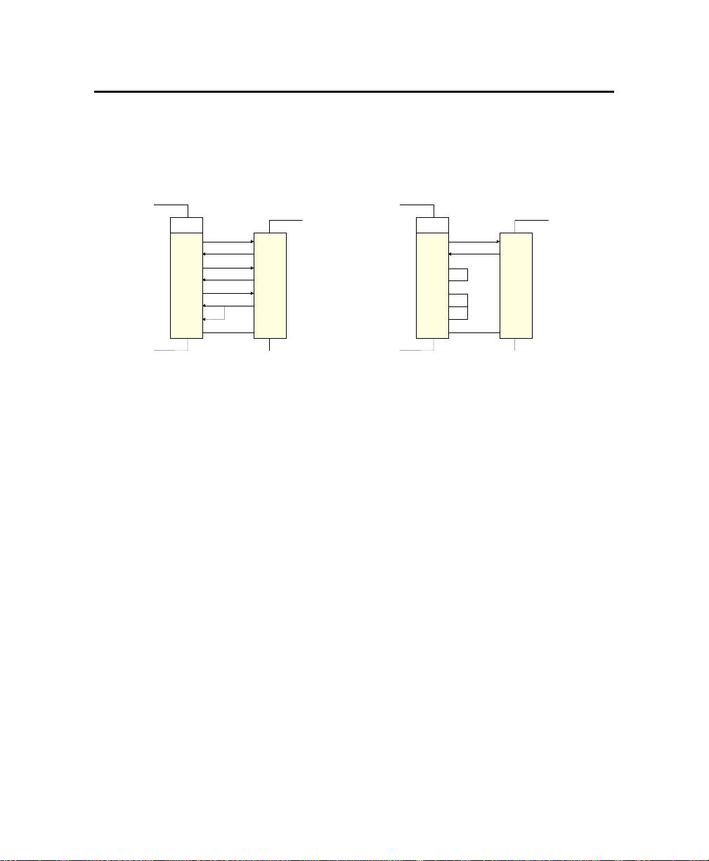
6. VT100 MODE
The VT100 mode may be required to communicate with the board using a remote terminal
through a serial communication link.
In this configuration, the remote terminal must emulate VT100 or ANSI terminal and support
an emulation program such as Telix or Procomm.
The serial cable must conform to one of the following:
COM
TXD
RXD
RTS
CTS
DSR
DCD
DTR
GND
Partial Setup
RXD
TXD
VT100 terminal
GND
TXD
DTR
RTS
CTS
Full Setup
RXD
TXD
DSR
DTR
CTS
RTS
GND
connector
TEK Board
VT100 terminal
connector
TEK Board
COM
RXD
DSR
DCD
GND
6.1. SETUP AND CONFIGURATION
Follow these steps for setting up VT100 Mode:
Power off your VIPer830 and install the jumper W5 to enable the VT100 Mode. Note:
both Serial Port 1 and Serial Port 2 su pport th e VT100 Mode.
Conne ct the serial cable. Note: if a full setup cable is not re quired, a partial cable with
only the TXD and RXD lines can be used. Simply loop back the control lines according
to the partial setup cable diagram.
Power on your VIPer830, run the BIOS Setup program, select the Integrated Peripherals
option, and choose a communication port.
The remote terminal must be set to support the following protocol:
8 Bits / No Parity / 1 stop bit / Echo Off.
6.2. RUNNING WITHOUT A TERMINAL
The board can boot up without a screen or terminal attached. However, if VT100 Mode is
desired, but the terminal is to be disconnected, you must ensure that the control lines are in an
active state. Failing this, the system ma y "hang" while waiting for the control lines to become
active. Wiring the cable according to the partial setup allows the lines to remain active. This
does not apply if the VT100 jumper is not set.
6-1
Page 61

APPENDICES
A
A. BOARD SPECIFICATIONS
B. MEMORY AND I/O MAPS
RT
3
P
C.
D. CONNECTOR PINOUTS
E.
F.
BOARD DIAGRAMS
BIOS SETUP ERROR CODES
EMERGENCY PROCEDURE
Page 62

A. BOARD SPECIFICATIONS
VIPer830 DESCRIPTION
Overview
Half-Size ISA Industrial Single Board Computer
Supported
Microprocessors
Data Path
Bus Interface
System Memory
Cache Memory
Boot Block Flash
I/Os
Intel Celeron at 300, 333, 366, 400, 433MHz and future speeds
440BX PCI chipset
64-bit on CPU and memory bus ; 32-bit on PCI bus ; 16-bit on ISA bus
66MHz Front Side Bus, SDRAM bus (100MHz future speed support)
PC/AT bus or stand-alone operation
PCI Rev 2.1 compliant ; external expansion through PC/104-Plus
connector
USB interface
EIDE interface
Up to 128MB of Synchronous DRAM or 256MB of Registered SDRAM
shared on one 168-pin DIMM socket.
1M64/72, 2M64/72, 4M64/72, 8M64/72,
Standard 3V single-sided or double-sided modules ; ECC supported
Level 1: 16/16KB Instruction/Data CPU-internal L1 cache
Level 2: 128KB pipelined burst L2 cache (on t he CPU module), ECC
protected. Same speed as the CPU core.
256KB of Flash BIOS for field upgrade
USB Two USB ports, software compatible with NS16C550
Serial Two UART serial ports configurable as COM1-4.
COM2 is configurable as RS-232, RS-422, or RS-485.
Parallel One bi-directional multimode port with EPP and ECP support
Hard Disk Enhanced IDE interface for up to two devices in
Master/Slave configuration; LBA, PIO Mode 0-4 and Ultra
DMA/33
Flash Disk Optional CompactFlash disk interface on the Secondary
EIDE channel, user upgradable, bootable
Floppy Supports for two disk drives from 360KB to 2.88MB
Ethernet Auto-select 10Base-T, 100Base-TX (Intel 82559)
Keyboard Standard AT and PS/2 keyboard
Mouse PS/2 mouse
A-1
Page 63

VIPer830 - Technical Reference Manual
VIPer830 DESCRIPTION
Video
Connectors
BIOS Features
Integrated AGP 64-bit video controller from Chips and Technologies
(69000) with 2MB of on-chip RSDRAM video memory
Simultaneous CRT / Flat Panel display support
CRT: up to 1024x768x64K colors or 1280x1024x256 colors
FP: 3.3V and 5V panels are s upported. Power is provided through
DS TN, TFT color displays ; Get Panel Type function
Supports up to 1280x1024x256 SXGA panels
Edge Bracket
CRT video 15-pin D-Sub
Ethernet RJ-45 with built-in LEDs
PS/2 mouse 6-pin Mini-DIN
PS/2 keyboard 6-pin Mini-DIN
Onboard Connectors
IDE Hard Drive 40-pin shrouded header
Floppy Disk 34-pin shrouded header
Kbd, Spk, LED 16-pin shrouded header
USB 10-pin connector
Flat Panel 50-pin + 20-pin shrouded headers
Fan 2-pin lock header
Power 6-pin connector
PS/2 Mouse 4-pin lock header
CompactFlash 40-pin dedicated connector
Parallel Port 26-pin shrouded header
Serial Ports 10-pin shrouded headers
Power Down 2-pin lock header
PC/104+ PC/104+ standard connector
Award BIOS in Boot Block Flash.
Batteryless operation with CMOS copy in the flash BIOS device
Auto configuration, extended setup, PnP support.
Extension for Diskless, keyboardless, and videoless operations.
BIOS POST and Setup console redirection to serial port.
Boot Block Flash with emergency recovery code.
System and video, BIOS shadowing
Advanced thermal management with CPU resume and overheat alarm.
Ability to support MS-DOS and other applications from Flash disk.
Y2K compliant.
the flat panel cable.
A-2
Page 64
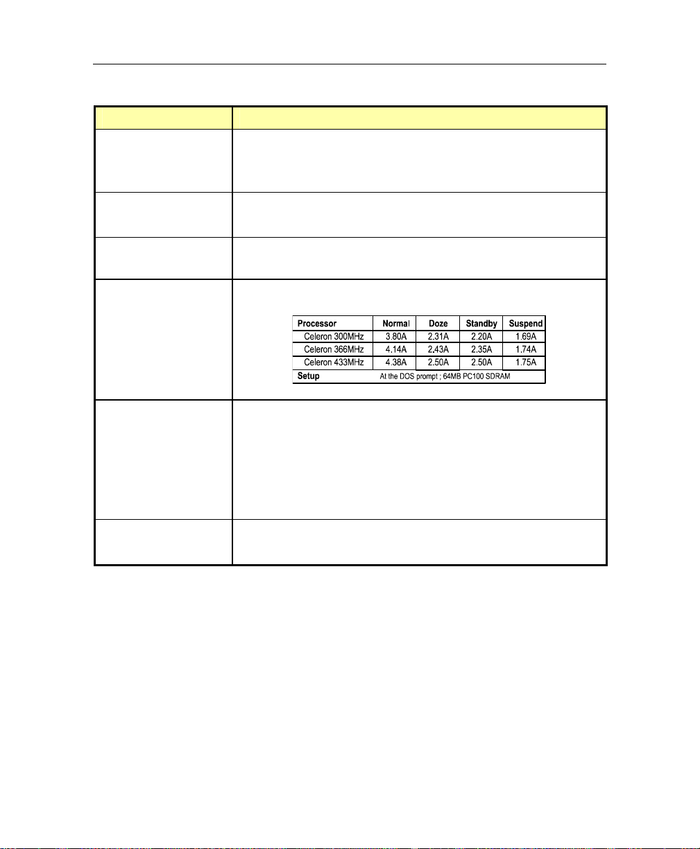
VIPer830 DESCRIPTION
Supervisory
Operating System
Compatibility
Dimensions
Power Requirements
Board Specifications
Two-stage digital watchdog timer ;
CPU temperature monitoring ; Power failure / low battery detector;
Built-in Ethernet activity / link.LEDs
MS-DOS
Windows
®
6.2x, Windows® 3.11, Windows® 95, Windows® 95 OSR2,
®
NT 4.0, Windows® NT 5.0, Windows® 98, QNX 4.24, etc
7.125 x 4.80 inches / 181 x 122 mm
Half-size form factor
Supply Voltages +5V, ±5%
Reliability
Environmental
Conditions
MTBF: over 100,000 hours (MIL-HDBK-217F)
Designed to meet or exceed:
Safety: UL1950 ; CSA C22.2 No950 ; EN 60950 ; IEC950
EMI/EMC: FCC 47 CFR Part 15/CISPR22 ;
CE Mark to EN55022/EN50082.
USB and keyboard/mouse voltage protected by self-resetting fuses.
Board serial nu mber in EEPROM
Operating Temp. 0 to +60°C (with airflow) - 5% to 95%
Storage Temp. -30°C to +85°C
A-3
Page 65
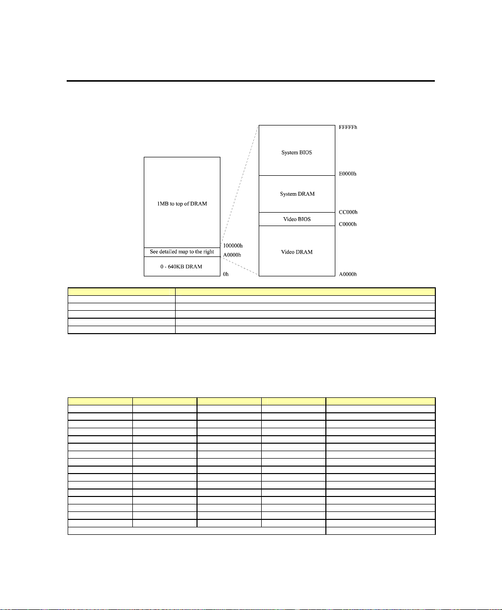
B. MEMORY & I/O MAPS
B.1. MEMORY MAPPING
Address Function
00000-9FFFF 0-640 KB DRAM
A0000-BFFFF 128KB Video Memory
C0000-CBFFF 48KB Video BIOS
E0000-FFFFF 128KB Main BIOS
100000-Top of DRAM 1 MB - Top of DRAM
Please note that if the Boot from LAN option is activated, the BIOS LAN (30KB) is
located between CC000h and E0000h.
B.2. I/O MAPPING
Address Optional Add. Optional Add. Optional Add. Function
000-01F DMA Controller 1
020-03F Interrupt Controller 1
040-05F Timers
060-06F Keyboard
070-07F Real-time clock
080-09F DMA Page Register
0A0-0BF Interrupt Controller 2
0C0-0DF DMA Controller 2
0F0-0F1, 0F8-0FF Math Coprocessor
190-197 290-297 390-397 Control Port
1F0-1F7, 3F6 Primary IDE
170-177, 376 Secondary IDE
3F0-3F7 370-377 Floppy Disk
378-37A 3BC-3BE 278-27A Parallel Port (LPT1 by default)
3F8-3FF (COM1) 2F8-2FF (COM2) 3E8-3EF (COM3) 2E8-2EF (COM4) Serial Port 1 (COM1 by default)
2F8-2FF (COM2) 3F8-3FF (COM1) 3E8-3EF (COM3) 2E8-2EF (COM4) Serial Port 2 (COM2 by default)
3C0-3CF, 3D0-3DF, 3B0-3BB Graphics Controller (I2C Port)
B-1
Page 66

VIPer830 - Technical Reference Manual
B.3. IRQ LINES
The board is fully PC compatible with interrupt steering for PCI plug and play
Controller # 1 Controller # 2
IRQ 0 Timer Output 0 IRQ 8 Real-Time Clock
IRQ 1 Keyboard (Output Buffer Full) IRQ 9 Avai l able 1
IRQ 2 Cascade Controller # 2 IRQ 10 Available 1
IRQ 3 Serial Port 2 * IRQ 11 Available 1
IRQ 4 Serial Port 1 * IRQ 12 PS/2 Mouse
IRQ 5 Parallel Port 2 * IRQ 13 Coprocessor Error
IRQ 6 Floppy Controller * IRQ 14 Primary IDE * or available 1
IRQ 7 Parall el Port 1 * or Available 1IRQ 15 Secondary IDE * or available 1
* All functions marked with an asterisk (*) can be disabled or reconfigured.
1
Available lines service on board and external PCI/ISA PnP devices or a Legacy ISA device.
compatibility.
B.4. DMA CHANNELS
The board provides the functionality of two 8237 DMA controllers. Eight DMA channels
are available.
According to Plug and Play standards, the system BIOS automatically allocates DMA
Channel 1 or 3 for the parallel port's ECP mode. Channel 2 is reserved for the floppy
controller and Channel 4 is used to cascade Channels 0 through 7 to the microprocessor.
DMA Channel Function
DMA 0 Available
DMA 1 PnP available (ECP)
DMA 2 Floppy controller
DMA 3 PnP available (ECP) *
DMA 4 Cascade cont rol l e r # 1
DMA 5 PnP available
DMA 6 PnP available
DMA 7 PnP available
B-2
Page 67
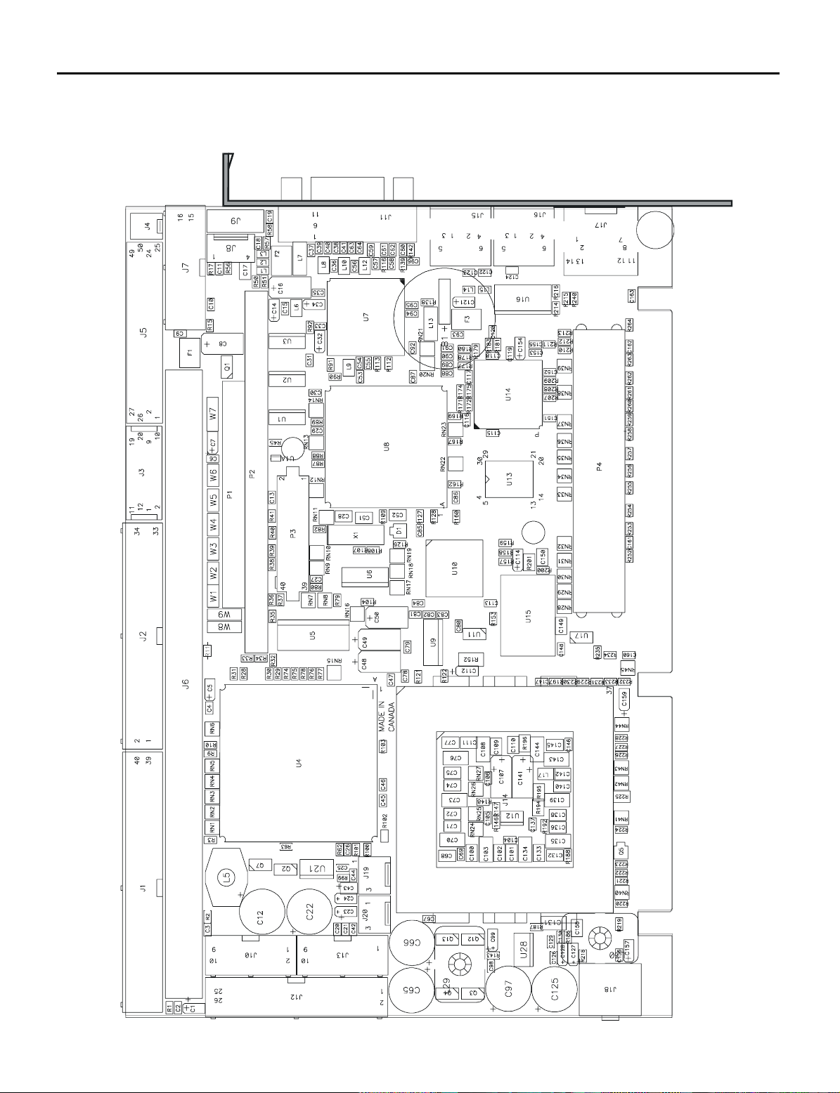
C. BOARD DIAGRAMS
C.1. ASSEMBLY - TOP DIAGRAM
C-1
Page 68
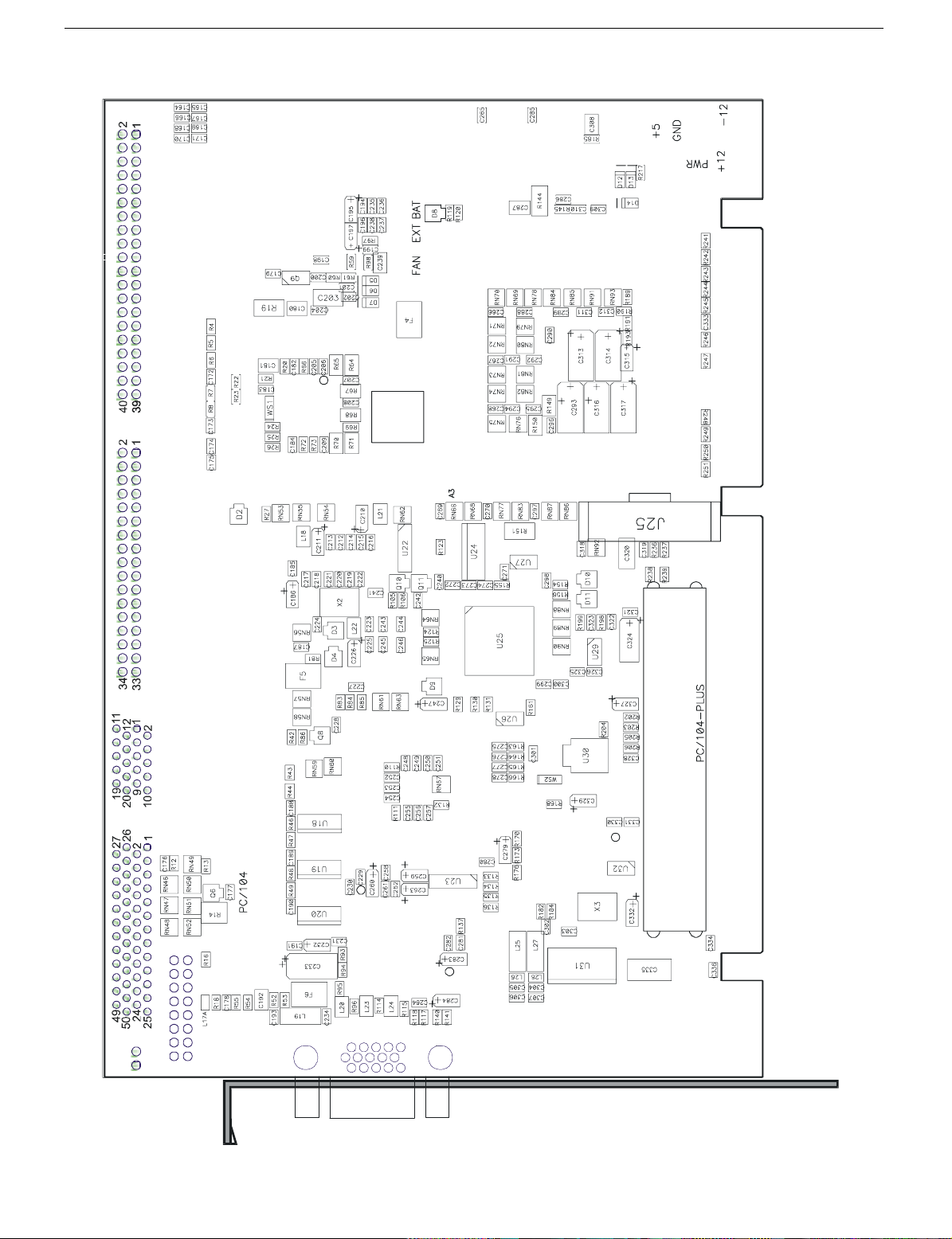
VIPer830 - Technical Reference Manual
C.2. ASSEMBLY - BOTTOM DIAGRAM
C-2
Page 69
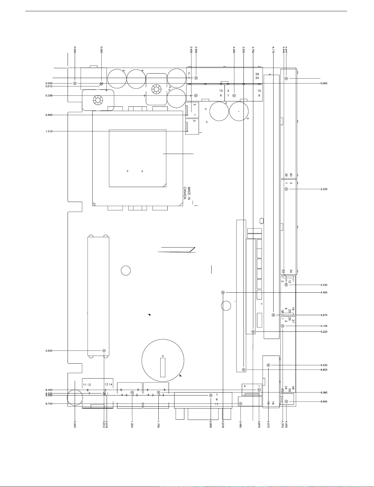
C.3. ASSEMBLY - MECHANICAL DIAGRAM
Board Diagrams
-0.150
-0.325
-0.112
CPU SOCKET 0.250”
CPU HEIGHT 0.131”
FAN HEIGHT 1.00”
-0.100
C-3
3.750
Page 70

D. CONNECTOR PINOUTS
Connectors and headers are listed below:
J1
J2
J3
J4
J5
J7
J8
J9
J10
J11
J12
J13
J15
J16
J17
J18
J19
J20
P1/P2
P3
P4
IDE Hard Disk Drive connector
Floppy Disk connector
Flat Panel Connector
Power Button header
Flat Panel Connector
Keyboard / Speaker
PS/2 Mouse header
Dual USB header
Serial Port 1 header
SVGA CRT Video connector
Parallel Port header
Serial Port 2 header
PS/2 Mouse mini-DIN connector
PS/2 Keyboard mini-DIN connector
Ethernet connector
External Power connector
Fan Power header
External Battery header
PC/104 connector (16-bit/8-bit)
CompactFlash connector
PC/104+ connector
D-1
Page 71
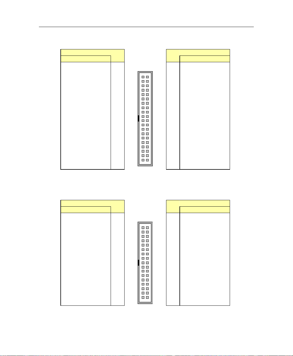
VIPer830 - Technical Reference Manual
D.1. IDE H ARD DISK DRIVE CONNECTOR (J1)
Pin Number
Signal Signal
RST#
D7
D6
D5
D4
D3
D2
D1
D0
GND
REQ
IOW#
IOR#
IORDY
DACK#
IRQ
A1
A0
CS0#
ACT#
1
3
5
7
9
11
13
15
17
19
21
23
25
27
29
31
33
35
37
39
Top View
1392
40
Pin Number
2
GND
4
D8
6
D9
8
10
12
14
16
18
20
22
24
26
28
30
32
34
36
38
40
D10
D11
D12
D13
D14
D15
N.C.
GND
GND
GND
CSEL
GND
N.C.
DIAG#
A2
CS1#
GND
D.2. FLOPPY DISK DRIVE CONNECTOR (J2)
Pin Number
Signal
GND
GND
GND
GND
GND
GND
GND
GND
N.C.
GND
GND
GND
GND
N.C.
FDETECT#
GND
N.C.
1
3
5
7
9
11
13
15
17
19
21
23
25
27
29
31
33
Top View
1352
36
Pin Number
Signal
2
DENSEL#
4
N.C.
6
N.C.
8
10
12
14
16
18
20
22
24
26
28
30
32
34
INDEX#
MTR0#
DSEL1#
DSEL0#
MTR1#
DIR#
STEP#
WDATA#
WGATE#
TRK0#
WRPROT#
RDATA#
HDSEL#
DSKCHG#
D-2
Page 72
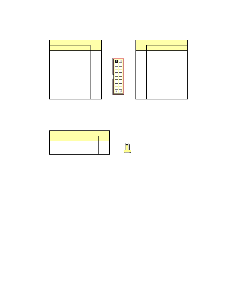
D.3. FLAT PANEL (J3)
Pin Number
Signal
FP24
FP25
FP26
FP27
GND
FP28
FP29
FP30
FP31
GND
1
2
3
4
5
6
7
8
9
10
D.4. PO WER BUTTON (J4)
Pin Number
Signal
PWR_BTN
GND
1
2
Top View
Front View
1
Connector Pinouts
Pin Number
Signal
11
12
13
14
15
16
17
18
19
20
FP32
FP33
FP34
FP35
GND
SHFCLK#
GP1
GP2
ACTI
FPVAR
D-3
Page 73
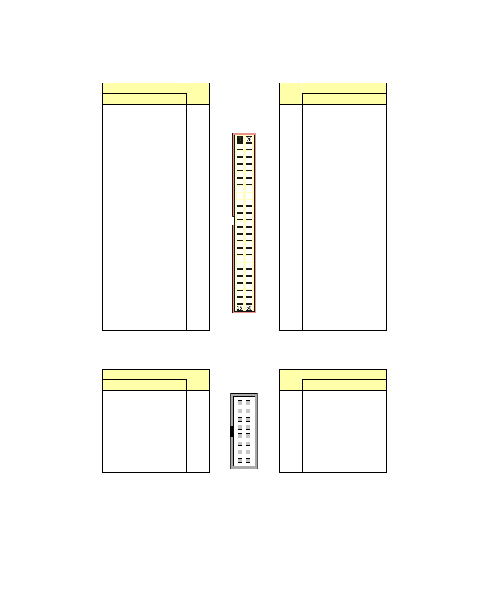
VIPer830 - Technical Reference Manual
D.5. FLAT P ANEL CONNECTOR (J 5)
Pin Number
Signal
ENAVCC
FPVAR
ENVEE
STDBY#
ENABLK
GND
M/DE
FPVAR
GND
LP/DE
FLM
GND
SHFCLK
GND
FP0
FP1
GND
FP2
FP3
GND
FP4
FP5
GND
FP6
FP7
1
2
3
4
5
6
7
8
9
10
11
12
13
14
15
16
17
18
19
20
21
22
23
24
25
Top View
Pin Number
Signal
26
27
28
29
30
31
32
33
34
35
36
37
38
39
40
41
42
43
44
45
46
47
48
49
50
GND
FP8
FP9
GND
FP10
FP11
GND
FP12
FP13
GND
FP14
FP15
GND
FP16
FP17
GND
FP18
FP19
GND
FP20
FP21
GND
FP22
FP23
GND
D.6. KEYBOARD/SPEAKER CONNECTOR (J7)
Pin Number
Signal
KB:CLK
KB:DATA
VCC
SPEAKER
N.C.
DOWNLD#
PBRES#
IDE:ACT#
1
3
5
7
9
11
13
15
Top View
1152
16
Pin Number
Signal
2
GND
4
GND
6
VCC
8
VCC
10
12
14
16
GND
GND
GND
VCC
D-4
Page 74
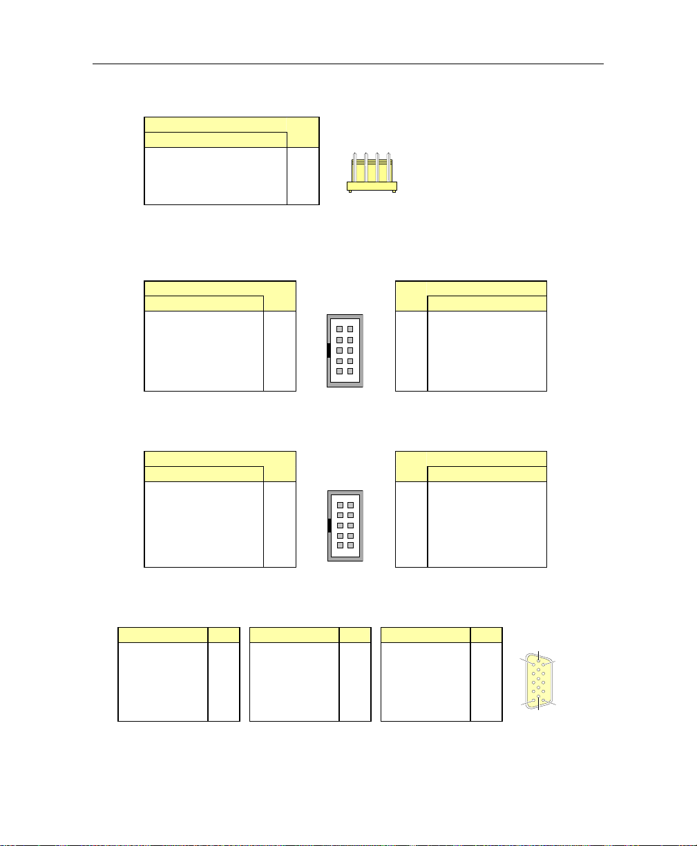
D.7. PS/2 MOUSE HEADER (J8)
5
Pin Number
Signal
MOUSE:CLOCK
GND
MOUSE:DATA
VCC
1
2
3
4
Front View
1
D.8. DUAL USB CONNECTOR (J9)
Pin Number
Signal
USB0:VCC
USB0:DATA-
USB0:DATA+
USB0:GND
GND
1
3
5
7
9
Top View
192
10
Pin Number
Signal
2
4
6
8
10
D.9. SERIAL PORT 1 CONNECTOR (J10)
Pin Number
Signal
DCD
RXD
TXD
DTR
GND
1
3
5
7
9
Top View
192
10
Pin Number
Signal
2
4
6
8
10
D.10. VIDEO CONNECTOR (J11)
Signal Signal Signal
RED
GREEN
BLUE
N.C.
GND
1
Analog GND
2
3
Analog GND
Analog GND
4
5
N.C.
GND
6
7
8
9
10
USB1:VCC
USB1:DATAUSB1:DATA+
USB1:GND
GND
DSR
RTS
CTS
RI
N.C.
N.C.
SDATA
HSYNC
VSYNC
SCLK
11
12
13
14
15
Connector Pinouts
Top View
6
111
111
15
10
D-5
Page 75
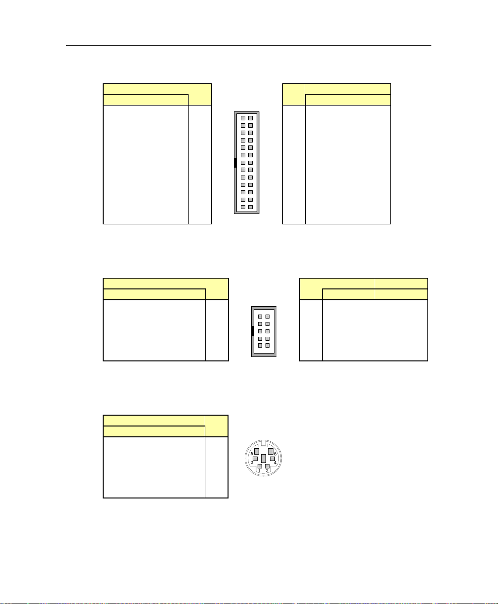
VIPer830 - Technical Reference Manual
D.11. PARALLEL PORT CONNECTOR (J12)
Pin Number
Signal
STB#
D0
D1
D2
D3
D4
D5
D6
D7
ACK#
BUSY
PE
SLCT
1
3
5
7
9
11
13
15
17
19
21
23
25
Top View
1252
26
Pin Number
Signal
2
ALF#
4
ERR#
6
INIT#
8
10
12
14
16
18
20
22
24
26
SLCTIN#
GND
GND
GND
GND
GND
GND
GND
GND
GND
D.12. SERIAL PORT 2 CONNECTOR – RS-232/RS-422 (J13)
Pin Number
Signal
(RS-422)
RSV
RX (-)
TX (-)
RSV
GND
(RS-232)
DCD
RXD
TXD
DTR
GND
1
3
5
7
9
Top View
192
10
Pin Number
Signal
(RS-232)
2
DSR
4
RTS
6
CTS
8
10
RI
N.C.
(RS-422)
RSV
RX (+)
TX (+)
RSV
N.C.
D.13. PS/2 MOUSE CONNECTOR (J15)
Pin Number
Signal
MOUSE:DATA
N.C.
GND
VCC
MOUSE:CLK
N.C.
1
2
3
4
5
6
Front View
D-6
Page 76
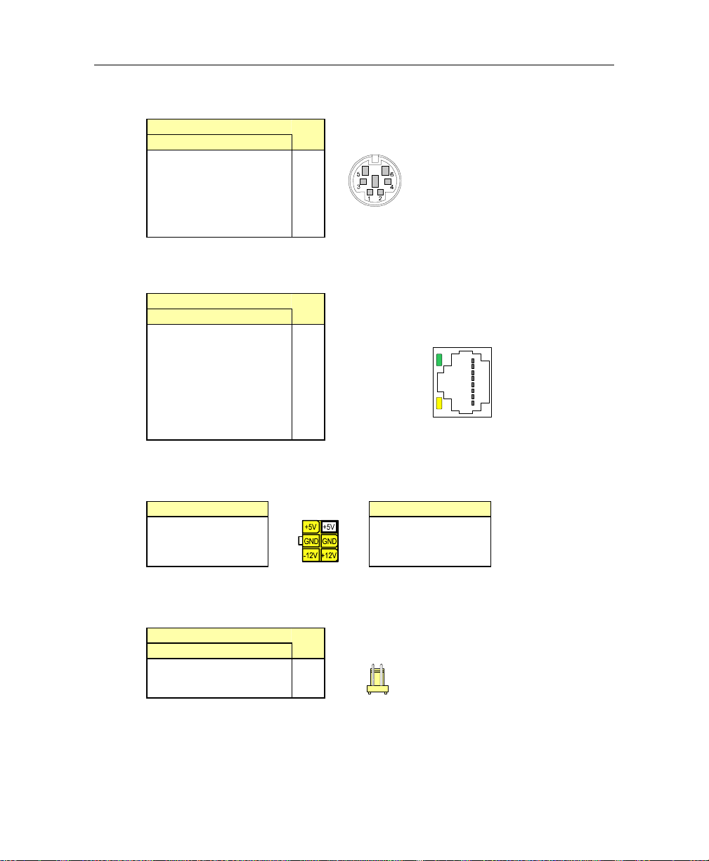
D.14. PS/2 KEYBOARD CONNECTOR (J16)
G
Y
Pin Number
Signal
KB:DATA
N.C.
GND
VCC
KB:CLK
N.C.
1
2
3
4
5
6
Front View
D.15. ETHERNET CONNECTOR (J17)
Pin Number
Signal
TX+
TXRX+
N.C.
N.C.
RXN.C.
N.C.
1
2
3
4
5
6
7
8
Top View
reen
ellow
D.16. EXTERNAL POWER CONNECTOR (J18)
Signal
VCC
GND
-12V
Top View
Signal
VCC
GND
+12V
D.17. FAN HEADER (J19)
Pin Number
Signal
VCC
GND
1
2
Front View
1
Connector Pinouts
1
8
D-7
Page 77
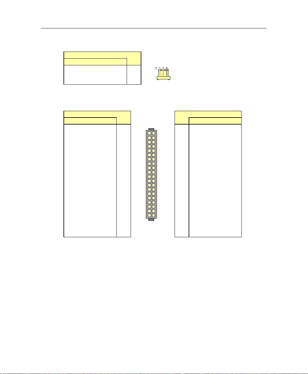
VIPer830 - Technical Reference Manual
D.18. EXTERNAL BATTERY HEADER (J20)
Pin Number
Signal
EXT_BATT
GND
EXT_BATT
1
2
3
Front View
D.19. IDE COMPACTFLASH CONNECTOR (P3)
Pin Number
Signal Signal
D11
D12
D13
D14
D15
CS1#
DMACK#
DMARQ
PDIAG#
IRQ15
VCC
GND
RESET#
CSEL
A1
A0
D0
D1
D2
IOCS16#
1
3
5
7
9
11
13
15
17
19
21
23
25
27
29
31
33
35
37
39
Top View
1
39
Pin Number
2
40
2
4
6
8
10
12
14
16
18
20
22
24
26
28
30
32
34
36
38
40
GND
D3
D4
D5
D6
D7
CS0#
IOR#
IOW#
VCC
VCC
GND
GND
A2
DASP#
IORDY
D8
D9
D10
GND
D-8
Page 78
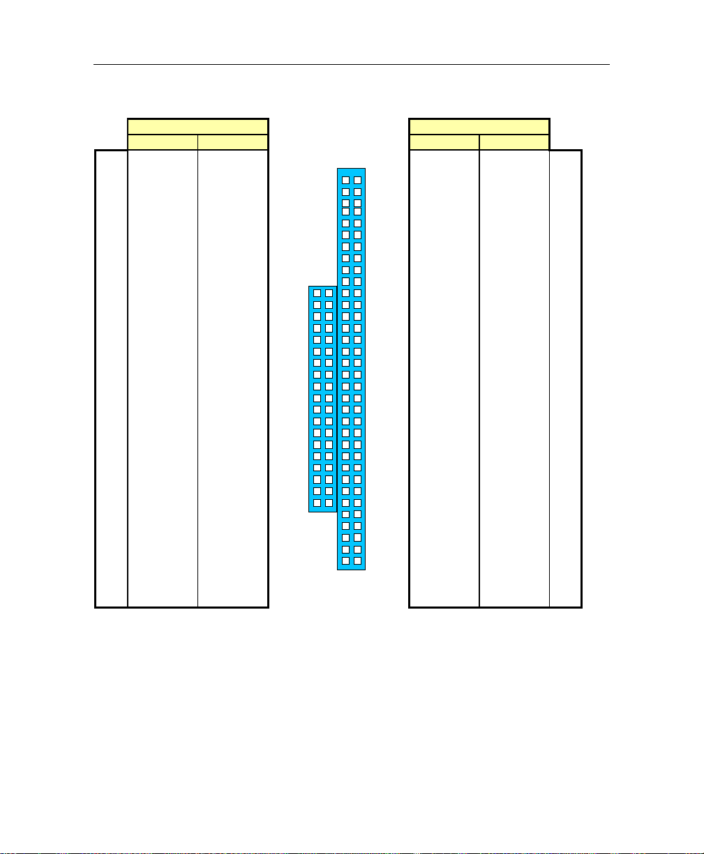
Connector Pinouts
D.20. PC/104 CONNECTORS (P1/ P2)
P1 P2
D C A B
IOCHK#
SD7
SD6
SD5
SD4
SD3
SD2
SD1
SD0
IOCHRDY
AEN
SA19
SA18
SA17
SA16
SA15
SA14
SA13
SA12
SA11
SA10
SA9
SA8
SA7
SA6
SA5
SA4
SA3
SA2
SA1
SA0
GND
GND
ESET DRV
R
VCC
IRQ9
-5V
DRQ2
-12V
0WS#
+12V
GND
SMEMW#
SMEMR#
IOW#
IOR#
DACK3#
DRQ3
DACK1#
DRQ1
EFRESH#
R
SYSCLK
IRQ7
IRQ6
IRQ5
IRQ4
IRQ3
DACK2#
T/C
BALE
VCC
OSC
GND
GND
0
1
2
3
4
5
6
7
8
9
10
11
12
13
14
15
16
17
18
19
GND
MEMCS16#
IOCS16#
IRQ10
IRQ11
IRQ12
IRQ15
IRQ14
DACK0#
DRQ0
DACK5#
DRQ5
DACK6#
DRQ6
DACK7#
DRQ7
VCC
MASTER#
GND
N.C.
GND
SBHE#
LA23
LA22
LA21
LA20
LA19
LA18
LA17
MEMR#
MEMW#
SD8
SD9
SD10
SD11
SD12
SD13
SD14
SD15
GND
A
B
D
C
P1 P2
1
2
3
4
5
6
7
8
9
10
11
12
13
14
15
16
17
18
19
20
21
22
23
24
25
26
27
28
29
30
31
32
D-9
Page 79
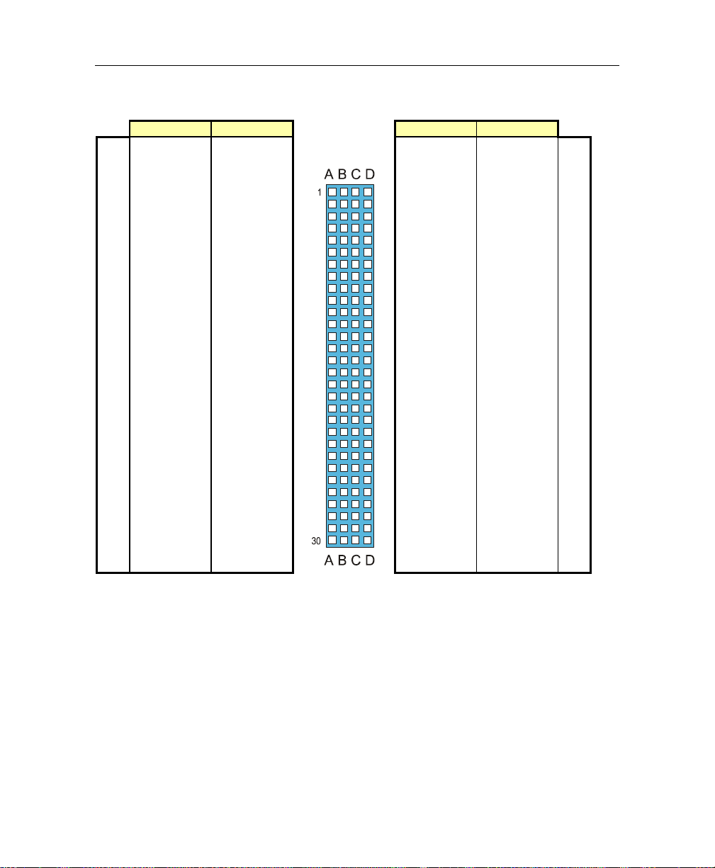
VIPer830 - Technical Reference Manual
D.21. PC/104-PLUS CONNECTOR (P4)
A B C D
1
5V_KEY
2
VI/O (5V)
3
4
5
6
7
8
9
10
11
12
13
14
15
16
17
18
19
20
21
22
23
24
25
26
27
28
29
30
# Active Low Signal
AD05
C/BE0#
GND
AD11
AD14
+3.3V
SERR#
GND
STOP#
+3.3V
FRAME
GND
AD18
AD21
+3.3V
IDSEL0
AD24
GND
AD29
VCC
REQ0#
GND
GNT1#
VCC
CLK
GND
+12V
-12V
N.C.
AD02
GND
AD07
AD09
VCC
AD13
C/BE1#
GND
PERR#
+3.3V
TRDY#
GND
AD16
+3.3V
AD20
AD23
GND
C/BE3#
AD26
VCC
AD30
GND
REQ2#
VCC
CLK0
VCC
INTD#
INTA#
N.C.
VCC
AD01
AD04
GND
AD08
AD10
GND
AD15
SB0#
+3.3V
LOCK#
GND
IRDY#
+3.3V
AD17
GND
AD22
IDSEL1
VCC
AD25
AD28
GND
REQ1#
VCC
GNT2#
GND
CLK3
VCC
INTB#
N.C.
AD00
VCC
AD03
AD06
GND
N.C.
AD12
+3.3V
PAR
SDONE
GND
DEVSEL#
+3.36V
C/BE2#
GND
AD19
+3.3V
IDSEL2
IDSEL3
GND
AD27
AD31
VCC
GNT0#
GND
CLK1
GND
RST#
INTC#
GND
1
2
3
4
5
6
7
8
9
10
11
12
13
14
15
16
17
18
19
20
21
22
23
24
25
26
27
28
29
30
D-10
Page 80

E. BIOS SETUP ERROR CODES
E.1. POST BEEP
POST beep codes are defined in the BIOS to provide low level tone indication when an
error occurs during the BIOS initialization.
Beep codes consist of a combination of long and short beeps. They are
described as follows:
Beep Codes
Post code Beep Code Description
41 **-* Entering the boot block recovery code (i.e. Main BIOS
checksum error)
22 *-*-* Error when getting the boot block flash ID code
33 *-*-*-* Error when erasing the boot block flash
44 *-*-*-*-* E rror when programming the boot block flash
55 *-* S uccess of the boot block recovery code. The board is ready
to be manually reset.
LEGEND
Symbol Description
* 1 Beep code
- Silence
E.2. POST MESSAGES
During the Power On Self Test (POST), if the BIOS detects an error requiring you to do
something to fix, it will either sound a beep code or display a message.
If a message is displayed, it will be accompanied by:
“PRESS F1 TO CONTINUE, DEL TO ENTER SETUP”.
E-1
Page 81

VIPer830 - Technical Reference Manual
E.3. ERROR MESSAGES
One or more of the following messages may be displayed if the BIOS detects an error
during the POST. This list includes messages for both the ISA and EISA BIOS.
CMOS BATTERY HAS FAILED
CMOS battery is no longer functional. It should be replaced.
CMOS CHECKSUM ERROR
Checksum of CMOS is incorrect. This can indicates that CMOS has become corrupt.
This error may have been caused by a weak battery. Check the battery and replace if
necessary.
DISK BOOT FAILURE, INSERT SYSTEM DISK AND PRESS ENTER
No boot device was found. This could mean either a boot drive was not detected or the
drive does not contain proper system boot files. Insert a system disk into Drive A and
press Enter. If you assumed the system would boot from the hard drive, make sure the
hard drive is installed correctly and all cables are properly attached. Also be sure the
disk is formatted as a boot device. Then reboot the system.
DISKETTE DRIVES OR TYPES MISMATCH ERROR - RUN SETUP
Type of diskette drive installed in the system is different from CMOS de finition. Run
Setup to reconfigure the drive type correctly.
DISPLAY SWITCH IS SET INCORRECTLY
Display switch on the motherboard can be set to either monochrome or color. This
indicates the switch is set to a different setting than indicated in Setup. Determine
which setting is correct, and then either turn off the system and change the jumper, or
enter Setup and change the VIDEO selection.
DISPLAY TYPE HAS CHANGED SINCE LAST BOOT
Since last powering off the system, the display adapter has been changed. You must
configure the system for the new display type.
E-2
Page 82

BIOS Setup Error Codes
ERROR ENCOUNTERED INITIALIZING HARD DRIVE
Hard drive cannot be initialized. Be sure the adapter is installed correctly and all cables
are correctly and firmly attached. Also be sure the correct hard drive type is selected in
Setup.
ERROR INITIALIZING HARD DRIVE DISK CONTROLLER
Cannot initialize controller. Make sure the cable is correctly connected. Be sure the
correct hard drive type is selected in Setup. Also check to see if any jumper needs to
be set correctly on the hard drive.
FLOPPY DISK CNTRLR ERROR OR NO CNTRLR PRESENT
Cannot find or initialize the floppy drive controller. Make sure the floppy disk is
correctly connected. If there are no floppy drives installed, be sure the Disk Drive
selection in Setup is set to NONE.
KEYBOARD ERROR OR NO KEYBOARD PRESENT
Cannot initialize the keyboard. Make sure the keyboard is attached correctly and no
keys are being pressed during the boot.
If you are purposely configuring the system without a keyboard, set the error halt
condition in Setup to HALT ON ALL, BUT KEYBOARD. This will cause BIOS to
ignore the missing keyboard and continue the boot.
MEMORY ADDRESS ERROR AT ...
Indicates a memory address error at a specific location. You can use this location along
with the memory map for your system to find and replace the bad memory chips.
MEMORY PARITY ERROR AT ...
Indicates a memory parity error at a specific location. This location can be used to
locate a bad memory module.
MEMORY SIZE HAS CHANGED SINCE LAST BOOT
Memory has been added or removed since the last boot.
E-3
Page 83

VIPer830 - Technical Reference Manual
MEMORY VERIFY ERROR AT ...
Indicates an error during the memory verification.
OFFENDING SEGMENT
This message is used in conjunction with the I/O CHANNEL CHECK and RAM
PARITY ERROR messages when the segment that has caused the problem cannot be
isolated.
PRESS A KEY TO REBOOT
This will be displayed on the screen when an error occurs that requires you to reboot.
Press any key and the system will reboot.
PRESS F1 TO DISABLE NMI, F2 TO REBOOT
When BIOS detects a Non-maskable Interrupt condition during boot, this will allow
you to disable the NMI and continue to boot, or you can reboot the system with the
NMI enabled.
RAM PARITY ERROR - CHECKING FOR SEGMENT ...
Indicates a parity error in Random Access Memory.
E-4
Page 84

BIOS Setup Error Codes
E.4. POST CODES
✎ NOTE
ISA POST codes are output to port address 80h.
POST Codes
POST
(hex)
C0 Turn Off Chipset Cache OEM Specific-Cache control
01 Processor Test 1 Processor Status (1FLAGS) Verification.
02 Processor Test 2 Read/Write/Verify all CPU registers except SS, SP, and BP with data
03 Initialize Chips Disable NMI, PIE, AIE, UEI, SQWV.
04 Test Memory Refresh Toggle RAM must be periodically refreshed in order to keep the memory from
05 Blank video,
Initialize keyboard
06 Reserved
07 Test CMOS Interface and
Battery Status
BE Chipset Default Initialization Program chipset registers with power on BIOS defaults.
C1 Memory presence test OEM Specific-Test to size on-board memory.
C5 Early Shadow OEM Specific-Early Shadow enable for fast boot.
C6 Cache presence test External cache size detection.
08 Setup low memory Early chip set initialization.
09 Early Cache Initialization Cyrix CPU initialization.
0A Setup Interrupt
Vector Table
0B Test CMOS RAM Checksum Test CMOS RAM Checksum, if bad, or insert key pressed, load
0C Initialize keyboard Detect type of keyboard controller (optional).
Name Description
Tests the following processor status flags: Carry, zero, sign, overflow.
The BIOS will set each of these flags, verify they are set, then turn
each flag off and verify it is off.
pattern FF and 00.
Disable video, parity checking, DMA.
Reset math coprocessor.
Clear all page registers, CMOS shutdown byte.
Initialize timer 0, 1, and 2, including set EISA timer to a known state.
Initialize DMA controllers 0 and 1.
Initialize interrupt controllers 0 and 1.
Initialize EISA extended re giste rs.
decaying. This function assures that the memory refresh function is
working properly.
Keyboard controller initialization.
Verifies CMOS is working correctly, detects bad battery.
Memory presence test.
OEM chip set routines.
Clear low 64K of memory.
Test first 64K memory.
Cache initialization.
Initialize first 120 interrupt vectors with SPURIOUS_INT_HDLR and
initialize INT 00h-1Fh according to INT_TBL.
defaults.
Set NUM LOCK status.
...
E-5
Page 85

VIPer830 - Technical Reference Manual
0D Initialize Video Interface Detect CPU clock.
0E Test Video Memory Test video memory, write sign-on message to screen.
0F Test DMA Controller 0 BIOS checksum test.
10 Test DMA Controller 1
11 Test DMA Page Registers Test DMA Page Registers.
12-13 Reserved
14 Test Timer Counter 2 Test 8254 Timer 0 Counter 2.
15 Test 8259-1 Mask Bits Verify 8259 Channel 1 masked interrupts by alternately turning off and
16 Test 8259-2 Mask Bits Verify 8259 Channel 2 masked interrupts by alternately turning off and
17 Test Stuck 8259’s Interrupts Bits Turn off interrupts then verify no interrupt mask register is on.
18 Test 8259 Interrupt Functionality Force an interrupt and verify the interrupt occurred.
19 Test Stuck NMI Bits (Parity/IO
Check)
1A Display CPU clock
1B-1F Reserved
20 Enable Slot 0 Initialize slot 0 (System Board).
21-2F Enable Slots 1-15 Initialize slots 1 through 15.
30 Size Base and Extended
Memory
31 Test Base and Extended
Memory
32-3B Reserved
3C Setup Enabled
3D Initialize & Install Mouse Detect if mouse is present, initialize mouse, install interrupt vectors.
3E Setup Cache Controller Initialize Cache controller.
3F Reserved
BF Chipset Initialization Program chipset registers with Setup values.
40 Display virus protect disable or enabl e
41 Initialize Floppy Drive &
Controller
42 Initialize Hard Drive & Controller Initialize hard drive controller and any drives.
43 Detect & Initialize Serial/Parallel
Ports
44 Reserved
45 Detect & Initialize Math
Coprocessor
46-4D Reserved
4E Manufacturing POST Loop or
Display Messages
Read CMOS location 14h to find out type of video in use.
Detect and Initialize Video Adapter.
Setup shadow RAM - Enable shadow according to Setup.
Keyboard detect and initialization.
on the interrupt lines.
on the interrupt lines.
Verify NMI can be cleared.
Size base memory from 256KB to 640KB and extended memory above
1 MB.
Test base memory from 256KB to 640KB and extended memory above
1 MB using various patterns.
NOTE: This will be skipped in ISA mode and can be « skipped » with
ESC key in EISA mode.
Initialize floppy disk drive controller and any drives.
Initialize any serial and parallel ports (also game port).
Initialize math coprocessor
Reboot if Manufacturing POST Loop pin is set.
Otherwise display any messages (i.e., any non-fatal errors that were
detected during POST) and enter Setup.
...
E-6
Page 86

BIOS Setup Error Codes
4F Security Check Ask password security (optional).
50 Write CMOS Write all CMOS values back to RAM and clear screen.
51 Pre-boot Enable Enable parity checker.
52 Initialize Option ROMs Initialize any option ROMs present from C8000h to EFFFFh.
53 Initialze Time Value Initialize time value in 40h: BIOS area.
60 Setup Virus Protect Setup virus protect according to Setup.
61 Set Boot Speed Set system speed for boot.
62 Setup NumLock Setup NumLock status according to Setup.
63 Boot Attempt Set low stack.
B0 Spurious If interrupt occurs in protected mode.
B1 Unclaimed NMI If unmasked NMI occurs, display:
E1-EF Setup Pages E1 - Page 1, E2 - Page 2, etc.
FF Boot
Enable NMI, Enable Cache before boot.
Note: When FSCAN option is enabled, will initialze from C8000h to
F7FFFh.
Boot via INT 19h.
Press F1 to disable NMI, F2 reboot.
E-7
Page 87

F. EMERGENCY PROCEDURE
Follow this procedure only in case of emergency such as a critical error
occurred during the Boot Block Flash BIOS update (when using UBIOS utility
program or saving the AWARD parameters into the flash memory) or if you meet
1. No POST code on a power up (when using a POST card).
2. System stops at POST 41(when using a POST card) and associated beep code is
generated (Refer to Section E.1).
3. Board does not boot, even after following all the usual verifications: cables, power,
bootup diskette.
F.1. EMERGENCY PROCEDURE
The Emergency Procedure is described as follows:
1. Remove the battery jumper (see Section 2 - Jumper Settings) to reset the CMOS
values.
2. Disab le the Power Fail Monitoring function (W9 removed).
3. Ensure the Supervisor I/O base address is set to 190h (see BIOS Setup Program).
4. Connect a 1.44MB floppy drive (drive A) to the board, and insert the EMERGENCY
diskette in it.
5. Power on the board. (Note that no VGA is present during this procedure.)
6. The Boot Block Flash update will be completed when the POST code 55 is displayed
(when using a POST card) or the associated beep code sounds (see Section E-1).
7. After the procedure is successfully completed, power down the board, install the
battery and Power Fail Monitoring jumpers and power up the board. Be aware to
restore the I/O base address as it was previously
The Boot Block Flash BIOS should be correctly programmed and the system should
run properly.
one of the following symptoms at anytime:
✎ NOTE
The preparation of an Emergency Diskette is described in Section F.2 Generate an Emergency Floppy Diskette.
F-1
Page 88

VIPer 830 Technical Reference Manual
F.2. GENERATE AN EMERGENCY FLOPPY DISKETTE
Use a system that has a 1.44 Mbytes floppy drive A.
1. Insert the EMERGENCY diskette in drive A.
2. Copy the two files WDISK.COM and EMERDISK.TEK from drive A: to your hard
drive (those files are available in your diskette package).
3. Remove the EMERGENCY diskette and insert a DOS formatted floppy diskette in
drive A.
4. At the DOS prompt of your hard drive (same path of the two files WDISK.COM and
EMERDISK.TEK), type WDISK EMERDISK.TEK then press Enter.
5. The program may display one of the following messages:
“Emergency Code transferred”
The emergency diskette has been successfully created. Take the appropriate
actions and restart from the step 4) when you see the following messages.
“Write to disk failure!”
Verify if your floppy diskette is write-protected.
“The file to program in flash was not found”
Be sure that EMERDISK.TEK file is in your current path.
“Unable to read the binary file” or “Unable to close the
opened file”
Possible floppy diskette corruption or bad data transfer between floppy disk
and host system.
“Unable to allocate a memory block of 256 Kbytes”
Not enough memory to run the WDISK program.
F-2
Page 89

GETTING HELP
We take great pride in our customer's successes. We strongly believe in provi ding full su pport
at all stages of your product development.
If at any time you encounter difficulties with your application or with any of our products, or
if you simply need guidance on system setups and capabilities, you may contact our
Technical Support department at:
CANADIAN HEADQUARTERS
Tel.: (450) 437-5682
Fax: (450) 437-8053
If you have any questions about our products or services, you may reach us at the above
numbers or by writing to:
616 Cure Boivin
Boisbriand, Quebec
J7G 2A7 CANADA
LIMITED WARRANTY
We ("the seller") warrant our boards to be free from defects in material and workmanship
for a period of two (2) years commencing on the date of shipment. The liability of the
seller shall be limited to replacing or repairing, at the seller's option, any defective units.
Equipment or parts which have been subject to abuse, misuse, accident, alteration, neglect,
or unauthor ized repair are not covered by this warr anty. This warranty is in li eu of all other
warranties expressed or implied.
Getting Help 1
Page 90

VIPer 830 Technical Reference Manual
Returning Defective Merchandise
If your product malfunctions, please do the following befo re returning any merchandise:
1) Call our Technical Support department in Canada at (450) 437-5682 or in Germany at
+49 811 / 600 15-0. Make certain you ha ve the follo wing at hand: t h e Invoice #, your
Purchase Order #, and the Serial Number of the defective board.
2) Give the serial number found on the back of the board and explain the nature of your
problem to a service technician.
3) If the problem cannot be solved over the telephone, the technician will further instruct
you on the return procedure.
4) Prior to returning any merchandise, make certain you receive an RMA # from our
Technical Support and clearly mark this number on the outside of the package you are
returning. To request a number, follow these steps: make a copy of the request form on
the following page, fill it out and fax it to us.
5) When returning goods, please include the name and telephone number of a person
whom we can contact for further explanations if necessary. Where applicable, always
include all duty papers and invoice( s) associated with the item(s) in question.
6) When returning a board:
i) Make certain that the board is properly packed: Place it in an antistatic plastic bag
and pack it in a rigid cardboard box.
ii) Ship prepaid to (but not insured):
Kontron Inc.
616 Cure Boivin
Boisbriand, Quebec
J7G 2A7 CANADA
Getting Help 2
Page 91
RETURN TO MANUFACTURER
AUTHORIZATION REQUEST
Contact Name : ______________________________________________________
Company name : ______________________________________________________
Street Address : ______________________________________________________
City : _________________ Province/State : _________________
Country : _________________ Postal/Zip Code : _________________
Phone Number : _________________ Extension : _________________
Fax Number : _________________
Serial Number Failure or Problem Description
P.O.#
(if not under
warranty)
Fax this form to our Technical department in Canada at (450) 437-8053
 Loading...