

Page 1

VIPer808
486/5x86 PROCESSOR
INDUSTRIAL SINGLE BOARD COMPUTER
TECHNICAL REFERENCE MANUAL
VERSION 1.2, MARCH 1997
TEKNOR INDUSTRIAL COMPUTERS INC.
616 Cure Boivin
Boisbriand, Quebec
J7G 2A7 CANADA
NOTE:
This manual is for reference purposes only.
Reproduction in whole or in part is authorized
provided TEKNOR INDUSTRIAL COMPUTERS INC.
is cited as the original source.
ref: M808S_1-2
Page 2

FOREWORD
The information in this document is provided for reference purposes only. TEKNOR does
not assume any liability for the application of information or the use of products described
herein.
This document may contain information or refer to products protected by the copyrights or
patents of others and does not convey any license under the patent rights of TEKNOR, nor
the rights of others.
Printed in Canada.
Copyright 1997 by TEKNOR INDUSTRIAL COMPUTERS INC., Boisbriand, Qc J7G
2A7.
iii
Page 3

TABLE OF CONTENTS
LIST OF DIAGRAMS x
LIST OF TABLES xi
READ ME FIRST 1
INTRODUCTION 1
PART ONE
INSTALLING & SETTING UP VIPer
SECTION 1
INSTALLATION & SETUP 1-1
1.01 GETTING STARTED 1-1
1.02 HOW THE BOARD CAN BE USED 1-2
1.03 IMPORTANT PRECAUTIONS WHEN WORKING WITH A BOARD 1-3
1.04 UNPACKING 1-4
SECTION 2
INSTALLING MEMORY 2-1
2.01 TYPES OF MEMORY ON BOARD 2-1
2.02 SIMM CONFIGURATION & INSTALLATION 2-7
SECTION 3
SETTING JUMPERS 3-1
3.01 TERMINOLOGY 3-1
3.02 JUMPER LOCATIONS ON THE BOARD 3-1
3.03 JUMPER SETTINGS 3-5
v
Page 4

SECTION 4
INSTALLING & WORKING WITH SYSTEM COMPONENTS 4-1
4.01 MICROPROCESSOR & FAN 4-1
4.02 CONFIGURING CACHE 4-3
4.03 SYSTEM CONTROLLER OVERVIEW 4-4
4.04 MULTI-FUNCTION CONNECTOR
(KEYBOARD, SPEAKER, RESET & LED) 4-6
4.05 PC/104 EXPANSION CARDS 4-7
4.06 PS/2 MOUSE 4-7
SECTION 5
INSTALLING PERIPHERALS (PARALLEL/SERIAL/ETHERNET) 5-1
5.01 PARALLEL PORT 5-1
5.02 SERIAL PORTS 5-6
5.03 ETHERNET PORT 5-10
SECTION 6
INSTALLING IDE & FLOPPY DEVICES 6-1
6.01 INSTALLING IDE DEVICES 6-1
6.02 INSTALLING FLOPPY DEVICES 6-5
SECTION 7
INSTALLING VIDEO 7-1
7.01 CRT SVGA CONTROLLER 7-1
7.02 CONNECTING CRT VIDEO DISPLAY 7-2
vi
Page 5

SECTION 8
POWER MANAGEMENT 8-1
8.01 POWER SUPPLY SOURCE 8-1
8.02 POWER MANAGEMENT MODES 8-2
8.03 RESET CIRCUIT 8-3
8.04 POWER FAIL DETECTION CIRCUIT 8-4
8.05 WATCHDOG TIMER 8-6
SECTION 9
VIPer SOFTWARE SETUP 9-1
9.01 AMIBIOS SETUP PROGRAM 9-2
9.02 UPDATING OR RESTORING BIOS IN BOOT-BLOCK FLASH 9-16
vii
Page 6

APPENDICES
APPENDIX A
VIPer808 SPECIFICATIONS A-1
A.01 SPECIFICATIONS A-1
A.02 BATTERY A-3
A.03 MTBF (MEAN TIME BETWEEN FAILURES) A-4
A.04 MEETING INDUSTRY STANDARDS A-6
APPENDIX B
MEMORY & I/O MAPS B-1
B.01 MEMORY MAPS B-1
B.02 I/O MAPS B-3
APPENDIX C
MECHANICAL LAYOUT & BLOCK DIAGRAM C-1
APPENDIX D
CONNECTOR PINOUTS D-1
APPENDIX E
RECOMMENDED DEVICES & MATING CONNECTORS E-1
APPENDIX F
ERROR CODES F-1
F.01 POST CODES F-1
F.02 WORD CHECK-POINTS F-8
F.03 BEEP ERROR CODES F-9
GETTING HELP 1
viii
Page 7

LIST OF DIAGRAMS
2-1: Assembly (Top) 2-3
2-2: Assembly (Bottom) 2-5
3-1: VIPer808 Jumper Locations with Default Settings 3-3
6-1: Floppy Disk Cable 6-7
7-1: VIPer808 Connector Locations 7-3
B-1: Memory Map Diagram B-1
C-1: Mechanical Specifications C-3
C-2: Block Diagram VIPer808 C-5
ix
Page 8

LIST OF TABLES
2-1: SIMM Configuration 2-8
3-1a: Jumper Settings: W1, W4, W13, W14 3-6
3-1b: AMD DX2-DX4 CPU Jumper Settings: W1, W15-W15C 3-7
3-1c: AMD 5x86 CPU Jumper Settings: W1, W15-W15C 3-8
3-1d: Intel CPU Jumper Settings: W1, W15-W15C 3-9
3-1e: SGS CPU Jumper Settings: W1, W15-W15C 3-10
3-1f: Jumper Settings: W18, W20-W23 3-11
4-1: 8237 DMA Controllers 4-4
4-2: 8259 Interrupt Controllers 4-5
4-3: Keyboard / Speaker Connector(J3) 4-6
5-1: Printer Parallel Port (J13) - Standard Mode 5-2
5-2: Printer Parallel Port (J13) - EPP Mode 5-3
5-3: Printer Parallel Port (J13) - ECP Mode 5-4
5-4a: Serial Port 1 (J7) RS-232 5-7
5-4b: IBM 9-Pin DSUB Standard 5-7
5-5a: Serial Port 2 (J4) RS-232 5-8
5-5b: IBM 9-Pin DSUB Standard 5-8
5-6: Ethernet 10 Base-T RJ45 Connector (J14) - Pinout 5-12
x
Page 9

LIST OF TABLES (Continued)
6-1: IDE Hard Disk Connector (J1) - Pinout 6-2
6-2: Floppy Connector (J2) - Pinout 6-6
7-1: SVGA Connector (J12) - Pinout 7-2
8-1: External Power Connector (J9) - Pinout 8-1
9-1: Advanced Setup 9-9
9-2: Chipset Setup 9-11
9-3: Power Management Setup 9-11
9-4: PCI/PnP Setup 9-13
9-5: Peripheral Setup 9-13
A-1: Maximum Operating Temperature (°C) A-1
A-2: Supply Current A-2
A-3: Reliability Prediction A-4
B-1: Memory Map B-2
B-2: I/O Map B-3
F-1: Beep Error Codes F-9
xi
Page 10

READ ME FIRST
WARNINGS & IMPORTANT INFORMATION
Take heed of these warnings which concern the VIPer808:
Warning: CPU Voltage Selection
W1 jumper selects CPU voltage (shorted = 5V, open = 3.3V). Incorrect CPU voltage can
damage your CPU!
Important: CPU Fan Voltage
You must use a 5V CPU fan on the VIPer808. Pin 1 of the fan connector at J11 is supplied
with 5V (not 12V). A 5V CPU fan assembly (including cables) is available from
TEKNOR.
Before operating your Single Board Computer, please note the following:
Battery Configuration
Your computer board is equipped with a standard non-rechargeable lithium battery. To preserve
the useful life of the battery, the jumper which enables the battery is not installed when you
receive the board. If you need a jumper cap, we suggest you use the one on the Watchdog
Timer jumper since it is rarely needed; if you wish to purchase jumper caps, you can contact
TEKNOR’s Sales department to order them.
Preventing Viruses
TEKNOR INDUSTRIAL COMPUTERS takes every precaution against computer viruses. For
your protection, we have safety sealed all utility diskettes. If the seal is broken, do not use the
diskette. Destroy the diskette immediately and contact our Technical Support department for
further instructions at (514) 437-5682 (Canada) or at +49 811 / 600 15-0 (Germany).
To safeguard against computer viruses in general, do not freely lend your utility diskettes and
regularly perform virus scans on all your computer systems.
CHANGES BETWEEN REVISIONS OF THE BOARD
Revision 0
Revision 0 is the first VIPer808 in production.
Read Me First 1
Page 11

INTRODUCTION
The VIPer808 Single Board Computer is a high performance, fully IBM AT compatible,
PC/AT industrial single board computer. VIP stands for Very Integrated Processor. This
board includes the following features:
• The VIPer808 supports the following microprocessors (maximum internal CPU clock
speed and CPU voltage are indicated):
- AMD 486DX2SV running at 66 MHz (3.3V);
- AMD 486DX4SV running at 100 MHz (3.3V);
- AMD 5x86 running at 133 MHz (3.3V) ).
This processor is also referred to as a 486DX5;
- Intel 486DX running at 33 MHz (5V);
- Intel 486DX2 running at 66 MHz (5V);
- Intel 486DX4 running at 100 MHz (3.3V);
- SGS 486DX2V running at 66 MHz (3.3V);
- SGS 486DX4V running at 100 MHz (3.3V).
• Each microprocessor has Internal Cache Memory.
• The VIPer808 board supports the 16-bit standard ISA bus.
• BIOS is stored in a Boot-Block Flash device.
• System memory can be configured from 1MB to 128MB of Dynamic RAM (DRAM)
with 36-bit modules installed on the board's two vertical, 72-pin SIMM sockets.
• The VIPer808 is a multi-purpose computer board:
- It can be used as a single board computer in conjunction with a passive backplane;
- Or as part of a stand-alone system with no backplane.
• The VIPer808 provides operating systems compatibility for: PC and MS-DOS,
Windows 95, Windows NT, OS/2 Warp, SCO UNIX, QNX, NOVELL and UnixWare.
Introduction 1
Page 12

• The board is ideal for industrial applications; it is designed to operate in environments
where a sturdy and compact system is essential with features like:
- Compact half-card format (7.125" x 4.800");
- Watchdog timer;
- SMM (System Management Mode) support and full SMI (System Management
Interrupt) interface for power management;
- Power failure detector;
- Low battery detector;
- Shadow RAM BIOS support for fast execution;
- Real-Time Clock (RTC) with battery backup.
• The VIPer808 has a multi-function connector which provides all the necessary signals
for keyboard, speaker, reset button, and hard disk LED connections.
• The local bus SVGA Video Controller is from Cirrus Logic and supports high
resolution CRT displays (1024x768 - 256 colors). The board comes with 1MB Video
Memory DRAM (optional 512KB).
• The VIPer808 includes a local bus IDE hard disk interface for a high performance disk
subsystem.
• The VIPer808 includes an enhanced super Floppy Controller which supports two
Floppy Disk Drives of up to 2.88MB each, 16 bytes of FIFO buffering and a 48mA
drive buffer.
• The VIPer808 board has one Parallel Printer port (ECP and EPP modes are
supported), incorporating ChipProtect circuitry to protect against damage due to
printer power-on.
• Serial Port 1 and Serial Port 2 are 16550 compatible with internal 16-byte FIFO
buffers and can be defined as two of the following: COM1, COM2, COM3 or COM4.
• The onboard Ethernet port, compliant with IEEE 802.3 / ANSI 8802-3, can function
with either the 10 Base-T or 10 Base-2 interface.
• The Super I/O Controller and the Ethernet Controller support the Plug and Play
standard. Onboard devices are used to store Plug and Play configuration information:
the boot-block Flash for the Super I/O and a serial EEPROM for the Ethernet.
• The board also includes a PS/2 Mouse port.
Introduction 2
Page 13

The VIPer808 TECHNICAL REFERENCE MANUAL's Sections are divided into two
parts. The first part - INSTALLING & SETTING UP VIPer - includes ten Sections which
give a full overview of the VIPer808 board, plus installation and setup procedures. A
topical index of these Sections is included below:
TOPICS SECTIONS
Cable connections 5, 6, and 7
Cache 4
CPUs 4
CRT screen 7
Ethernet 5
Floppy Disk Drives 6
Hard Disk (IDE) 6
Jumpers 3
Memory 2
Mouse 4
Parallel port 5
Power Supply 8
Serial ports 5
Static electricity 1
Unpacking 1
Video display 7
VIPer software setup 9
Introduction 3
Page 14

Following the Sections are Appendices A to F which contain information you can consult
when needed. These include:
• Appendix A: VIPer808 SPECIFICATIONS;
• Appendix B: MEMORY & I/O MAPS;
• Appendix C: MECHANICAL LAYOUT & BLOCK DIAGRAM;
• Appendix D: CONNECTOR PINOUTS;
• Appendix E: RECOMMENDED DEVICES & MATING CONNECTORS;
• Appendix F: ERROR CODES.
At the end of the manual, there is a GETTING HELP section which includes Technical
Support information, the warranty and instructions on returning merchandise.
Introduction 4
Page 15

PART ONE
INSTALLING & SETTING UP VIPer
SECTION 1: INSTALLATION & SETUP
SECTION 2: INSTALLING MEMORY
SECTION 3: SETTING JUMPERS
SECTION 4: INSTALLING & WORKING WITH SYSTEM COMPONENTS
SECTION 5: INSTALLING
PERIPHERALS(PARALLEL/SERIAL/ETHERNET)
SECTION 6: INSTALLING IDE & FLOPPY DEVICES
SECTION 7: INSTALLING VIDEO
SECTION 8: POWER MANAGEMENT
SECTION 9: VIPer SOFTWARE SETUP
Page 16

SECTION 1
INSTALLATION & SETUP
1.01 GETTING STARTED
Part One of this manual (Sections 1 to 9) groups the various aspects of the VIPer808 board,
with special emphasis put on installation and setup procedures. Wherever possible, technical
information is given in these nine Sections to describe the various features of the board.
Depending on your level of experience and expertise, you will want to spend more or less time
with the manual.
More advanced users will undoubtedly find Section 3 - SETTING JUMPERS - most helpful for
locating the connectors and jumpers of the board and understanding how the board can be
configured via the jumpers. Then, they can consult the TABLE OF CONTENTS at the
beginning of this manual for specific information concerning the VIPer808 board, or refer to
the topical index of Part One found on page 3 of the INTRODUCTION.
For less advanced users, we recommend to read through Part One of the manual while
installing and setting up the VIPer808 board. These Sections have been organized in a
chronological order with respect to the steps that should be taken to install and set up the board.
Some Sections or sub-sections dealing with devices or peripherals installations should be
studied in greater detail, while those describing devices can be skipped.
Installation & Setup 1-1
Page 17

1.02 HOW THE BOARD CAN BE USED
The VIPer808 board is a multi-purpose computer board:
• The VIPer808 can be used as a single board computer in conjunction with a passive
backplane. Power is drawn directly from the AT bus.
• The VIPer808 can be used as part of a stand-alone system with no backplane. The board
has its own power connector, through which power can be drawn. The VIPer808 can also
operate without any user interface.
Installation & Setup 1-2
Page 18

1.03 IMPORTANT PRECAUTIONS WHEN WORKING WITH A BOARD
1.03.1 STATIC ELECTRICITY PRECAUTIONS
Since static electricity can damage a board, the following precautions should be taken:
• Keep the board in its antistatic package, until you are ready to install it.
• Touch a grounded surface before removing the board from its package or wear a grounding
wrist strap; this will discharge any static electricity that may have built up on your body.
• Handle the board by the edges.
• When handling the board, touch a grounded surface often or wear a grounding wrist strap.
1.03.2 POWER PRECAUTIONS
Before hardware setup and installation, make sure the board is completely powered down.
Installation & Setup 1-3
Page 19

1.04 UNPACKING
Follow these recommendations while unpacking:
• Observe the Static Electricity Precautions in section 1.03.1.
• Open the box, remove the board from its antistatic wrapping and place it on a grounded
surface.
• Inspect the board for damage. If there is any damage, or items are missing, notify TEKNOR
immediately.
• Save box and packing material for possible future shipment.
Installation & Setup 1-4
Page 20

SECTION 2
INSTALLING MEMORY
2.01 TYPES OF MEMORY ON BOARD
Various types of memory are installed or supported on the VIPer808 board.
2.01.1 SYSTEM MEMORY (DRAM)
Dynamic Random Access Memory (DRAM) is essential system memory. It can be
configured from 1MB to 128MB using 36-bit SIMMs (Single In-line Memory Modules).
This is the only type of memory which can be installed by the user. See section 2.02 for
instructions on installing SIMMs.
The location of the two 72-pin vertical SIMM sockets appears on Diagram 2-1 and are
labeled U10 and U11.
2.01.2 VIDEO MEMORY (DRAM)
Video RAM is factory installed. The VIPer808 comes with 1MB of video memory
(optional 512KB).
The location of the Video RAM appears on Diagram 2-2 at U24 and U23 (both on solder
side).
2.01.3 BIOS (BOOT-BLOCK FLASH)
The Boot-Block Flash BIOS is also factory installed. It appears at U17 on Diagram 2-1.
Installing Memory 2-1
Page 21
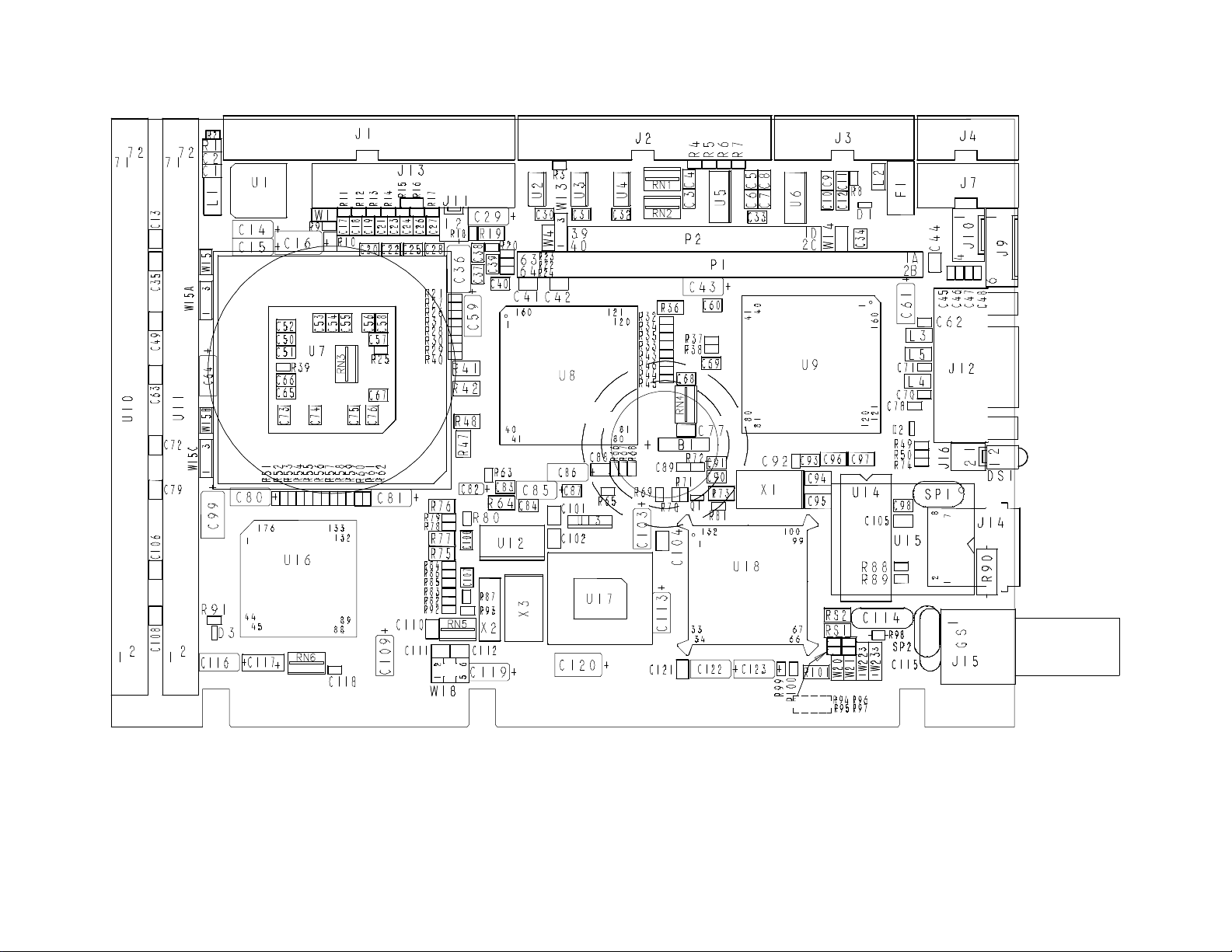
DIAGRAM 2-1: Assembly (Top)
Installing Memory 2-3
Page 22

DIAGRAM 2-2: Assembly (Bottom)
Installing Memory 2-5
Page 23

2.02 SIMM CONFIGURATION & INSTALLATION
At least 1MB of system memory must be installed on the VIPer808 for proper operation.
Total System Memory can be configured as 1MB, 2MB, 3MB, 4MB, 8MB, 12MB, 16MB,
32MB, 48MB, 64MB or 128MB using 36-bit SIMM devices.
There are two SIMM (Single In-line Memory Module) sockets; these can accept the
following 36-bit modules:
• 256K x 36-bit = 1MB module,
• 512K x 36-bit = 2MB module,
• 1M x 36-bit = 4MB module,
• 2M x 36-bit = 8MB module,
• 4M x 36-bit = 16MB module, and
• 8M x 36-bit = 32MB module.
Note: The VIPer808 board, will also support a total of 128MB of System Memory
when 64MB modules will be available.
Consult the table on the following page to see which SIMM configurations are available
on the VIPer808.
DRAM devices with page mode at 70ns maximum access time is recommended. Please
refer to Appendix E for a list of recommended devices.
When you are ready to install the SIMMs in the sockets, follow the steps outlined below.
• With the board flat on the table, turn it so that the end of the board with the sockets is
near you.
• Hold the module with the notch on the bottom right facing you, and insert the
connector into the socket at a 70° angle from the board (pin 1 on the module lines up
with pin 1 on the socket).
• Snap the module forward to a vertical position in the socket. The module is fully
inserted when the retaining pegs snap into the holes at each end of the module.
Installing Memory 2-7
Page 24

TABLE 2-1: SIMM Configuration
Total System
Memory
1MB 1MB (256Kx36) -1MB -- 1MB (256Kx36)
2MB 1MB (256Kx36) 1MB (256Kx36)
2MB 2MB (512Kx36) -2MB -- 2MB (512Kx36)
3MB 1MB (256Kx36) 2MB (512Kx36)
3MB 2MB (512Kx36) 1MB (256Kx36)
4MB 2MB (512Kx36) 2MB (512Kx36)
4MB 4MB (1Mx36) -4MB -- 4MB (1Mx36)
8MB 4MB (1Mx36) 4MB (1Mx36)
8MB 8MB (2Mx36) --
8MB -- 8MB (2Mx36)
12MB 4MB (1Mx36) 8MB (2Mx36)
12MB 8MB (2Mx36) 4MB (1Mx36)
16MB 8MB (2Mx36) 8MB (2Mx36)
16MB 16MB (4Mx36) -16MB -- 16MB (4Mx36)
32MB 16MB (4Mx36) 16MB (4Mx36)
32MB 32MB (8Mx36) -32MB -- 32MB (8Mx36)
48MB 16MB (4Mx36) 32MB (8Mx36)
48MB 32MB (8Mx36) 16MB (4Mx36)
64MB 32MB (8Mx36) 32MB (8Mx36)
64MB 64MB (16Mx36) -64MB -- 64MB (16Mx36)
128MB 64MB (16Mx36) 64MB (16Mx36)
U11 Socket - Bank 0 / 2
SIMM Module Installed
U10 Socket - Bank 1 / 3
SIMM Module Installed
Installing Memory 2-8
Page 25

SECTION 3
SETTING JUMPERS
This Section describes how to configure hardware options by setting jumper switches on
the VIPer board.
3.01 TERMINOLOGY
Jumper switches are small pins that you can set by using jumper caps. Two pins can be
joined by a jumper cap, thereby closing or shorting a circuit. So you short (or close) a
jumper by placing a plastic jumper cap over two pins of the jumper switch, and you open
a jumper switch by removing a jumper cap.
3.02 JUMPER LOCATIONS ON THE BOARD
Diagram 3-1 on the next page shows 13 jumpers. These appear as rectangular boxes
containing small circles which represent the pins. The jumpers are labeled on the board as
well. When there are more than two pins in a jumper, then some of the pins are also
numbered on the diagram and on the board, so that it will be possible to locate each pin
and its number.
Setting Jumpers 3-1
Page 26
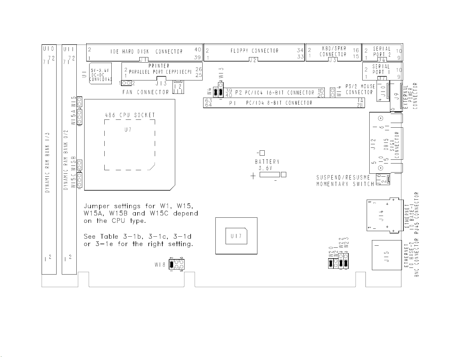
DIAGRAM 3-1: VIPer808 Jumper Locations with Default Settings
Setting Jumpers 3-3
Page 27

3.03 JUMPER SETTINGS
Table 3-1a to 3-1f on the following pages 3-6 to 3-11 show the jumper settings.
Setting Jumpers 3-5
Page 28

TABLE 3-1a: Jumper Settings: W1, W4, W13, W14
Setting Jumpers 3-6
Page 29
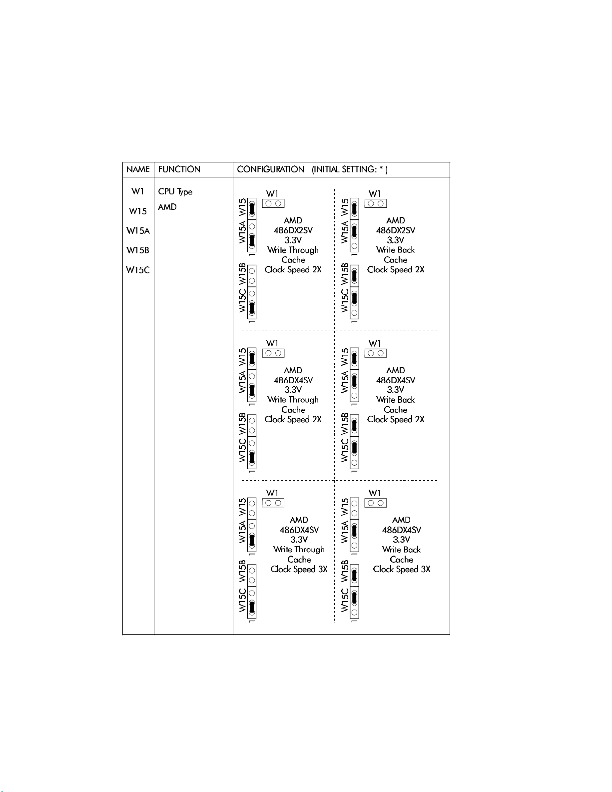
TABLE 3-1b: AMD DX2-DX4 CPU Jumper Settings: W1, W15-W15C
Setting Jumpers 3-7
Page 30
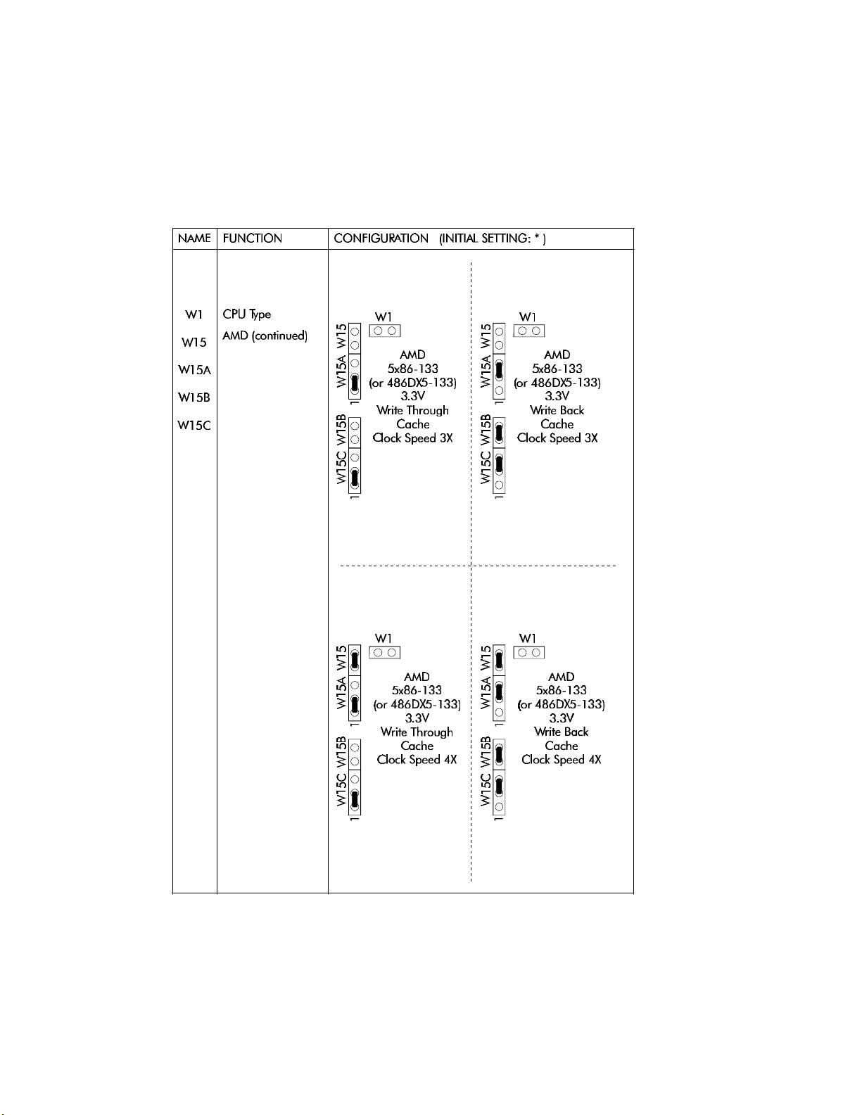
TABLE 3-1c: AMD 5x86 CPU Jumper Settings: W1, W15-W15C
Setting Jumpers 3-8
Page 31
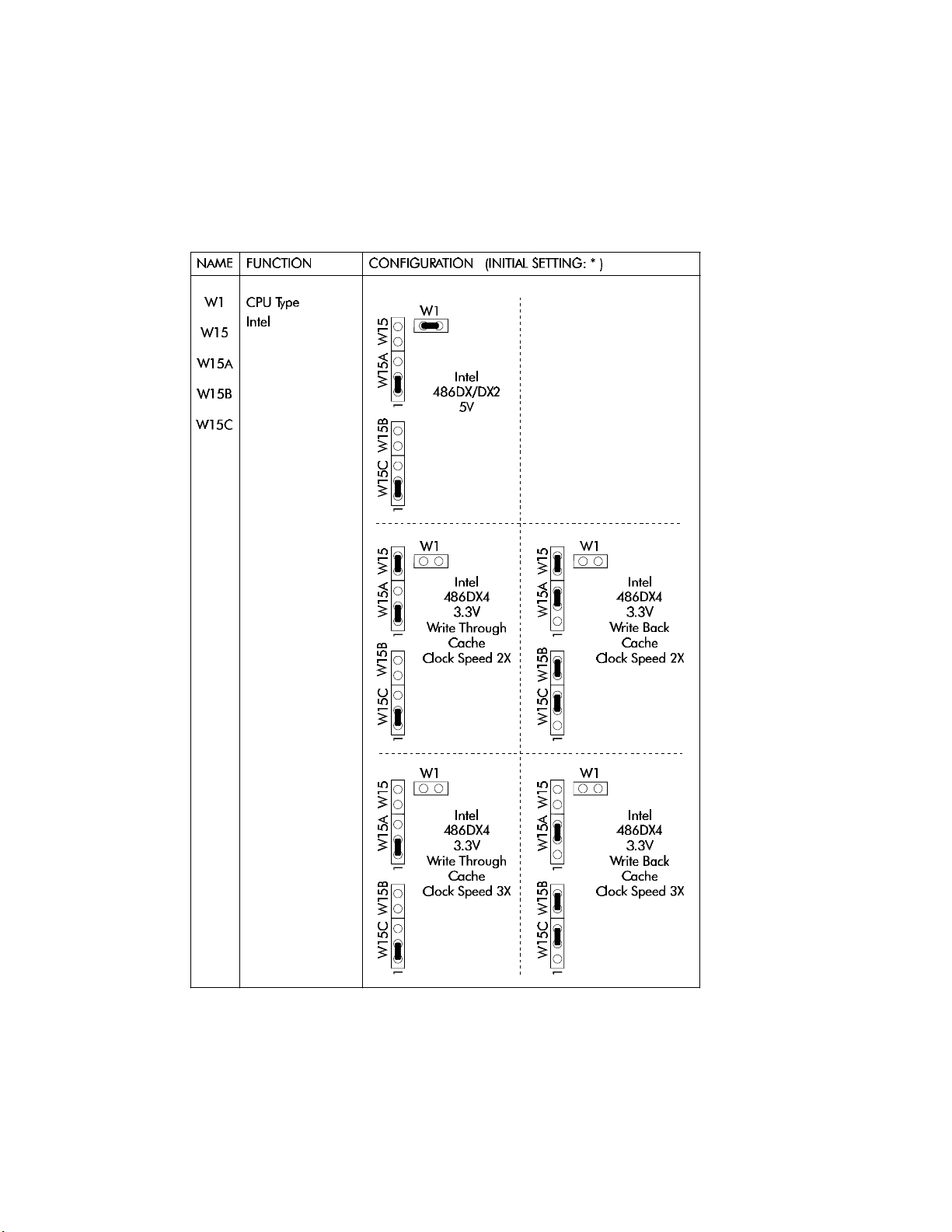
TABLE 3-1d: Intel CPU Jumper Settings: W1, W15-W15C
Setting Jumpers 3-9
Page 32
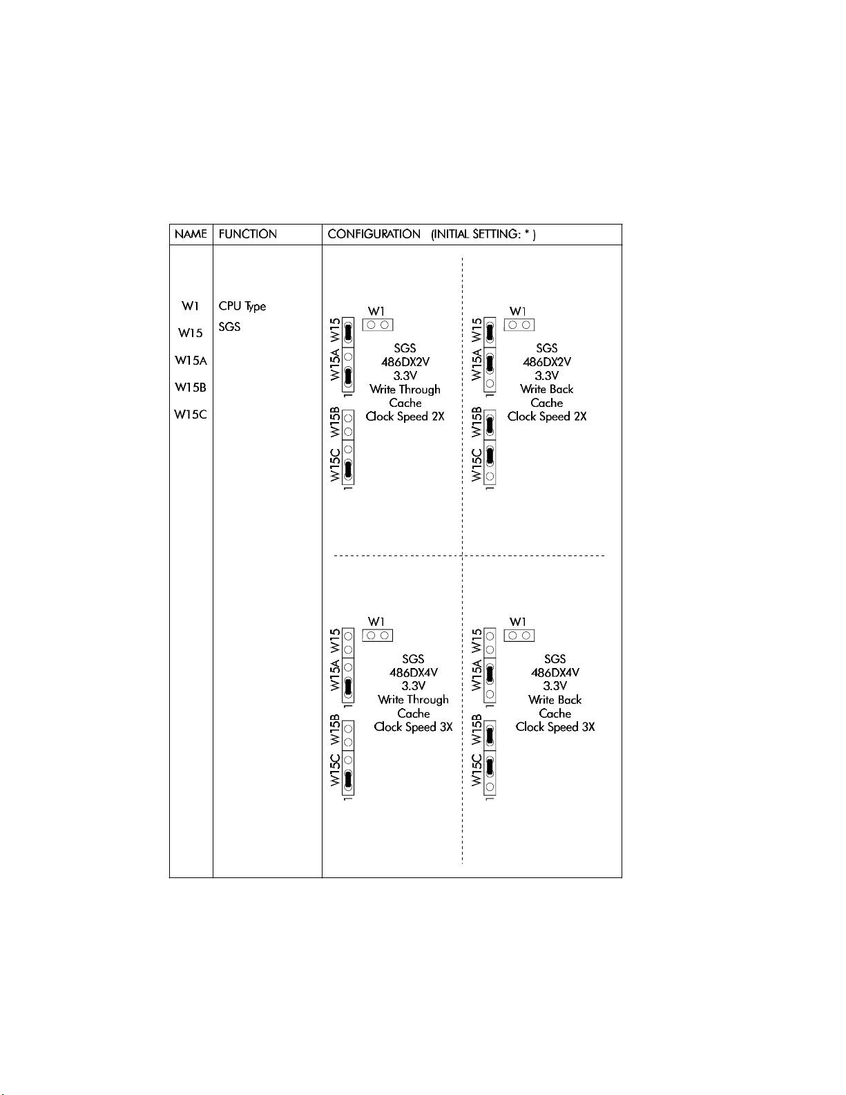
TABLE 3-1e: SGS CPU Jumper Settings: W1, W15-W15C
Setting Jumpers 3-10
Page 33
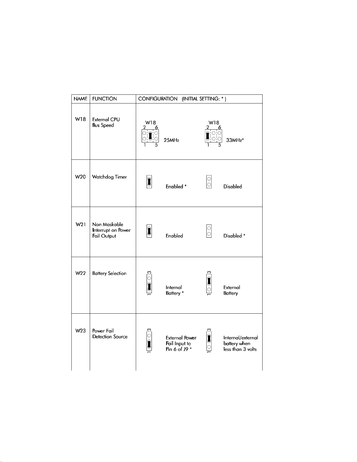
TABLE 3-1f: Jumper Settings: W18, W20-W23
Setting Jumpers 3-11
Page 34

SECTION 4
INSTALLING & WORKING WITH SYSTEM COMPONENTS
4.01 MICROPROCESSOR & FAN
4.01.1 MICROPROCESSOR
The VIPer808 supports the following microprocessors (maximum internal CPU clock
speed and CPU voltage are indicated):
• AMD 486DX2SV running at 66 MHz (3.3V);
• AMD 486DX4SV running at 100 MHz (3.3V);
• AMD 5x86 running at 133 MHz (3.3V) .
This processor is also referred to a 486DX5;
• Intel 486DX running at 33 MHz (5V);
• Intel 486DX2 running at 66 MHz (5V);
• Intel 486DX4 running at 100 MHz (3.3V);
• SGS 486DX2V running at 66 MHz (3.3V);
• SGS 486DX4V running at 100 MHz (3.3V).
The Math Co-processor is internal to the CPU (Central Processing Unit).
The above processors also have Internal Cache Memory available.
The following jumpers are related to the CPU:
• W1: Selects the voltage for powering CPU:
- Shorted: 5V,
- Or open: 3.3V.
WARNING: Incorrect CPU voltage can damage your CPU!
• W18: Selects the desired external CPU bus speed:
- W18 pins 3 and 4 shorted: 25MHz,
- Or W18 pins 1 and 2 shorted: 33MHz.
• W15A, W15B and W15C: These jumpers are used in conjunction with W15 to select
CPU Type. See Jumper Settings tables in Section 3 for supported types and their
settings.
Installing & Working With System Components 4-1
Page 35

• W15: Selects the desired multiplier to set the internal CPU clock speed (2, 3 or 4
times the external bus speed):
- Shorted: 2X (or 4X for AMD 5x86-133 only),
- Or open: 3X.
For DX microprocessors, external bus speed is set to the maximum CPU internal clock
speed or less.
For DX2 microprocessors, external bus speed is set to half the maximum CPU internal
clock speed or less.
For DX4 microprocessors, external bus speed is set to one third the maximum CPU
internal clock speed or less.
For 5x86 microprocessors, external bus speed is set to one fourth the maximum CPU
internal clock speed or less.
Jumper locations and settings appear in Section 3 of this manual.
4.01.2 CPU FAN
You must use a 5V CPU fan on the VIPer808. Pin 1 of the fan connector at J11 is supplied
with 5V (not 12V). A 5V CPU fan assembly (including cables) is available from
TEKNOR.
IMPORTANT: Use a 5V CPU fan on the VIPer808.
Installing & Working With System Components 4-2
Page 36

4.02 CONFIGURING CACHE
The microprocessors have Internal Cache Memory available for faster execution of
applications.
Cache copies the most recently accessed data and places it in its fast Internal Cache
Memory. The CPU can then access this data at a very high speed. Since most program
executions are sequential and repetitive, the likelihood is great that the CPU will find data
already stored in Cache.
When the CPU retrieves data from Cache, a Cache hit occurs. On the other hand, when
the CPU must access data from System Memory, a Cache miss occurs .
Internal Cache Memory is enabled or disabled in the Advanced Setup screen of the
AMIBIOS Setup program. To run the AMIBIOS Setup program, boot-up your computer
and hit the DELETE key before or when the message - "Hit <DEL> if you want to run
SETUP" - appears near the top of the screen. Set the Internal Cache option in the
Advanced Setup screen to Enabled or Disabled.
Internal Cache Memory is configured as Write Through or Write Back with VIPer808
jumpers. The jumper settings for various CPUs appear on pages 3-7 to 3-10.
Installing & Working With System Components 4-3
Page 37

4.03 SYSTEM CONTROLLER OVERVIEW
The PicoPower (Cirrus Logic subsidiary) PT86C768/PT86C718 System Controller used
on the VIPer808 board is a two-chip solution packaged in 176-pin VQFP’s. This chipset
contains power management features making it ideal for designing energy efficient
computer systems and high performance applications.
The System Controller was designed to support 32-bit 486 CPUs, capitalizing on the
unique features found in the SL-Enhanced series. It incorporates PicoPower’s Power On
Demand technology, providing unsurpassed power management features (explained in
section 8).
The System Controller also includes features like a high performance DRAM Controller,
Clock and Reset Interface, a Local Bus IDE Drive Interface for high performance disk
subsystem, and integrated 82C206 functions.
The System Controller is 100% IBM PC/AT compatible. It includes three 8254
Counter/Timers, two 8237 DMA Controllers and two 8259 Interrupt Controllers.
4.03.1 DMA CONTROLLERS
The VIPer808 supports seven Direct Memory Access (DMA) channels. The parallel port's
ECP mode can be configured to use Channel 1 or 3. Channel 2 is reserved for the Floppy
controller. Channel 4 is used to cascade Channels 0 through 7 to the microprocessor.
Channel 5 is available for the Ethernet port. Note that with Plug and Play, DMA channels
for I/O devices and the Ethernet can be modified via software per system requirements.
TABLE 4-1: 8237 DMA Controllers
DMA 0 Available
DMA 1 Available (ECP)
DMA 2 Floppy controller
DMA 3 Available (ECP)
DMA 4 Cascade controller # 1
DMA 5 Available (Ethernet)
DMA 6 Available
DMA 7 Available
Installing & Working With System Components 4-4
Page 38

4.03.2 INTERRUPT CONTROLLERS
Two 8259 interrupt controllers handle the interrupts on the VIPer808. Six interrupt lines
are directly linked to the keyboard controller, timer, the real-time clock, both serial ports
and the parallel port. Note that with Plug and Play, interrupt lines for I/O devices and the
Ethernet can be modified via software per system requirements.
TABLE 4-2: 8259 Interrupt Controllers
CONTROLLER # 1 CONTROLLER # 2
IRQ 0 Timer 0 IRQ 8 Real-time clock
IRQ 1 Keyboard IRQ 9 Available (Ethernet)
IRQ 2 Cascade controller # 2 IRQ 10 Available
IRQ 3 COM 2* IRQ 11 Available
IRQ 4 COM 1* IRQ 12 PS/2 Mouse
IRQ 5 Available (LPT2)* IRQ 13 Coprocessor
IRQ 6 Floppy controller* IRQ 14 IDE*
IRQ 7 LPT 1* IRQ 15 Available
* All functions marked with an asterisk (*) can be disabled or reconfigured.
4.03.3 COUNTER/TIMERS
There are three independent 16-bit 8254 Counter/Timers: Counter/Timer 0 is tied to
Interrupt 0, Counter/Timer 1 is used to generate the refresh with DMA Channel 0, and
Counter/Timer 2 is used for the Speaker Port.
Installing & Working With System Components 4-5
Page 39

4.04 MULTI-FUNCTION CONNECTOR (KEYBOARD, SPEAKER, RESET &
LED)
Connector J3 on the VIPer provides all the necessary signals for connecting the keyboard,
speaker, reset, and keylock interface devices. The following diagram shows the signal
connections at J3 (referred to as the Keyboard / Speaker Connector):
TABLE 4-3: Keyboard / Speaker Connector (J3)
Pin Number Pin Number
Signal Flow Signal Flow
Signal Signal
KBCLK I/O 1 2 - GND
KBDATA I/O 3 4 - GND
VCC (+5V) - 5 6 - VCC (+5V)
SPKR O 7 8 - VCC (+5V)
KBDINH I 9 10 - GND
Not Connected - 11 12 - GND
PBRES* I 13 14 - GND
HDD ACTIVE O 15 16 - VCC (+5V)
* Active low signal
The following functions are available on the connector:
• Speaker: An 8 ohm speaker can be directly connected to pins 7 and 8 of J3. All
necessary drivers are on the VIPer.
• Keyboard Disable: The keyboard can be disabled or locked up by shorting pins 9 and
10 of J3.
• Hard Disk LED: The onboard IDE interface activates an external LED. The LED
must be connected anode on pin 16 (J3) and cathode on pin 15 (J3). No external
current limiting resistor is required since one is already present on the VIPer.
• Reset: The VIPer can be reset by shorting pins 13 and 14 of J3.
Installing & Working With System Components 4-6
Page 40

4.05 PC/104 EXPANSION CARDS
The VIPer808 was designed with provisions for PC/104 connectors, which are available as
an option. PC/104 offers full architecture, hardware and software compatibility with PC
Bus, in ultra-compact stackable modules (3.6" x 3.8"). PC/104 is being advanced as a
proposed Appendix to the IEEE-P996 draft specification. Products compatible with the
PC/104 are already offered by over 70 companies.
If you require additional information on the PC/104 standard, please contact our
Technical Support department.
4.06 PS/2 MOUSE
The board supports a mouse, through the PS/2 connector at J10. With the PS/2 Mouse
Cable (available from TEKNOR), this feature is compatible with the standard IBM PS/2
mouse. The cable may be ordered by contacting our Sales department.
During installation of the mouse, you must install the driver provided by the mouse
manufacturer.
To enable the mouse, set the Mouse Support option to Enabled in the Advanced Setup
screen of the AMIBIOS Setup program.
Installing & Working With System Components 4-7
Page 41

SECTION 5
INSTALLING PERIPHERALS (PARALLEL/SERIAL/ETHERNET)
5.01 PARALLEL PORT
5.01.1 MODES
The parallel port is a multi-mode parallel port supporting the following modes:
• Standard Parallel Port (SPP): This mode is IBM XT/AT compatible and PS/2
compatible (bi-directional);
• Enhanced Parallel Port (EPP);
• Extended Capabilities Port (ECP).
Installing Peripherals (Parallel/Serial/Ethernet) 5-1
Page 42

5.01.2 CONNECTOR
The parallel port connector (J13) is a male 26-pin header located at the top left side of the
board.
The following table shows the pinout for this connector, when it is in Standard mode:
TABLE 5-1: Printer Parallel Port (J13) - Standard Mode
Pin Number Pin Number
Signal Flow Signal Flow
Signal Signal
STROBE* O 1 2 O AUTOFD*
D0 I/O 3 4 I ERROR*
D1 I/O 5 6 O INIT*
D2 I/O 7 8 O SELECTIN*
D3 I/O 9 10 - GND
D4 I/O 11 12 - GND
D5 I/O 13 14 - GND
D6 I/O 15 16 - GND
D7 I/O 17 18 - GND
ACK* I 19 20 - GND
BUSY I 21 22 - GND
PE I 23 24 - GND
SELECT I 25 26 - GND
* Active low signal
Installing Peripherals (Parallel/Serial/ Ethernet) 5-2
Page 43

The following table shows the pinout for this connector, when it is in EPP mode:
TABLE 5-2: Printer Parallel Port (J13) - EPP Mode
Pin Number Pin Number
Signal Flow Signal Flow
Signal Signal
WRITE* O 1 2 O DATASTB*
D0 I/O 3 4 - Not Used
D1 I/O 5 6 - Not Used
D2 I/O 7 8 O ADDRSTRB*
D3 I/O 9 10 - GND
D4 I/O 11 12 - GND
D5 I/O 13 14 - GND
D6 I/O 15 16 - GND
D7 I/O 17 18 - GND
INTR I 19 20 - GND
WAIT* I 21 22 - GND
Not Used - 23 24 - GND
Not Used - 25 26 - GND
* Active low signal
Installing Peripherals (Parallel/Serial/Ethernet) 5-3
Page 44

The following table shows the pinout for this connecter, when it is in ECP mode:
TABLE 5-3: Printer Parallel Port (J13) - ECP Mode
Pin Number Pin Number
Signal Flow Signal Flow
Signal Signal
STROBE* O 1 2 O AUTOFD*,
D0 I/O 3 4 I FAULT*1,
D1 I/O 5 6 O INIT*1,
D2 I/O 7 8 O SELECTIN*
D3 I/O 9 10 - GND
D4 I/O 11 12 - GND
D5 I/O 13 14 - GND
D6 I/O 15 16 - GND
D7 I/O 17 18 - GND
ACK* I 19 20 - GND
BUSY, PERIPHACK3I 21 22 - GND
PERROR,
ACKREVERSE
SELECT I 25 26 - GND
* Active low signal
1
Compatible Mode
2
High Speed Mode
I 23 24 - GND
3
HOSTACK
PERIPHRQST*
REVERSERQST*
3
1,3
3
3
Note: For more information on the ECP protocol, please refer to the Extended Capabilities
Port Protocol and ISA Interface Standard (available from Microsoft Corporation) or
contact our Technical Support department.
Installing Peripherals (Parallel/Serial/ Ethernet) 5-4
Page 45

5.01.3 AMIBIOS SETUP
Follow these steps, from the AMIBIOS Setup program’s main menu:
• From the Setup window, select the Peripheral icon.
• In the Peripheral Setup screen, these options may be set: ONBOARD PARALLEL
PORT, PARALLEL PORT IRQ, PARALLEL PORT MODE and PARALLEL PORT
DMA CHANNEL.
For more detail, refer to section 9.01 - AMIBIOS SETUP PROGRAM.
Installing Peripherals (Parallel/Serial/Ethernet) 5-5
Page 46

5.02 SERIAL PORTS
There are two 16550 compatible serial ports. These have internal 16-byte FIFO buffers for
more efficient data transfers.
Installing Peripherals (Parallel/Serial/ Ethernet) 5-6
Page 47

5.02.1 CONNECTORS
Serial Port 1 (J7) RS-232
The Serial Port 1 is configured as RS-232, and is 100% compatible to the IBM-AT serial
port, with the use of the IBM 9-pin DSUB Standard. The following tables show their
pinouts:
TABLE 5-4a: Serial Port 1 (J7) RS-232
Pin Number Pin Number
Signal Flow Signal Flow
Signal Signal
DCD I 1 2 I DSR
RX I 3 4 O RTS
TX O 5 6 I CTS
DTR O 7 8 I RI
GND - 9 10 - Not Connected
TABLE 5-4b: IBM 9-Pin DSUB Standard
Pin Number Pin Number
Signal Flow Signal Flow
Signal Signal
DCD I 1 2 I RX
TX I 3 4 O DTR
GND - 5 6 I DSR
RTS O 7 8 I CTS
RI I 9
TEKNOR offers a 10-pin header to 9-pin DSUB cable for IBM-AT compatibility. This
can be purchased from TEKNOR or a cable can be made with a flat cable, a 10-pin flat
cable crimp header and a 9-pin DSUB flat cable crimp connector. The use of Taïwanese
adapter cables is not recommended, since the pinout is often incorrect. The direct crimp
design offered by TEKNOR allows the simplest cable assembly. All these cables are
available from TEKNOR by contacting the Sales department.
Installing Peripherals (Parallel/Serial/Ethernet) 5-7
Page 48

Serial Port 2 (J4) RS-232
The Serial Port 2 is configured as RS-232, and is 100% compatible to the IBM-AT serial
port, with the use of the IBM 9-pin DSUB Standard. The following tables show their
pinouts:
TABLE 5-5a: Serial Port 2 (J4) RS-232
Pin Number Pin Number
Signal Flow Signal Flow
Signal Signal
DCD I 1 2 I DSR
RX I 3 4 O RTS
TX O 5 6 I CTS
DTR O 7 8 I RI
GND - 9 10 - Not Connected
TABLE 5-5b: IBM 9-Pin DSUB Standard
Pin Number Pin Number
Signal Flow Signal Flow
Signal Signal
DCD I 1 2 I RX
TX I 3 4 O DTR
GND - 5 6 I DSR
RTS O 7 8 I CTS
RI I 9
TEKNOR offers a 10-pin header to 9-pin DSUB cable for IBM-AT compatibility. This
can be purchased from TEKNOR or a cable can be made with a flat cable, a 10-pin flat
cable crimp header and a 9-pin DSUB flat cable crimp connector. The use of Taïwanese
adapter cables is not recommended, since the pinout is often incorrect. The direct crimp
design offered by TEKNOR allows the simplest cable assembly. All these cables are
available from TEKNOR by contacting the Sales department.
Installing Peripherals (Parallel/Serial/ Ethernet) 5-8
Page 49

5.02.2 AMIBIOS SETUP
Follow these steps, from the AMIBIOS Setup program’s main menu:
• From the Setup window, select the Peripheral icon.
• In the Peripheral Setup screen, these options may be set: ONBOARD SERIAL PORT
1 and ONBOARD SERIAL PORT 2.
For more detail, refer to section 9.01 - AMIBIOS SETUP PROGRAM.
Installing Peripherals (Parallel/Serial/Ethernet) 5-9
Page 50

5.03 ETHERNET PORT
5.03.1 ETHERNET FEATURES
The onboard Ethernet controller and port has these features:
ù Supports IEEE 802.3 / ANSI 8802-3 and Ethernet standards.
ù Individual 136-byte transmit and 128-byte receive FIFOs optimize system overhead,
providing sufficient latency during packet transmission and reception, and minimizing
intervention during normal network error recovery.
ù Supports Microsoft’s Plug and Play System configuration for jumperless designs.
Information stored in the serial EEPROM is used to identify the card and to describe
the system resources required by the Plug and Play card, such as I/O space, Memory
space, IRQs and DMA channels. This information is stored in a standardized read only
format.
Installing Peripherals (Parallel/Serial/ Ethernet) 5-10
Page 51

5.03.2 SETTING UP ETHERNET
Cabling
The VIPer808 is configured with either the Ethernet 10 Base-T or 10 Base-2 interface.
The 10 Base-T interface uses UTP (Unshielded Twisted Pair) cables, category 5,4 or 3 (5
is better). The 10 Base-2 interface uses Thin Ethernet coaxial cables (RG-58). The
impedance is 50 ohms.
Configuration
The Ethernet controller on the VIPer808 is Plug and Play, therefore no manual
configuration is normally required. A diskette entitled “Network Drivers for AM79C961”
is included with the Ethernet option. This diskette contains several operating system
network drivers. You must refer to the READ_NET.TXT (ASCII) or READ_NET.DOC
(WORD 6.0) file, also on the diskette, for instructions on installing the drivers.
Once the proper Ethernet driver is installed, the onboard Plug and Play BIOS and the
driver automatically allocates resources - I/O addresses, IRQ and DMA channels - to the
Ethernet device.
In some cases, it might be absolutely necessary to manually configure the Ethernet
Controller. This is the case when several ISA cards (non Plug and Play) use resources that
might be allocated to the Ethernet controller. A special utility called the PCNETCFG.EXE
was designed for such situations; it will allow you to manually configure the Ethernet
controller.
For the PCNETCFG.EXE utility, other operating system drivers and installation
instructions, or for more information, contact TEKNOR’s Technical Support department.
Installing Peripherals (Parallel/Serial/Ethernet) 5-11
Page 52

5.03. 3 CONNECTORS
The pinout for the 10 Base-T connector appears in Table 5-7.
TABLE 5-6: Ethernet 10 Base-T RJ45 Connector (J14) - Pinout
Pin Number Pin Number
Signal Flow Signal Flow
Signal Signal
TXD+ O 1 5 - Not Connected
TXD- O 2 6 I RXD-
RXD+ I 3 7 - Not Connected
Not Connected - 4 8 - Not Connected
The Ethernet 10 Base-2 Connector (J15) is a standard BNC connector.
Installing Peripherals (Parallel/Serial/ Ethernet) 5-12
Page 53

SECTION 6
INSTALLING IDE & FLOPPY DEVICES
6.01 INSTALLING IDE DEVICES
6.01.1 TYPE OF HARD DISK SUPPORTED
The VIPer808 supports AT Integrated Disk Drives. The AT embedded drive architecture
incorporates drive electronics and controller circuitry on a single printed circuit board
which is mounted directly to the disk drive chassis.
The integration of drive and controller functions increases reliability and performance by
eliminating redundant circuitry, thus providing increased performance at reduced cost.
Installing IDE & Floppy Devices 6-1
Page 54

6.01.2 IDE CONNECTOR PINOUT
TABLE 6-1: IDE Hard Disk Connector (J1) - Pinout
Pin
Number
1
3
5
7
9
11
13
15
17
19
21
23
25
27
29
31
33
35
37
39
Signal
Flow
I
I/O
I/O
I/O
I/O
I/O
I/O
I/O
I/O
-
I
I
O
O
I
I
I
O
Signal Pin
RESET*
HD7
HD6
HD5
HD4
HD3
HD2
HD1
HD0
GND
Not Connected
IOW*
IOR*
IOCHRDY
Not Connected
IRQ14
SA1
SA0
CS0*
ACTIVE*
Number
2
4
6
8
10
12
14
16
18
20
22
24
26
28
30
32
34
36
38
40
Signal
Flow
I/O
I/O
I/O
I/O
I/O
I/O
I/O
I/O
-
-
-
I
O
I
I
-
Signal
GND
HD8
HD9
HD10
HD11
HD12
HD13
HD14
HD15
Not Connected
GND
GND
GND
BALE
GND
IOCS16*
Not Connected
SA2
CS1*
GND
* Active low signal
6.01.3 IDE HOOK-UP
For the hook-up, a 40-pin dual row header signal connector is required. This connector
handles all command, data and status I/O lines. Its recommended maximum cable length
is 18-24 inches. It connects directly with the onboard 40-pin male header connector at J1.
The drive itself can be mounted in any horizontal or vertical plane.
For a list of recommended devices and connectors, see Appendix E - RECOMMENDED
DEVICES & MATING CONNECTORS.
Installing IDE & Floppy Devices 6-2
Page 55

6.01.4 IDE JUMPER
IDE Controller jumper and its setting appears below:
• W14 IOCHRDY signal to IDE interface:
- Shorted: Enabled.
- Or open:Disabled: This is the initial setting.
For location and setting of jumper, refer to Section 3 of this manual.
Installing IDE & Floppy Devices 6-3
Page 56

6.01.5 IDE SOFTWARE SETUPS
AMIBIOS Setup
Follow these steps, from the AMIBIOS Setup program's main menu:
• From the Setup window, select the Standard icon.
• From the Standard Setup screen, select the appropriate hard disk drive icon.
• For each hard disk, these options can be defined: TYPE, LBA/LARGE MODE,
BLOCK MODE, 32BIT MODE and PIO MODE. TYPE and PIO MODE can be Auto
detected if the hard disk drive is an IDE drive: the Auto option automatically finds all
of the IDE drive parameters for that hard disk. You should check your hard disk data
sheets to know if any of the other options - LBA/LARGE MODE, BLOCK MODE
and 32BIT MODE - should be set to ON; if your hard disk supports these modes,
enabling them will optimize your system.
• Return to the main menu, and select the Chipset icon from the Setup window.
• From the Chipset Setup screen, you can set these options: TURBO IDE FUNCTION,
ONBOARD IDE COMMAND WIDTH and ONBOARD IDE BACK TO BACK
DELAY.
• Return to the main menu, and select the Peripheral icon from the Setup window.
• In the Peripheral Setup screen, the ONBOARD IDE option may be set to Primary,
Secondary or Disabled.
For more detail, refer to section 9.01 - AMIBIOS SETUP PROGRAM.
Installing IDE & Floppy Devices 6-4
Page 57

6.02 INSTALLING FLOPPY DEVICES
6.02.1 TYPES OF FLOPPY DEVICES SUPPORTED
The floppy disk controller is IBM PC XT/AT compatible (single and double density) and
supports Enhanced Floppy Mode (2.88MB). It handles 3.5 inch and 5.25 inch, low and
high density drives. Up to two drives can be supported in any combination.
Installing IDE & Floppy Devices 6-5
Page 58

6.02.2 FLOPPY CONNECTOR
TABLE 6-2: Floppy Connector (J2) - Pinout
Pin
Number
1
3
5
7
9
11
13
15
17
19
21
23
25
27
29
31
33
Signal
Flow
-
-
-
-
-
-
-
-
-
-
-
-
-
-
-
-
-
* Active low signal
Signal Pin Number Signal
GND
GND
GND
GND
GND
GND
GND
GND
Not Connected
GND
GND
GND
GND
Not Connected
Not Connected
GND
Not Connected
2
4
6
8
10
12
14
16
18
20
22
24
26
28
30
32
34
Flow
O
-
I
O
O
O
O
O
O
O
O
I
I
I
O
I
Signal
DRV DENS.SEL.0*
Not Connected
Not Connected
INDEX*
MOTOR ON 0*
DRIVE SELECT B*
DRIVE SELECT A*
MOTOR ON 1*
DIR CONTROL*
STEP*
WRITE DATA*
WRITE ENABLE*
TRACK0*
WRITE PROTECT*
READ DATA*
HEAD SELECT*
DSKCHG*
6.02.3 FLOPPY HOOK-UP
Installing IDE & Floppy Devices 6-6
Page 59
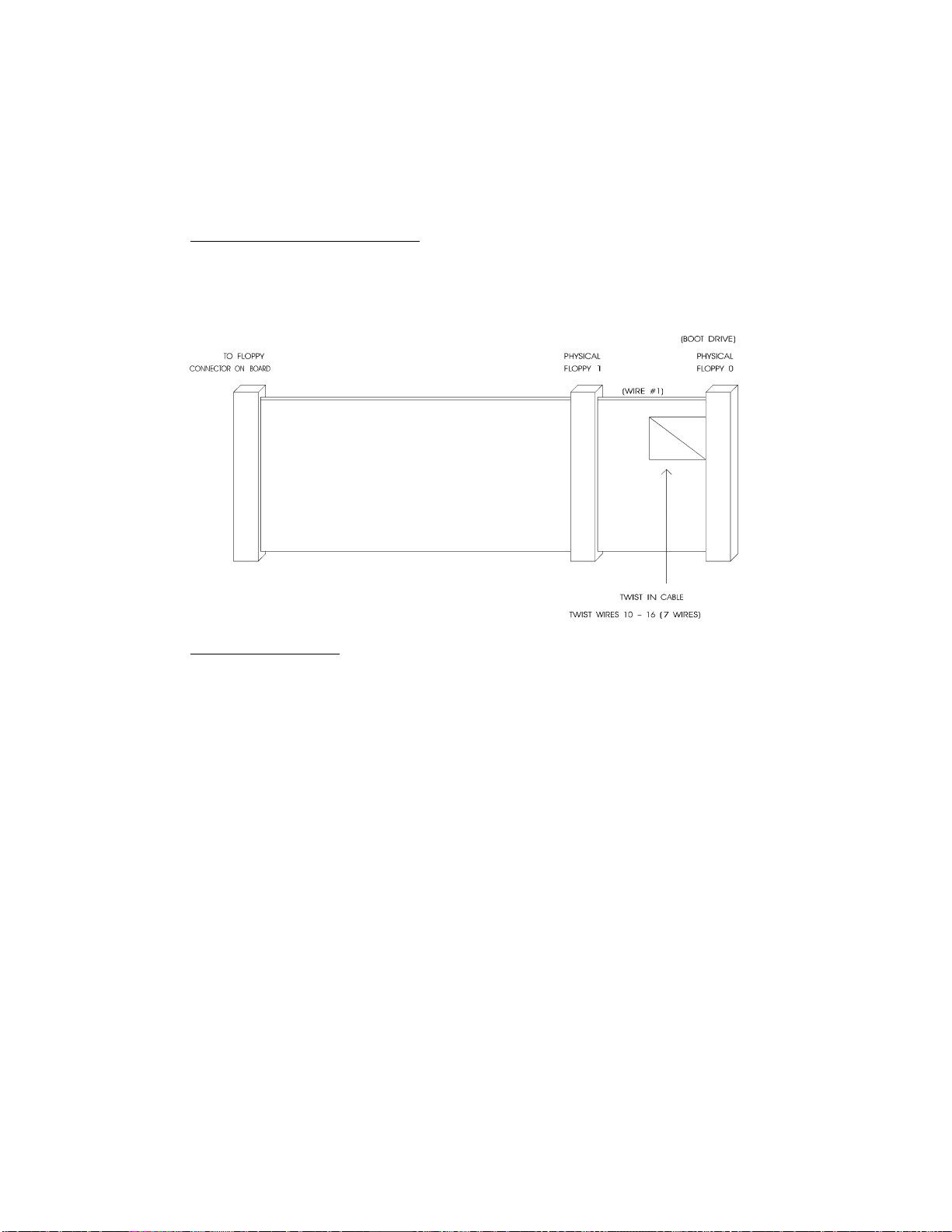
Mechanical Floppy Disk Installation:
The installation of the floppy drives is done via a standard IBM 34-pin flat ribbon cable
that connects to J2.
DIAGRAM 6-1: Floppy Disk Cable
Enhanced Floppy Mode:
In order to connect your 2.88MB floppy drive, simply indicate the proper floppy disk drive
in the AMIBIOS Setup program (Section 9).
Installing IDE & Floppy Devices 6-7
Page 60

6.02.4 FLOPPY AMIBIOS SETUP
Follow these steps, from the AMIBIOS Setup program's main menu:
• From the Setup window, select the Standard icon.
• From the Standard Setup screen, select the Floppy A icon (or the Floppy B icon).
• The settings are 360KB 5¼ inch, 1.2MB 5¼ inch, 720KB 3½ inch, 1.44MB 3½ inch,
or 2.88MB 3½ inch.
• Return to the main menu, and select the Peripheral icon from the Setup window.
• In the Peripheral Setup screen, the ONBOARD FDC option may be set to Auto,
Enabled (enable Floppy Drive Controller) or Disabled.
For more detail, refer to section 9.01 - AMIBIOS SETUP PROGRAM.
Installing IDE & Floppy Devices 6-8
Page 61

SECTION 7
INSTALLING VIDEO
The VIPer808 video system includes a local bus CRT video controller and 1MB of video
memory (optional 512KB).
7.01 CRT SVGA CONTROLLER
The VIPer808's CRT Super VGA controller is a single-chip video controller from Cirrus
Logic (CL-GD5429). It is fully compatible with the IBM VGA standard at the
hardware and BIOS level.
7.01.1 CRT SUPPORT
The video controller supports both monochrome and color VGA/SVGA displays with
resolution of up to 1280 x 1024 (256 colors). However, since the video controller outputs
only analog signals for CRT display, it will not drive TTL level signals. This means it
does not function with CGA, EGA and Hercules monitors.
7.01.2 DISABLING VIDEO
The video controller can be disabled by removing the W4 jumper. See Section 3 for
jumper location and settings.
This feature is useful when an external video card is required for testing or other purposes.
Installing Video 7-1
Page 62

7.02 CONNECTING CRT VIDEO DISPLAY
Connecting CRT video to the VIPer808 is simple. Merely connect the standard VGA
DB15 male connector to the board's J12 high density, right angle, female connector. See
Diagram 7-1 on the following page for the location of J12.
7.02.1 SVGA CONNECTOR (J12)
The VGA connector's pinout appears in Table 7-1.
TABLE 7-1: SVGA Connector (J12) - Pinout
Pin Number Signal Pin Number Signal Pin Number Signal
1 RED 6 GND 11 Not Connected
2 GREEN 7 GND 12 Not Connected
3 BLUE 8 GND 13 HSYNC
4 Not Connected 9 Not Connected 14 VSYNC
5 GND 10 GND 15 Not Connected
Installing Video 7-2
Page 63

SECTION 8
POWER MANAGEMENT
8.01 POWER SUPPLY SOURCE
The VIPer808 is powered from one of two sources:
• Power connector (J9): Stand-alone systems are powered from an outside power
supply
through the J9 connector.
• ISA (AT) bus: When the board is in a passive backplane system, it is
powered
through the ISA bus.
The pinout for the J9 power connector is shown in the table below:
TABLE 8-1: External Power Connector (J9) - Pinout
Pin Number Signal
1 VCC (+5V)
2 GND
3 GND
4 +12V
5 -12V
6 PD (Power Fail Detection Input)
Power Management 8-1
Page 64

8.02 POWER MANAGEMENT MODES
The VIPer808 supports a very flexible and powerful power management scheme. The
System Controller provides progressively higher levels of power conservation whenever
the system is idle through the following special power saving modes: Doze Mode, Sleep
Mode and Suspend Mode (power management test results are given in Table A-2 on page
A-2). These modes are fully programmable through the AMIBIOS Setup Program.
The CPU power consumption is reduced through the STOPCLOCK protocol, which is
used to shut down the CPU’s internal clock during the various power management modes.
In general, each progressive level of power management is entered when inactivity is
detected by the System Controller which monitors activity from the Keyboard, Video,
Serial and Parallel I/O, and the Hard and Floppy Drives.
The timeouts which are used to enter into Doze Mode, then Sleep Mode, and finally
Suspend Mode, are programmable via the AMIBIOS Power Management Setup screen.
Each mode is described below.
8.02.1 DOZE MODE
The Doze Mode is the System Controller’s first level of power conservation. During Doze
Mode, the display and hard drive will remain active. In fact, this mode is transparent to
the user. Exit from Doze Mode is by a keypress or a serial port interrupt (e.g., mouse
movement). Exit from Doze Mode is immediate.
8.02.2 SLEEP MODE
The Sleep Mode is the System Controller’s second level of power conservation. During
Sleep Mode, the display becomes inactive and the hard drive motor is stopped. Exit from
Sleep Mode is by a keypress or a serial port interrupt (e.g., mouse movement). Exit from
Sleep Mode takes approximately 5 seconds.
8.02.3 SUSPEND MODE
The Suspend Mode is the System Controller’s third and deepest level of power
conservation. During Suspend Mode, the display and the hard drive motor remain
inactive. Exit from Suspend Mode is via a contact closure on the J16 Suspend / Resume
Momentary Switch Connector (see Diagram 7-1) or via the RING signal from an external
modem. Thus, if Suspend Mode is to be used, a Normally Open momentary switch should
be connected to this connector. Exit from Suspend Mode takes approximately 7 seconds.
Power Management 8-2
Page 65

8.03 RESET CIRCUIT
8.03.1 EXTERNAL RESET CIRCUIT SWITCH
The VIPer can be reset by activating an external reset switch.
This switch should be connected between pin 13 (PBRES*) and pin 14 (GND) on the
Keyboard / Speaker Connector (J3).
This provides an easy and effective way of resetting the system.
See Section 4.04 for more information.
8.03.2 ONBOARD POWER DETECTION
An onboard device, which is part of the reset circuit, constantly monitors the voltage
which powers the board. Normally, the board is powered with 5V; if the supply voltage
drops below 4.65V (a typical threshold), the onboard circuitry will reset the VIPer board
and the system. This reset has the same effect on the system as the reset button.
Power Management 8-3
Page 66

8.04 POWER FAIL DETECTION CIRCUIT
The Power Failure Detector always monitors:
• The backup battery to warn of a low battery condition, and
• The +5V power supply to detect when it falls below 4.75V.
If either of the two above conditions occur, the PFO (Power Fail Output signal) goes low.
In the case of the +5V power supply, a reset will result as explained in the previous
section (8.03.2). In the case of the low battery, what happens will depend on the setting of
the W21 jumper and user-defined algorithm.
The W21 jumper, when shorted, will generate a NMI (Non Maskable Interrupt), through
the IOCHK* line, when the PFO goes low. In turn, this NMI may be serviced by an
interrupt handler to locate the source and notify the user or the system.
If the W21 jumper is left open, no NMI is generated, however an algorithm could be used
to detect a low battery condition and respond accordingly. An example of such an userdefined program appears below.
INDEXREGISTER = 0x24;
DATAREGISTER = 0x26;
boolean Good;
word Data;
outport( INDEXREGISTER , 0x111 ); Set bit 13 Pin Select Register to Low;
Data = inport( DATAREGISTER ); that sets the GPIO1 pin to Enabled.
Data = Data &(~0x2000); Mask on bit 13.
outport( INDEXREGISTER , 0x111 );
outport( DATAREGISTER , Data );
outport( INDEXREGISTER , 0x007 ); Set bit 15 Gen. Purp.Ctrl Reg. to High;
Data = inport( DATAREGISTER ); that puts the GPIO1 pin in Input.
Data = Data &(~0x2000); Mask on bit 15.
outport( INDEXREGISTER , 0x007 );
outport( DATAREGISTER , Data );
Read the PF0 signal …
outport( INDEXREGISTER , 0x007 ); Read the GPIO1 signal (Pwr Fail 0utput).
Data = inport( DATAREGISTER ); If Good is True then the battery is OK,
If (Data & 0x200) Good = True; else the battery voltage is Low.
else Good = False;
Power Management 8-4
Page 67

The W22 jumper is used to select whether the battery is onboard (1-2) or external (2-3).
The W23 jumper is used to select what voltage is monitored:
• Short pins 1-2 to monitor an external voltage that is present on the power fail input,
through pin 6 of the J9 power connector,
• Or short pins 2-3 to monitor the internal/external battery.
There are three ways to set the Power Fail and Battery circuit:
• Using Internal Battery & Monitoring External Source:
Internal Battery (set by W22 jumper with pins 1-2 shorted) and External Power Fail
Input to Pin 6 of J9 connector (set by W23 jumper with pins 1-2 shorted).
The power detection input can only accept DC voltage. The line is monitored via a
resistor network made up of a user-defined resistor (R98) and a fixed 1KΩ resistor
connected to GND. The junction of these two resistors is connected to the input of the
power fail circuit which has its threshold set to 1.25V. R98 can be calculated as
follows:
R98 = 1KΩ (VI-1.25) where VI is input voltage on pin 6
1.25 of the power connector.
• Using Internal Battery & Monitoring Internal Battery:
Internal Battery (set by W22 jumper with pins 1-2 shorted) and Power fail detect when
battery is less than 3V (set by W23 jumper with pins 2- 3 shorted).
When the internal battery is selected as being the source of the power fail circuit, it is
set to trip when the battery goes lower that 3V.
• Using External Battery & Monitoring External Battery:
External Battery (set by W22 jumper with pins 2-3 shorted) and Power fail detect when
battery is less than 3V (set by W23 jumper with pins 2-3 shorted).
When the external battery is selected as being the source of the power fail circuit, it is
set to trip when the battery drops below 3V.
This means that when an external battery is used, the voltage needs to be monitored on the
battery.
Jumper locations and settings are illustrated in Section 3.
Power Management 8-5
Page 68

8.05 WATCHDOG TIMER
The Watchdog Timer is extremely useful in embedded systems where human supervision
is not required.
Following a reset, the Watchdog is always disabled. If a hardware or software failure
occurs such that the Watchdog is not refreshed, a reset pulse is generated by the Watchdog
to restart the processor.
Jumper W20 must be installed to permit activation of the Watchdog. If jumper W20 is
removed, the Watchdog is disabled.
An user-defined program such as the one appearing below, must also be used in order to
enable and refresh the Watchdog.
INDEXREGISTER = 0x24;
DATAREGISTER = 0x26;
word Data;
outport( INDEXREGISTER , 0x111 ); Set bit 15 of Select Register to Low;
Data = inport( DATAREGISTER ); that sets the GPIO3 pin to Enabled.
Data = Data &(~0x8000); Mask on bit 15.
outport( INDEXREGISTER , 0x111 );
outport( DATAREGISTER , Data );
outport( INDEXREGISTER , 0x007 ); Set bit 15 Gen. Purp. Ctrl Reg. to High;
Data = inport( DATAREGISTER ); that puts the GPIO3 pin in Output.
Data = Data | 0x8000; Mask on bit 15.
outport( INDEXREGISTER , 0x007 );
outport( DATAREGISTER , Data );
Every 1.6 second (at least), toggle the bit 11 of the GPIO3 pin.
outport( INDEXREGISTER , 0x007 ); Toggle GPIO3 pin for the Watchdog;
Data = inport( DATAREGISTER ); that puts the GPIO3 pin High or Low.
Data = Data ^ 0x800; Toggle bit 11 with XOR.
outport( INDEXREGISTER , 0x007 );
outport( DATAREGISTER , Data );
To disable the Watchdog, just put the bit 15 of the General Purpose Control
Register Low.
Power Management 8-6
Page 69

The default timeout period is 1.6 seconds; however the timeout period can be changed.
Shorting C173 and leaving R165 opened changes the timeout to 100 ms. Shorting R165
and installing a capacitor at C173 will change the timeout period according to the
following formulae:
Timeout (milliseconds) = (400/47pF) * C
or
C173 = (Timeout (milliseconds) * 47pF) / 400ms
For instance, an external capacity of 100pF will lengthen the timeout to 851ms and a
1000pF will bring it to 8.5 seconds.
Power Management 8-7
Page 70

SECTION 9
VIPer SOFTWARE SETUP
The VIPer808 is fully software configurable. The setup program allows for minimal
hardware configuration.
The AMIBIOS Setup program which is used to change operating parameters is explained
in section 9.01.
The procedure for updating or restoring the VIPer808 BIOS in the Boot-Block Flash is
given in section 9.02.
VIPer Software Setup 9-1
Page 71

9.01 AMIBIOS SETUP PROGRAM
9.01.1 ACCESSING AMIBIOS SETUP PROGRAM
The VIPer808 uses the AMIBIOS Setup program, a setup utility in ROM that is accessed
by pressing the DELETE key at the appropriate time during system boot. This utility is
used to set configuration data in CMOS RAM.
The system BIOS (Basic Input Output System) provides an interface between the
operating system and the hardware of the VIPer808 single-board computer. The interface
provided by AMIBIOS is 100% IBM AT compatible: All functions accept similar inputs
as IBM and provide the same results, although the program code itself is different.
To run the AMIBIOS Setup program incorporated into the ROM BIOS:
• Turn on or reboot the system.
• Hit the DELETE key before or when the message - "Hit <DEL> if you want to run
SETUP" appears near the top of the screen (DELETE will work, even if the message
display is disabled in AMIBIOS SETUP).
• The main menu appears on the screen.
VIPer Software Setup 9-2
Page 72
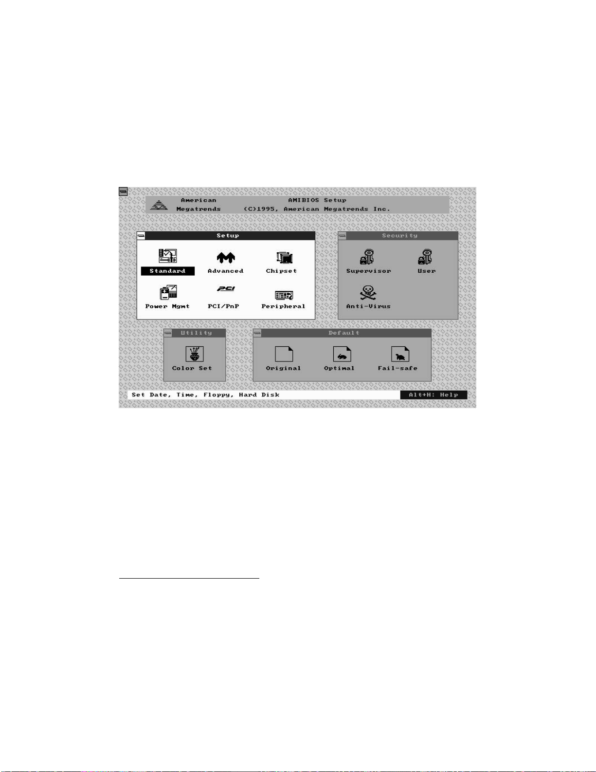
9.01.2 AMIBIOS SETUP MAIN MENU
The main menu screen looks as follows:
Four windows appear on the above screen:
• Setup window (explained in section 9.01.4)
• Security window (section 9.01.5)
• Utility window (section 9.01.6)
• Default window (section 9.01.7).
The Setup window is highlighted on the screen displayed above, meaning that you can
select items in that window. To highlight the other windows, press the TAB key on the
keyboard, or if a supported mouse1 was detected, move the arrow cursor over the desired
window, and click the left mouse button.
F Press TAB to select a window (Setup, Security, Utility, or Default) or click the
mouse inside that window.
1
All PS/2-type mice are supported, as well as bus mice that use IRQ 3, 4 or 5 (not
2), Microsoft-compatible mice (M, V, W Series), Logitech C-series-compatible
mice and many serial mice.
VIPer Software Setup 9-3
Page 73

9.01.3 MAKING SELECTIONS, SAVING CONFIGURATIONS &
EXITING AMIBIOS SETUP
MAKING SELECTIONS
Each of the windows displayed in the main menu screen contains icons (small drawings
under which an identifying label appears). For example, the Setup window has the
following icons and labels: Standard, Advanced, Chipset, Power Mgmt, PCI/PnP and
Peripheral. Each of these icons corresponds to various setups available within AMIBIOS
Setup, i.e. the Standard Setup, the Advanced Setup, the Chipset Setup, the Power
Management Setup, the PCI/PnP Setup and the Peripheral Setup. Selecting one of these
icons gives access to the corresponding Setup and its options.
To select an icon within a window, you must press one of the arrow keys on the keyboard
until the desired icon is highlighted, and then press the ENTER key, or move the mouse to
highlight the icon and click the left button to select. This method of selection basically
applies for all selectable items (icons, options, and settings).
F Icons, options and settings are selected by using one of the arrow keys to highlight
the desired item, then by pressing the ENTER key, or by clicking the mouse over
the desired selection.
The windows in the program have layers, like boxes inside boxes. Selecting an icon, may
display another window with icons; in turn, selecting one of these icons can display a
window which contains a list of options. Selecting an option will in turn open a window
containing a list of possible settings. To return to a previous window, you press the ESC
key on the keyboard, or click the small box on the top left corner of the window.
F To close the current window and move to the previous window, press the ESC key
or click the small box on the top left corner of the window.
Mostly all selections and settings will be done using the special keys (TAB, ESC, →, ←,
↑, ↓ and ENTER) or using the mouse’s left button. There are a few exceptions, for
example while entering the date and time (Standard Setup option), you need to use the +
or - keys or click the + or - boxes to change the values. Another example is when
characters need to be entered at the keyboard, such as a password (a window appears
which ressembles a keyboard; as you enter the characters, "*" is displayed for each
character entered; then to accept the password, press ENTER).
VIPer Software Setup 9-4
Page 74

SAVING CONFIGURATIONS & EXITING AMIBIOS SETUP
If you press the ESC key from the main menu screen or click the small box on the upper
left corner of one of the main menu windows, an EXIT SETUP window appears.
The EXIT SETUP window displays the following options:
• Save changes and Exit
• Do not save changes and Exit
• Continue
Each is explained below:
Save changes and Exit
After having modified the AMIBIOS Setup, you can save the configuration in CMOS
RAM, by selecting this option. After the information is saved, the computer is
automatically rebooted. This option will not change the default values saved in Boot-Block
Flash.
Do not save changes and Exit
This option is used to exit AMIBIOS Setup without saving the configuration to CMOS
RAM.
Continue
To return to the main menu without saving or exiting, select this option.
F To save changes and write the new configuration to CMOS RAM, select the "Save
changes and Exit" option from the EXIT SETUP window.
The four windows of the main menu, will now be described in the remainder of this
section.
VIPer Software Setup 9-5
Page 75

9.01.4 SETUP WINDOW
This section describes the six options of the Setup Window. These are:
• Standard Setup: offers the options to set the time, date, hard disk parameters, and
floppy drives.
• Advanced Setup: handles options and features such as key repetition settings, boot
sequence, NUM LOCK and password checking, shadowing, ...
• Chipset Setup: sets chipset-specific options and features.
• Power Management Setup: sets power conservation options.
• PCI/PnP Setup: sets the Plug and Play related options.
• Peripheral Setup: sets I/O controller-related options.
VIPer Software Setup 9-6
Page 76

STANDARD SETUP
This part of the setup allows you to set the time, date, hard disk type, types of floppy
drives, monitor type, and whether the keyboard is installed.
The Standard Setup screen displays seven icons as follows:
Pri Master Sec Master
Pri Slave Sec Slave
These four hard disk drive icons are for configuring hard disks connected to the VIPer808
or to a peripheral board. Select the appropriate hard disk drive icon (Pri Master = C:
drive).
For each hard disk, these options can be defined: TYPE, LBA/LARGE MODE, BLOCK
MODE, 32BIT MODE and PIO MODE. TYPE and PIO MODE can be Auto detected if
the hard disk drive is an IDE drive: the Auto option automatically finds all of the IDE
drive parameters for that hard disk. You should check your hard disk data sheets to know
if any of the other options - LBA/LARGE MODE, BLOCK MODE and 32BIT MODE should be set to ON; if your hard disk supports these modes, enabling them will optimize
your system.
F It is possible that the parameters provided by Auto detection do not match the
ones found in your drive's literature. This should not be considered an error. As
a matter of fact, different combinations of heads, cylinders and sectors that
match the disk's size will work when formatting an IDE hard drive. But if the
disk is already formatted, it is not possible to use different parameters than the
ones that were used when the drive was originally formatted.
Date/Time
The current values for each category are displayed. To change the date or time, highlight
the values you want to change, and press the + or - key or click the + or - box, until the
desired value is displayed.
Floppy A
Floppy B
The settings are: 360KB 5¼ inch, 1.2MB 5¼ inch, 720KB 3½ inch, 1.44MB 3½ inch,
2.88MB 3½ inch, or not installed.
VIPer Software Setup 9-7
Page 77

ADVANCED SETUP, CHIPSET SETUP, POWER MANAGEMENT SETUP, PCI/PNP
SETUP & PERIPHERAL SETUP
The Advanced Setup, Chipset Setup, Power Management Setup, PCI/PnP Setup and
Peripheral Setup are described in the following pages with both Fail-Safe Defaults and
Optimal Defaults values.
Whenever you are not sure about a certain setting, you may refer to the list of default
values. The list of defaults is provided in the event that a value has been changed and one
wishes to set this option to its original value. Loading the Optimal or Fail-Safe defaults
will affect all the options and will reset options previously altered.
The Fail-Safe default settings consist of the safest set of parameters. Use them if the
system is behaving erratically. They should always work but do not provide optimal
system performance.
The Optimal default values provide optimum performance settings for all devices and
system features.
These default values have been provided to give control over the system. However, the
values for these options should be changed only if the user has a full understanding of the
timing relationships involved.
VIPer Software Setup 9-8
Page 78

TABLE 9-1: Advanced Setup
Option Fail-safe Defaults Optimal Defaults Possible Settings Description
Quick Boot Disabled Enabled Enabled, Disabled This option allows AMIBIOS to boot faster than usual (from power on to adaptor ROM initialization in less than five seconds). It also
Boot Up Sequence A:, C:, CDROM C:, A:, CDROM C:, A:, CDROM
A:, C:, CDROM
CDROM, C:, A:
Boot CPU Speed Low High Low, High This option sets the speed at which the system boots.
Boot Up Num-Lock On On On, Off
Floppy Drive Swap Disabled Disabled Enabled, Disabled
Floppy Drive Seek Enabled Disabled Enabled, Disabled This option, when enabled, specifies that a SEEK instruction will be performed on the floppy drive A: at system boot time.
Mouse Support Disabled Enabled Enabled, Disabled When enabled, this option specifies that a PS/2 mouse is supported.
Typematic Rate Fast Fast Slow, Fast This option sets the rate at which characters displayed on the screen repeat, when a key is pressed and held down.
Primary Display VGA/EGA VGA/EGA VGA/EGA, CGA 40x25, CGA 80x25,
Password Check Setup Setup Always, Setup
Parity Check Disabled Disabled Enabled, Disabled This option enables or disables parity error checking for system memory (DRAM).
OS/2 Compatible Mode Disabled Disabled Enabled, Disabled When there is more than 16MB system memory and you wish to boot with OS2 operating system, you must set this option to Enabled.
Wait for “F1” If Error Enabled Disabled Enabled, Disabled When this option is Enabled, a failure during boot-up automatically displays an error with the message “RUN SETUP UTILITY Press
Hit “DEL” Message Display Enabled Enabled Enabled, Disabled
Internal Cache Disabled WriteThru
or Write Back
(CPU dependant)
Video Shadow C000, 32K Enabled Enabled Enabled, Disabled When this option is set to Enabled, the video BIOS ROM area at the specified address is copied (shadowed) from ROM to RAM for
Shadow C800, 16K Disabled Disabled Enabled, Disabled These options enable shadowing of the contents of the ROM area beginning at the address named in the option title. For example, the
Shadow CC00, 16K Disabled Disabled Enabled, Disabled
Shadow D000, 16K Disabled Disabled Enabled, Disabled
Shadow D400, 16K Disabled Disabled Enabled, Disabled
Shadow D800, 16K Disabled Disabled Enabled, Disabled
Shadow DC00, 16K Disabled Disabled Enabled, Disabled
WriteThru, WriteBack (only available if
supported by the CPU), Disabled
MONO
supports the Instant On features as specified in the Intel power management specifications. When Quick Boot is enabled, AMIBIOS
does not test memory above 1MB and does not wait up to 40 seconds for a READY signal from the IDE hard drive (as a result,
AMIBIOS does not configure that drive if a READY signal is not received immediately).
This option specifies the boot sequence for drive A:, C:, CDROM after AMIBIOS POST completes and attempts to boot DOS. When
booting from the CDROM drive, the CDROM behaves like drive A: if it has a floppy boot image. The CDROM drive now becomes drive
A: and the first floppy drive becomes drive B:. On the other hand, the CDROM behaves like a hard drive if the CDROM has a hard disk
boot image. The CDROM drive now becomes drive C: and all other hard drives are shifted one letter (the hard disk drive becomes drive
D:).
If this option is set to Off, the NUM LOCK key on the keyboard is turned off when the system is powered on; you can use the →, ←, ↑,
↓ keys on both the numeric keypad and the keyboard.
By enabling this option, floppy drive A: becomes drive B:, and drive B: (if present) becomes drive A:. Thus you are allowed to boot from
drive B:.
This option specifies the type of display adapter card installed in the system.
This option enables a password check every time the system boots of if AMIBIOS Setup is executed. If always is chosen, a user
password prompt appears every time the computer is turned on. If Setup is chosen, the password prompt appears if AMIBIOS is
executed. The password feature is disabled by default but can be enabled by using the SUPERVISOR and USER options (SECURITY
window) for the first time.
F1 to RESUME”; pressing the F1 key runs the AMIBIOS Setup Program, so that the Setup can be updated.
Disabling this option prevents the “Hit<DEL> if you want to run Setup” message from appearing when the system boots.
This option enables or disables the CPU Internal Cache Memory. WriteBack Cache provides better performance than WriteThru
Cache. Some CPUs support only WriteThru Cache, while others support WriteBack and WriteThru Cache.
faster execution.
C800, 16K SHADOW option enables shadowing of the contents of ROM from C8000h-CBFFFh to RAM.
Not all BIOS can be shadowed. In some cases, it can result in erratic operation. For example, if the expansion board has
built-in “scratchpad memory”, which is used internally, shadowing may cause unpredictable results.
VIPer Software Setup 9-9
Page 79
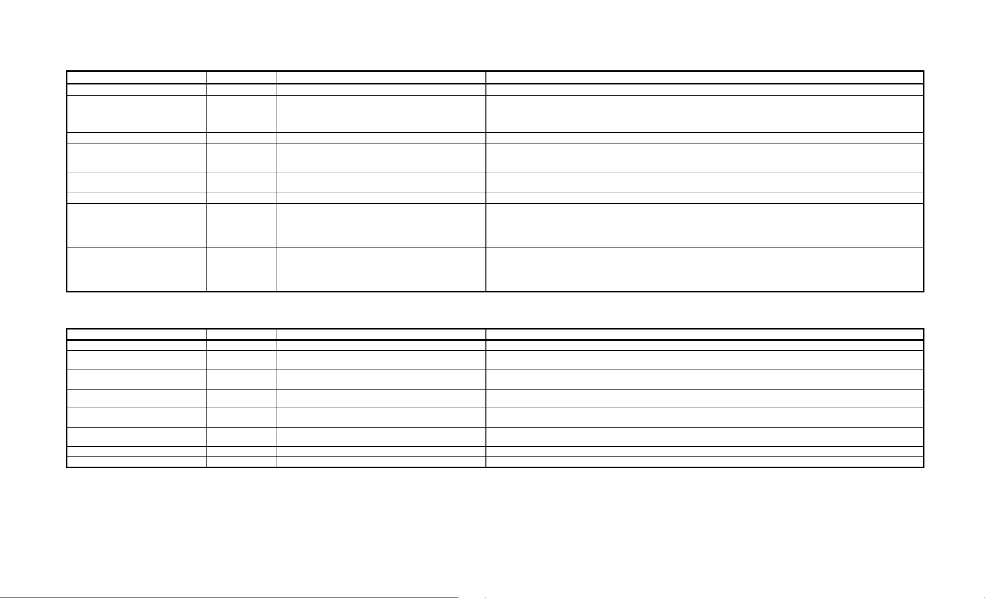
TABLE 9-2: Chipset Setup
Option Fail-safe Defaults Optimal Defaults Possible Settings Description
DRAM Wait State 2 wait 1 wait 1 wait, 2 wait This option allows the selection of a wait state for DRAM reads and writes.
SYSCLK Divisor Select Auto Auto Auto,
CLOCK2IN/2, CLOCK2IN/3,
CLOCK2IN/4, CLOCK2IN/5,
CLOCK2IN/6, CLOCK2IN/8
AT Ready Delay Selects 2HS1XCLK No Delay No Delay, 1HS1XCLK, 2HS1XCLK Sets the number of SYSCLK wait states to add, after a ready is received on the AT bus.
Back to Back I/O Delay 3 SYSCLK 0 SYSCLK 0 SYSCLK, 1 SYSCLK,
2 SYSCLK, 3 SYSCLK
ISA Refresh Enabled Disabled Enabled, Disabled This option enables the refresh cycle on the ISA bus. Some ISA peripheral boards use the ISA Refresh signal (for example, bus
Turbo IDE Function Disabled Enabled Enabled, Disabled This option enables the Local Bus IDE.
Turbo IDE Command Width 9HS1XCLK 9HS1XCLK 2HS1XCLK, 3HS1XCLK,
4HS1XCLK, 5HS1XCLK,
6HS1XCLK, 7HS1XCLK
8HS1XCLK, 9HS1XCLK
Turbo IDE Back to Back Delay 16HS1XCL 16HS1XCL 2HS1XCLK, 4HS1XCLK,
6HS1XCLK, 8HS1XCLK,
10HS1XCLK, 12HS1XCLK
14HS1XCLK, 16HS1XCLK
Sets the speed of the ISA bus clock (SYSCLK) signal, which must be set to approximately 8MHz. The appropriate divisor depends on
the CPU external bus speed.
Sets the delay, in terms of ISA bus clock, between consecutive ISA bus I/O cycles. This option is used for older ISA devices which
require longer delays between consecutive I/O cycles. Due to the higher speed of new processors, it may be necessary to add the Back
to Back I/O Delay for these older adaptor card.
mouse).
Sets the pulse width of read and write accesses from and to the hard drisk. HS1XCLK is the same speed as the CPU bus clock. The
minimum required pulse width varies from drive to drive. Consult your hard disk specifications for minimum pulse width.
Sets the delay between hard disk accesses. HS1XCLK is the same speed as the bus clock. The minimum required delay varies from
drive to drive.Consult your hard disk specifications for minimum delay.
TABLE 9-3: Power Management Setup
Option Fail-safe Defaults Optimal Defaults Possible Settings Description
Power Management /APM Disabled Disabled Enabled, Disabled When Enabled, activates power saving modes: DOZE, SLEEP and SUSPEND.
DOZE Mode Time Out Disabled 4 sec. Disabled,
1, 4, 8. and 16 sec.
SLEEP Mode Time Out Disabled 1 min. Disabled, 1, 2, 4, 6,
8, 12, and 16 min.
Hard Disk Time Out Disabled Disabled Disabled, 1, 2, 3, 4, 5, 6, 7 min. This option enables a non-activity timeout, after which the hard disk is put into Standby mode. Note that once the hard disk has
Video Standby Time Out Disabled Disabled Disabled, 5, 10, 15
30, 45, 60, 90 sec.
SUSPEND Time Out Disabled 5 min. Disabled, 5, 10, 15
20, 30, 40 and 60 min.
Resume with Modem Ring Disabled Disabled Disabled, 1, 2 and 4 Rings Enables and specifies the number of modem rings required to re-activate the CPU when in Suspend Mode
Suspend Warning Beeps Enabled Enabled Enabled, Disabled When Enabled, warning beeps will be sounded before entering Suspend Mode.
This option sets the time-out period to enter into Doze Mode when inactivity is detected.
This option sets the time-out period to enter into Sleep Mode from Doze Mode.
entered Standby mode, the next hard disk access will take a few extra seconds to occur.
This option enables a non-activity timeout, after which a video display is put into Standby mode. Any subsequent detected activity will
reenable the display.
This option sets the time-out period to enter into Suspend Mode from Sleep Mode.
VIPer Software Setup 9-11
Page 80
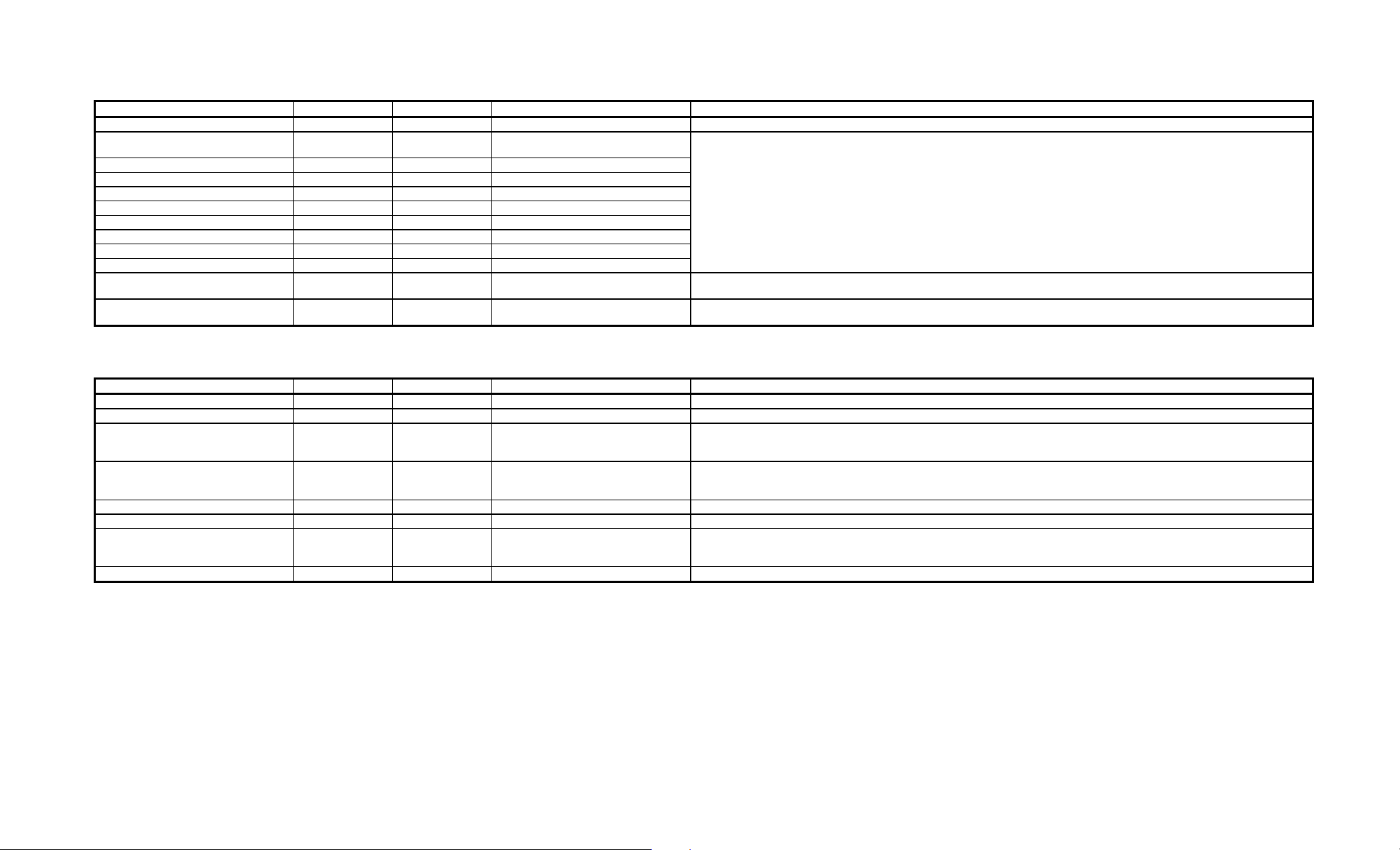
TABLE 9-4: PCI/PnP Setup
Option Fail-safe Defaults Optimal Defaults Possible Settings Description
Plug and Play Aware O/S Yes Yes Yes, No This option allows AMIBIOS to know if the operating system installed in the computer is Plug and Play-aware.
IRQ3 PnP PnP PnP, ISA/EISA This option indicates which the bus is used by the IRQ and allows you to specify IRQs for use by legacy ISA adapter cards. To remove
IRQ4 PnP PnP PnP, ISA/EISA
IRQ5 PnP PnP PnP, ISA/EISA
IRQ7 PnP PnP PnP, ISA/EISA
IRQ9 PnP PnP PnP, ISA/EISA
IRQ10 PnP PnP PnP, ISA/EISA
IRQ11 PnP PnP PnP, ISA/EISA
IRQ14 PnP PnP PnP, ISA/EISA
IRQ15 PnP PnP PnP, ISA/EISA
Reserved Memory Size Disabled Disabled Disabled, 16K, 32K, 64K This option sets the size of the memory area reserved for legacy ISA adapter cards (this area cannot be used by PnP ISA adapter
Reserved Memory Address C8000 C8000 C0000, C4000, C8000, CC000, D0000,
D4000, D8000, DC000
IRQs from the pool of available IRQs passed to BIOS configurable devices, set this option to ISA/EISA.
cards).
This option indicates the beginning address (in hex) of the reserved memory area. This memory area (part of ROM memory) is reserved
for use by legacy ISA adapter cards.
TABLE 9-5: Peripheral Setup
Option Fail-safe Defaults Optimal Defaults Possible Settings Description
OnBoard IDE Primary Primary Primary, Secondary, Disabled This option enables the use of the onboard IDE Controller.
OnBoard FDC Enabled Auto Enabled, Disabled, Auto This option enables the use of the onboard Floppy Drive Controller.
OnBoard Serial Port 1 3F8h Auto Auto, Disabled, 3F8h, 2F8h, 3E8h,
2E8h (if one of these addresses is used
by Serial Port 2, it is not available)
OnBoard Serial Port 2 2F8h Auto Auto, Disabled, 3F8h, 2F8h, 3E8h,
2E8h (if one of these addresses is used
by Serial Port 1, it is not available)
OnBoard Parallel Port 378h Auto Auto, Disabled, 378h, 278h, 3BCh This option enables the Parallel Port.
Parallel Port IRQ 7 Auto Auto, IRQ5, IRQ7 This option defines which IRQ line is to be used for the Parallel Port.
Parallel Port Mode Normal ECP Norma, Bi-Dir (bi-directional), EPP
(Enhanced Parallel Port), ECP
(Extended Capabilities Port)
Parallel Port DMA Channel None Auto Auto, None, 0, 1, 2, 3 This option defines which DMA channel will be used for the Parallel Port’s ECP mode.
This option enables Serial Port 1.
This option enables Serial Port 2.
This option specifies the Parallel Port Mode.
VIPer Software Setup 9-13
Page 81

9.01.5 SECURITY WINDOW
When the Supervisor or User icon is selected from the Security window in the main menu,
the user can enable the password feature or change the password itself. By default, the
user can boot the system and enter the AMIBIOS Setup without any restrictions. Choosing
a password for the first time will automatically enable the password feature. At the next
bootup, the user will be prompted to enter his password on bootup or when he attempts to
enter AMIBIOS Setup, depending on the setting of the PASSWORD CHECK option in
the ADVANCED SETUP (see the PASSWORD CHECK option description for the
available settings).
F To disable the password, use this option: 1) At the prompt "Enter CURRENT
Password", enter your password, 2) Then at the prompt "Enter NEW Password",
press ENTER, 3) Then at the prompt "Confirm NEW Password", press ENTER,
4) The screen then displays "Password uninstalled". Make sure you select Save
Changes and Exit from the EXIT SETUP window. If you forget your current
password, the password feature can be disabled by removing jumper W22 for
several minutes; however this will also clear the CMOS Setup, which will then be
configured at the BIOS default values.
SUPERVISOR
This option allows you to enable the main password of the supervisor user. You must set a
supervisor password before attempting to set user passwords. If you disable this password,
all user passwords will automatically be disabled as well.
USER
This option allows you to enable and disable a password for each user. A supervisor
password must be set before attempting to set user passwords.
ANTI-VIRUS
This option allows you to enable and disable anti-virus protection for the hard disk boot
sector.
VIPer Software Setup 9-15
Page 82

9.01.6 UTILITY WINDOW
COLOR SET
If you select Color Set, it allows you to set up the background/foreground colors of the
screen. The settings are: LCD, Army, Pastel, and Sky.
VIPer Software Setup 9-16
Page 83

9.01.7 DEFAULT WINDOW
The Default window of the main menu has three options available for automatically
reconfiguring the AMIBIOS Setup (the settings are loaded in the program and displayed
in their respective fields, but they are not saved in CMOS):
• Original: This option allows you to reset all options to the values which were last
saved in the CMOS Setup; it will be used to restore the values saved in
CMOS, after a number of settings have been changed in the AMIBIOS
Setup program.
• Optimal: This option allows you to load the Optimal Default values. These are
common recommended values and should optimize system performance.
This feature might be useful in instances where a quick reconfiguration is
needed.
• Fail-Safe: This option allows you to load the Fail-Safe Default settings. These are
worst-case values that are the most stable values that can be chosen. Use
this option as a diagnostic aid if the system is behaving erratically.
VIPer Software Setup 9-17
Page 84

9.02 UPDATING OR RESTORING BIOS IN BOOT-BLOCK FLASH
The Boot-Block Flash device contains a non-erasable boot-strap loader which can
reprogram the device with a BIOS file from a floppy drive diskette.
All VIPer808 BIOSes are stored in the file SEQ256.BIN in the Boot-Block Flash device.
For the Main BIOS (AMIBIOS), only the default values are stored (fail-safe and optimal)
in Boot-Block Flash; therefore if changes are made to the settings, these will not be saved
in the Boot-Block Flash BIOS file.
If you need to update or restore the VIPer808 BIOS file SEQ256.BIN in the Boot-Block
Flash, follow this procedure:
1. Turn off your computer system.
2. Place diskette with SEQ256.BIN file in drive A. Make sure the SEQ256.BIN file is on
the diskette.
3. Hold the CTRL and HOME keys simultaneously and power on your computer system.
Release the CTRL-HOME keys after a few seconds.
4. After the three audible beeps, remove diskette from drive A. Boot-up will proceed.
The Boot-Block Flash BIOS is now updated or restored.
VIPer Software Setup 9-18
Page 85

APPENDICES
APPENDIX A: VIPer808 SPECIFICATIONS
APPENDIX B: MEMORY & I/O MAPS
APPENDIX C: MECHANICAL LAYOUT & BLOCK DIAGRAM
APPENDIX D: CONNECTOR PINOUTS
APPENDIX E: RECOMMENDED DEVICES & MATING CONNECTORS
APPENDIX F: ERROR CODES
Page 86

APPENDIX A
VIPer808 SPECIFICATIONS
A.01 SPECIFICATIONS
Operating Temperature: The maximum operating ambient temperature
of the board is limited by the temperature of the
CPU itself, as shown on Table A-1.
TABLE A-1: Maximum Operating Temperature (°C)
Processor Heatsink Frequency
(MHz)
0 200 400 600
Intel
486DX Yes 33 50 65 71 74
486DX No 33 38 46 52 59
486DX2 Yes 66 19 48 59 65
486DX2 No 66 -4 11 22 36
486DX4 Yes 100 35.5 57 65.5 70
486DX4 No 100 18.5 29 37.5 44
AMD
5X86 Yes 133 54.3 69.6 75.8 78.9
5X86 No 133 37.4 46.6 52.7 57.3
SGS
486DX4 Yes 100 57 65 70 72
486DX4 No 100 47 57 62 65
Airflow - feet / minute
Noncondensing Relative Humidity: 5% to 95%
Electrical: Conforms to the IEEE P996 PC/AT bus
electrical specifications
Supply Voltage: + 5V ±5%
VIPer808 Specifications A-1
Page 87

Supply Current:
TABLE A-2: Supply Current
SUPPLY CURRENT*
ICC Typical (+5V) 1.4A 1.8A 1.9A 1.1A 1.4A 1.5A
DOZE Mode n/a 0.7A 0.7A 0.6A 0.6A 0.7A
SLEEP Mode n/a 0.6A 0.7A 0.5A 0.5A 0.6A
SUSPEND Mode n/a 0.4A 0.4A 0.4A 0.4A 0.4A
Intel
DX-33
Intel
DX2-66
Intel
DX4-100
AMD
DX2-66
AMD
DX4-100
AMD
5x86-133
* Measured with 4 MB System Memory, 1 MB Video Memory and no CPU Fan.
Mechanical: • Conforms to the IEEE P996 PC/AT bus
mechanical specifications.
• 7.125 in. x 4.8 in. / 181mm x 122mm.
VIPer808 Specifications A-2
Page 88

A.02 BATTERY
The VIPer808 comes with a 360mAh TL5186 TADIRAN battery. It powers the System
Controller’s Real Time Clock and CMOS Setup, whenever the board is powered down.
The TADIRAN TL5186 has a shelf life of approximately 10 years (under "no-load"
conditions). The actual life of the battery depends on environmental (temperature)
conditions. The TADIRAN TL5186 has an operating range of -55o to 75°C and discharge
characteristics vary with temperature.
The voltage supplied by the battery is 3.6 volts. This can be verified with a standard
voltmeter at the battery socket’s two extreme pins (if you use the pin on the soldered side,
you do not have to remove the battery).
The TADIRAN TL5186 is UL recognized. Its UL component recognition is MH12193.
Jumper W22 enables the Internal Battery’s power. Removing the W22 jumper has the
same effect as putting the battery in storage; TEKNOR always ships its board with battery
jumper removed in order to increase the life of the battery.
An External Battery may be used. In such a case, pins 2 and 3 of jumper W22 should be
shorted.
Please refer to Section 3 for jumper location and setting.
VIPer808 Specifications A-3
Page 89

A.03 MTBF (MEAN TIME BETWEEN FAILURES)
The reliability analysis performed on the VIPer808 reflects all available options and has
resulted in the following predicted reliability:
TABLE A-3: Reliability Prediction
Board
Configuration
Video Memory 512KB 1MB 512KB 1MB 512KB 1MB
CPU Type
486DX33 5V
(INTEL)
486DX2-66 5V
(INTEL)
486DX4-100 3.3V
(INTEL)
486DX2-66 3.45V
(AMD)
486DX4-100 3.45V
(AMD)
5X86-133 3.45V
(AMD)
Basic Board Ethernet Interface
MTBF (hour) /
Failure Rate (x10-6)
140570
7.1139
125359
7.9771
137515
7.2719
160330
6.2371
150551
6.6423
134686
7.4247
139169
7.1855
124243
8.0487
136174
7.3435
158510
6.3087
148945
6.7139
133399
7.4963
10Base 2
MTBF (hour) /
Failure Rate (x10-6)
130121
7.6851
116982
8.5484
127499
7.8432
146878
6.8084
138629
7.2135
125064
7.9959
128920
7.7567
116010
8.6200
126346
7.9148
145349
6.8800
137266
7.2851
123954
8.0675
Ethernet Interface
10Base-T
MTBF (hour) /
Failure Rate (x10-6)
132655
7.5384
119025
8.4016
129931
7.6964
150114
6.6616
141508
7.0667
127402
7.8491
131407
7.6100
118020
8.4732
128733
7.7680
148518
6.7332
140089
7.1383
126251
7.9207
The MTBF is estimated using the prediction data from MIL-HDBK-217F, Reliability
Prediction of Electronic Equipment (Dec. 1991).
The VIPer808 board is considered functioning in a Ground Fixed environment as defined
in MIL-HDBK-217F. The calculations are performed at 20°C with a temperature rise of
10°C which is due to heat dissipated by active components.
It is assumed that only one failure at a time can occur and that the failure of any
component will result in the system becoming inoperative or, as a minimum, resulting in
a degraded mode of operation requiring repair action. All components are considered as
having an exponential distribution of time to failure, with a constant failure rate. A failure
rate is attributed to each component called in the parts list, according to the stress levels it
is submitted during normal operation.
VIPer808 Specifications A-4
Page 90

The components with the highest calculated failure rate in the VIPer808 reliability
prediction are: the 486 CPU, the SVGA (GD5429), the Sequoia chip set (PT86C718) and
the chip set (PT86C768).
The quality factors for commercial components on the VIPer808 has been adjusted in
order to represent the impact of burn-in. TEKNOR submits each processor board produced
to a 12 hour burn-in at 40°C. The boards are powered during this phase to precipitate
latent failures. It is well known that a burn-in performed under these conditions improves
board and component quality. Since there is a correlation between quality and reliability,
it is generally accepted in the industry to reflect this in the reliability prediction.
VIPer808 Specifications A-5
Page 91

A.04 MEETING INDUSTRY STANDARDS
TEKNOR Quality Standards insist that our products meet or exceed industry standards set
by such respected agencies, organizations and associations as UL and CSA.
As a result, the VIPer808 has the following built-in features to help ensure that the
conditions required for approval are met:
• A current block diode on the battery circuit,
• A current limiter resistor on the battery,
• A protection fuse on the keyboard controller.
TEKNOR computer cards are designed to meet industry standards for customers requiring
approval for their equipment.
VIPer808 Specifications A-6
Page 92
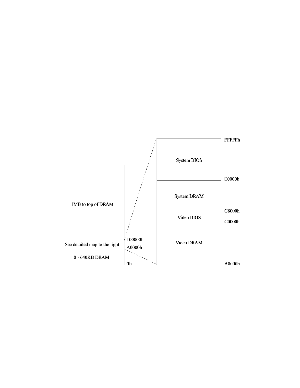
APPENDIX B
MEMORY & I/O MAPS
B.01 MEMORY MAPS
DIAGRAM B-1: Memory Map Diagram
Memory & I/O Maps B-1
Page 93

Table B-1 displays the memory map in a table format.
TABLE B-1: Memory Map
Address Optional Address Function
00000-0FFFF 0-640 KB DRAM
A0000-BFFFF Video DRAM
C0000-C7FFF Video BIOS
C8000- DFFFF System DRAM
E0000-FFFFF System BIOS
100000 - Top of DRAM 1MB - Top of DRAM
Memory & I/O Maps B-2
Page 94

B.02 I/O MAP
TABLE B-2: I/O Map
Address Optional
Address
000-00F DMA Controller 1
024, 026 Chipset Configuration
020-03F Interrupt Controller 1
040-043 Counter/Timers
060-064 Keyboard (8742)
070-071 Real-time clock,
080-09F DMA Page Register
0A0-0BF Interrupt Controller 2
0C0-0DF DMA Controller 2
0F0-0FF Math Coprocessor
1F0-1F7, 3F6-3F7 IDE Hard Disk
300-317 320-337 340-357 See Note 1 Ethernet Port
3F0-3F7 370-377 Floppy Disk
378-37A 3BC-3BE 278-27A Parallel Port
Optional
Address
Optional
Address
Function
Registers
NMI mask
(LPT1 by default)
3F8-3FF (COM1) 2F8-2FF
(COM2)
2F8-2FF (COM2) 3F8-3FF
(COM1)
3C0-3CF, 3D0-3DF,
3B0-3BB, 46E8h
3E8-3EF
(COM3)
3E8-3EF
(COM3)
2E8-2EF
(COM4)
2E8-2EF
(COM4)
UART1
(COM1 by default)
UART2
(COM2 by default)
Graphics Controller
Note 1: Other address ranges: 360-377, 380-397, 3A0-3B7, 3C0-3D7 and 3E0-3F7.
Note 2: In the function “Graphics Controller”, 46E8h is the address for Sleep Mode.
Memory & I/O Maps B-3
Page 95

APPENDIX C
MECHANICAL LAYOUT & BLOCK DIAGRAM
In this appendix, two diagrams are included in the following pages.
DIAGRAM C-1: Mechanical Specifications
DIAGRAM C-2: Block Diagram VIPer808
Mechanical Layout & Block Diagram C-1
Page 96
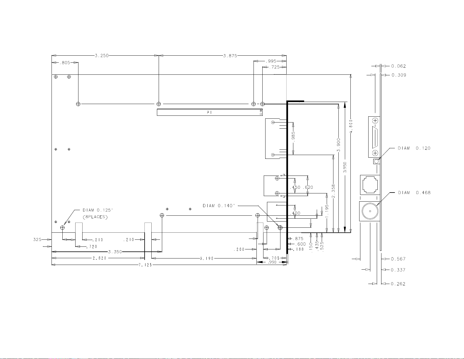
DIAGRAM C-1: Mechanical Specifications
Mechanical Layout & Block Diagram C-3
Page 97
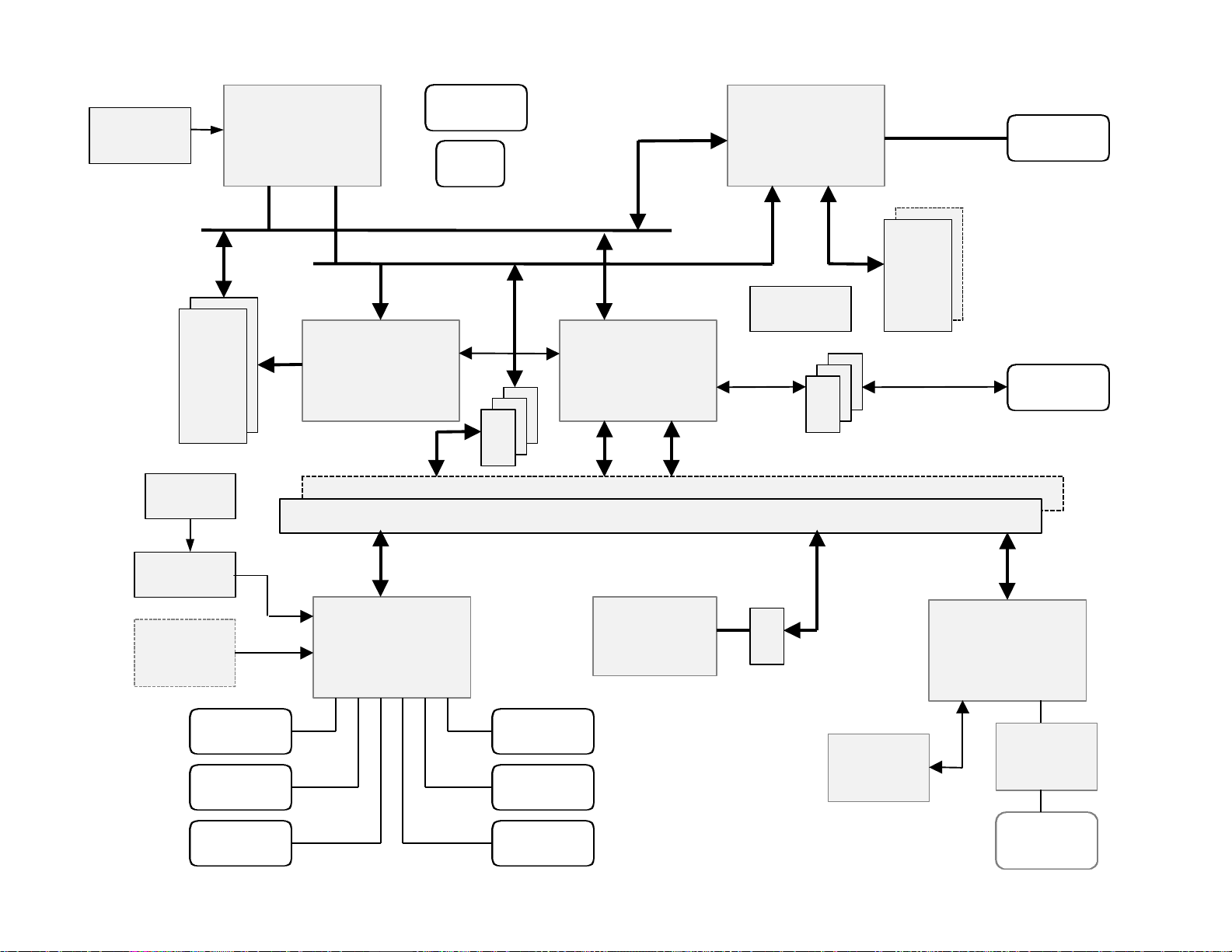
DIAGRAM C-2: Block Diagram VIPer808
5V-3.4V
DC-DC CONV.
BATTERY
DRAM
SIMMS
UP TO
128MB
3.6V
CPU
486DX2/DX4
5x86
CONTROLLER
Local Bus D[0:31]
Local Bus A[2:31]
PICO/POWER
SEQUOIA_1
SYSTEM
SA
EXT. POWER
CONNECTOR
5V FAN
CONN.
J11
245
J9
PICO/POWER
SEQUOIA_2
SYSTEM
CONTROLLER
SD
CTRL
PC104 8/16 BIT (OPTION)
ISA BUS; PC/AT BUS
CIRRUS
CL_GD5429
CRT SVGA
CONTROLLER
CLOCK
GENERATOR
245
VIDEO
DRAM
512K/
1MByte
SVGA
CONNECTOR
J1
IDE HD
CONNECTOR
J12
SUPERVISOR
MAX 691
93C56
SERIAL
EEPROM
CONNECTOR
CONNECTOR
KBD/SPKR
CONNECTOR
COM1
COM2
CONTROLLER
J7
J4
SMC
FDC37C932
ULTRA I/O
J13
PRINTER
PAR. PORT
J2
FLOPPY
CONNECTOR
J10J3
PS/2 MOUSE
CONNECTOR
BIOS
BOOT-BLOCK
FLASH (2M)
SD
245
AMD
Am79C961
ETHERNET
CONTROLLER
93C56
SERIAL
EEPROM
J14 / J15
10BASE-T/
10BASE-2
INTERFACE
RJ45/BNC
CONNECTOR
Mechanical Layout & Block Diagram C-5
Page 98

APPENDIX D
CONNECTOR PINOUTS
IDE Hard Disk Connector (J1) - Pinout
Pin
Number
1
3
5
7
9
11
13
15
17
19
21
23
25
27
29
31
33
35
37
39
Signal
Flow
I
I/O
I/O
I/O
I/O
I/O
I/O
I/O
I/O
-
I
I
O
O
I
I
I
O
* Active low signal
Signal Pin
RESET*
HD7
HD6
HD5
HD4
HD3
HD2
HD1
HD0
GND
Not Connected
IOW*
IOR*
IOCHRDY
Not Connected
IRQ14
SA1
SA0
CS0*
ACTIVE*
Number
2
4
6
8
10
12
14
16
18
20
22
24
26
28
30
32
34
36
38
40
Signal
Flow
I/O
I/O
I/O
I/O
I/O
I/O
I/O
I/O
-
-
-
I
O
I
I
-
Signal
GND
HD8
HD9
HD10
HD11
HD12
HD13
HD14
HD15
Not Connected
GND
GND
GND
BALE
GND
IOCS16*
Not Connected
SA2
CS1*
GND
Connector Pinouts D-1
Page 99

Floppy Connector (J2) - Pinout
Pin
Number
1
3
5
7
9
11
13
15
17
19
21
23
25
27
29
31
33
Signal
Flow
-
-
-
-
-
-
-
-
-
-
-
-
-
-
-
-
-
* Active low signal
Signal Pin Number Signal
GND
GND
GND
GND
GND
GND
GND
GND
Not Connected
GND
GND
GND
GND
Not Connected
Not Connected
GND
Not Connected
2
4
6
8
10
12
14
16
18
20
22
24
26
28
30
32
34
Flow
O
-
I
O
O
O
O
O
O
O
O
I
I
I
O
I
Signal
DRV DENS.SEL.0*
Not Connected
Not Connected
INDEX*
MOTOR ON 0,1*
DRIVE SELECT B*
DRIVE SELECT A*
MOTOR ON 2*
DIR CONTROL*
STEP*
WRITE DATA*
WRITE ENABLE*
TRACK0*
WRITE PROTECT*
READ DATA*
HEAD SELECT*
DSKCHG*
Connector Pinouts D-2
Page 100

Keyboard / Speaker Connector (J3) - Pinout
Pin Number Pin Number
Signal Flow Signal Flow
Signal Signal
KBCLK I/O 1 2 - GND
KBDATA I/O 3 4 - GND
VCC (+5V) - 5 6 - VCC (+5V)
SPKR O 7 8 - VCC (+5V)
KBDINH I 9 10 - GND
Not Connected I 11 12 - GND
PBRES* I 13 14 - GND
HDD ACTIVE O 15 16 - VCC (+5V)
* Active low signal
Connector Pinouts D-3
 Loading...