

Page 1

TEK-AT3
80386DX SINGLE-BOARD COMPUTER
HARDWARE REFERENCE MANUAL
VERSION 1.1, February 1992
TEKNOR MICROSYSTEMS INC.
31 de la Seigneurie E.
Suite 107
Blainville, PQ
J7C 4G6 CANADA
NOTE
This manual is for reference purposes only.
Reproduction in whole or in part is authorized provided
TEKNOR MICROSYSTEMS INC. is cited as the
original source.
Page 2

FOREWORD
The information in this document is provided for
reference purposes only. Teknor does not assume any
liability for application or use of the information or
products described herein.
This document may contain or reference information
and products protected by the copyrights or patents of
others and does not convey any license under the patent
right of Teknor, nor the rights of others.
This manual does not discuss standard features of the
IBM family of Personal Computers. Instead, it focuses
on the superset of features that TEKNOR has
implemented into its single board computers.
For information on IBM standard features, please refer
to the following books available at your local book
stores:
- IBM AT Technical Reference Manual
- DOS Technical Reference
- Peter Norton's Programming The IBM PC
Page 3

This is by no means an exhaustive list. Many titles
exist on these subjects and just as many titles deal with
specialized applications such as extended memory
transfers, disk drives, ems, and so on.
If you require information not covered in this manual or
in our Application Notes releases, contact our Technical
Support/Services Department at (514) 437-5682.
Printed in Canada. Copyright 1992 by Teknor Microsystems Inc,
Blainville, Qc, J7C 4G6
Page 4

TABLE OF CONTENTS
SECTION 1: INTRODUCTION 1
SECTION 2: INSTALLATION
3
Unpacking 3
Multi-Configurations 3
PC/AT Passive Backplane 4
Stand-Alone 4
Keyboard 5
COM1 And COM2 Serial Channels 5
Printer Port 5
Reset, Speaker, Keyboard And
Keylock Interface 5
3.5" And 5.25" Floppy Disk Installation 6
Hard Disk Installation 6
System Memory Installation 6
Semiconductor-Disks 6
2-1 Configuration Overview 7
2-1-1 Setup Utility 7
2-1-2 Jumper Configuration Overview 8
2-2 Jumper Locations 11
2-2-1 TEK753 Flash EPROM
Board (Jumper Locations) 12
SECTION 3: MEMORY 13
3-1 Memory Mapping 13
3-2 Shadow RAM 13
Page 5

3-3 Expanded Memory System 13
3-4 Cache Memory 14
Page 6

SECTION 4: I/O MAP 17
4-1 Onboard Decoded I/O Map 17
SECTION 5: ONBOARD UTILITIES 19
5-1 DMA Controller (8237) 19
5-2 Interrupt Controller (8259) 19
5-2-1 Interrupt Register Addresses 19
5-3 Timer (8254) 19
5-4 Keyboard 20
5-4-1 Keyboard Controller 21
5-5 Supervisor Utilities 22
5-5-1 Watchdog Timer 22
5-5-1-1 Watchdog Timer Register 23
5-5-1-2 Hardware Configuration 23
5-5-2 Power Failure Detector 23
5-6 Real-Time Clock 25
5-7 Parallel Port (LPT1) 26
5-8 Serial Communications Port 26
5-8-1 COM1 (J6) Hardware
Configuration 27
5-8-2 COM2 (J4) Hardware
Configuration 28
Page 7

5-8-2-1 COM2 (J4) as RS232 28
5-8-2-2 COM2 (J4) as RS485 29
5-8-2-2-1 Full Duplex Operation 29
5-8-2-2-2 Party Line Operation 29
5-9 Floppy Disk Controller 30
5-9-1 3.5" And 5.25" Floppy Disk 31
5-10 Hard Disk Controller 32
5-10-1 Hard Disk Installation 32
5-10-2 Pin Out of Hard Disk
Interface Connector 33
5-11 Solid State Disks 34
5-11-1 Installation 35
5-11-1-1 User Configuration 35
5-11-2 Battery Back-Up 36
SECTION 6: OPERATION 39
6-1 Configuration Jumpers (SW1) 39
6-2 Logical Disk Configuration 39
6-3 VT100 Operation (SW(5-6)) 42
6-3-1 Requirements 42
6-3-2 Hardware Setup And
Configuration 42
Page 8

6-3-3 Running Without A Terminal 43
6-3-4 Disk Drives And Semi
Conductor Disks 46
6-3-5 Baud Rate Restrictions 46
6-4 Graphics/Stand-Alone (SW1(5-6)) 46
SECTION 7: TEK-AT3 BIOS 47
7-1 Overview And Features 47
7-2 Error Handling 47
SECTION 8: SPECIFICATIONS 49
8-1 DC Characteristics 49
8-2 Environmental Specifications 49
8-3 Mechanical Specifications 50
8-4 Assembly 51
8-5 Block Diagram 52
8-6 Connector Overview 53
8-6-1 J5 Power Connector 53
8-6-2 J3 Keyboard Connector 53
8-6-3 J7 Printer Connector 54
8-6-4 J6 COM1 Connector 55
8-6-5 J4 COM2 Connector RS232 55
8-6-6 J4 COM2 Connector RS485 56
Page 9

SECTION 9: LIMITED WARRANTY 57
Returning Defective Merchandise 57
SECTION 10: GETTING HELP 59
Need More Help? 59
APPENDICES
Appendix A i
Page 10

INTRODUCTION 1
INTRODUCTION SECTION 1
The TEK-AT3 provides users with a high performance
PC/AT type computer on a half-card format (7" x 4.7"),
integrating all the basic functions available on an IBM
AT. Including a hard disk interface and a floppy disk
controller. Best of all, the TEK-AT3 is designed to
operate in environments where a sturdy and compact
system is essential. So elements such as a watchdog
timer, solid state disks, and a power failure detector
were added to make the TEK-AT3 perform even in the
most extreme industrial applications.
Built using CMOS technology, the TEK-AT3 consumes
very little power. Typically, less than 7.5 watts. The
TEK-AT3 is also a versatile board. It can be installed
in a PC passive backplane or, because of its small size,
it can be used as a stand alone controller by utilizing the
four standard mounting holes and a separate power
connector. And to top it off, an XT extension header
accommodates TEKNOR's TEK-PG VGA LCD/EL
series of display controllers.
Page 11

2 TEK-AT3 REFERENCE MANUAL
Here are more exciting features found on the TEK-AT3
single board computer:
• PC/AT bus or stand
alone operation
• 80386DX @ 33Mhz
• 16K of Cache
memory
• 1, 4 or 16M of
DRAM
• Up to 1M of user
EPROM/Flash
EPROM
• Up to 1M user
RAM with battery
backup
• Supports Shadow
RAM BIOS for fast
execution
• ROM boot
• Real time clock with
battery backup
• AT keyboard and
speaker port
• One parallel printer
port
• Two serial ports
with COM2 as
RS232 or RS485
• Watchdog Timer
• Onboard floppy
controller: drives two
floppies
• Onboard IDE hard
disk interface
• CMOS technology
for low power
• Two year warranty
Page 12

MEMORY 3
INSTALLATION SECTION 2
UNPACKING
If the TEK-AT3 appears to be damaged, please notify
Teknor immediately. Save the box and packing
material in case you need to ship the card back in the
future. The TEK-AT3 is comprised of the card itself, a
keyboard cable, a 3.5" floppy disk containing the
utilities, a hardware reference manual, and a software
utility manual. The TEK-AT3 is preconfigured at the
factory to operate as a standard IBM AT processor card.
MULTI-CONFIGURATIONS
There are two system configurations - the stand-alone
and the PC/AT. The PC/AT operates like an IBM AT
processor card, with video and disk controller cards.
The stand-alone depends on a user supplied PC or
VT100 to support the transmission of programs and
commands. The stand-alone mode is meant to be
embedded into a machine or test system.
The TEK-AT3 can operate in a standard PC/AT
backplane or as an independent unit: a separate power
connector is located on the board.
Page 13

4 TEK-AT3 REFERENCE MANUAL
PC/AT PASSIVE BACKPLANE
The TEK-AT3 can be inserted into any slot on the
backplane. Jumpers SW1 located on the TEK-AT3 are
configured at the factory for standard AT operation. If
you require a special configuration, please refer to
Section 6.
F
To avoid damage, make certain the power is
off before inserting or retrieving a card from
the card cage.
STAND ALONE
The TEK-AT3 is also designed to operate without a
passive backplane. A separate power connector, J5, is
located on the board to provide power. The power pin
assignments are as follows:
1 2 3 4 5 6
VCC GND GND +12V -12V PD
where PD represents Powerfail Detection input. Please
refer to section 5-5-2 for more details on how to use this
feature.
Four mounting holes are located at each corner of the
TEK-AT3 for embedded or portable applications.
Combine the TEK-AT3 with our TEK-PG VGA
controller and you've got a complete, low power, palm
Page 14

MEMORY 5
size AT computer.
KEYBOARD
The keyboard connector accepts a PC/AT type
keyboard.
COM1 AND COM2 SERIAL CHANNELS
The TEK-AT3 supports two serial ports: COM1 and
COM2. COM1 is available on J6 and COM2 on J4.
Refer to section 5-8 for more details.
PRINTER PORT
A DB-25 pin connector, J7, supports the standard
centronics printer interface.
RESET,SPEAKER, KEYBOARD and KEYLOCK
INTERFACE
J3 is a 16-pin flat ribbon cable connector which
provides all the necessary connections for the reset,
speaker, keyboard, keylock and other special functions.
Page 15

6 TEK-AT3 REFERENCE MANUAL
3.5" AND 5.25" FLOPPY DISK INSTALLATION
The installation of floppy drives on the TEK-AT3 is
done via a standard IBM 34-pin flat ribbon cable that
connects to J2.
HARD DISK INSTALLATION
To connect an IDE hard disk to the TEK-AT3, a 40-pin
dual row header signal connector is required. This
connector handles all command, data, and status I/O
lines. The 40-pin male header connector, located at J1
on the TEK-AT3, connects directly with the cable.
SYSTEM MEMORY INSTALLATION
The TEK-AT3 uses SIMMs for system memory.
Sockets U1-4 hold the devices and all four sockets must
be occupied at all times. The following system
configurations are available: 256Kx9, 1Mx9, or 4Mx9.
This means you can install 1, 4 or 16Mbytes of DRAM
on your TEK-AT3.
SEMICONDUCTOR-DISKS
The TEK-AT3 can accommodate from 128K to 1Mbyte
of Flash EPROM and from 128K to 1Mbyte of SRAM
memory. SRAM is mounted directly on the card while
Flash EPROM are installed on a snap-on daughtercard
(provided with each board).
Solid state disks have no moving parts and are far less
Page 16

MEMORY 7
susceptible to dirt, moisture, vibration and temperature
variations than mechanical Winchester and floppy
disks. The TEK-AT3 has six sockets available for up to
two mbytes of solid state disks. Two sockets are
reserved for the battery-backed RAM disks and four
others, provided on the snap-on daughtercard, are for
EPROMs or Flash EPROMs. Please refer to section
5-11 for more details.
2-1 CONFIGURATION OVERVIEW
The TEK-AT3 is fully software configurable. The
setup program allows for minimal hardware
configuration.
2-1-1 SETUP UTILITY
The SETUP program is located within the BIOS and
can be activated at boot time by pressing
<CTRL-ALT-S>, or <CTRL-R> in VT100 Mode, at the
configuration error prompt during the power up
sequence. Once the SETUP screen is displayed you can
modify the date, time, or other setup information
contained in the clock CMOS RAM. The system will
reboot on exit from SETUP. The SETUP program
should only be activated when all information in the
computer has been properly saved.
Use the arrow keys to select the item you want to
change. When the item is selected, press <PgUp> or
<PgDn> keys to change an entry.
Page 17

8 TEK-AT3 REFERENCE MANUAL
Press <F10> to save the current configuration (press
"Q" in VT100 Mode) then <ESC> to exit. The
configuration, with the exception of the time and date,
is not saved until <F10> is pressed. Press <ESC> to
exit without saving the setup.
USER'S SETUP CONFIGURATION
INFORMATION
The SETUP program can set the following:
Time of day and Date
Floppy disk configuration
Fixed disk configuration
System memory size
Extended memory size
Shadow memory size
EMS memory size
Video type
Execute BIOS from RAM or ROM
Wait state selection
Initial CPU speed
2-1-2 JUMPER CONFIGURATION OVERVIEW
The TEK-AT3 was designed to allow for minimal
hardware configuration.
The following can be configured using shorting
jumpers.
Page 18

MEMORY 9
JUMPER STATE FUNCTION
* as shipped
RAM Battery Back-up
W1 Open* NC
W1 Closed Vbatt
Power Monitoring
W2 Open* Disable
W2 Closed Enable
Watchdog Timer
W3 Open* Disable
W3 Closed Enable
Hard Disk Interface
W4 Open* IDE Enabled
W4 Closed IDE Disabled
RAM Disk Memory Type
W6(A-B) 32Kx8, 128Kx8 SRAM
W6(B-C) 256Kx8, 512Kx8 SRAM
Boot From Flash EPROM
SW1(1-2) Open Boot From Flash
SW1(1-2) Closed* Boot From Drives
Page 19

10 TEK-AT3 REFERENCE MANUAL
Color/Monochrome
SW1(3-4) Open* Monochrome
SW1(3-4) Closed Color
Boot From VT100 Terminal
SW1(5-6) Open VT100 Mode
SW1(5-6) Closed* Graphics Mode
Remote Download
SW1(7-8) Open Serial Download Mode
SW1(7-8) Closed* Normal
Installed on TEK753 Daughtercard:
Flash EPROM
W1 Open NO Flash
W1 Closed* FLASH Installed
Refer to Diagram 2-2 for exact jumper locations.
Please note that jumper W5 is not functional on the
TEK-AT3. It is reserved for future applications.
Page 20
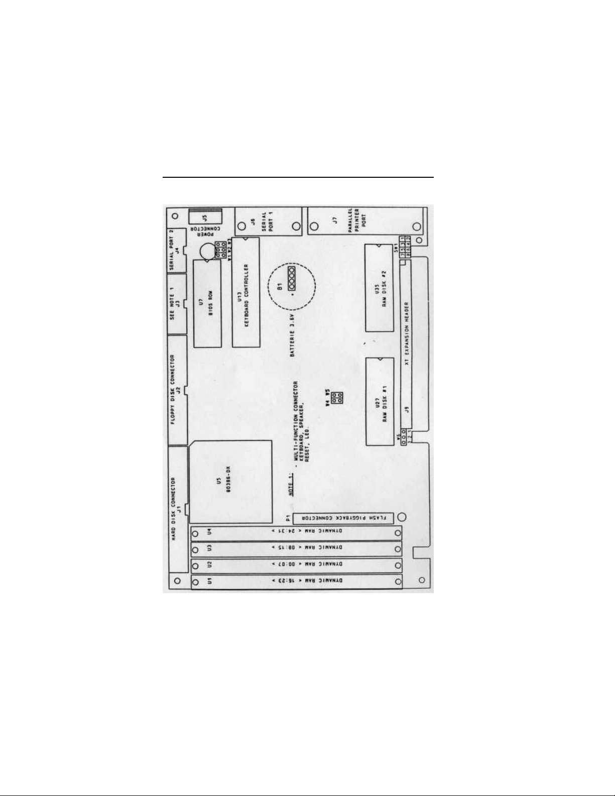
2-2 JUMPER LOCATIONS
MEMORY 11
Page 21
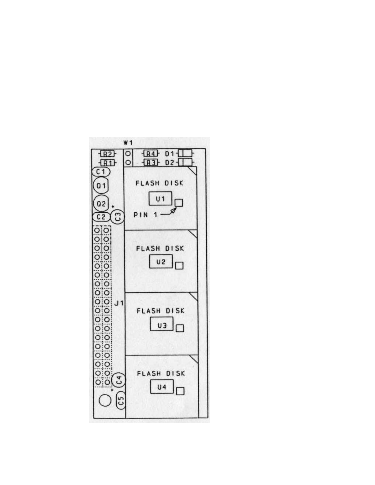
12 TEK-AT3 REFERENCE MANUAL
2-3 TEK753 FLASH EPROM BOARD
(Jumper Locations)
Page 22

MEMORY 13
MEMORY SECTION 3
3-1 MEMORY MAPPING
The TEK-AT3 supports 1, 4 or 16 Megabytes of
DRAM with parity check for system memory. You also
have room for up to 2M of solid state disks: U1-4 on
the TEK753 snap on daughterboard allow up to 1M of
Flash EPROM, and U27-U33 are reserved for up to 1M
of SRAM disk with battery backup protection.
3-2 SHADOW RAM
For efficient execution of BIOS, it is preferable to
execute BIOS code through RAM rather than through
the slower EPROMs. The TEK-AT3 provides the
shadow RAM feature which, if enabled, allows the
BIOS code to be executed from system RAM resident at
the same physical address as the BIOS EPROM.
F
3-3 EXPANDED MEMORY SYSTEM
The TEK-AT3 supports the LIM EMS 4.0 specification.
This specification allows the operating system and
software applications to access memory above the DOS
(1MB) limitation.
If Shadow RAM is enabled, the RAM
memory used for shadowing is no longer
available as user RAM.
Page 23

14 TEK-AT3 REFERENCE MANUAL
This is accomplished through the implementation of a
page mapping scheme that is managed by an EMS
driver. The TEK-AT3 also supports a combination of
expanded and extended memory.
3-4 CACHE MEMORY
Cache or cacheing is used to accelerate memory
accesses by providing a faster local storage memory.
This is accomplished by holding copies of data
frequently requested from main memory in much faster
SRAM. Which in turn enables the processor to run at
its full potential.
The TEK-AT3 comes with 16Kbytes of four-way high
performance Intel® 386 "Smart Cache". A four-way
cacheing scheme means more data paths are available
for frequently accessed code, thereby reducing the
average number of wait states seen by the CPU to
nearly 0.
Cacheing is a cost effective way of maximizing system
performance since it utilizes onboard memory for
operation. And because it is transparent to the user, you
don't have to spend time configuring your system for
optimum performance.
The TEK-AT3L uses Intel's Smart Cache 82395DX
and is located at socket U6.
Page 24

TEK-AT3 MEMORY MAPPING
EFFFFF
E80000
E7FFFF
E00000
DFFFFF
D80000
D7FFFF
D00000
CFFFFF
C80000
C7FFFF
C00000
200000 RESERVED
100000 1-2 Mbytes User RAM
0FFFFF
0F0000
0EFFFF
0EC000
0EBFFF
0C0000
0BFFFF
0A0000
09FFFF
000000
U4 Flash EPROMS
U3 Flash EPROMS
U43 Flash EPROMS
U42 Flash EPROMS
U38 RAM Backup
U29 RAM Backup
64K BIOS
BIOS Extension
112K User EPROM
128K Video RAM
640K User RAM
MEMORY 15
Page 25

16 TEK-AT3 REFERENCE MANUAL
Page 26

I/O MAP SECTION 4
The following table outlines the I/O ports used by the
TEK-AT3.
4-1 ONBOARD DECODED I/O MAP
Addresses Use
000-00F DMA controller 1
020-03F Interrupt controller 1
040-05F Timer
060-06F Keyboard(8742)
070-07F Real-time clock, NMI
mask
080-09F DMA page register
0A0-0BF Interrupt controller 2
0C0-0DF DMA controller 2
0F0-0FF Math coprocessor
1F0-1F7 HARD DISK
2x8-2xA EMS register,X=0 or 1
201 Watchdog timer, PDO,
User
278-27A LPT2
2F8-2FF COM2
378-37A LPT1
3F2-3F7 FLOPPY
3F8-3FF COM1
Page 27

18 TEK-AT3 REFERENCE MANUAL
Page 28

ONBOARD UTILITIES SECTION 5
5-1 DMA CONTROLLER (8237)
The TEK-AT3 supports seven direct memory access
(DMA) channels. Two DMA controllers, functionally
equivalent to the 8237, are used with four channels on
each chip. Channel 0 is reserved for the DRAM
refresh. Channel 4 is used to cascade channels 0
through 7 to the microprocessor.
5-2 INTERRUPT CONTROLLER (8259)
Two 8259 interrupt controllers handle the interrupts on
the TEK-AT3. Six interrupt lines are directly linked to
the keyboard controller timer, the real-time clock, both
serial ports and the parallel port.
5-2-1 INTERRUPT REGISTER ADDRESSES
Address Register
020 Operation control word 1
021 Operation control word 2/
control word 3
5-3 TIMER (8254)
The 8254 timer features three independent 16-bit
timer/counters. Channel 0 is tied to interrupt 0, channel
1 is used to generate a refresh, and channel 2 is used for
the speaker port.
Page 29

20 TEK-AT3 REFERENCE MANUAL
5-4 KEYBOARD
5-4-1 KEYBOARD CONTROLLER
The keyboard controller on the TEK-AT3 is a
single-chip microcomputer (Intel 8042) that is
programmed to support the keyboard serial interface.
The keyboard controller receives serial data from the
keyboard, checks data parity, translates scan codes, and
presents the data to the system as a byte of data in its
output buffer. The controller can interrupt the system
when data is placed in its output buffer, or wait for the
system to poll its status register to determine when data
is available.
Address Register
060 read Keyboard output buffer register
060 write Data write
064 write Command write
064 read Status register
KEYBOARD, SPEAKER, RESET, AND
KEYLOCK INTERFACE
Connector J3 on the TEK-AT3 provides all the
necessary signals for connecting all of the above
devices. The following diagram shows the signal
connections at J3:
PIN NUMBER PIN NUMBER
Page 30
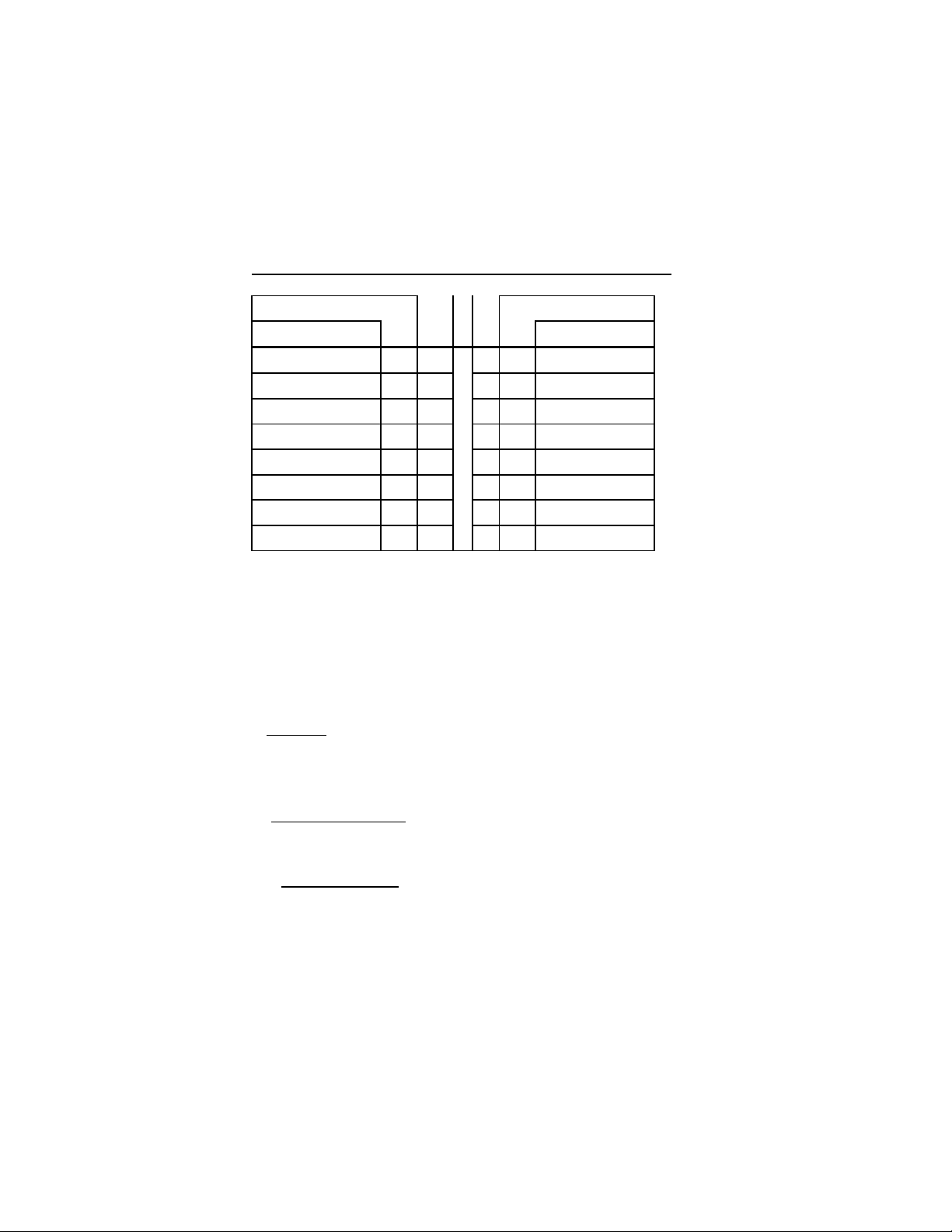
ONBOARD UTILITIES 21
SIGNAL FLOW SIGNAL FLOW
SIGNAL SIGNAL
KBDCLK 1 2 GND
KBDDATA 3 4 GND
VCC 5 6 VCC
SPKR 7 8 VCC
KBDINH 9 10 GND
AUTO* 11 12 GND
PBRES* 13 14 GND
ACT* 15 16 VCC
ACT*: Hard Disk LED
AUTO*: Refer to
Physical Devices Table
pg. 40
The following functions are available on the keyboard
header, J3:
i. Speaker: An 8ohm speaker can be directly connected
to J3-7 and J3-8. All necessary drivers are on the
TEK-AT3.
ii. Keyboard Disable: The keyboard can be disabled or
locked up by shorting J3-9 and J3-10.
iii. Hard Disk LED: The onboard IDE interface
activates an external LED. The LED must be connected
anode on J3-16 and cathode on J3-15. No external
current limiting resistor is required since one is already
present on the TEK-AT3.
Page 31

22 TEK-AT3 REFERENCE MANUAL
iv. Reset: The TEK-AT3 can be reset by shorting
J3-13 and J3-14.
v. Auto: This signal, J3-11, when shorted with J3-12,
puts the TEK-AT into Download Mode at boot up.
Auto has the same effect and is in parallel with SW1
7-8.
5-5 SUPERVISOR UTILITIES
5-5-1 WATCHDOG TIMER
The Watchdog Timer is extremely useful in embedded
systems where human supervision is not required.
Following a reset, the Watchdog is always disabled.
The Watchdog is enabled once you write "1" in bit "0"
at address 201 the first time. When it is enabled, the
microprocessor must refresh the Watchdog. This is
done by writing alternatively "0" and "1" to bit 1 at
address 201, once every 1.6 seconds to verify proper
software execution. If a hardware or software failure
occurs such that the Watchdog is not refreshed, a reset
pulse is generated by the Watchdog to restart the
processor.
F
The user program must provide the first
access to address 201, and must also include
the refresh routine.
Page 32

ONBOARD UTILITIES 23
5-5-1-1 WATCHDOG TIMER REGISTER
Address Register
201 bit 0 read/write Watchdog enable
201 bit 1 read/write Watchdog refresh
5-5-1-2 HARDWARE CONFIGURATION
Jumper W3 must be installed to permit activation of the
Watchdog. If jumper W3 is removed, the Watchdog is
disabled.
5-5-2 POWER FAILURE DETECTOR
The power failure detector, which generates a
non-maskable interrupt (NMI) when a failure occurs,
provides a 1.25V threshold for DC power fail warning,
low battery detection, or when monitoring a power
supply other than +5VDC. The Power Detection
Output (PDO) of the power failure detection circuit is
connected to IOCHECK (NMI). Jumper W2 allows the
user to disable this feature.
Power Monitoring
W2 Open* Power Monitor Disable
W2 Closed Power Monitor Enable
The detection circuit generates a non-maskable interrupt
when a power failure occurs. The status of the PDO is
available at address 201 bit D3.
Page 33

24 TEK-AT3 REFERENCE MANUAL
For example, if it reads 0, the circuit has detected a low
battery warning. Connector J5, pin 6, is used for the
power detection input. This input can only accept DC
voltage. The line is monitored via two external
resistors, R35 and R34=1K installed, which are
connected to the power failure input. The user should
install resistor R35 according to the monitoring level
desired.
EXAMPLE:
Assume the TEK-AT3 is powered by a 9V DC battery
and it is required that the battery be monitored for a low
battery warning at 7V DC. In this case, R35=4K7.
So, if the battery voltage goes below 7V, it will
generate a non-maskable interrupt and the status can be
read at address 201 bit D3. If bit D3 is 0, a low battery
is indicated.
Page 34

ONBOARD UTILITIES 25
Bear in mind that R35 and R34=1K installed should be
tailored to fit your specific application.
Please contact the factory for more details.
5-6 REAL-TIME CLOCK
The RTC is compatible with the popular MC146818. It
combines a complete time-of-day clock with a
one-hundred year calendar, an alarm, a programmable
periodic interrupt, and 114 bytes of low-power static
RAM. A battery backup facility is provided for the
RTC. The internal clock circuitry uses 14 bytes of this
RAM, and the rest is reserved for configuration
information.
Page 35

26 TEK-AT3 REFERENCE MANUAL
5-7 PARALLEL PORT (LPT1)
The parallel port is 100% PC/AT compatible. It
provides the necessary control signals for use as a
Centronics-compatible parallel interface. The
connection is done through a DB-25 connector, J7,
located at the edge of the board.
5-8 SERIAL COMMUNICATION PORTS
The TEK-AT3 features two UARTs which are
functionally equivalent to the NS16450. They are both
configured as DTE. The COM1 (J6) port is buffered
directly on the board for RS232 operation. The COM2
(J4) port is buffered for RS232 or for RS485. If you
require RS485 on COM2, you must specify it as
OPT-300 when placing your order.
Page 36
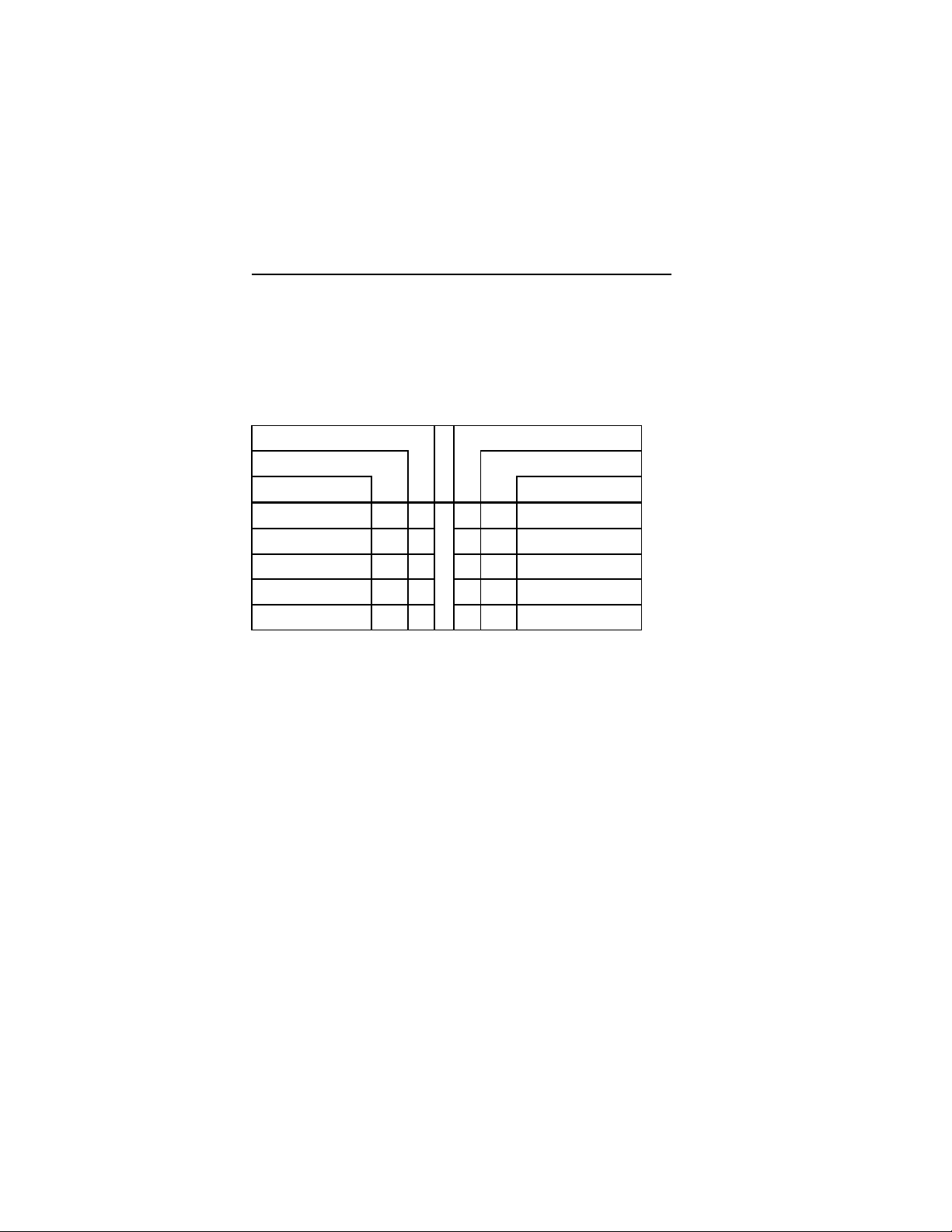
ONBOARD UTILITIES 27
5-8-1 COM1 (J6) HARDWARE
CONFIGURATION
The COM1 port is configured as RS232, and is 100%
compatible with the IBM-AT serial port.
J6 (COM1)
PIN NUMBER PIN NUMBER
SIGNAL FLOW SIGNAL FLOW
SIGNAL SIGNAL
DCD IN 1 6 IN DSR
RX IN 2 7 OUT RTS
TX OUT 3 8 IN CTS
DTR OUT 4 9 IN RI
GND OUT 5
Page 37
28 TEK-AT3 REFERENCE MANUAL
5-8-2 COM2 (J4) HARDWARE
CONFIGURATION
5-8-2-1 COM2 (J4) as RS232
The COM2 port is configured as RS232, and is 100%
compatible with the IBM-AT serial port.
J4 (COM2) RS232
PIN NUMBER PIN NUMBER
SIGNAL FLOW SIGNAL FLOW
SIGNAL SIGNAL
DCD IN 1 2 IN DSR
RX IN 3 4 OUT RTS
TX OUT 5 6 IN CTS
DTR OUT 7 8 IN RI
GND 9
F
The pinout for J6 and J4, shown on the
previous page, may seem different. However,
since J4 (COM2) is a 10 pin flat ribbon
connector, the flat ribbon cable will produce
an identical pinout as J6 (COM1) when
crimped to a DB9 connector as long as pin 1
is kept aligned.
Page 38

ONBOARD UTILITIES 29
5-8-2-2 COM2 (J4) as RS485
If the TEK-AT3 is configured for RS485 operation. It
can support either full-duplex or party line
communication.
5-8-2-2-1 FULL DUPLEX OPERATION
Upon power-up or reset, the RS485 interface circuits
are automatically configured for full duplex operation.
J4(3,4) act as the receiver lines and J4(5,6) as the
transmitter lines.
5-8-2-2-2 PARTY LINE OPERATION
In order to enable party line operation, the user must
first write "1" to bit 3 at I/O address 201. This allows
the transceiver J4(3,4) to be controlled by the RTS
signal. Upon power-up or reset, the transceiver is by
default in "receiver mode" in order to prevent unwanted
perturbation on the line.
Page 39
30 TEK-AT3 REFERENCE MANUAL
In party line operation, termination resistors R5 and R6
must be installed only on the boards at both ends of the
network.
J4 (COM2) RS485
PIN NUMBER PIN NUMBER
SIGNAL FLOW SIGNAL FLOW
SIGNAL SIGNAL
RESERVED IN 1 2 IN NC
RXD(-) I/O 3 4 OUT RXD(+)
TXD(-) OUT 5 6 IN TXD(+)
NC OUT 7 8 IN NC
GND IN 9
5-9 FLOPPY DISK CONTROLLER
The floppy disk controller on the TEK-AT3 is IBM PC
and AT compatible (single and double density). It
handles 3.5 and 5.25 inch low and high density drives.
Up to two drives in any combination can be supported.
Page 40

ONBOARD UTILITIES 31
5-9-1 3.5" AND 5.25" FLOPPY DISK
INSTALLATION
The installation of floppy drives on the TEK-AT3 is
done via a standard IBM 34-pin flat ribbon cable that
connects to J2. The pin-out is described below:
Pin number Signal Flow Signal
2 OUT RPM/LC
4 - N.C.
6 - N.C.
8 IN INDEX*
10 OUT MOTRENA*
12 OUT DRIVESB*
14 OUT DRIVESA*
16 OUT MOTRENB*
18 OUT DIRC*
20 OUT STEP*
22 OUT WRIT DATA*
24 OUT WRIT ENABLE*
26 IN TRACK0*
28 IN WRIT
PROTECT*
30 IN READ DATA*
32 OUT HEAD SELECT*
34 IN DCHG
1-33 ODD GND
Page 41

32 TEK-AT3 REFERENCE MANUAL
5-10 HARD DISK CONTROLLER
The TEK-AT3 supports AT Integrated Disk Drives.
The AT embedded drive architecture incorporates drive
electronics and controller circuitry on a single printed
circuit board which is mounted directly to the disk drive
chassis. The integration of drive and controller
functions increases reliability and performance by
eliminating redundant circuitry. Thus, providing
increased performance at reduced cost.
5-10-1 HARD DISK INSTALLATION
To connect an IDE hard disk to the TEK-AT3, a 40-pin
dual row header signal connector is required. This
connector handles all command, data, and status I/O
lines. The 40-pin male header connector located at J1
on the TEK-AT3 connects directly with the cable.
1. Signal connector - 2 X 20-pin right vertical .1 inch
Berg Stick REF: P/N AMP 2-102444-0
Maximum Cable length - 18 inches
Page 42

ONBOARD UTILITIES 33
The drive itself can be mounted in any horizontal or
vertical plane.
F
5-10-2 PIN OUT OF HARD DISK INTERFACE
CONNECTOR
Pin number Signal Flow Signal
3 I/O SD7
4 I/O SD8
5 I/O SD6
6 I/O SD9
7 I/O SD5
8 I/O SD10
9 I/O SD4
10 I/O SD11
11 I/O SD3
12 I/O SD12
13 I/O SD2
14 I/O SD13
15 I/O SD1
16 I/O SD14
17 I/O SD0
18 I/O SD15
The hard disk interface can be disabled on
the TEK-AT3 by installing jumper W4. This
allows you to install other types of hard disk
interfaces.
Page 43

34 TEK-AT3 REFERENCE MANUAL
1 I RST23 I IOW25 I IOR33 I SA1
35 I SA0
36 I SA2
37 I CS038 I CS1
31 O IRQ14
32 O I/OCS1639 O ACTIVE
8 RESERVED(NOT CONNECTED)
20 KEY(NOT CONNECTED)
21 RESERVED(NOT CONNECTED)
34 - PDIAG
2,19,22,24 - GND
26,30,40
5-11 SOLID STATE DISKS
The TEK-AT3 comes standard with a snap-on
daughterboard specially designed to carry from 128K to
1M of Flash EPROM solid state (semiconductor) disks.
Solid state disks have no moving parts and are far less
susceptible to dirt, moisture, vibration and temperature
variations than mechanical Winchester and floppy
disks.
Two sockets on the TEK-AT3 itself are reserved for the
battery-backed SRAM disk. Up to 1Mbyte is available
by using 512Kx8 devices. Files transferred to
Page 44

ONBOARD UTILITIES 35
battery-backed RAM disks stay resident for a minimum
of one year; 5 years typically.
Flash memories enable code version updates to be
downloaded. A central host computer can download
program codes to many remote systems. Flash memory
is a solid-state, nonvolatile disk. Thus eliminating the
risk of losing updates (a concern with battery backed
RAM). These aspects of Flash memory offer major
advantages in automated factories, remote systems,
portable equipment and other applications. Finally,
Flash memory provides this capability at a much lower
cost than EEPROM or battery-backed SRAM.
5-11-1 INSTALLATION
5-11-1-1 USER CONFIGURATION
The TEK-AT3 semiconductor disk section does not
require any jumper configuration except for the battery
back-up, the write protect option, and the SRAM
memory type.
User EPROM/Flash EPROM Disk
The TEK-AT3 supports four 32-pin Lead PLCC's for
user EPROM and/or Intel Flash EPROMS, model
28F010, 128Kx8 or model 28F020,
256Kx8 via the TEK753 snap-on daughterboard (refer
to the TEK753 assembly layout in the Specifications
section). Sockets U1-4 accept the devices. The virtual
disk utility automatically detects what type of device is
Page 45

36 TEK-AT3 REFERENCE MANUAL
installed and how much memory is present.
Flash Installed
Jumper W1 on the TEK753 must be installed when
Flash EPROM devices are present. If EPROM devices
are installed, remove jumper W1.
User RAM Disk
U23 and U33 on the TEK-AT3 support 32Kx8,
128Kx8, 256Kx8 or 512Kx8 SRAM devices. The
virtual disk utility automatically detects what type of
device is installed and how much memory is present.
RAM Disk Memory Type
W6(A-B) 32Kx8 or 128Kx8 SRAM devices
W6(B-C) 256Kx8 or 512Kx8 SRAM devices
5-11-2 BATTERY BACK-UP
A 350maH lithium battery is installed on the TEK-AT3.
If the TEK-AT3 is strapped to be powered by the
battery backup, the RAMs will retain their information
after a power down.
W1 Open NC
W1 Closed Vbatt
F
Removing jumper W1 will cause the set-up
and real-time clock information to be lost.
Page 46

ONBOARD UTILITIES 37
The TEK-AT3 comes with a 350 maH TL5186
TADIRAN battery with a shelf life of approximately 10
years (under "no load" conditions).
TEK-AT3 draws approximately 10µA typical. This
means the battery will last 4 years if no power is applied
to the board. Remember, when the 5V is supplied, the
battery is electronically disconnected - virtually as if it
were on the shelf.
The actual life of the battery depends on the amount of
time DC power is not applied and on environmental
(temperature) conditions. The TADIRAN TL5186 has
an operating range of -550 to 750C and discharge
characteristics vary with temperature.
Page 47

38 TEK-AT3 REFERENCE MANUAL
Page 48

OPERATION SECTION 6
6-1 CONFIGURATION JUMPERS(SW1)
The TEK-AT3 has an onboard BIOS extension which
controls certain functions of the BIOS related to
industrial applications. The extended BIOS reads the
status of the jumpers (SW1) and acts accordingly.
Upon system start-up, the BIOS automatically
determines how much ROM/RAM disk memory is
available to the system, and what equipment is
connected to the system. Jumpers SW1 will be set by
the user as needed. The following lists the available
modes:
SW1
(1-2) Boot From Flash Devices
(3-4) Mono/color
(5-6) Boot From VT100 Terminal
(7-8) Activate Serial Download Mode
6-2 LOGICAL DISK CONFIGURATION
The TEK-AT3 can detect two semiconductor drives - A
Flash EPROM disk drive and a battery-backed SRAM
disk drive.
Page 49

40 TEK-AT3 REFERENCE MANUAL
These drives are installed as follows:
If SW1(1-2) is installed (i.e. booting operating system
from Flash EPROMs), then Drive A: is the Flash Disk
(assuming a valid Flash Disk is placed in sockets U1-4
on TEK753 daughterboard). Drive B: is Floppy 1 (if
installed) or the next available drive according to the
following list of priorities:
1- Floppy 1
2- Flash Disk if not already installed as A:
3- RAM Disk (if installed)
4- Hard Disk (if installed)
Subsequent logical drives are installed following the
above priority list.
If SW1(1-2) is not installed (i.e. booting operating
system from F/H drives), then Drive A: is Floppy 0.
Drive B:, and subsequent drives, follow the priority list
above.
Please refer to the Physical Devices Table for complete
information.
F
The RAM disk is automatically detected and
installed upon booting. The beginning of the
disk is checked and reformatted if it is found to
be corrupt or if data is unrecognizable.
Page 50
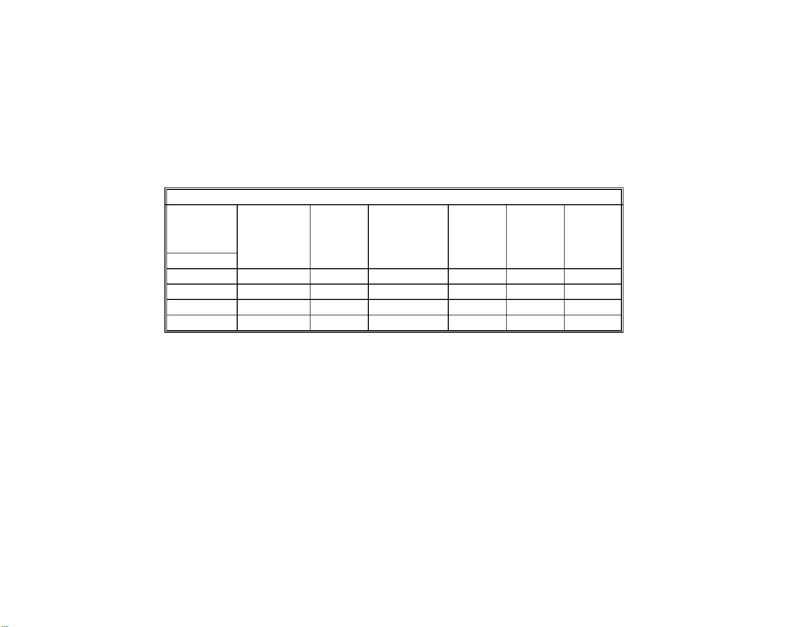
PHYSICAL DEVICES TABLE
PHYSICAL DEVICES INSTALLED & DRIVE ASSIGNMENTS
CONFIGURATION
AND PHYSICAL
DEVICES
INSTALLED
DRIVE NAME:
A: FLOPPY 0 FLOPPY 0 FLASH FLOPPY 0 FLASH FLASH
B: FLOPPY 1 FLOPPY 1 FLOPPY 1 FLASH FLOPPY 1 AVAILABLE
C: AVAILABLE FLASH AVAILABLE AVAILABLE AVAILABLE AVAILABLE
D: AVAILABLE AVAILABLE AVAILABLE AVAILABLE AVAILABLE AVAILABLE
JUMPER OR
NO JUMPER
FLOPPY 0
FLOPPY 1
NO FLASH DISK
NO JUMPER
FLOPPY 0
FLOPPY 1
FLASH DISK
JUMPER
FLOPPY 0 OR
NO FLOPPY 0
FLOPPY 1
FLASH DISK
NO JUMPER
FLOPPY 0
FLASH DISK
JUMPER
FLOPPY 1
FLASH DISK
JUMPER
FLASH DISK
NOTES: The indication "FLASH DISK" assumes at least one Flash device is installed at U26 with a valid
DOS content. "Floppy 0" specifies the physical drive connected to the twisted end of the flat
cable. "Floppy 1" specifies the physical drive connected to the untwisted end of the flat cable.
"Jumper" specifies configuration Jumper SW1(1-2). All other drives are installed following the
above assignments in this manner: RAM Disk, and then Hard Disk. Therefore, with a full
configuration, RAM Disk is "D" and the Hard Disk is "E".
Page 51

42 TEK-AT3 REFERENCE MANUAL
6-3 VT100 OPERATION (SW1(5-6))
The TEK-AT3 utilizes a feature known as VT1OO
MODE. This mode enables your single board computer
to run without a local keyboard or screen. That is,
operation can be controlled via a remote terminal or a
computer with a terminal emulation program.
6-3-1 REQUIREMENTS
To use VT100 Mode, the TEK-AT board must be
supplied with +/-12 volts. This is the voltage required
by the RS232 drivers.
The terminal you are using should emulate a VT1OO or
ANSI terminal. Although this is not an absolute
requirement, strange characters may appear on screen if
it does not. This occurs because the VT1OO recognizes
these control characters, and causes them to perform a
specific function. For example, screen erase, cursor
position,etc..
6-3-2 HARDWARE SETUP AND
CONFIGURATION
Follow these steps to setup for VT1OO Mode:
• Install jumper SW1(5-6) to enable VT1OO
Mode
{note: VT1OO Mode runs on COM1 (3F8H)}
.
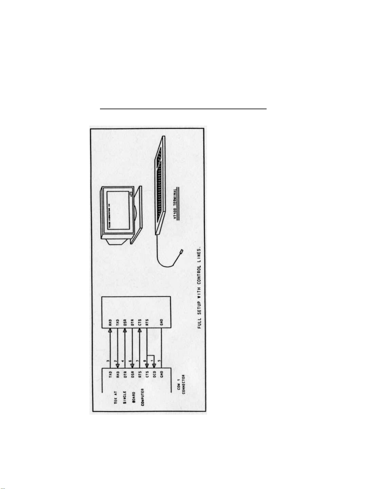
• Setup the communications cable as shown in
Diagram 6.3A
{Note: If you do not require a full cable
Page 52

OPERATION 43
for your terminal, you can setup a partial cable using only the
TXD and RXD lines. The control lines can be ignored by
looping them back as shown in Diagram 6.3B
}.
• Boot up your terminal and set it up with the
following parameters:
19200 Baud
8 Bits
No Parity
Echo off (or full duplex)
F
Use CTRL-R to configure your system in
VT100 Mode.
6-3-3 RUNNING WITHOUT A TERMINAL
If you wish to disconnect the VT1OO terminal or if you
decide to run without a terminal, you must ensure the
control lines are in an active state. Failing this, the
system may "hang" while waiting for the control lines
to become active. Wiring the system according to
Diagram 6.3B allows the lines to remain active.
Furthermore, you can run without any console at all
simply by not enabling VT1OO mode and by not
installing a video card.
Page 53
44 TEK-AT3 REFERENCE MANUAL
DIAGRAM 6A
Page 54
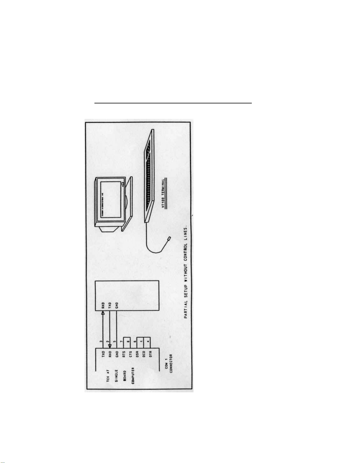
DIAGRAM 6B
OPERATION 45
Page 55

46 TEK-AT3 REFERENCE MANUAL
6-3-4 DISK DRIVES AND SEMI CONDUCTOR
DISKS
All disk drives and semi conductor disks operate
identically in both regular and VT1OO mode, and all
drive assignments remain the same.
Downloading software to Flash devices is done through
XFLASH, Teknor's transfer utility software. Please
refer to the XFLASH user's manual for details.
6-3-5 BAUD RATE RESTRICTIONS
The baud rate is re-initialized each time a call to INT
1OH (display to console) is made. This is due to some
software programs, such as MS-DOS, changing the
baud rate when loading.
6-4 GRAPHICS/STAND-ALONE (SW1(5-6))
The TEK-AT3 can operate without any video
controller, keyboard or mechanical drives. The
TEK-AT3 will automatically detect the presence of
video, keyboard and mechanical drive devices and act
accordingly. The TEK-AT3 can be used with the
TEK-PG VGA card or any IBM compatible graphics
controller card. Before starting the system, the user
should also verify that the color monitor attached to the
system can support the desired graphics mode.
Page 56

TEK-AT3 BIOS 47
TEK-AT3 BIOS SECTION 7
7-1 OVERVIEW AND FEATURES
The TEK-AT3 uses the Quadtel BIOS. This BIOS
provides a software interface between the operating
system and the hardware of the TEK-AT3 single board
computer. The interface provided by the BIOS is 100%
IBM AT compatible. That is, all functions accept the
same inputs and provide the same results, although the
program code itself is different.
7-2 ERROR HANDLING
TEKNOR BIOS can be configured to handle errors
differently. Two possibilities exist:
Stop: The BIOS will stop the booting process
if an error is detected and request the
user to press F1.
Warning: The BIOS will display an error message
but will continue the booting procedure.
Page 57

48 TEK-AT3 REFERENCE MANUAL
The following lists the error sources and their default
values.
[Warning] Diskette
[Warning] Fixed Disk
[Warning] Keyboard
[Warning] Video
[Warning] Memory size
[Warning] CMOS checksum
[Warning] Real-Time Clock
[Warning] POST configuration
[Warning] Coprocessor
[Warning] Other
Page 58

SPECIFICATIONS 49
SPECIFICATIONS SECTION 8
8-1 DC CHARACTERISTICS
Supply Voltage Vcc min.: 4.75V
Vcc max.: 5.25V
+12V
-12V
Supply Current Icc typ.: 1.5A
1
Ipp +12V 10ma
Ipp -12V 5ma
8-2 ENVIRONMENTAL SPECIFICATIONS
Operating Temperature:
00C to 700C
-400C to +850C Available
Non-Condensing relative humidity:
5% to 95%
1. This current was measured with 4Mbytes of RAM.
Page 59
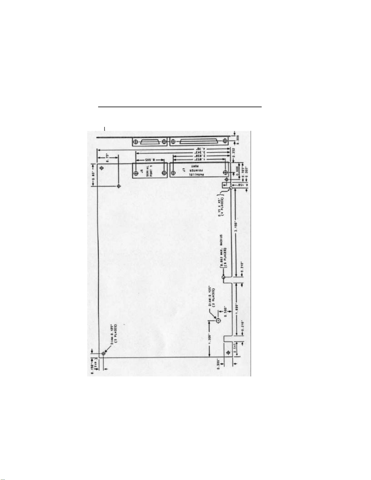
50 TEK-AT3 REFERENCE MANUAL
8-3 MECHANICAL SPECIFICATIONS
Page 60
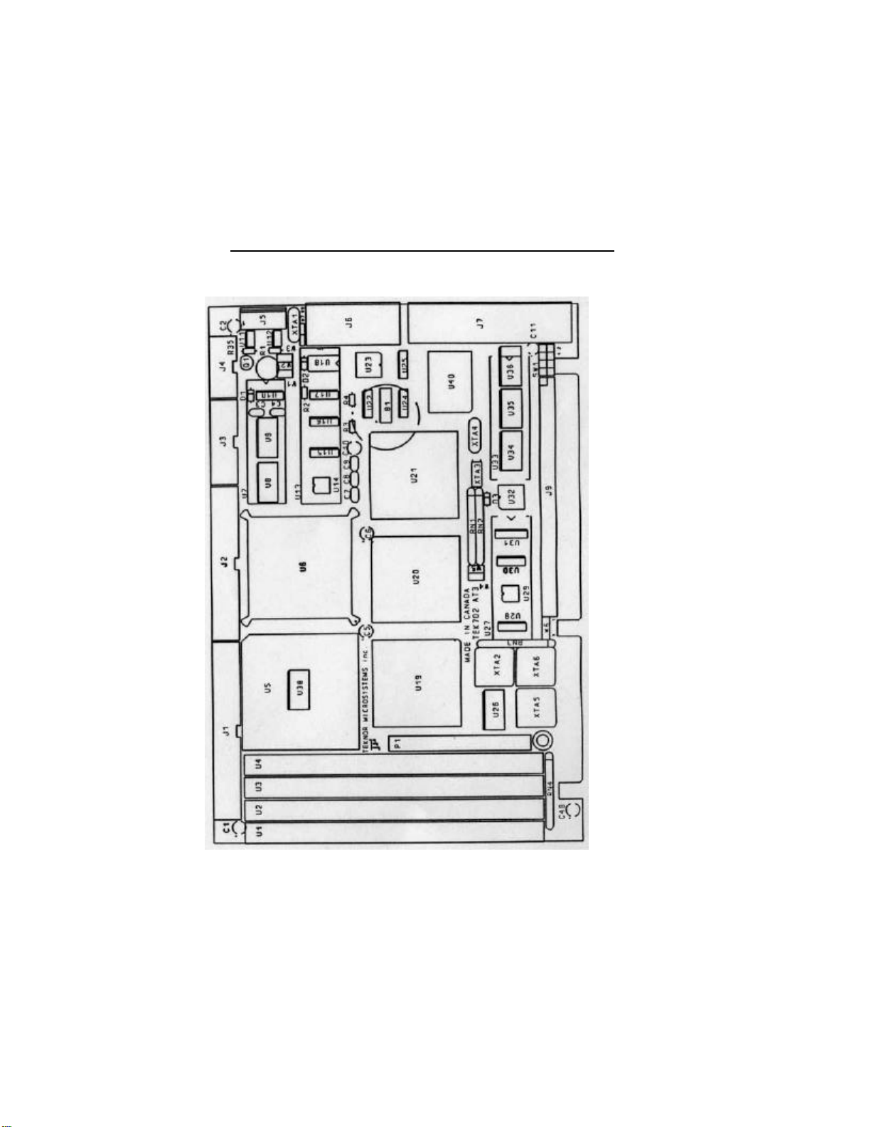
8-4 ASSEMBLY
SPECIFICATIONS 51
Page 61
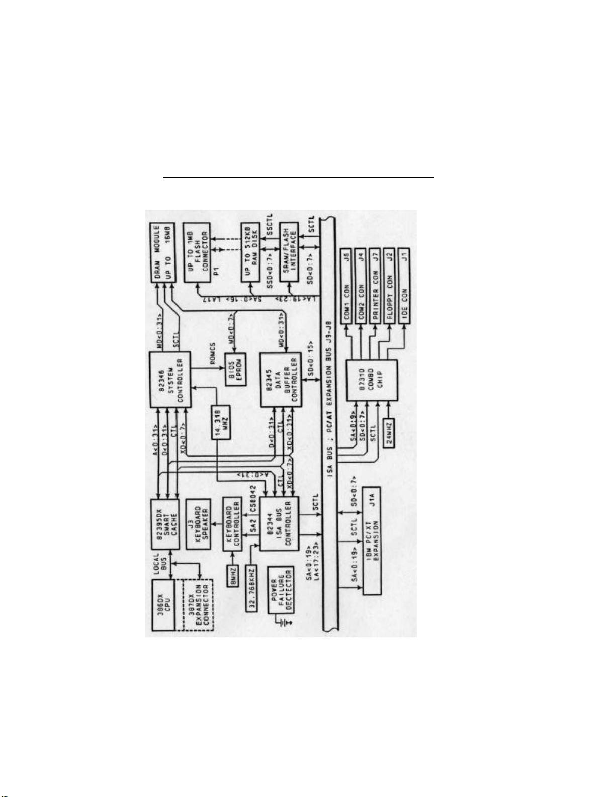
52 TEK-AT3 REFERENCE MANUAL
8-5 BLOCK DIAGRAM
Page 62
SPECIFICATIONS 53
8-6 CONNECTOR OVERVIEW
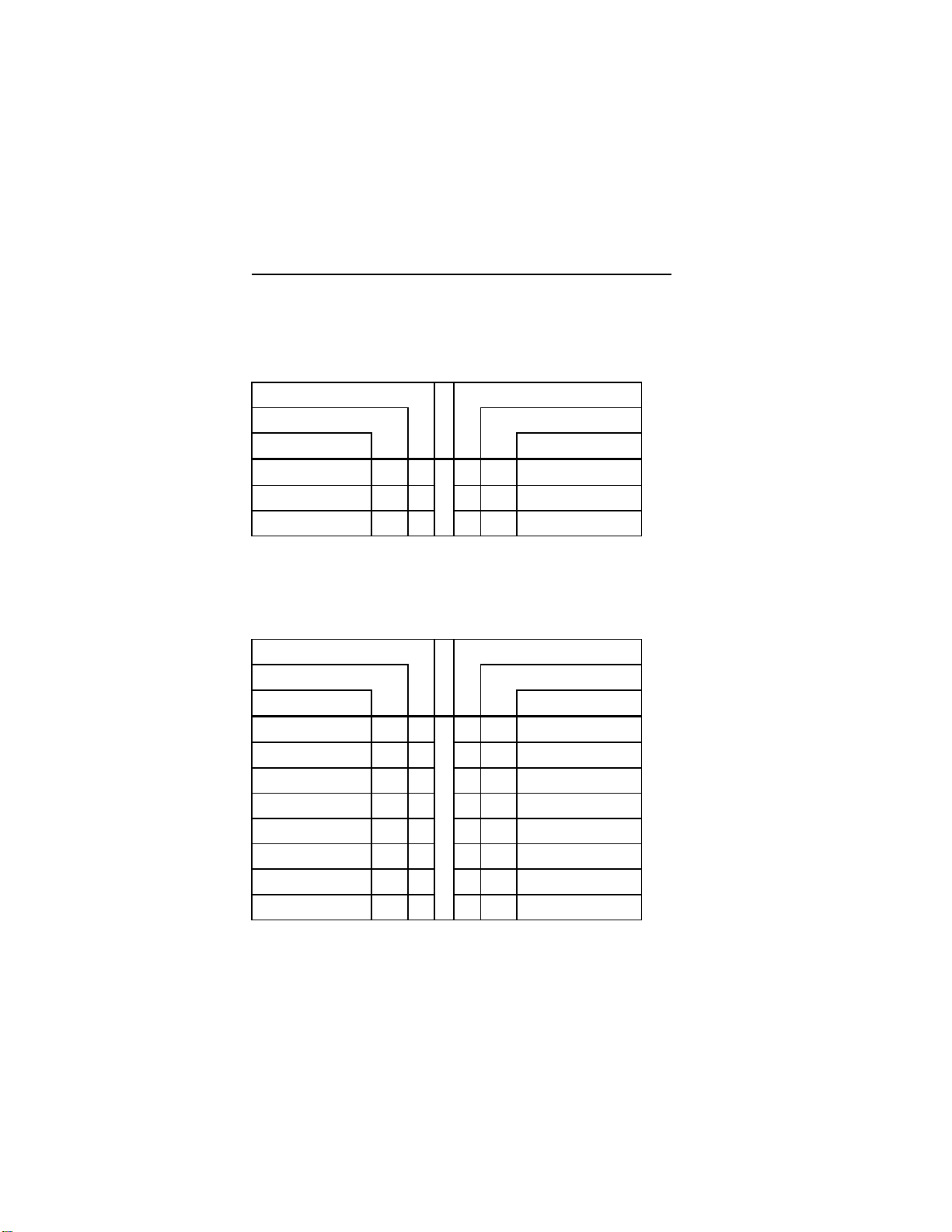
8-6-1 J5 POWER CONNECTOR
PIN NUMBER PIN NUMBER
SIGNAL FLOW SIGNAL FLOW
SIGNAL SIGNAL
VCC 1 2 GND
GND 3 4 +12V
-12V 5 6 PD
8-6-2 J3 KEYBOARD CONNECTOR
PIN NUMBER PIN NUMBER
SIGNAL FLOW SIGNAL FLOW
SIGNAL SIGNAL
KBDCLK 1 2 GND
KBDDATA 3 4 GND
VCC 5 6 VCC
SPKR 7 8 VCC
KBDINH 9 10 GND
AUTO* 11 12 GND
PBRES* 13 14 GND
ACT* 15 16 VCC
Page 63
54 TEK-AT3 REFERENCE MANUAL
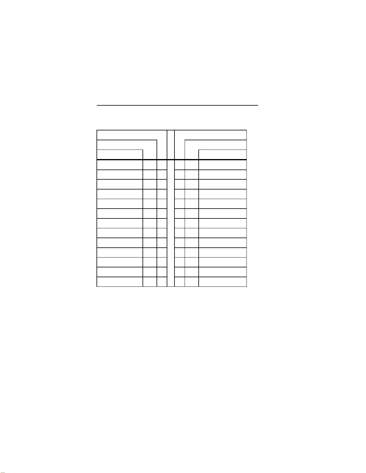
8-6-3 J7 PRINTER CONNECTOR
PIN NUMBER PIN NUMBER
SIGNAL FLOW SIGNAL FLOW
SIGNAL SIGNAL
STB* 1 14 AFD*
P0 2 15 ERR*
P1 3 16 INIT*
P2 4 17 SLIN*
P3 5 18 GND
P4 6 19 GND
P5 7 20 GND
P6 8 21 GND
P7 9 22 GND
ACK* 10 23 GND
BUSY 11 24 GND
PE 12 25 GND
SLCT 13
Page 64
SPECIFICATIONS 55
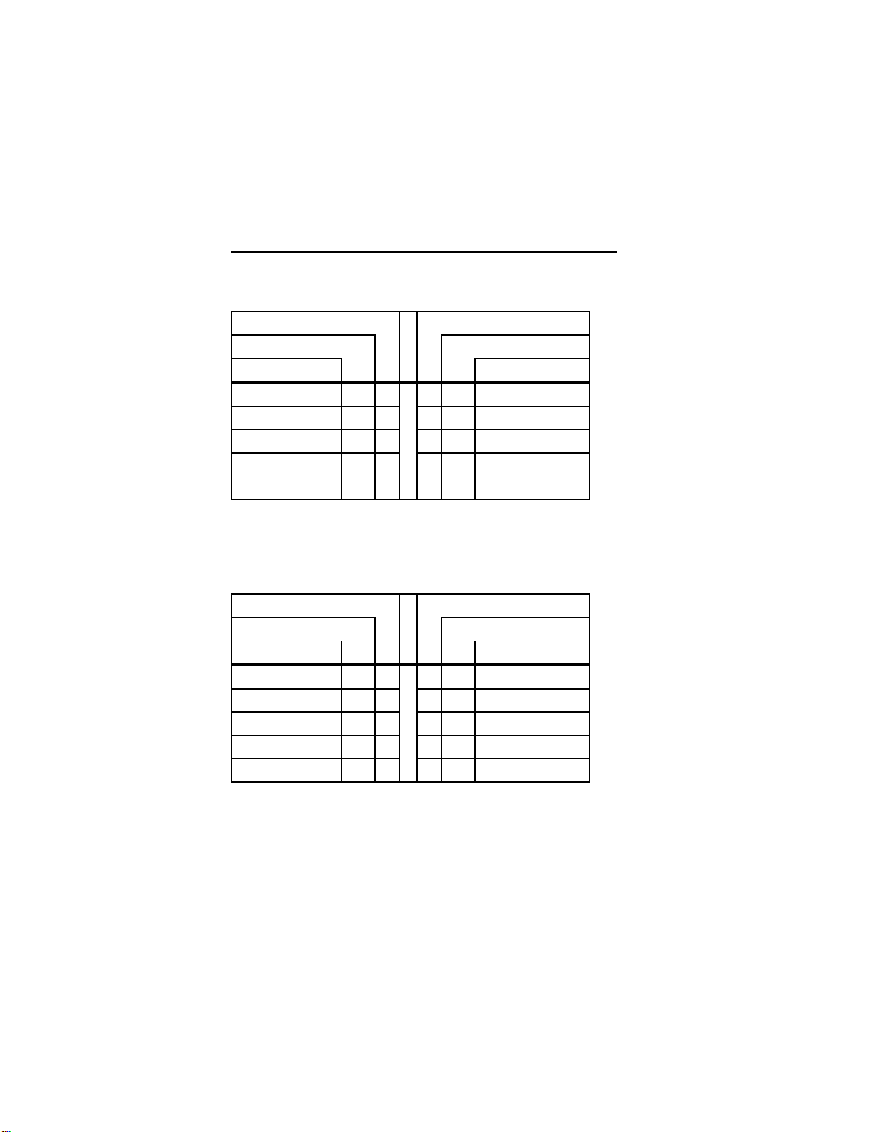
8-6-4 J6 COM1 CONNECTOR
J6 (COM1)
PIN NUMBER PIN NUMBER
SIGNAL FLOW SIGNAL FLOW
SIGNAL SIGNAL
DCD IN 1 6 IN DSR
RX IN 2 7 OUT RTS
TX OUT 3 8 IN CTS
DTR OUT 4 9 IN RI
GND OUT 5
8-6-5 J4 COM2 CONNECTOR RS232
J4 (COM2) RS232
PIN NUMBER PIN NUMBER
SIGNAL FLOW SIGNAL FLOW
SIGNAL SIGNAL
DCD IN 1 2 IN DSR
RX IN 3 4 OUT RTS
TX OUT 5 6 IN CTS
DTR OUT 7 8 IN RI
GND 9
Page 65
56 TEK-AT3 REFERENCE MANUAL
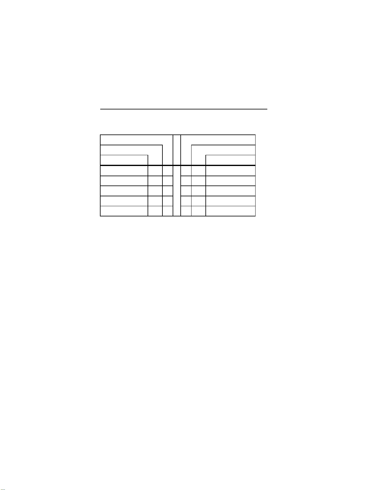
8-6-6 J4 COM2 CONNECTOR RS485
J4 (COM2) RS485
PIN NUMBER PIN NUMBER
SIGNAL FLOW SIGNAL FLOW
SIGNAL SIGNAL
RESERVED IN 1 2 IN NC
RXD(-) I/O 3 4 OUT RXD(+)
TXD(-) OUT 5 6 IN TXD(+)
NC OUT 7 8 IN NC
GND IN 9
Page 66

LIMITED WARRANTY SECTION 9
TEKNOR MICROSYSTEMS INC. ("the seller")
warrants its products to be free from defects in material
and workmanship for a period of two (2) years
commencing on the date of shipment. The liability of
the seller shall be limited to replacing or repairing, at
the seller's option, any defective units. Equipment or
parts which have been subject to abuse, misuse,
accident, alteration, neglect, or unauthorized repair are
not covered by this warranty. This warranty is in lieu of
all other warranties expressed or implied.
Returning Defective Merchandise
If your TEKNOR product malfunctions, please do the
following before returning any merchandise:
1) Call our Technical Support Department at (514)
437-5682. Make certain you have the
following at hand: the Teknor Invoice #, your
Purchase Order #, and the Serial Number of the
defective unit.
2) Give the serial number found on the back of the
card and explain the nature of your problem to a
service technician.
3) If the problem cannot be solved over the
telephone the technician will further instruct you
on the return procedure.
4) When returning goods, please include the name
Page 67

58 TEK-AT3 REFERENCE MANUAL
and telephone number of a person whom we can
contact for further explanations if necessary.
Where applicable, always include all duty
papers and invoice(s) associated with the
item(s) in question.
5) Prior to returning any merchandise, make certain
you receive an RMA # and clearly mark this
number on the outside of the package you are
returning.
6) When returning a TEKNOR card:
i) Make certain that the card is packed
in conductive foam pads or conductive
plastic bags.
ii) Place it in a rigid cardboard box.
iii) Ship prepaid and insured to:
TEKNOR MICROSYSTEMS INC.
Service Department
31 de la Seigneurie E.
Suite 107
Blainville, Quebec
J7C 4G6 CANADA
GETTING HELP SECTION 10
Need More Help?
At Teknor, we take great pride in our customer's
successes. We strongly believe in providing full
Page 68

GETTING HELP 59
support at all stages of your product development.
If at any time you encounter difficulties with your
application or with any of our products, or if you simply
need guidance on system setups and capabilities, you
may contact our Technical Services/Support
Department at
Tel: (514) 437-5682
Fax: (514) 437-8053
If you have any questions about Teknor, our products
and/or services, you may reach us at the above numbers
or by writing to:
TEKNOR MICROSYSTEMS INC.
31 de la Seigneurie E.
Suite 107
Blainville, Quebec
J7C 4G6 CANADA
Page 69

60 TEK-AT3 REFERENCE MANUAL
Page 70

RECOMMENDED DEVICES
The following is a list of recommended devices for use
on the TEK-AT3. Many other devices are also
available and function equally well. Users are
encouraged to check with their local memory
distributors for comparable substitutes.
DRAM (U1-U4)
DRAM devices with page mode at 80ns maximum
access time, or better, should be used. E.g.:
SIEMENS HYM910005 (1M x 9)<T>
TOSHIBA THM91000A5-80 (1M X 9)
HITACHI HB56A19B-8 (1M x 9)
OKI MSC2312A159-8A/80 (1M x 9)
SRAM (U27-U33)
Static RAM CMOS memory with low power
consumption for battery backup (no Pseudo-Static) with
access time of 200ns, or better. Must be in DIP
package. E.g.:
SONY 58256P (32K x 8)
MITSUBISHI MH12808TNA-15 (128K x 8)
MITSUBISHI MH51208TNA-15 (512K x 8)
Page 71

ii TEK-AT3 REFERENCE MANUAL
EDI 8M8 128/LP (128K x 8)
EDI 8F8257/LP (256k x8)
EDI 8F8512/LP (512K x 8)
or equivalents.
FLASH EPROM (U1-4)
Use Flash EPROM's with 200ns access time, or better.
Must be in PLCC package. Use only:
INTEL or AMD 28F010 (128K x 8) FLASH EPROM
INTEL or AMD 28F020 (256K x 8) FLASH EPROM
INTERFACE CONNECTORS
The following connectors are recommended for
interfacing with the TEK-AT4 I/O devices. The parts
shown here do not have a strain relief but one may be
added.
Connector Recommended Mating Part
Hard Disk (J1) Robinson Nugent IDS-C40PK-TG
Amp 746286-9 (499252-1*)
Thomas & Betts 609-1041
(40-pin flat cable connector)
Page 72

APPENDIX A iii
Floppy Disk (J2) Robinson Nugent IDS-C34PK-TG
Amp 746286-8 (499252-6*)
Thomas & Betts 609-3441
(34-pin flat cable connector)
Keyboard (J3) Robinson Nugent IDS-C16PK-TG
Amp 746286-3 (499252-8*)
Thomas & Betts 609-1641
(16-pin flat cable connector)
COM2 (J4) Robinson Nugent IDS-C10PK-TG
Amp 746286-1 (499252-5*)
Thomas & Betts 609-1041
(10-pin flat cable connector)
Power Connector (J5) Leoco 2530 S060013 (housing)
Leoco 2533 TCB00A0 (pins)
Molex 22-01-2065 (housing)
Molex 08-50-114 (pins)
COM1 (J6) Robinson Nugent
IDD-C9SM-440-TG30
Amp 747318-4 (747275-4*)
Thomas & Betts 609-09S
Amphenol 841-17-DBFR-B9S
(9-pin flat cable connector)
LPT1 (J7) Robinson Nugent
IDD-C25PM-440-TG30
Page 73

iv TEK-AT3 REFERENCE MANUAL
Amp 747321-2 (747275-2*)
Thomas & Betts 609-25P
Amphenol 841-17-DBFR-B25P
(25-pin flat cable connector)
XT Header (J9) Samtec ESQ131-12-G-D
PCB-mount female connector
* optional Amp strain relief part number shown in bracket
 Loading...