

Page 1

Climatizzatore Multisplit
Multisplit air conditioner
Manuale installatore
Installation manual
Page 2
I prodotti elettrici ed elettronici di eventuale scarto dovranno essere disposti con i normali rifiuti domestici, ma
smaltiti a norma di legge RAEE in base alle direttive Europee 2002/96/CE e successive modifiche 2003/108/CE,
informandosi presso il Comune di residenza o presso il rivenditore nel caso in cui il prodotto venga sostituito
con uno analogo.
Possible wasted electrical or electronic devices/products should not be located together with normal
domestic waste, but disposed according to the current WEEE law in compliance with the European
Directive 2002/96/EC and following modifications 2003/108/EC. Please inform yourself at your local
Page 3

2
ITALIANO
INDICE
1. INFORMAZIONI IMPORTANTI ............................................................................................................................. 3
2. COMPONENTI....................................................................................................................................................... 4
3. DISPLAY ................................................................................................................................................................ 4
4. DESCRIZIONE TELECOMANDO ......................................................................................................................... 5
4.1. Descrizione funzioni tasti del telecomando ........................................................................................................ 5
4.2. Descrizione indicatori del display ....................................................................................................................... 5
4.3. Come inserire/sostituire le batterie..................................................................................................................... 6
4.4. Come utilizzare il telecomando per far funzionare l’unità .................................................................................. 6
5. MANUTENZIONE .................................................................................................................................................. 9
6. OPERAZIONI E PRESTAZIONI.......................................................................................................................... 10
7. MALFUNZIONAMENTI........................................................................................................................................ 12
8. INSTALLAZIONE................................................................................................................................................. 13
9. PROVA DI FUNZIONAMENTO........................................................................................................................... 18
Page 4
3
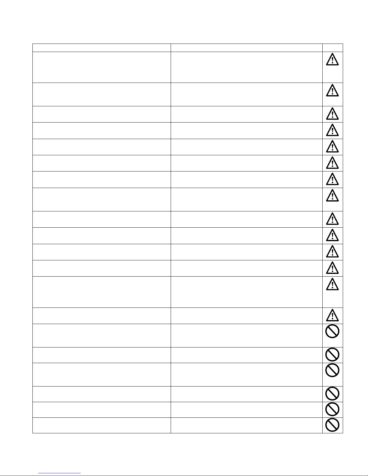
1. INFORMAZIONI IMPORTANTI
NORMA: RISCHIO:
Non effettuare operazioni che implichino l’apertura
dell’apparecchio.
Folgorazione per presenza di componenti sotto tensione.
Lesioni personali per ustioni per presenza di componenti
surriscaldati o per ferite per presenza di bordi e
protuberanze taglienti.
Non effettuare operazioni che implichino la rimozione
dell’apparecchio dalla sua installazione.
Folgorazione per presenza di componenti sotto tensione.
Lesioni personali per ustioni da raffreddamento per
fuoriuscita di gas dalle tubazioni scollegate.
Non avviare o spegnere l’apparecchio inserendo o
staccando la spina del cavo di alimentazione elettrica.
Folgorazione per danneggiamento del cavo, o della spina, o
della presa.
Non danneggiare il cavo di alimentazione elettrica. Folgorazione per presenza di fili scoperti sotto tensione.
Non lasciare oggetti sull’apparecchio.
Lesioni personali per la caduta dell’oggetto a seguito di
vibrazioni.
Non salire sull’apparecchio. Lesioni personali per la caduta dall’apparecchio.
Non salire su sedie, sgabelli, scale o supporti instabili
per effettuare la pulizia dell’apparecchio.
Lesioni personali per la caduta dall’alto o per cesoia mento
(scale doppie).
Non effettuare operazioni di pulizia dell’apparecchio
senza aver prima spento l’apparecchio, staccato la
spina o disinserito l’interruttore dedicato.
Folgorazione per presenza di componenti sotto tensione.
Non fare utilizzare l’apparecchio da bambini o
persone inesperte.
Danneggiamento dell’apparecchio per uso improprio.
Non dirigere il flusso dell’aria verso piani di cottura o
stufe a gas.
Esplosioni, incendi o intossicazioni per il flusso gas dagli
ugelli di alimentazione fiamme spente dal flusso d’aria.
Non inserire le dita nelle bocchette di uscita aria e
nelle griglie di aspirazione aria.
Folgorazione per presenza di componenti sotto tensione.
Lesioni personali per tagli.
Non bere l’acqua di condensa. Lesioni personali per intossicazione.
Nel caso si avverta odore di bruciato o si veda del
fumo fuoriuscire dall’apparecchio, togliere
l’alimentazione elettrica, aprire le finestre ed avvisare
il tecnico.
Lesioni personali per ustioni o inalazioni fumi.
Non effettuare operazioni che implichino la rimozione
dell’apparecchio dalla sua installazione.
Allagamenti per perdita acqua dalle tubazioni scollegate.
Non lasciare oggetti sull’apparecchio.
Danneggiamento dell’apparecchio o degli oggetti sottostanti
per la caduta dell’apparecchio a seguito del distacco dal
fissaggio.
Non utilizzare insetticidi, solventi o detersivi aggressivi
per la pulizia dell’apparecchio.
Danneggiamento delle parti in materiale plastico o verniciate.
Non utilizzare l’apparecchio per scopi diversi da
quello di un normale uso domestico.
Danneggiamento dell’apparecchio per sovraccarico di
funzionamento.
Danneggiamento degli oggetti indebitamente trattati.
Non fare utilizzare l’apparecchio da bambini o
persone inesperte.
Danneggiamento dell’apparecchio per uso improprio.
Non dirigere il flusso dell’aria verso oggetti di valore,
piante o animali.
Danneggiamento o deperimento per eccessivo freddo/
caldo, umidità, ventilazione.
Non usare il condizionatore per molto tempo in
condizioni di umidità superiore all’80%.
Danneggiamento oggetti per gocciolamento eccessiva
condensa dall’apparecchio.
Page 5
4
ITALIANO
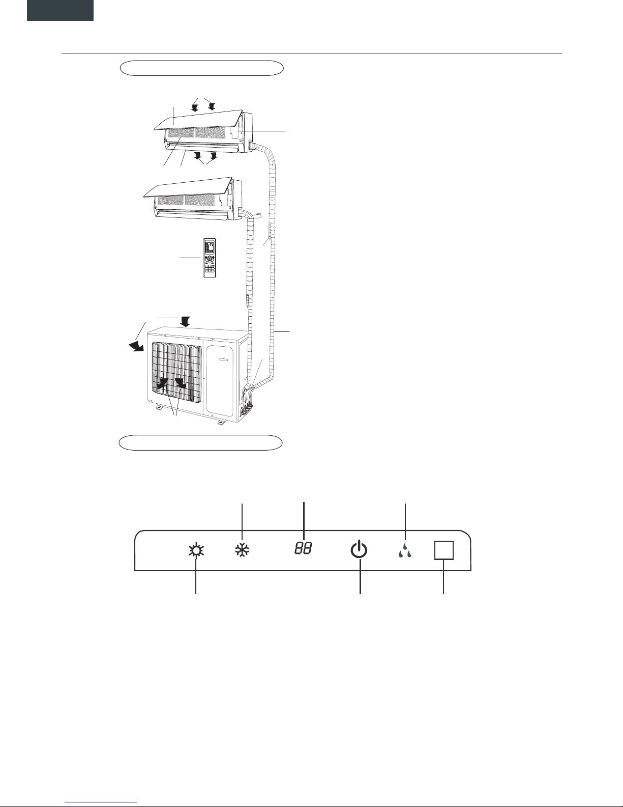
2. COMPONENTI
UNITA' INTERNA
UNITA' ESTERNA
(1) LED recivitore segnale
(2) Indicatore operation
Questo indicatore si illumina durante l'accensione del condizionatore.
(3) Indicatore di riscaldamento
Questo indicatore si accende durante l'operazione del condizionatore in modalità di riscaldamento.
(4) Indicatore di raffreddamento
Questo si illumina durante l'operazione del condizionatore in modalità di raffreddamento.
(5) Indicatore temperatura impostata
Questo indicatore visualizza la temperatura impostata durante il funzionamento del condizionatore.
(6) Indicatore di deumidificazione
Questo indicatore si illumina durante l'operazione del condizionatore in modalità di deumidificazione.
3. DISPLAY
(1)(2)(3)
(4) (5) (6)
(1) Ingresso aria
(2) Griglia frontale
(3) Pannello di controllo
(4) Uscita aria
(5) Alette flusso aria
(6) Filtri aria
(7) Ingresso aria
(8) Tubazioni connessione
(9) Scarico condensa
(10) Uscita aria
(11) Ingresso aria
(12) Telecomando
1230:
ON-OFF
23
FAN
°C
AUTO
O
PER
FAN
CLOCK
BLOW
TURBO S LEEP
TEMP
LIGHT
TIMER
OFF
TIMER
ON
IFEEL
MODE
(1)
(2)
(4)
(5)
(6)
(11)
(12)
(10)
(8)
(7)
(3)
(9)
Page 6
5
4. DESCRIZIONE TELECOMANDO
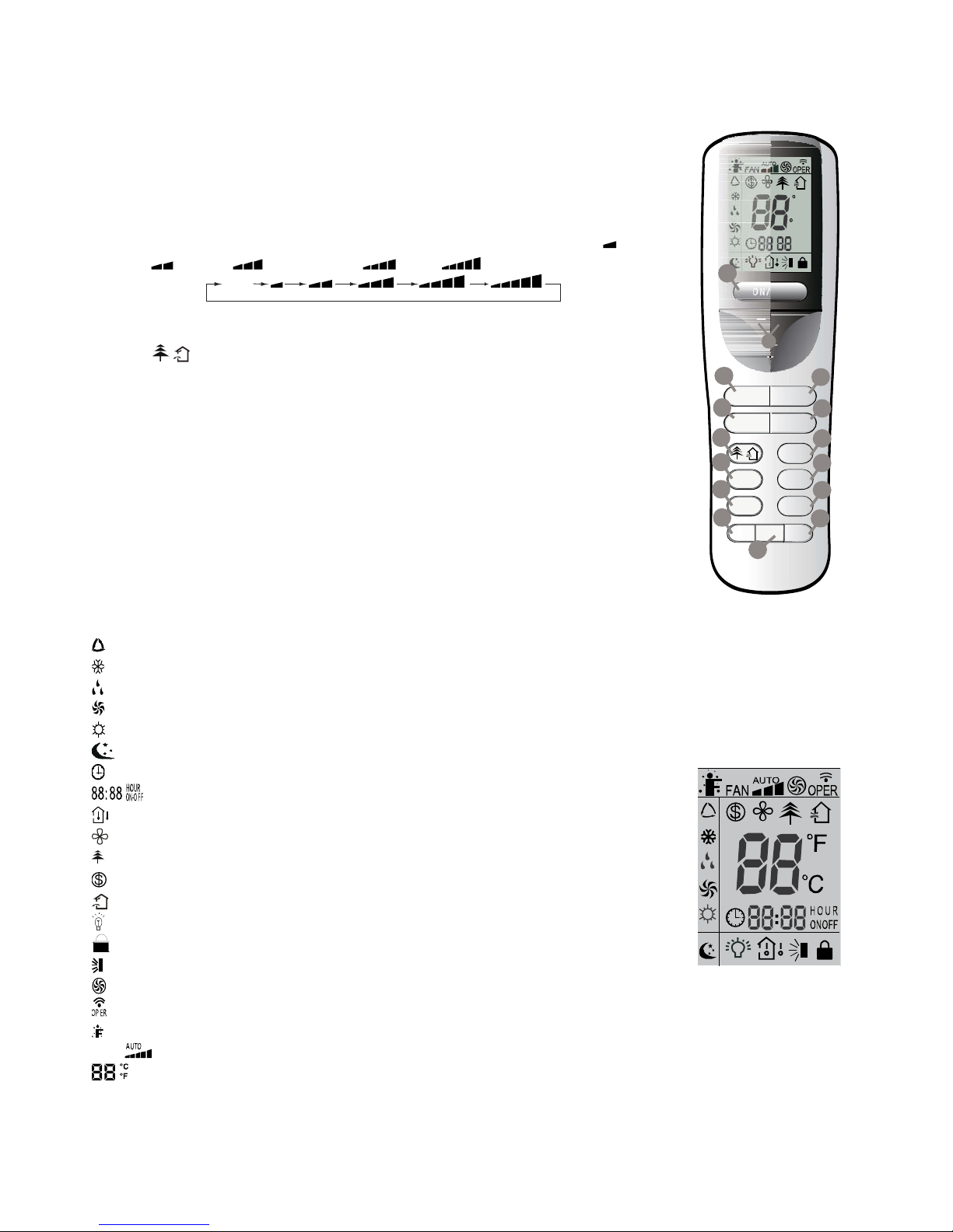
4.1. Descrizione funzioni tasti del telecomando
1) Tasto ON/OFF, consente di spegnere e accendere il condizionatore.
2) Tasti di regolazione consentono di regolare la temperatura ambiente interna e il timer: "+"
ne imposta l'aumento, "-" ne imposta la diminuzione.
3) Tasto MODE permette di selezionare la modalità di funzionamento: AUTO - COOL- DRY
- FAN – HEAT.
4) Tasto FAN permette di selezionare la velocità della ventilazione: Auto, Bassa (
), Bassa
– Media (
), Media ( ), Media – Alta ( ), Alta ( ).
Auto
5) Tasto SWING per attivare/disattivare il movimento automatico del deflettore d'aria.
6) Tasto I FEEL attiva/disattiva la funzione I FEEL.
(7) Tasto
/ permette di impostare la funzione di purificazione / rinnovo dell’aria.
8) Tasto SLEEP, usato per impostare/cancellare la modalità Sleep, indipendentemente dal
modo in cui sta operando il condizionatore.
9) Tasto TEMP permette di visualizzare sul display dell’unità la temperatura di set point o
ambiente.
10) Tasto CLOCK consente di impostare l’orario corrente.
11) 12) Tasti TIMER-ON / TIMER-OFF consentono di impostare l’orario di accensione /
spegnimento in automatico.
13) Tasto TURBO attiva/disattiva la modalità di raffreddamento e riscaldamento rapido.
14) Tasto LIGHT per accendere o spegnere il display dell’unità.
15) Tasto X-FAN consente di avviare / arrestare il ventilatore interno, questa funzione si
utilizza per asciugare i componenti dell'unità interna.
ONOFF/
-+
MODE FAN
SWING IFEEL
SLEEP
TEMP
TIMER-ON
CLOCK
TIMER- OFF
TURBO LIG HT
/
X-FAN
F
C
:
HOUR
ONOFF
14
4
3
13
6
15
12
10
8
7
11
9
1
5
2
4.2. Descrizione indicatori del display
: Indicatore modalità AUTO.
: Indicatore modalità di RAFFREDDAMENTO.
: Indicatore modalità di DEUMIDIFICAZIONE.
: Indicatore modalità di VENTILAZIONE.
: Indicatore modalità di RISCALDAMENTO.
: Indicatore modalità SLEEP.
: Indicatore OROLOGIO.
: Indicatore TIMER ON-OFF.
: Indicatore TEMPERATURA.
: Indicatore BLOW.
: Indicatore DEPURATORE ARIA.
: Indicatore funzione riscaldamento in 8°C.
: Indicatore modalità RINNOVO ARIA.
: Indicatore modalità LIGHT.
: Indicatore LOCK.
: Indicatore oscillazione deflettore.
: Indicatore modalità TURBO.
: LED conferma trasmissione segnale.
: Indicatore modalità I FEEL.
FAN
: Indicatore velocità ventilatore
: Indicatore visualizzazione temperatura.
DISPLAY
Page 7
6
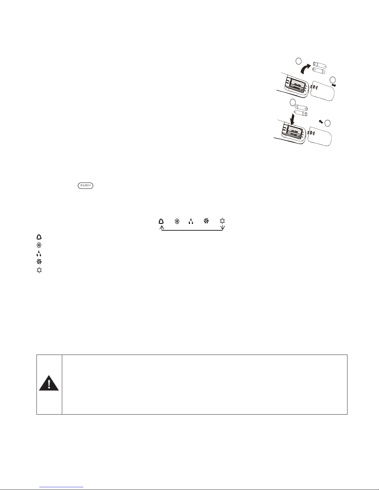
4.3. Come inserire/sostituire le batterie
Usare due batterie alcaline 1,5 V tipo AAA.
(1) Rimuovere il coperchio delle batterie facendolo scivolare nella direzione della freccia.
Rimuovere le batterie vecchie e inserire le nuove facendo attenzione ad allineare
correttamente le polarità (+) e (-).
(2) Chiudere il coperchio delle batterie facendolo scivolare nella sua posizione
Note:
- Non mettere insieme batterie nuove con vecchie o batterie di tipo differente. Ciò può
essere causa di malfunzionamento.
- Se non si usa il telecomando per un lungo periodo, le batterie devono essere tolte per
evitare danni causati da eventuali perdite.
- Le batterie vanno sostituite quando non si riceve alcun "bip" dall’unità interna o se
l’indicatore di trasmissione sul telecomando non si accende.
Posizionare il telecomando nell’apposito supporto fissato a muro (per assicurare la
trasmissione corretta del segnale).
1
2
3
4
4.4. Come utilizzare il telecomando per far funzionare l’unità
● ACCENSIONE SPEGNIMENTO DELL’UNITÀ
Premere il tasto
per accendere o spegnere l’unità.
● IMPOSTAZIONE DELLA MODALITÀ DI FUNZIONAMENTO
Premendo più volte il tasto Mode è possibile cambiare la modalità di funzionamento dell’unità. Sul display compare
l’indicazione della modalità di funzionamento selezionato:
→ → → →
: funzionamento completamente automatico
: funzione raffreddamento
: funzione deumidificazione
: funzionamento solo ventilazione
: funzione riscaldamento
Con la scelta della modalità AUTO, l’unità può operare in RAFFREDDAMENTO ed in RISCALDAMENTO in base alla
differenza di temperatura esistente tra la temperatura ambiente e la temperatura selezionata sul telecomando.
Quando viene scelta la modalità di raffreddamento, l’unità funziona con set di temperatura libero, abbassando la
temperatura in ambiente.
Quando viene scelto la modalità di deumidificazione, l’unità funziona, con set di temperatura libero, abbassando così
progressivamente la temperatura e l’umidità in ambiente. Nella modalità di deumidificazione il tasto FAN non è utilizzabile.
Quando viene scelto il programma di riscaldamento, l’unità funziona, con set di temperatura libero, alzando la temperatura
in ambiente. Quando viene scelta la modalità di ventilazione FAN, l’unità funziona senza set di temperatura, ventilando l’aria
dell’ambiente.
IMPORTANTE!
♦ Il ventilatore dell’unità si ferma al raggiungimento del valore di temperatura impostato per poi riattivarsi
automaticamente alla velocità minima per evitare fenomeni di stratificazione dell’aria in prossimità
dell’apparecchio.
♦ Selezionando la funzione RAFFREDDAMENTO, DEUMIDIFICAZIONE, il ventilatore potrebbe non avviarsi
subito perché presente la funzione ANTI-RISCALDAMENTO. Selezionando la funzione riscaldamento, il
ventilatore potrebbe non avviarsi subito perché presente la funzione ANTI-RAFFREDDAMENTO.
● IMPOSTAZIONE DEL DEFLETTORE
Per ottenere una distribuzione ottimale dell’aria, regolare la posizione del deflettore motorizzato avendo cura che il flusso
d’aria non investa direttamente le persone. Per il deflettore motorizzato agire nella modalità seguente:
Page 8
7
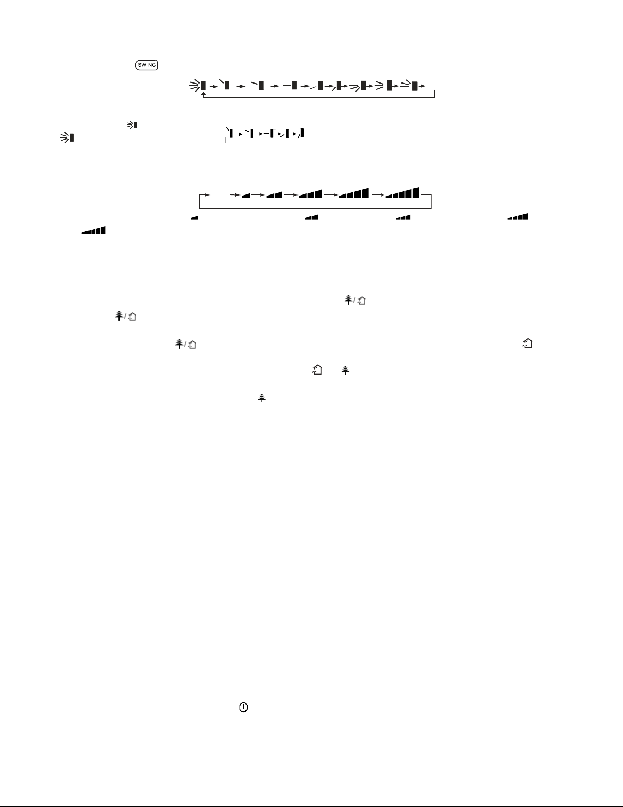
Premendo il tasto è possibile selezionare l’angolo di oscillazione come indicato sotto:
OF
F
Note: Questo telecomando è universale. Se il comando SWING non viene inviato all’unità, essa attiva l’oscillazione del
deflettore come
.
indica che il deflettore oscilla come:
● IMPOSTAZIONE DELLA VENTILAZIONE
Premendo più volte il tasto FAN è possibile impostare la velocità del ventilatore tra le tre disponibili, oppure attivare la
funzione AUTO. Sul display compare la modalità di funzionamento:
Auto
Velocità Auto, Velocità Bassa ( ), Velocità Bassa-Media ( ), Velocità Media ( ), Velocità Media-Alta ( ), Velocità
Alta (
).
● IMPOSTAZIONE DELLA FUNZIONE I FEEL
Premere il tasto I FEEL per attivare la funzione. In questo caso l'unità regola automaticamente la temperatura ambiente in
base alla temperatura rilevata dal sensore di temperatura posizionato nel telecomando.
Premere nuovamente questo tasto per annullare la funzione I FEEL.
● FUNZIONE DEPURAZIONE / CIRCOLAZIONE (RINNOVO) ARIA
Questo tasto
è usato per attivare/disattivare la modalità di depurazione / circolazione dell’aria quando il condizionatore
è in funzione.
Premendo una volta il tasto
la funzione di circolazione dell’aria si attiva ed il display visualizza l’indicatore “ ”.
Premendo per una seconda volta lo stesso tasto, le funzioni di depurazione e circolazione dell’aria si attivano
contemporaneamente ed il display visualizza gli indicatori “
” e “ ”. Premendo sullo stesso tasto per la terza volta, le
funzioni precedenti vengono disattivate. Premendo sullo stesso tasto per la quarta volta, la funzione di depurazione dell’aria
si attiva ed il display visualizza l’indicatore “
”. Per tornare al normale funzionamento del condizionatore, premere
nuovamente sullo stesso tasto.
● MODALITÀ SLEEP
La modalità "SLEEP" può essere impostata nel funzionamento di riscaldamento o di raffreddamento.
Questa funzione è utile per un ambiente più confortevole quando si va a dormire.
Nella modalità SLEEP:
- La velocità del ventilatore viene impostata sulla bassa.
- La temperatura impostata aumenta (diminuisce) di 1°C se il condizionatore funziona in modalità di raffreddamento
(riscaldamento). Quando la temperatura impostata varia con 2°C la macchina mantiene la temperatura fino all’ottava ora di
funzionamento in modalità “SLEEP”, per poi spegnersi automaticamente.
● FUNZIONE TEMP
Tasto TEMP permette di visualizzare sul display dell’unità la temperatura di set point, ambiente interna e ambiente esterna.
Note: La temperatura ambiente esterna viene visualizzata sul display solamente per alcuni modelli.
●
IMPOSTAZIONE DELL'OROLOGIO
Premere il tasto CLOCK per regolare l'orologio, utilizzare i tasti di regolazione ''+'' e ''-'' per impostare l'ora attuale.
- Una singola pressione del tasto ''+'' / ''-'', incrementa/decrementa l'orario di 1 minuto.
- Una pressione del tasto ''+'' / ''-'' per circa 2 secondi, incrementa/decrementa l'orario di 10 minuti.
●
IMPOSTAZIONE DEL TIMER
Utilizzare i tasti TIMER-ON / TIMER-OFF per impostare la programmazione oraria e quindi l’accensione e lo spegnimento
del condizionatore.
- Come impostare TIMER ON
Premere il tasto TIMER-ON per impostare la programmazione oraria dell’accensione del condizionatore.
1) Premere il tasto TIMER-ON, l’indicatore
scompare dal display mentre la scritta "ON" comincia a lampeggiare, dopo di
che usare i tasti ''+'' e ''-'' per impostare l’ora desiderata per l’accensione programmata del condizionatore:
- Premere il tasto ''+'' o ''-'' una volta per aumentare o diminuire l’orario di 1 minuto.
Page 9

8
- Premere il tasto ''+'' o ''-'' per una durata di 2 secondi per aumentare o diminuire l’orario di 10 minuti.
Nota: Se non regolate l'orario entro 10 secondi dopo aver premuto il tasto TIMER-ON, il telecomando abbandonerà
automaticamente la modalità TIMER ON.
2) Per confermare l'orario desiderato, premere il tasto TIMER-ON. Un “suono” può essere sentito, e la scritta “ON” smette di
lampeggiare.
3) Il display del telecomando visualizza l'orario attuale subito dopo l'impostazione del TIMER ON.
- Come cancellare TIMER ON
Premere di nuovo il tasto TIMER-ON, "un suono" può essere sentito dopodiché l'indicatore sparisce, e la modalità TIMER
ON verrà cancellata.
Nota: È analogo per impostare la modalità TIMER OFF per spegnere automaticamente il condizionatore all'ora impostata.
● MODALITÀ TURBO
- La modalità TURBO è usata per avviare o arrestare il raffreddamento e il riscaldamento rapido a massima velocità di
impostazione.
- In questa modalità TURBO, si possono regolare la direzione del flusso d'aria e il timer. Se si desidera uscire dalla modalità
TURBO, è sufficiente premere un tasto qualsiasi tra - TURBO, MODE, FAN o ON/OFF, il display ritorna alla modalità
originale.
● FUNZIONE LIGHT
Premere il tasto
LIGHT
per accendere la luce del display e si mostra l’indicatore LIGHT
. Premere nuovamente per
spegnerlo dopodiché l’indicazione
scompare dal display.
● FUNZIONE X-FAN
Se il tasto
X-FAN
viene premuto durante il funzionamento di RAFFREDDAMENTO o DEUMIDIFICAZIONE, il display
visualizzata l'indicatore
ed il ventilatore interno continua a girare per altri 10 minuti per asciugare l’interno dell’unità,
anche se essa è stata spenta.
Al momento dell’accensione dell’unità, la funzione X-FAN OFF è l’impostazione predefinita di fabbrica. X-FAN è disattiva nel
funzionamento in modalità AUTO, VENTILAZIONE o RISCALDAMENTO
● LOCK FUNCTION
Premendo contemporaneamente i tasti "+" e "-", il telecomando bloccherà l’ultima operazione impostata.
Tutti i tasti di comando vengono disattivati, incluso il tasto di accensione / spegnimento ON/OFF. Premendo nuovamente i
due tasti "+" e "-", si riattiveranno le funzioni dei tasti.
● FUNZIONE °C / °F
Premendo contemporaneamente i due tasti "MODE" e "-" ad unità spenta, si potrà scegliere se visualizzare la temperatura
in °C o °F.
● FUNZIONE “RISPARMIO ENERGIA”
Premere contemporaneamente i due tasti "TEMP" e "CLOCK" nel funzionamento in raffreddamento per attivare la funzione
di risparmio energetico ed il display del telecomando mostra la scritta "SE". Premere nuovamente la combinazione di due
tasti per annullare l’ultima funzione.
● FUNZIONE DI RISCALDAMENTO A 8°C
Premendo contemporaneamente i due tasti "TEMP" e "CLOCK" durante il funzionamento di riscaldamento, la modalità di
riscaldamento a 8°C (46°F) viene attivata ed il display del telecomando visualizza il simbolo
. Per annullare l’ultima
funzione; è sufficiente premere nuovamente la combinazione di tasti "TEMP" e "CLOCK".
Page 10
9
5. MANUTENZIONE
No
Household
Drai n
Clea ner
Attenzione
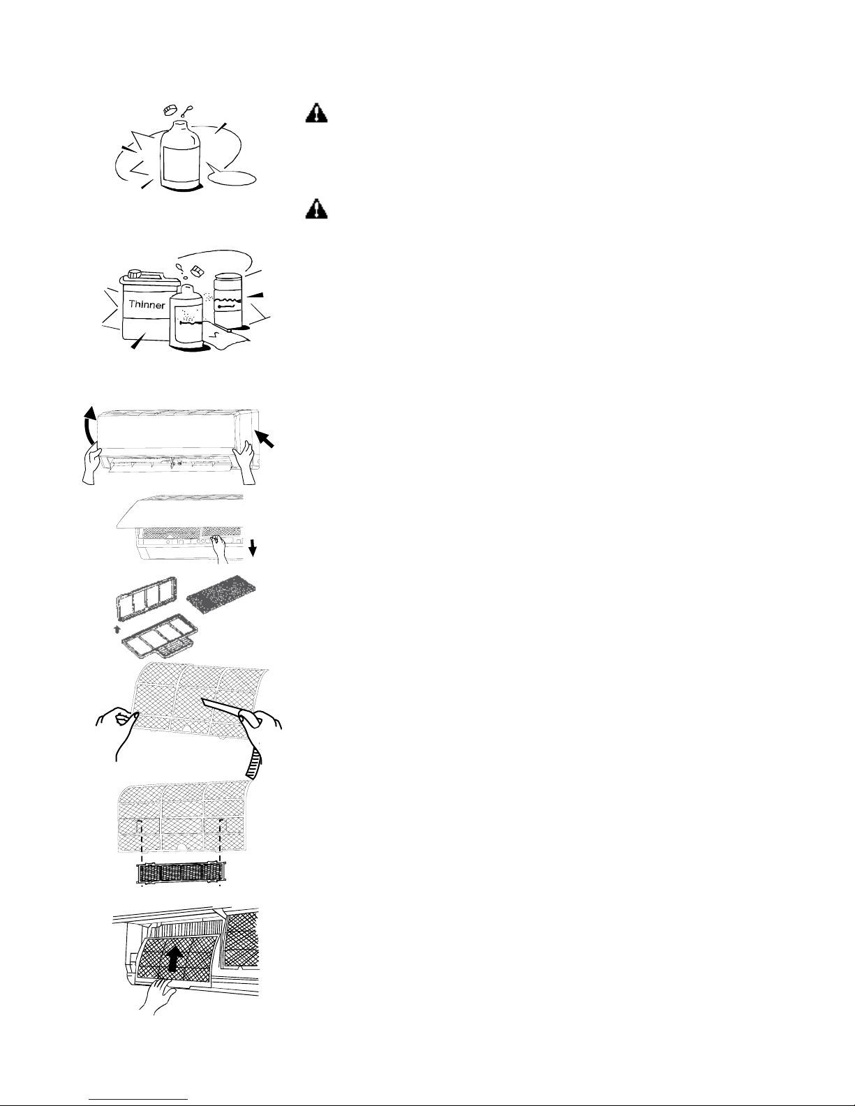
Quando si pulisce l'unità, assicurarsi che la spina di alimentazione elettrica e
il circuito siano spenti.
Pulizia dell’unità interna e del telecomando
Avvertenze
● Usare un panno asciutto per strofinare l'unità interna e il telecomando.
● Un panno inumidito con acqua fredda può essere usato per pulire l'unità esterna
se è veramente sporca.
● Mai usare un panno umido sul telecomando.
● Non utilizzare panni trattati chimicamente per pulire o lasciare tali materiali
sull'unità per molto. Questo può causare danneggiamenti o perdite di colore della
superficie dell'unità.
● Non usare diluenti, solventi, detergenti in polvere o solventi simili per la pulizia.
Questi possono causare la rottura o la deformazione della superficie plastica.
Pulizia del filtro
1) Sollevare dalle estremità il pannello frontale fino a quando non rimane bloccato.
Non sollevarlo ulteriormente dopo che si è fermato emettendo un “click”.
2) Prendere il filtro destro e sinistro per la maniglia, sollevarli e farli scivolare al di
fuori del loro supporto.
3) Tirarli verso il basso per rimuoverli completamente.
4) Rimuovere il filtro depuratore d’aria (carboni attivi e doppio polline).
5) Per lavare, prima di tutto rimuovere il filtro dalla griglia di supporto e immergerlo
in acqua con un detergente delicato per 20 minuti, e risciacquar lo dolcemente (non
strofinare). Quindi esporlo per l'asciugatura al sole per almeno 3 ore (mettere il lato
nero in alto).
6) Mettere il tessuto del filtro nella cornice del filtro dell'aria.
7) Mettere il filtro trattamento aria nel condizionatore con il lato nero in alto.
Nota: Pulire il filtro trattamento aria almeno una volta al mese e dopo 4-5 operazioni
di pulizia, il tessuto del filtro va sostituito.
8) Usare un aspirapolvere per rimuovere la polvere o lavare il filtro dell'aria.
Nota: Pulire il filtro dell'aria ogni due settimane, perché un filtro sporco può ridurre il
rendimento della macchina.
9) Inserire la parte superiore del filtro controllando che alle estremità entrino nelle
apposite corsie e spingere fino a quando non si blocca.
10) Posizionare la parte inferiore dei filtri nel loro alloggiamento e spingere i due
fermi dove c'è scritto PUSH per chiudere il pannello frontale saldamente.
Manutenzione
Se pensate di non usare l'unità per almeno un mese:
1) accendete la ventola per almeno mezza giornata per asciugare l'interno dell'unità;
2) fermare il condizionatore e staccare la corrente; 3) rimuovere le batterie dal
telecomando.
3. L'unità esterna richiede manutenzione e pulizia periodica. Non operare
personalmente, contattare il servizio tecnico.
Page 11

10
Verifiche prima del funzionamento.
● Verificare che l'impianto elettrico non sia mal funzionante o disconnesso.
● Verificare che il filtro dell'aria sia installato.
● Verificare che la presa e lo scarico dell'aria non siano bloccati dopo che il condizionatore è rimasto inutilizzato per lungo
tempo.
ATTENZIONE
● Non toccare le parti metalliche dell'unità quando si rimuove il filtro poiché ci si potrebbe ferire.
● Non usare acqua per pulire il condizionatore all'interno, potrebbe distruggere l'isolamento e causare un corto circuito.
● Quando si pulisce l'unità, assicurarsi che la spina e il circuito siano spenti.
6. OPERAZIONI E PRESTAZIONI
I seguenti eventi possono avvenire durante il funzionamento normale.
1. Protezione del condizionatore.
Protezione del compressore
- Il compressore impiegherà 3 minuti per partire dopo l'arresto.
Anti-aria Fredda
- L'unità è studiata per non emettere aria fredda in modalità di riscaldamento, quando lo scambiatore di calore dell'unità
interna è in una delle seguenti situazioni e la temperatura impostata non è stata raggiunta.
A) Quando è appena cominciato il riscaldamento.
B) Sbrinamento.
C) Bassa temperatura di riscaldamento.
Se l'unità esterna è coperta di brina, l'operazione di sbrinamento si attiverà automaticamente (per circa 4-10 minuti) per
mantenere gli effetti del riscaldamento.
- I ventilatori di entrambe le unità interna e esterna, si fermeranno durante l'operazione di sbrinamento.
- Durante l'operazione di sbrinamento, la condensa viene convogliata sul piatto del fondo dell'unità esterna.
2. Fumo generato dall'unità interna
- Può fuoriuscire del fumo dall'unità interna a causa della grande differenza di temperatura tra ingresso ed uscita dell'aria, in
moda lità raffreddamento, e l'alta umidità presente nell'ambiente da rinfrescare.
- Può generarsi fumo grazie all'umidità generata dal processo di sbrinamento quando il climatizzatore viene riavviato in
modalità riscaldamento.
3. Piccoli rumori del climatizzatore
Si può udire un rumore tipo "ss" causato dal flusso di refrigerante.
Si può udire un rumore tipo "zz" causato dalla dilatazione della plastica causata dalla variazione di temperatura.
All'accensione si recepisce un rumore dovuto all'apertura delle alette.
4. Della polvere fuoriesce dall'unità interna.
Ciò è normale quando il climatizzatore non è stato usato per un lungo periodo o durante il primo uso dell'unità.
5. Un particolare odore fuoriesce dall'unità interna.
Ciò è causato dall'unità interna che emette degli odori pervasi da materiale di costruzione, da mobilia, o da fumo.
6. Il climatizzatore cambia in modalità VENTILAZIONE dalla modalità di riscaldamento o raffreddamento (per i
modelli di raffreddamento e di riscaldamento soltanto).
Quando la temperatura interna raggiunge la temperatura d'impostazione, il compressore si arresterà automaticamente e
l'unità partirà modalità di ventilazione. Il compressore si riavvierà nuovamente quando la temperatura dell'interna aumenta
in modalità di raffreddamento o raggiunge la temperatura impostata in modalità di riscaldamento (per i modelli di
Page 12

11
raffreddamento e di riscaldamento soltanto).
7. Dell'acqua può apparire sulla superficie dell'unità interna in modalità di raffreddamento se l'umidità relativa è alta
(superiore all'80%).
Regolare il deflettore orizzontale al massimo dello scarico d'aria e scegliere la velocità alta di ventilazione.
8. In modalità di riscaldamento, il climatizzatore confluisce l'aria calda dall'unità esterna all'unità interna.
Quando la temperatura esterna diminuisce, il calore dell'aria ammessa dal climatizzatore diminuisce. Allo stesso tempo, il
carico calorifico del climatizzatore aumenta a causa della grande differenza tra le temperature esterna ed interna.
9. Funzione d'avviamento automatico
Un'interruzione di corrente durante il funzionamento spegnerà il climatizzatore.
Sui modelli senza dispositivo AUTORESTART, quando la corrente è ristabilita, l'indicatore di FUNZIONAMENTO dell'unità
interna inizia a lampeggiare. Per riavviare l'apparecchio, premere sul tasto ON/OFF del telecomando. Sui modelli muniti di
AUTORESTART, quando la corrente è ristabilita, l'apparecchio si riavvia automaticamente con i parametri di funzionamento
precedentemente impostati.
10. I lampi o l'utilizzo di un telefono portatile vicino all'apparecchio possono causare malfunzionamenti.
Staccare poi ricollegare l'apparecchio. Per riavviarlo, premere il tasto ON/OFF del telecomando.
Page 13
12
ITALIANO
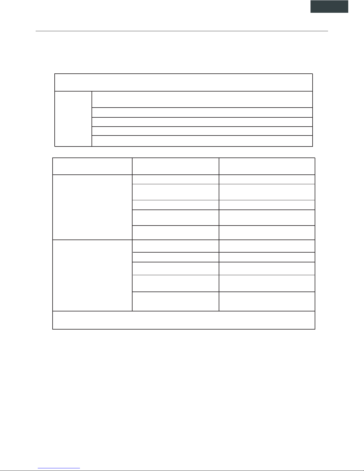
7. PROBLEMI E LORO CAUSE
Generalità
In caso di malfunzuionamento, disalimentare l'apparecchio e contattare il servizio assistenza più vicino.
L'indicatore di funzionamento, o qualsiasi altro indicatore, si mette a lampeggiare rapidamente (5
Hz) e nonostante lo sconnessione e la riconnessione dell'apparecchio, continua a lampeggiare.
I fusibili o l'interruttore saltano.
L'acqua o altro corpo sconosciuto è penetrato nel climatizzatore.
Il telecomando non funziona o il suo funzionamento non è normale.
Altra situazione anormale
Problema
Errore
Causa
Rimedio
L’unità non parte
Interruzione corrente Attendere il ripristino della corrente.
L'apparecchio è staccato
Verificare se la presa è correttamente
collegata
Il fusibile è saltato
Sostituire il fusibile
Le batterie del telecomando sono
scariche.
Sostituire le batterie
La programmazione è sbagliata
Attendre o annullare la programmazione.
L’unità non climatizza correttamente l’ambiente.
Temperatura impostata non adeguata.
Regolare correttamente la temperatura
Il filtro d’aria è otturato
Pulire il filtro d’aria
Sono bloccati l’ingresso o l’uscità
dell’aria.
Porte o finestre sono aperte
Chiudere le porte o le fenestre
Eliminare ciò che blocca il flusso dell’aria
prima di riavviare l'apparecchio.
I 3 minuti di protezione del compressore sono attivati.
Attendere
Nel caso di presenza dei problemi, si prega di contattare il fornitore locale o il servizio d’assistenza più vicino. Assicurarsi di dare le indicazioni precise che riguardino il tipo di guasto ed il modello dell'apparecchio.
Nota: Non cercare a riparare il climatizzatore da soli. Consultare sempre un centro d’assistenza autorizzato.
Page 14
13
8. INSTALLAZIONE
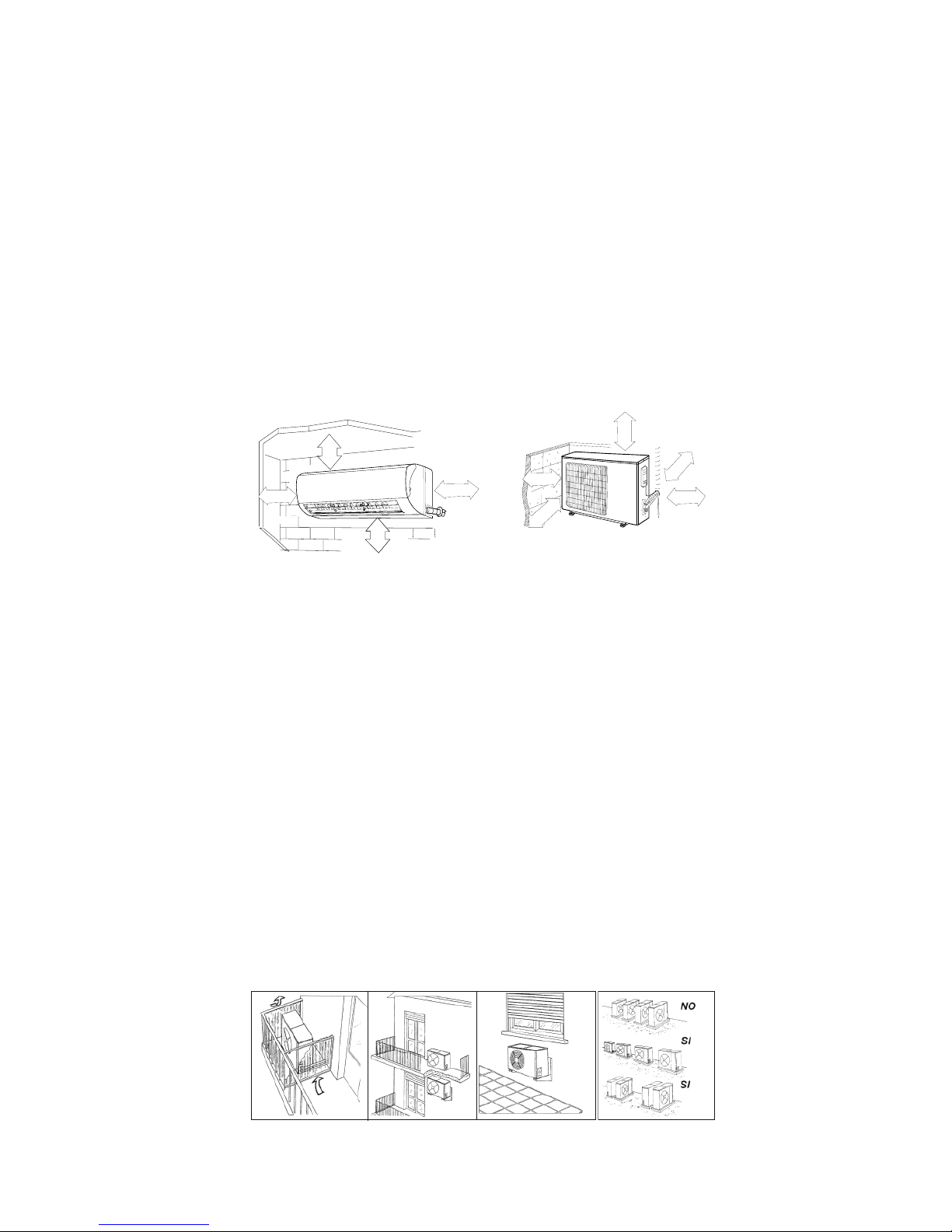
Unità interna
• Non esporre l'unità interna a calore o a vapore.
• Installare rispettando le distanze indicate, nella parte anteriore e intorno all'unità.
• Assicurarsi che lo scarico condensa funzioni.
• Non installare vicino ad una porta.
• Accertarsi che lo spazio sul lato destro e sinistro dell'unità sia maggiore di 12 cm.
• Prima di eseguire i fori accertarsi di controllare il passaggio di linee elettriche o tubazioni nella parete.
• Il tubo del refrigerante che collega le due unità non deve essere inferiore ai tre metri, onde evitare vibrazioni e rumore
eccessivo.
• L'unità interna dovrebbe essere installata sulla parete ad un'altezza di 2-3 m dal pavimento.
• L'unità interna dovrebbe essere installata ad una distanza minima di 15 cm dal soffitto.
• Se si prolunga il tubo che collega le due unità bisogna sempre aggiungere la quantità di refrigerante
corrispondente.
2
≤
2
5
0
c
m
0
2
0
≤
60 cm
≤
5
0
c
m
≤
1
5
c
m
≤ 15 cm
≤ 15 cm
≤
1
5
c
m
≤
1
5
c
m
≤
60 cm
Unità esterna
• Quando l’unità lavora in raffreddamento chiudere tende e finestre per evitare la luce solare diretta.
• Accertarsi che lo spazio nella parte posteriore dell'unità sia maggiore di 30 cm.
• La parte anteriore dell'unità dovrebbe avere più di 200 cm di spazio e le parti laterali dovrebbero avere più di 60 cm di
spazio.
• Non disporre piante o animali direttamente a ridosso del flusso d’aria.
• Tenere conto del peso del condizionatore e posizionarlo in un luogo che non rechi disturbo.
• Posizionare l’unita in un luogo in cui l’aria calda e il rumore non rechino disturbo ai vicini.
• Installare l'unità esterna su una base rigida per evitare l'aumento delle vibrazioni e del rumore.
• Posizionare lo scarico dell’aria in modo che il flusso non sia ostacolato in alcun modo.
Nel caso di forte vento, assicurarsi che il ventilatore funzioni correttamente posizionando l'unità longitudinalmente lungo una
parete o usando una schermatura.
• Specialmente nelle zone ventose, installare l'unità in modo che il ventilatore non sia ostacolato.
• Se l’apparecchio deve essere sospeso ad una parete esterna, il supporto deve rispettare le specifiche tecniche. Il muro
dove l’unità deve essere installata deve essere in mattoni o materiale di consistenza simile altrimenti deve essere rinforzato.
• Le staffe di sostegno devono essere stabili e resistenti.
• Assicurarsi che non vi siano ostacoli che impediscano il flusso dell’aria.
Page 15
14
ITALIANO
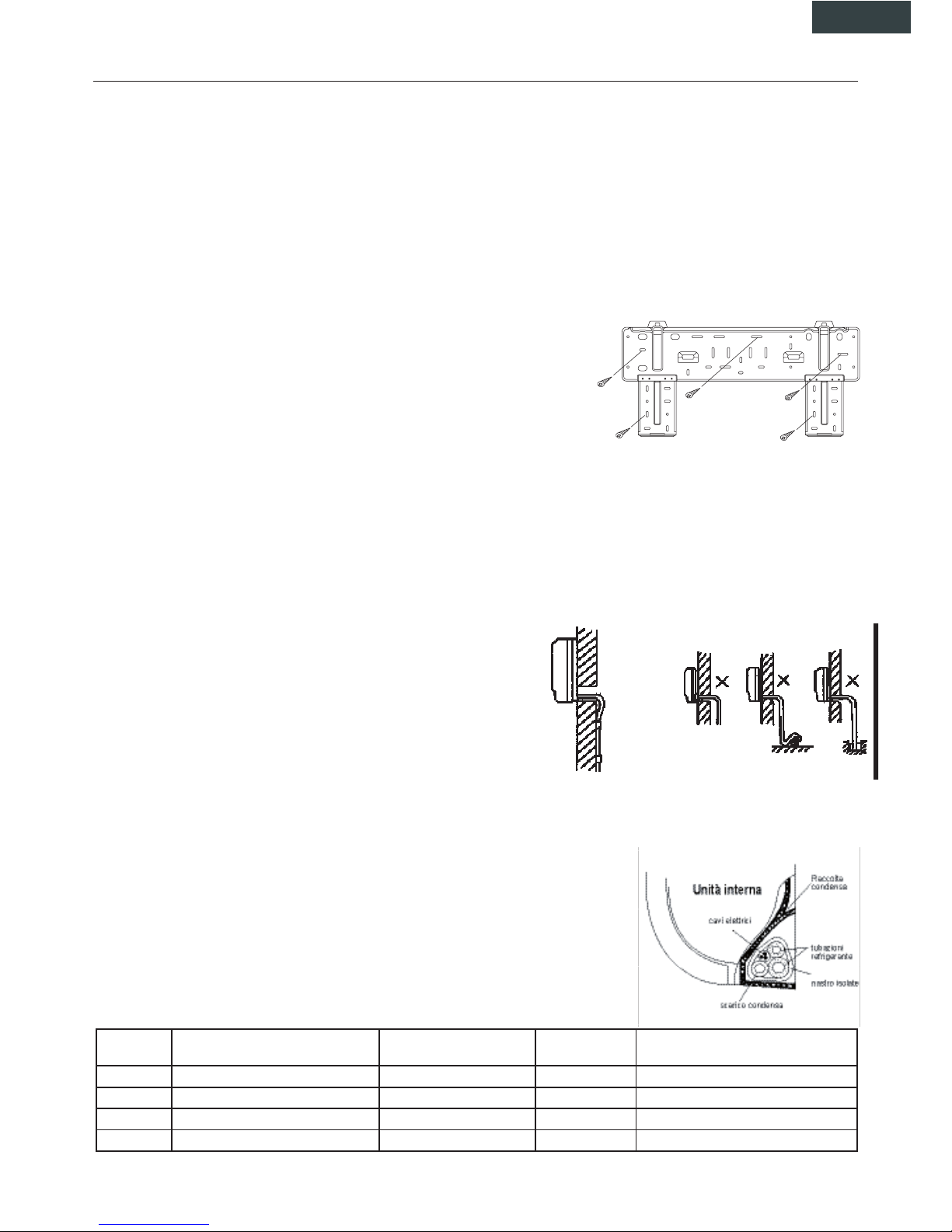
1. Fissaggio della piastra di sostegno
1. Instrallare la piastra di sostegno dell’unità interna orizzontalmente alla parete, e lasciare lo spazio necassario.
2. Se la parete è realizzata con mattoni o materiali simili, eseguire dei fori di 6 mm. Inserire dei tasselli appropriati.
3. Fissare la piastra di installazione sulla parete con otto (8) viti di tipo ”A”. Fissare la piastra di installazione sulla parete forando in
corrispondenza dei punti indicati sulla piastra. (Salvo indicazioni contrarie, le dimensioni sono in mm).
2. Foratura del muro per il passaggio delle tubazioni
1. Servendosi della piastra di installazione determinare la posizione dei fori per le tubazioni.
2. Prestare particolare attenzione quando si fora onde evitare ferimenti.
3. Installazioni delle tubazioni e dello scarico
1. Posizionare il tubo di scolo con la pendenza verso il basso. Non installare il tubo come illustrato.
2. Nel prolungare il tubo di scolo, isolare la parte di collegamento con del nastro iso lante, non lasciare che il tubo di scolo sia allentato.
Connessione delle tubazioni
1. Rimuove la piastra posteriore da destra o da a sinistra a seconda del lato scelto per
le tubazioni.
2. Dopo aver attraversato la parete con le tubazioni, piegarle a destra o a sinistra
mantenendo un adeguato spazio (43 mm) come mostrato in figura.
3. Fissare le tubazioni del refrigerante.
Installazione dell’unità interna
1. Far passare le tubazioni attraverso la parete.
2. Mettere la parte superiore dell'unita interna (ed il relativo gancio) a contatto con la piastra, quindi dopo aver spinto l'unità verso il
basso, muoverla per verificare se si è agganciata correttamente.
3. Per facilitare il collegamento delle tubazioni, sollevare l'unità interna e inserire un supporto in gomma tra l'unità e la parete.
Togliere tutto dopo aver connesso le tubazioni.
4. Appoggiare la parte inferiore dell'unità interna alla parete. Quindi, provare a muoverla per verificare se è fissata correttamente.
Installazione dell’unità esterna
Ancorare saldamente l'unità esterna con un bullone e con dadi da 10 o 8 mm
di diametro; orizzontalmente su un supporto rigido.
Montaggio del giunto di scolo.
Inserire la guarnizione nel gomito dello scolo, quindi inserire il giunto dello
scolo nel foro basso della vaschetta dell'unità esterna quindi ruotare di 90°
per fissarlo saldamente. Collegare il giunto con il prolungamento del tubo di
scolo (comprato a parte), nel caso che l'unità esterna subisca perdite d’acqua durante il riscaldamento.
Avvolgimento delle tubazioni
Avvolgere le tubazioni dello scarico e dei cavi elettrici come mostrato nella figura a lato.
Poiché la condensa che si forma durante il funzionamento viene raccolta nell’apposita bacinella, evitare di ostruirla.
AVVERTENZE
• Connettere prima l’unità interna e poi l’unità esterna e fissare saldamente le tubazioni.
• Non lasciare che le tubazioni escano dal retro dell’unità interna.
• Fare attenzione che lo scarico non sia allentato.
• Assicurarsi che le condutture ausiliarie siano state isolate.
• Assicurarsi che lo scarico defluisca correttamente. Fissare lo scarico alle altre tubazioni.
• Evitare che i cavi di alimentazione vengano a contatto con le tubazioni.
Modello Max. lunghezza consentita senza
aggiungere carica refrigerante (m)
Lunghezza tubazione (m) Dislivello H (m) Quantità refrigerante addizionale (g/m)
R410A
1 x 2 10 20 5 20
1 x 3 30 70 10 20
1 x 4 40 70 10 20
1 x 5 50 80 15 22
8. INSTALLAZIONE
Page 16
15
ITALIANO
8. INSTALLAZIONE
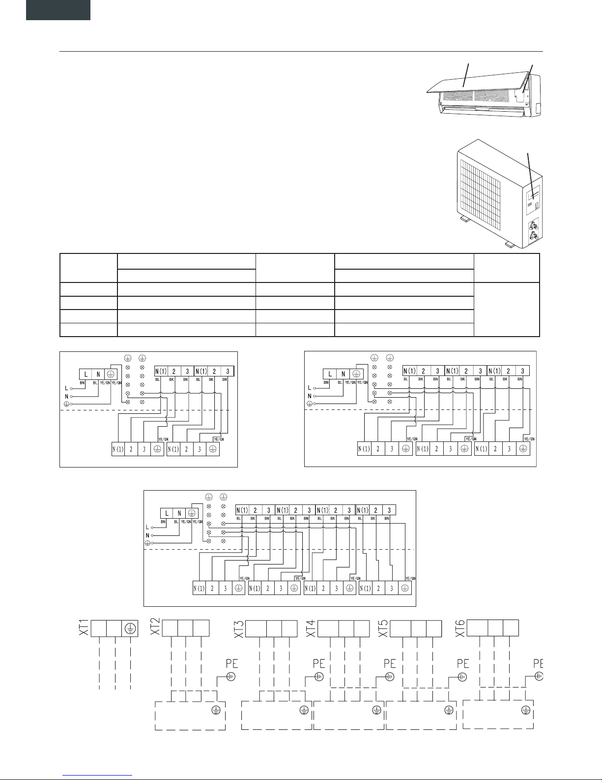
Connessioni elettriche
Collegare il cavo all'unità interna
1. Il cavo di collegamento dell'unità interna ed esterna dovrebbe essere di tipo H07RN-F.
2. Alzare il pannello dell'unità interna e rimuovere la vite, quindi rimuovere il coperchio.
3. Collegare i cavi secondo i loro contrassegni ai terminali.
4. Avvolgere i cavi dei terminali con nastro isolante, in modo che non si tocchino a vicenda.
Collegare il cavo all'unità esterna
1. Rimuovere il coperchio dell'unità esterna.
2. Collegare i cavi terminali in base ai numeri presenti sulla morsettiera dell’unità.
3. Per impedire l'ingresso di acqua isolare bene i cavi.
4. Fissare i cavi in modo che non vengano in contatto con parti elettriche o in metallo.
Specifiche Cavi
UNITA' INTERNA
Pannello frontale Morsettiera
Portello di accesso
morsettiera
UNITA' ESTERNA
Unità interne
Cavo collegamento interna-esterna
Unità esterne
Cavo collegamento alimentazione Alimentazione
principale
Sezione Sezione
2600 W 4 x 1,0 mm² 1 x 2 DC inverter 3 x 2,5 mm²
All'esterna
5300 W 4 x 1,0 mm² 1 x 3 DC inverter 3 x 4,0 mm²
5300 W 4 x 1,0 mm² 1 x 4 DC inverter 3 x 4,0 mm²
1 x 5 DC inverter 3 x 6,0 mm²
INDOOR A XT1
INDOOR A XT1
INDOOR A XT1
INDOOR UNITS
A B C D
INDOOR B XT1 INDOOR C XT1 INDOOR D XT1
INDOOR UNITS A B C
OUTDOOR UNIT
OUTDOOR UNIT
OUTDOOR UNIT
INDOOR B XT1 INDOOR C XT1
INDOOR UNITS A B
INDOOR B XT1
1 x 2 MULTI DC INVERTER 1 x 3 MULTI DC INVERTER
1 x 5 MULTI DC INVERTER
L N
2 3
N(1)
2 3
N(1)
2 3
N(1)
2 3
N(1)
2 3
N(1)
2 3
N(1)
2 3 2 3 2 3 2 3
N(1)
N(1)
N(1) N(1)
INDOOR UNIT A INDOOR UNIT B INDOOR UNIT C INDOOR UNIT D
INDOOR UNIT E
POWER / ALIMENTAZIONE
TO OUTDOOR UNIT
1 x 4 MULTI DC INVERTER
Page 17
16
ITALIANO
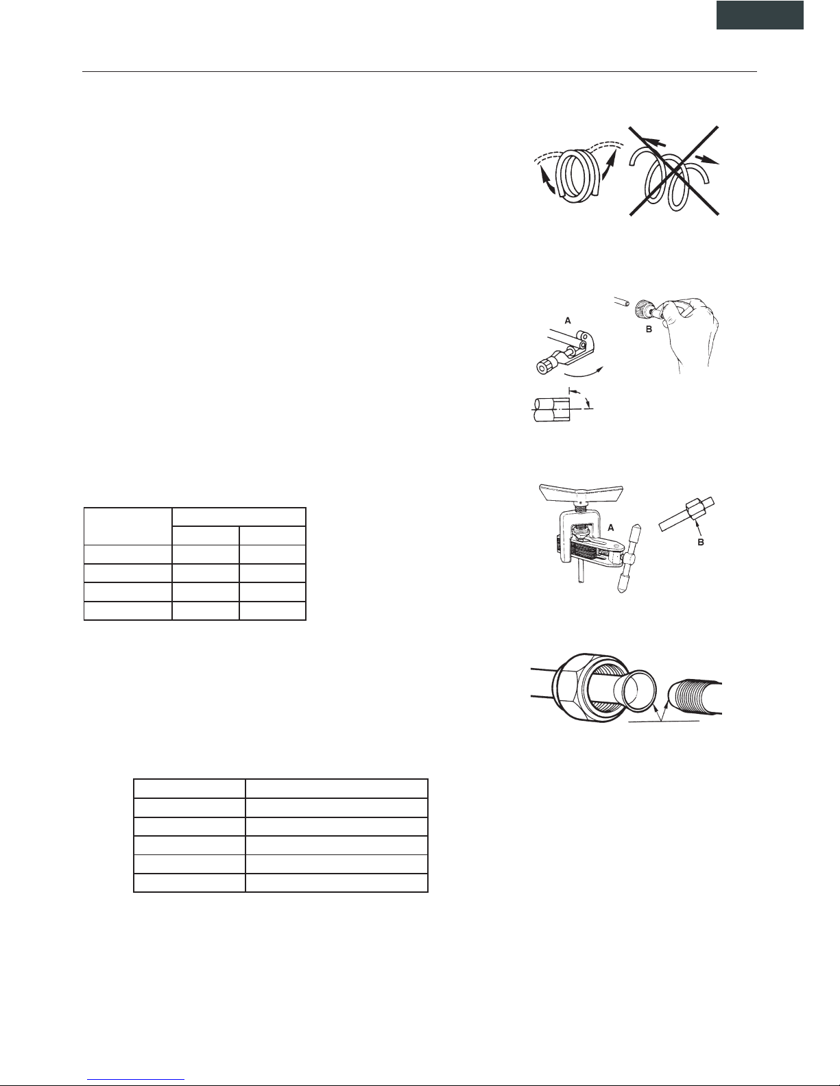
Installazione delle tubazioni per il refrigerante
1. Cartellatura
La causa principale di perdite di refrigerante è dovuta ad un difetto nella cartellatura. Effettuare le cartelle in modo corretto rispettando le seguenti indicazioni:
A: Tagliare i tubi ed il cavo.
1. Utilizzare tubi con misure adeguate all'unità installata.
2. Misurare la distanza fra l'unità interna ed esterna.
3. Tagliare i tubi ad una lunghezza leggermente maggiore della distanza misurata.
4. Tagliare il cavo 1.5 m più lungo della lunghezza del tubo.
B: Rimozione della bava
1. Rimuovere completamente tutte le bave dalla sezione trasversale del tubo.
2. La lavorazione deve essere eseguita con l’estremità da lavorare verso il basso in
modo che le bave non cadano dentro al tubo.
C: Collocazione del dado
Rimuovere i dadi fissati sull’unità interna ed esterna, infilarli sul tubo ed eseguire la
cartellatura e la rimozione delle bave come precedentemente indicato. (Non è possibile fissarli dopo la cartellatura).
D: Cartellatura
Fissare saldamente il tubo di rame con un dado della dimensione indicata nella
tabella.
Diam. E (mm) A(mm)
Max. Min
Φ6,35 1,3 0,7
Φ9,52 1,6 1
Φ12 1,8 1
Φ16 2 1
Fissaggio del collegamento
• Allineare i tubi.
• Stringere sufficientemente il dado e stringerlo con due chiavi come indicato in
figura.
PRECAUZIONI
• Una coppia di torsione eccessiva può rompere il dado.
8. INSTALLAZIONE
Diam. Est. (mm) Coppia di torsione (N.m)
Φ 6 15 ~ 20
Φ 9,52 31 ~ 35
Φ 12 50 ~ 55
Φ 16 60 ~ 65
Φ 19 70 ~ 75
Page 18
17
ITALIANO
8. INSTALLAZIONE
Eliminazione dell'aria
L'aria e l'umidità nel sistema refrigerante possono causare effetti indesiderati come indicato qui sotto:
• Aumento della pressione nel sistema.
• Aumento della corrente assorbita.
• Diminuzione dell’efficienza del refrigerante.
• L'umidità nel circuito refrigerante può congelare ed ostruire la tubazione capillare.
• L'acqua può corrodere le parti del sistema di refrigerazione.
Di conseguenza il gruppo interno e i tubi posti tra gruppo interno ed esterno devono
essere collaudati per perdite e spurgati per rimuovere elementi non condensanti e umidità dal sistema.
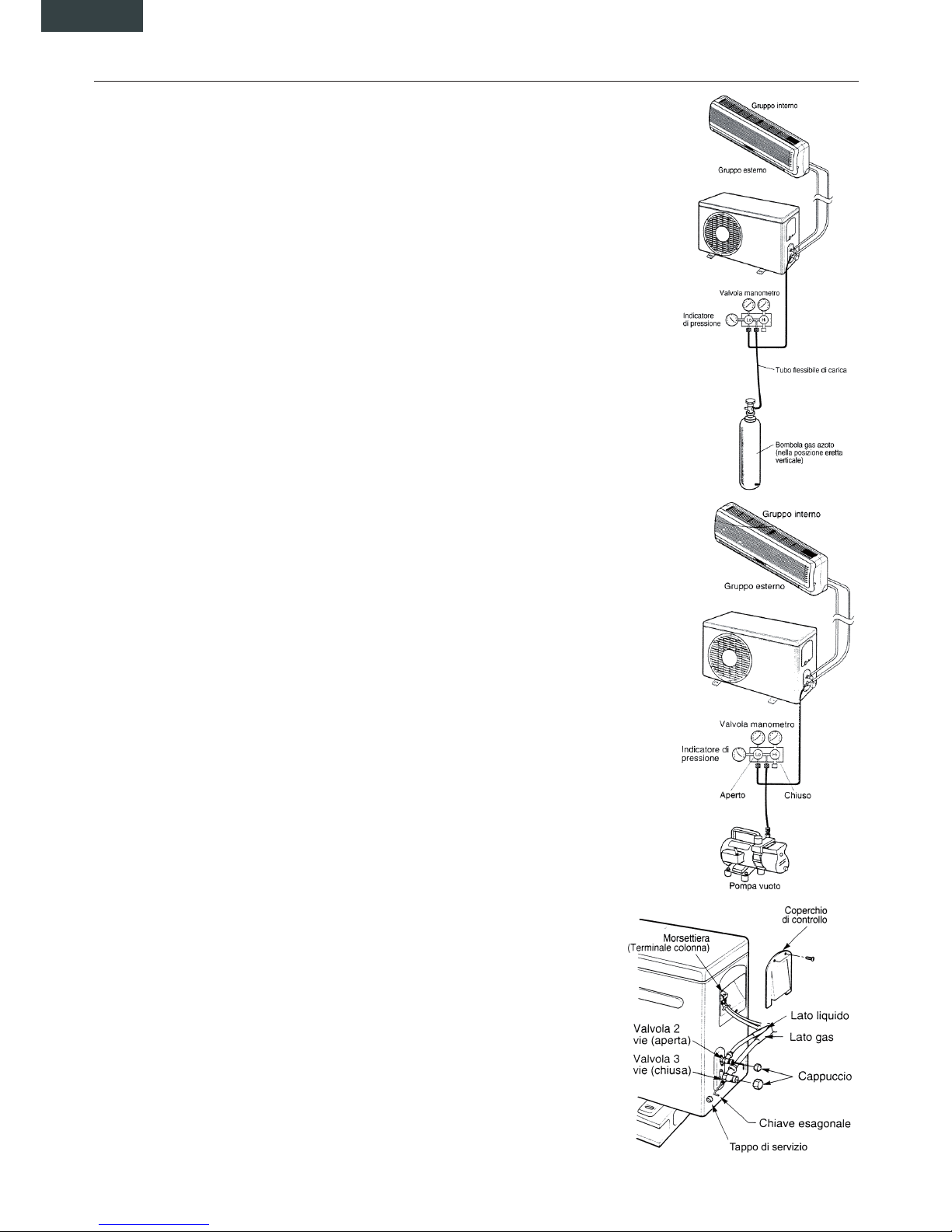
Eliminazione dell'aria con la pompa del vuoto
• Preparazione:
Verificare che ciascun tubo (sia i tubi laterali del gas che del liquido) tra gruppo interno e
gruppo esterno siano stati collegati nel modo corretto e che tutti i cablaggi necessari al
collaudo siano stati effettuati. Rimuovere i cappucci delle valvole di servizio sia dai lati
gas che liquido sul gruppo esterno. Prendere nota del fatto che a questo punto entrambi
le valvole del gas e del liquido rimangono chiuse.
• Lunghezza del tubo e relativa quantità di refrigerante, per una corretta carica verifica
re il valore di surriscaldamento. I valori della tabella sono indicativi.
• Quando si cambia posto all’unità, realizzare lo spurgo con la pompa del vuoto. Assi
curarsi che il refrigerante all’interno del condizionatore sia sempre stato liquido.
Evacuazione
Collegare l’estremità del tubo flessibile di carica alla pompa del vuoto per evacuare le
tubature dell’unità interna. Verificare che la manopola “LO” della valvola del manometro
sia aperta. Poi far funzionare la pompa del vuoto. Il tempo di funzionamento varia a
seconda della lunghezza dei tubi e della capacità della pompa. Quando viene raggiunto
il vuoto desiderato, chiudere la manopola “LO” della valvola del manometro e fermare la
pompa del vuoto.
In conclusione, usando una chiave per valvole di servizio, ruotare lo stelo della valvola
del lato del liquido in senso antiorario per aprirla completamente. Ruotare lo stelo della
valvola del lato gas in senso antiorario per aprirla completamente.
Allentare il tubo flessibile di carica collegato alla presa di servizio del lato gas per scaricare la pressione, poi rimuovere il tubo. Rimettere il dado di copertura della valvola gas
e della presa di servizio e stringere bene con una chiave regolabile. Questa procedura
è molto importante per evitare perdite dall’impianto. Rimettere i cappucci delle valvole
di servizio sia dal lato gas che da quello liquido e stringere bene. Questo completa la
procedura di spurgo dell’aria con la pompa del vuoto, assicurarsi quindi che tutti i tubi
siano collegati in maniera corretta e che le valvole di servizio dei lati gas e liquido siano
completamente aperte.
Svuotamento
Questa procedura viene effettuata quando il gruppo deve essere spostato o viene effettuata l’assistenza al circuito refrigerante.
Svuotamento significa raccogliere tutto il refrigerante nel gruppo esterno senza che si
verifichino perdite.
Attenzione
Assicurarsi di eseguire la procedura di svuotamento con il gruppo in modalità Freddo.
Procedura di recupero
• Collegare un manometro di bassa pressione con un tubo alla presa di servizio della
valvola gas.
• Aprire a metà la valvola gas e svuotare l’aria dalla tubazione del manometro usando
il gas refrigerante.
• Chiudere completamente la valvola liquido.
• Accendere la macchina in modalità raffreddamento.
• Quando la pressione del manometro si porta tra 1 e 0,5 kg/cm 2G (tra 14,2 e 7,1
P.S.G.I.) chiudere completamente la valvola gas e spegnere velocemente il climatiz
zatore. Si è così effettuato il recupero completo del refrigerante dell’unità esterna.
Page 19
18
9. PROVA DI FUNZIONAMENTO
• Il test deve essere eseguito solo dopo aver completato l’installazione.
• Si prega di controllare i seguenti punti prima di eseguire il test.
• Unità interna ed esterna devono essere installate correttamente.
• Tubazioni e cavi elettrici devono essere collegati correttamente.
• Test di pressione delle tubazioni.
• Lo scarico condensa funziona regolarmente.
• L’isolamento termico è stato eseguito correttamente.
• La messa a terra è stata eseguita correttamente.
• La lunghezza delle tubazioni e la carica di refrigerante sono state controllate.
• La tensione di alimentazione corrisponde a quella di progetto per il condizionatore.
• Ingresso ed uscita dell’aria delle unità interne ed esterne non sono ostruite.
• Le valvole lato gas e lato liquido sono aperte.
• Il condizionatore è stato pre-riscaldato dando tensione.
♦ Test operation
■ Impostare con il telecomando il condizionatore in modalità raffreddamento, e controllare i seguenti punti come indicato
nella parte d’uso di questo manuale. Se accade qualche malfunzionamento, risolverlo servendosi delle indicazioni del
capitolo “MALFUNZIONAMENTI” di questo manuale.
1) Unità interna
a) Verificare se accensione e spegnimento dal telecomando avvengono correttamente.
b) Verificare se i tasti del controllo remoto sono tutti operativi.
c) Verificare se i deflettori od alette si muovono regolarmente.
d) Verificare se la temperatura interna è regolata correttamente.
e) Verificare se gli indicatori sul ricevitore funzionano.
f) Verificare se il tasto manuale funziona correttamente.
g) Verificare se lo scarico condensa avviene con regolarità.
h) Verificare se ci sono vibrazione o rumori strani durante l’operazione.
j) Verificare se la capacità di riscaldamento è adeguata.
2) Unità esterna
a) Verificare la presenza di eventuali rumori o vibrazioni fuori norma.
b) Verificare se ci sono perdite di gas refrigerante.
CAUTELA
La funzione di protezione del condizionatore impedisce l’accensione immediata dello stesso dopo averlo
spento. Il condizionatore all’intervento della protezione potrà essere riavviato dopo circa 3 minuti dal suo
spegnimento.
Page 20

19
ENGLISH
CONTENTS
1. IMPORTANT INFORMATIONS........................................................................................................................... 20
2. COMPONENTS ................................................................................................................................................... 21
3. DISPLAY .............................................................................................................................................................. 21
4. REMOTE CONTROLLER DESCRIPTION.......................................................................................................... 22
4.1. Description of functions of remote controller keys ........................................................................................... 22
4.2. Name and functions of the display indicators .................................................................................................. 22
4.3. How to insert the batteries................................................................................................................................ 23
4.4. How to use the remote control to operate the unit........................................................................................... 23
5. MAINTENANCE................................................................................................................................................... 26
6. OPERATIONS AND PERFORMANCES............................................................................................................. 27
7. TROUBLES AND CAUSES................................................................................................................................. 29
8. INSTALLATION ................................................................................................................................................... 30
9. TEST OPERATION ............................................................................................................................................. 35
Page 21
20
1. IMPORTANT INFORMATIONS
NORM: RISk:
Do not perform operations that involve opening the appliance.
Electrocution from live components. Personal injury from
burns due to overheated components or wounds caused by
sharp edges or protrusions.
Do not perform operations that involve removing the appliance
from its place of installation.
Electrocution from live components. Personal injury from
burns due to cooling gases leaking from disconnected piping.
Do not start or stop the appliance by simply plugging it into or
out of the electricity mains.
Electrocution from a damaged cable or plug or socket.
Do not damage the power supply cable. Electrocution from live unsheathed wires.
Do not leave anything on top of the appliance.
Personal injury from an object falling off the appliance
following vibrations.
Do not climb onto the appliance. Personal injury due to the appliance falling.
Do not climb onto chairs, stools, ladders or unstable supports
to clean the appliance.
Personal injury from falling from a height or from cuts
(stepladders shutting accidentally).
Do not attempt to clean the appliance without first turning it off
and unplugging it or switching the dedicated switch off.
Electrocution from live components.
Do not allow children or inexperienced people to use the
appliance.
Damage to the appliance due to improper use.
Do not direct the air flow towards gas hobs or gas stoves.
Explosions, fi res or intoxication from the discharge of gas
leaking from the burner nozzle once the air flow has put the
flame out.
Do not place your fingers in the air outlets or in the air inlet
grilles.
Electrocution from live components. Personal injury from cuts.
Do not drink the condensation water. Personal injury from poisoning.
Should the smell of burning be detected or smoke exit the
appliance, disconnect it from the electricity supply, open all
windows and call in the technician.
Personal injury from burns or smoke inhalation.
Do not perform operations that involve removing the appliance
from its place of installation.
Flooding due to water leaking from disconnected piping.
Do not leave anything on top of the appliance.
Damage to the appliance or any objects underneath it due to
the appliance falling off from its place of installation.
Do not use any insecticides, solvents or aggressive detergents
to clean the appliance.
Damage to the plastic and painted parts.
Do not use the appliance for any use other than normal
domestic use.
Damage to the appliance due to operation overload. Damage
to objects treated inappropriately.
Do not allow children or inexperienced people to use the
appliance.
Damage to the appliance due to improper use.
Do not direct the air flow towards valuable articles, plants or
animals.
Damage or perishing due to excessive cold/heat, humidity,
ventilation.
Do not use the air conditioning unit for extended periods of
time in conditions of more than 80% humidity.
Damage to objects due to excessive dripping of condensation
from the appliance.
Page 22
21
ITALIANO
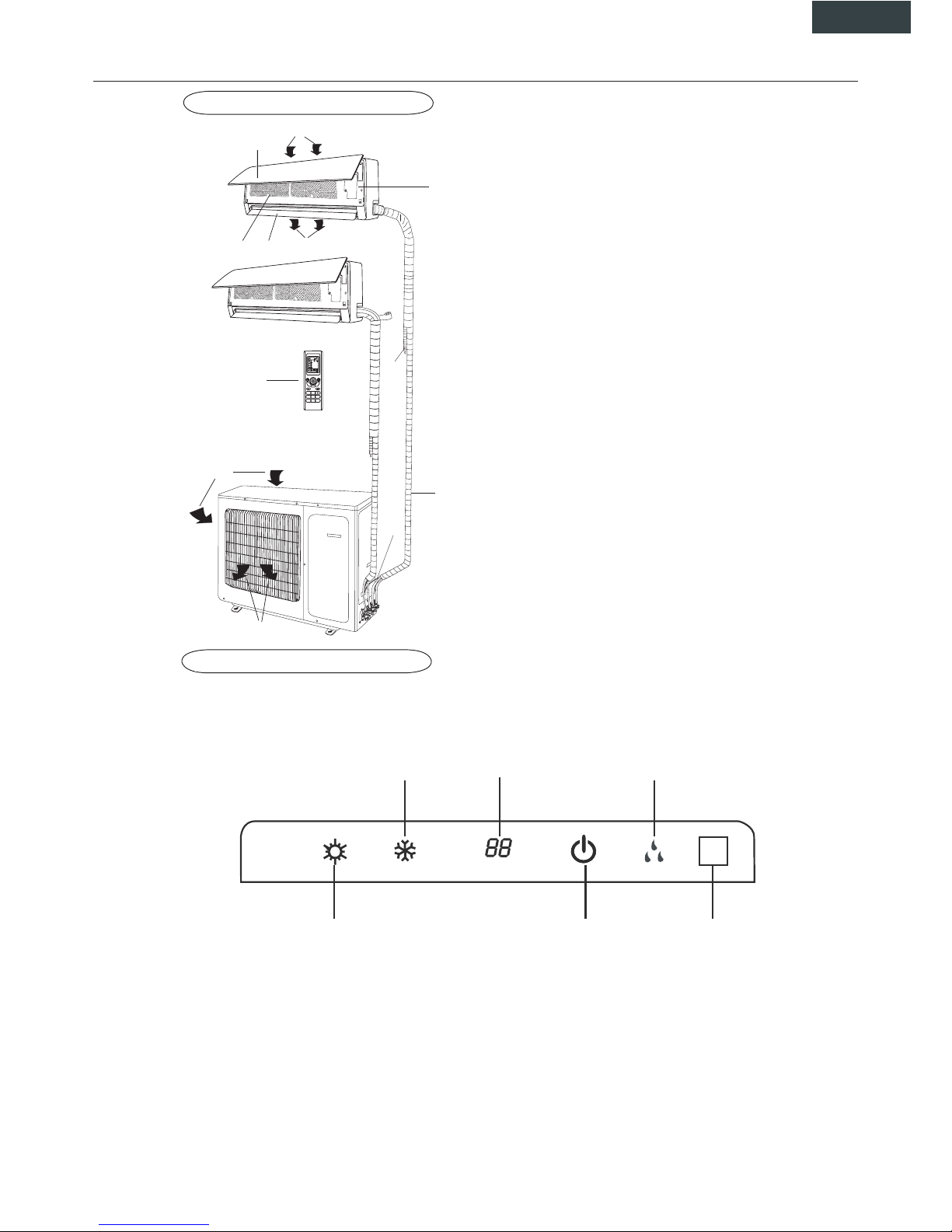
2. COMPONENTS
INDOOR UNIT
OUTDOOR UNIT
3. DISPLAY
1230:
ON-OFF
23
FAN
°C
AUTO
O
PER
FAN
CLOCK
BLOW
TURBO S LEEP
TEMP
LIGHT
TIMER
OFF
TIMER
ON
IFEEL
MODE
(1)
(2)
(4)
(5)
(6)
(11)
(12)
(10)
(8)
(7)
(3)
(9)
(1) Aifr intake
(2) Front panel
(3) Control panel
(4) Air outlet
(5) Air flow louver
(6) Air filter
(7) Aifr intake
(8) Connecting pipe
(9) Drain
(10) Air outlet
(11) Air intake
(12) Remote controller
(1) LED signal receiver
(2) Operation indicator
This indicator flashes after power is on and illuminates when the unit is in operation.
(3) Heating indicator
This indicator illuminates during the operation in heating mode.
(4) Cooling indicator
This indicator illuminates during the operation in cooling mode.
(5) Setting temperature indicator
It displays the setting temperature during the operation of the air condizioner.
(6) Dehumidification indicator
It illuminates during the operation in dehumidification mode
(1)(2)(3)
(4) (5) (6)
Page 23
22
4. REMOTE CONTROLLER DESCRIPTION
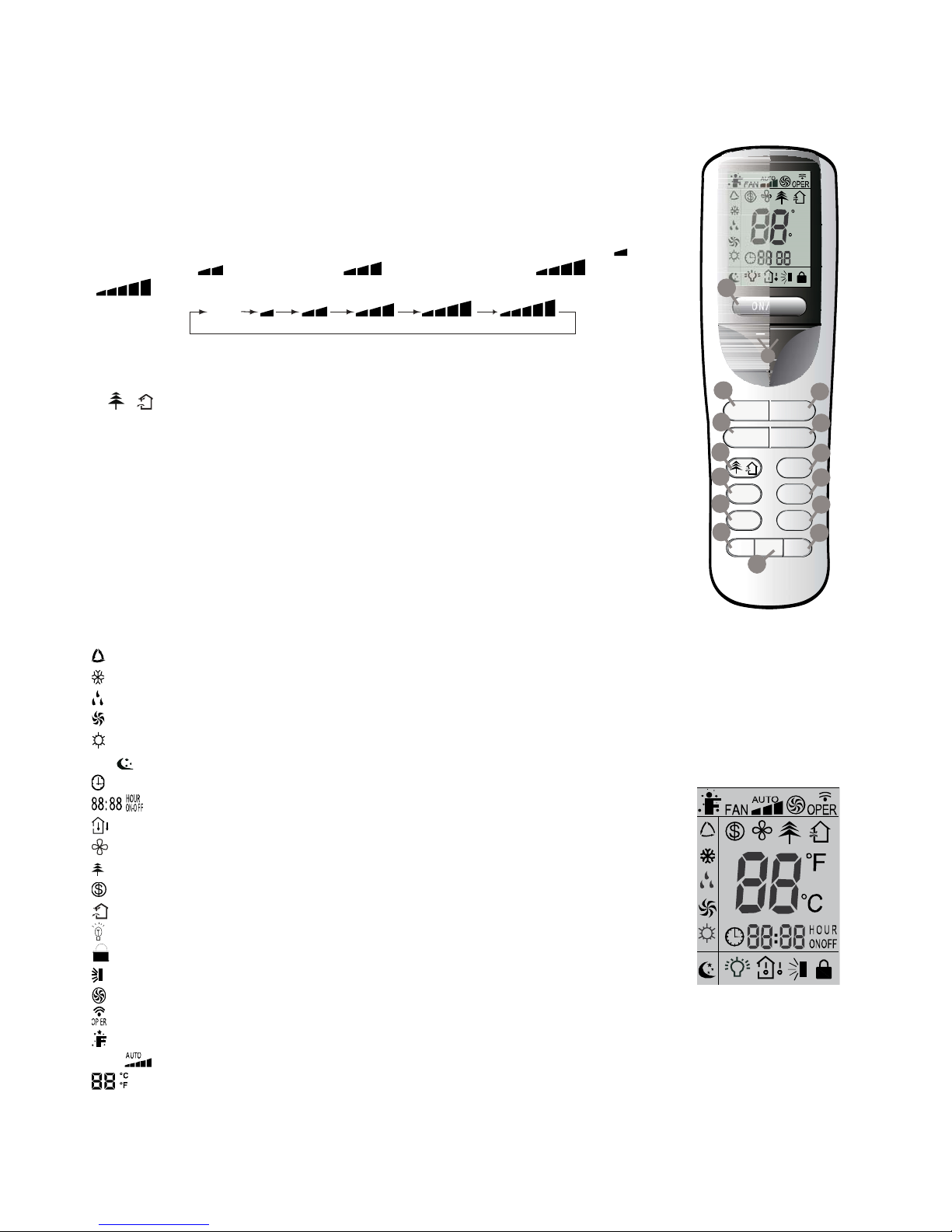
4.1. Description of functions of remote controller keys
1) ON/OFF key to turn the air conditioner on and off.
2) ADJUSTING keys to adjust ambient temperature and the timer: "+" increasing, "-"
decreasing.
3) MODE key to select the operating mode: AUTO - COOL- DRY - FAN - HEAT:
4) FAN key to set the fan speed in the sequence that goes from Auto, Low (
), Low-
Medium speed (
), Medium speed ( ), Medium-High speed ( ), High speed
(
).
Auto
5) SWING key used to set swing angle.
6) I FEEL key to enable/disable the IFEEL mode.
7)
/ key to set HEALTH / AIR function for air cleaning / for air change.
8) SLEEP key to set/cancel the Sleep mode regardless of the operating mode of the
conditioner.
9) TEMP key, press it to show the set point temperature on the unit’s display.
10) CLOCK key is used to set the current time.
11) 12) TIMER selection buttons. Press it to set auto-off/auto-on timer.
13) TURBO key used to enable/disable the rapid cooling or heating mode.
14) LIGHT key used to turn on or off the unit’s display.
15) X-FAN key press it to begin/stop indoor fan which is used to dry the components.
ONOFF/
-+
MODE FAN
SWING IFEEL
SLEEP
TEMP
TIMER-ON
CLOCK
TIMER- OFF
TURBO LIG HT
/
X-FAN
F
C
:
HOUR
ONOFF
14
4
3
13
6
15
12
10
8
7
11
9
1
5
2
4.2. Name and functions of the display indicators
: AUTO mode indicator
: COOL mode indicator
: DRY mode indicator
: FAN mode indicator
: HEAT mode indicator
: SLEEP mode indicator
: CLOCK indicator
: TIMER ON-OFF mode indicator
: TEMP indicator
: BLOW mode indicator
: AIR CLEANER mode indicator.
: 8°C Heating function indicator
: AIR RENEWING mode indicator
: LIGHT mode indicator
: LOCK indicator
: Air deflector indicator
: TURBO mode indicator
: Signal sent confirmation LED
: IFEEL mode indicator
FAN
: Fan Speed indicator
: Temperature display indicator
DISPLAY
Page 24
23
4.3. How to insert the batteries
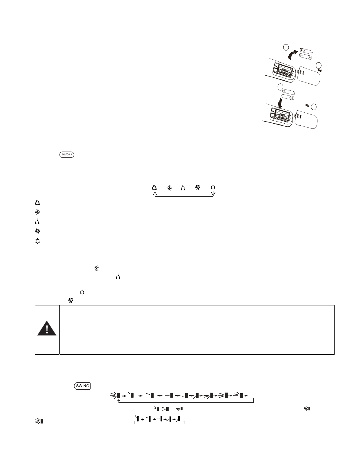
Use two new alkaline type batteries with AAA 1,5V.
(1) Slide down the cover of the battery compartment.
Remove the used batteries and insert new ones correctly.
(2) Reattach the cover by sliding it back into its position.
Notes
♦ Do not use old batteries or different type batteries. Such a use may cause remote control
wrong functioning.
♦ If you do not use the remote control more than two weeks, remove the batteries. Damages
may be caused by possible leakages.
♦ Replace batteries when no "beep" is received from the indoor unit or if the transmission
indicator on the remote controller fails to light.
1
2
3
4
4.4. How to use the remote control to operate the unit
● SWITCHING THE UNIT ON AND OFF
Press the
key to switch the unit on or off.
● SETTING THE OPERATING MODE
By pressing the Mode key several times it is possible to change the unit operating mode. The selected operating mode
symbol appears on the display.
→ → → →
: automatic mode
: cooling mode
: dehumidification mode
: fan only mode
: heating mode
When the automatic programme AUTO is selected, the unit may operate in COOLING or HEATING mode depending on the
temperature difference in place between the ambient temperature and the temperature selected on the remote control.
When the cooling mode
is selected, the unit operates with a free temperature setting, lowering the ambient temperature.
When the dehumidification mode
is selected, the unit operates with a free temperature setting, progressively lowering the
ambient temperature and humidity. When the dehumidification mode is in operation, the FAN button cannot be used. When
the heating mode
is selected, the unit operates with a free temperature setting, raising the ambient temperature. When
the fan mode
is selected, the unit operates without temperature settings, simply blowing air through the environment.
IMPORTANT!
♦ The unit fan stops when the set temperature is reached and is then automatically reactivated at minimum
speed to prevent air stratification phenomena in the vicinity of the appliance.
♦ When the COOLING,
DEHUMIDIFICATION mode is selected, the fan may not start up straight away because the
ANTI-HEATING mode is present. When the HEATING mode is selected, the fan may not start up straight away
because the ANTI-COOLING mode is present.
● SETTING THE LOUVER
In order to obtain optimal air distribution, adjust the motorised louver, making sure that the air flow is not directly pointed at
anyone. For the motorised louver, proceed as follows:
By pressing the
key it is possible to select swing angle, which circularly changes as below
OF
F
Note: This remoter is universal. If any command , or is sent out, the unit will carry out the command as .
indicates the guide louver swings as:
Page 25
24
● SETTING THE FAN
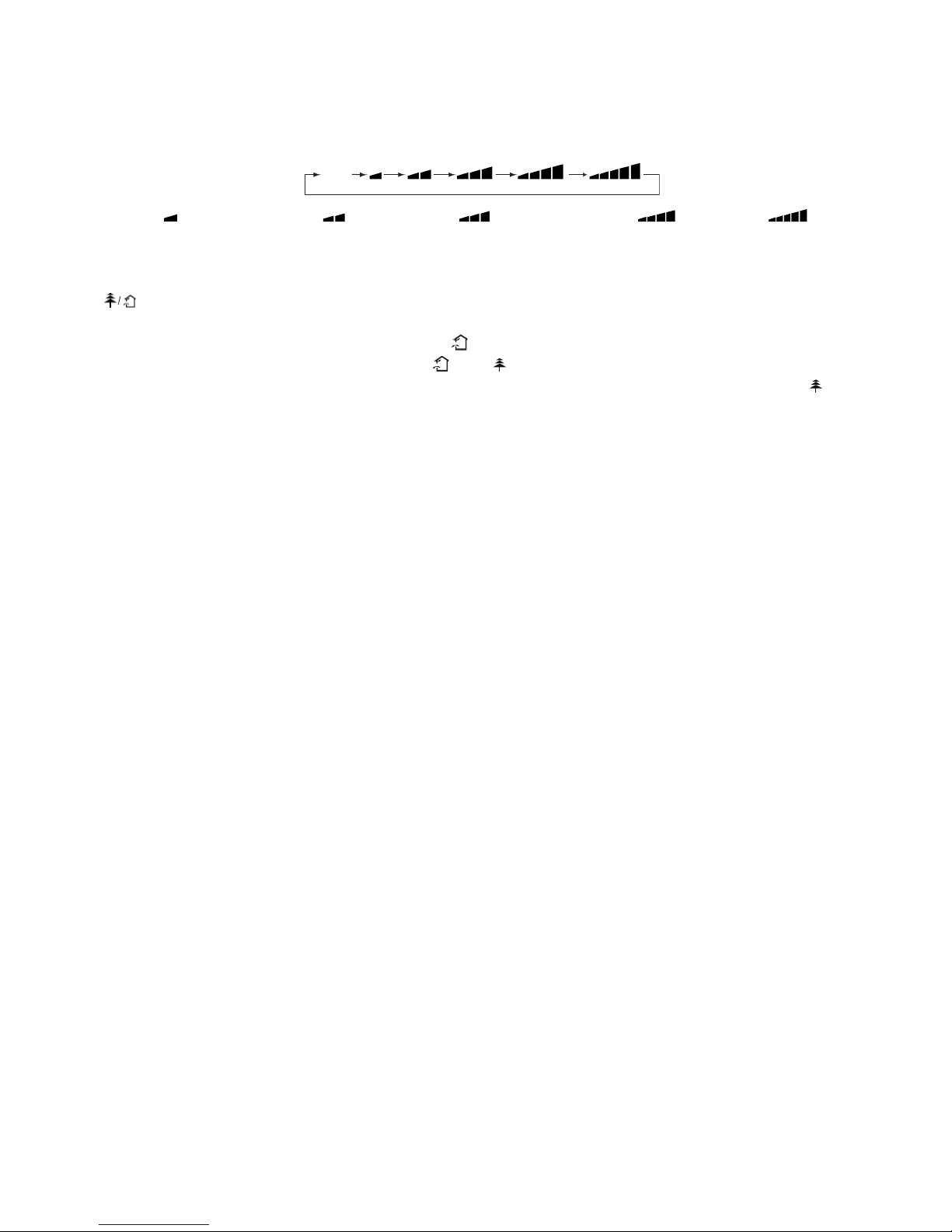
By pressing the FAN key several times it is possible to adjust the fan speed between the three available speeds, or to
activate the AUTO mode. The operating mode appears on the display:
Auto
Auto, Low ( ), Low-Medium speed ( ), Medium speed ( ), Medium-High speed ( ), High speed ( ).
● I FEEL FUNCTION SETTING
Press this button to turn on I FEEL function. The unit automatically adjusts temperature according to the sensed
temperature. Press this button again to cancel I FEEL function.
●
FUNCTION
Press this button to achieve the on and off of healthy and scavenging functions in operation status. Press this button for the
first time to start scavenging function; LCD displays “
”. Press the button for the second time to start healthy and
scavenging functions simultaneously; LCD displays “
” and “ ”. Press this button for the third time to quit healthy and
scavenging functions simultaneously. Press the button for the fourth time to start healthy function; LCD display “
”. Press
this button again to repeat the operation above.
● SLEEP MODE SETTING
SLEEP mode can be set in COOLING or HEATING operation mode. This function gives you a more comfortable
environment for sleep.
In SLEEP mode,
♦ Fan speed is automatically set at low speed.
♦ Press the "SLEEP" button to set the unit to the sleep mode. The SLEEP indicator will light up on the display. The
temperature increases/decrease in cooling/heating mode operation by 1°C at set intervals. After reaching 2°C the unit
maintains this temperature through to the eighth hour (8 hours) of operation in the "SLEEP" mode and then switches off
automatically.
● TEMP FUNCTION
Press TEMP key to show the set point temperature, indoor ambient temperature and outdoor ambient temperature on the
unit’s display.
Note: Outdoor ambient temperature is only displayed for some models.
● CLOCK SETTING
To adjust the real time press CLOCK button, then use ''+'' and ''-'' buttons to get the correct time.
♦ Press the key ''+'' / ''-'' once to increase/decrease the time setting by 1 minute.
♦ Press the key ''+'' / ''-'' for 2 seconds to increase/decrease the time setting by 10 minutes.
♦ Press CLOCK button again the real time is set.
● TIMER MODE SETTING
Push the buttons TIMER ON/OFF to set the timer programming as wished in order to switch on and off the air conditioner at
the desired time.
- How to set TIMER ON
TIMER ON button can be used to set the timer programming as wished in order to switch on the appliance at your desired
time.
1) Press TIMER ON button, "ON" flashes on the LCD, then you can press the ''+'' or ''-'' buttons to select your desired time
for appliance on.
♦ Press the ''+'' / ''-'' button once to increase or decrease the time setting by 1 minute.
♦ Press the key ''+'' / ''-'' for 2 seconds to increase/decrease the time setting by 10 minutes.
Note: If you don't set the time in 10 seconds after you press TIMER ON button, the remote controller will exit the TIMER ON
mode automatically.
2) When your desired time displayed on LCD, press the TIMER ON button and confirm it, a beep can be heard and then the
TIMER indicator "ON" the indoor unit stops flashing.
3) After the set timer displayed, the clock will be displayed on the LCD of the remote controller instead of set timer.
Page 26

25
- How to cancel TIMER ON
Press the TIMER ON button again, a "beep" can be heard and the indicator disappears, the TIMER ON mode has been
cancelled.
Note: It is similar to set TIMER OFF; you can make the appliance switch off automatically at your desired time.
● TURBO MODE SETTING:
♦ TURBO mode is used to start or stop fast cooling and heating at high fan speed.
♦ In Turbo mode, you can set airflow direction or timer. If you want to exit from TURBO mode, press any - TURBO, MODE,
FAN or ON/OFF button, the display will return to the original mode.
● LIGHT FUNCTION
Press LIGHT button to turn on the display's light and press this button again to turn off the display's light. If the light is turned
on, is displayed. If the light is turned off,
disappears.
● X-FAN FUNCTION
Pressing X-FAN button in COOL or DRY mode, the icon
is displayed and the indoor fan will continue operation for 10
minutes in order to dry the indoor unit even though you have turned off the unit.
After energization, X-FAN OFF is defaulted. X-FAN is not available in AUTO, FAN or HEAT mode.
● LOCK FUNCTION
Press the ''+'' and ''-'' keys at the same time to block the last setting operation by the remote controller.
All the keys disabled, including the ON/OFF key. Press the ''+'' and ''-'' keys again to enable the buttons functions.
● °C / °F FUNCTION
Press the ''MODE'' and ''-'' buttons at the same time with the unit off to choose the display of temperature in °C and °F.
● ENERGY-SAVING FUNCTION
Press “TEMP” and “CLOCK” simultaneously in COOL mode to start energy-saving function.
Nixie tube on the remote controller displays “SE”. Repeat the operation to quit the function.
● 8°C HEATING FUNCTION
Press “TEMP” and “CLOCK” simultaneously in HEAT mode to start 8°C Heating Function Nixie tube on the remote
controller displays
and a selected temperature of “8°C”.
(46 if Fahrenheit is adopted). Repeat the operation to quit the function.
Page 27
26
5. MAINTENANCE
No
Household
Drai n
Clea ner
WARNING
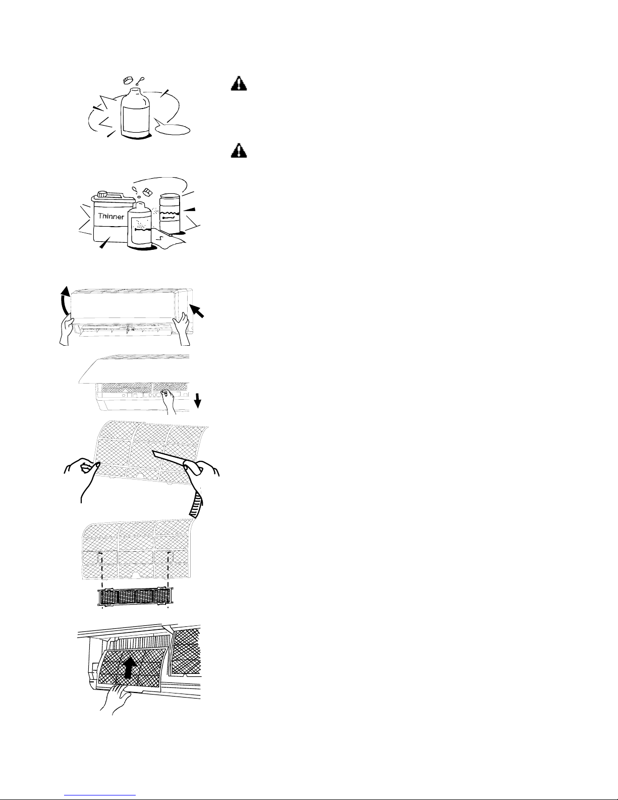
It is necessary to stop the air conditioner and disconnect the power supply before
cleaning.
Cleaning the indoor unit and remote controller
CAUTIONS
- Use a dry cloth to wipe the indoor unit and remote controller.
- A cloth dampened with cold water may be used on the indoor unit if it is very
dirty.
- The front panel of the indoor unit can be removed and cleaned with water. Then
wipe it with a dry cloth.
- Do not use a chemically treated cloth or duster to clean the unit.
- Do not use benzene, thinner, polishing powder, or similar solvents for cleaning.
These may cause the plastic surface to crack or deform.
Cleaning the air filter
A clogged air filter reduces the cooling efficiency of this unit. Please clean the filter
once every 2 weeks.
1. Lift the indoor unit panel up to an angle until it stops with a clicking sound.
2. Take hold of the handle of the air filter and lift it up slightly to take it out from the
filter holder, and then pull it downwards.
3. Remove the AIR FILTER from the indoor unit.
- Clean the AIR FILTER once two weeks.
- Clean the AIR FILTER with a vacuum cleaner or water, and then dry it up cool
place.
4. Remove the healthy filter from its support frame as shown in the Figure on the
left (Not applicable to the units without electrostatic filter).
Do not touch this Electrostatic Filter within 10 minutes after opening the inlet grille;
it may cause an electric shock.
- Clean the electrostatic filter with mild detergent or water and dry in the sunlight
for two hours.
- Before re-install the Electrostatic Filter, check whether the corona line or support
frame is damaged or not.
5. Install the air freshening filter back into position.
6. Insert the upper portion of air filter back into the unit taking care that the left and
right edges line up correctly and place filter into position.
Maintenance
If you plan to idle the unit for a long time, perform the following:
(1) Operate the fan for about half a day to dry the inside of the unit.
(2) Stop the air conditioner and disconnect power. Remove the batteries from the
remote controller.
(3) The outdoor unit requires periodic maintenance and cleaning. Do not attempt
to do this yourself. Contact your dealer or servicer.
Page 28

27
Checks before operation
• Check that the wiring is not broken off or disconnected.
• Check that the air filter is installed.
• Check if the air outlet or inlet is blocked after the air conditioner has not been used for a long time.
CAUTIONS
• Do not touch the metal parts of the unit when removing the filter. Injuries can occur when handling sharp metal edges.
• Do not use water to clean inside the air conditioner. Exposure to water can destroy the insulation, leading to possible
electric shock.
• When cleaning the unit, first make sure that the power and circuit breaker are turned off.
6. OPERATIONS AND PERFORMANCES
The following events may occur during normal operation.
1. Protection of the air conditioner.
Compressor protection
- The compressor can't restart for 3 minutes after it stops.
Anti-cold air (Cooling and heating models only)
- The unit is designed not to blow cold air on HEAT mode, when the indoor heat exchanger is in one of the following three
situations and the set temperature has not been reached.
A) When heating has just starting.
B) Defrosting.
C) Low temperature heating.
- The indoor or outdoor fan stop running when defrosting (Cooling and heating models only). Defrosting (Cooling and
heating models only)
- Frost may be generated on the outdoor unit during heat cycle when outdoor temperature is low and humidity is high
resulting in lower heating efficiency of the air conditioner.
- During this condition air conditioner will stop heating operation and start defrosting automatically.
- The time to defrost may vary from 4 to 10 minutes according to the outdoor temperature and the amount of frost build-up
on the outdoor unit.
2. A white mist coming out from the indoor unit
- A white mist may generate due to a large temperature difference between air inlet and air outlet on COOL mode in an
indoor environment that has a high relative humidity.
- A white mist may generate due to moisture generated from defrosting process when the air conditioner restarts in HEAT
mode operation after defrosting.
3. Low noise of the air conditioner
- You may hear a low hissing sound when the compressor is running or has just stopped running. This sound is the sound of
the refrigerant flowing or coming to a stop.
- You can also hear a low "squeak" sound when the compressor is running or has just stopped running. This is caused by
heat expansion and cold contraction of the plastic parts in the unit when the temperature is changing.
- A noise may be heard due to louver restoring to its original position when power is first turned on.
4. Dust is blown out from the indoor unit.
This is a normal condition when the air conditioner has not been used for a long time or during first use of the unit.
Page 29

28
5. A peculiar smell comes out from the indoor unit.
This is caused by the indoor unit giving off smells permeated from building material, from furniture, or smoke.
6. The air conditioner turns to FAN only mode from COOL or HEAT (For cooling and heating models only) mode.
When indoor temperature reaches the temperature setting on air conditioner, the compressor will stop automatically, and
the air conditioner turns to FAN only mode. The compressor will start again when the indoor temperature rises on COOL
mode or falls on HEAT mode (For cooling and heating models only) to the set point.
7. Dripping water may generate on the surface of the indoor unit when cooling in a high relatively humidity (relative
humidity higher than 80%).
Adjust the horizontal louver to the maximum air outlet position and select HIGH fan speed.
8. Heating mode (For cooling and heating models only)
The air conditioner draws in heat from the outdoor unit and releases it via the indoor unit during heating operation. When the
outdoor temperature falls, heat drawn in by the air conditioner decreases accordingly. At the same time, heat loading of the
air conditioner increases due to larger difference between indoor and outdoor temperature. If a comfortable temperature
can't be achieved by the air conditioner, we suggest you use a supplementary heating device.
9. Auto-restart function
Power failure during operation will stop the unit completely.
For the unit without Auto-restart feature, when the power restores, the OPERATION indicator on the indoor unit starts
flashing. To restart the operation, push the ON/OFF button on the remote controller. For the unit with Auto-restart feature,
when the power restores, the unit restarts automatically with all the previous settings preserved by the memory function.
10. Lightning or a car wireless telephone operating nearby may cause the unit to malfunction.
Disconnect the unit with power and then re-connect the unit with power again. Push the ON/OFF button on the remote
controller to restart operation.
Page 30
29
ENGLISH
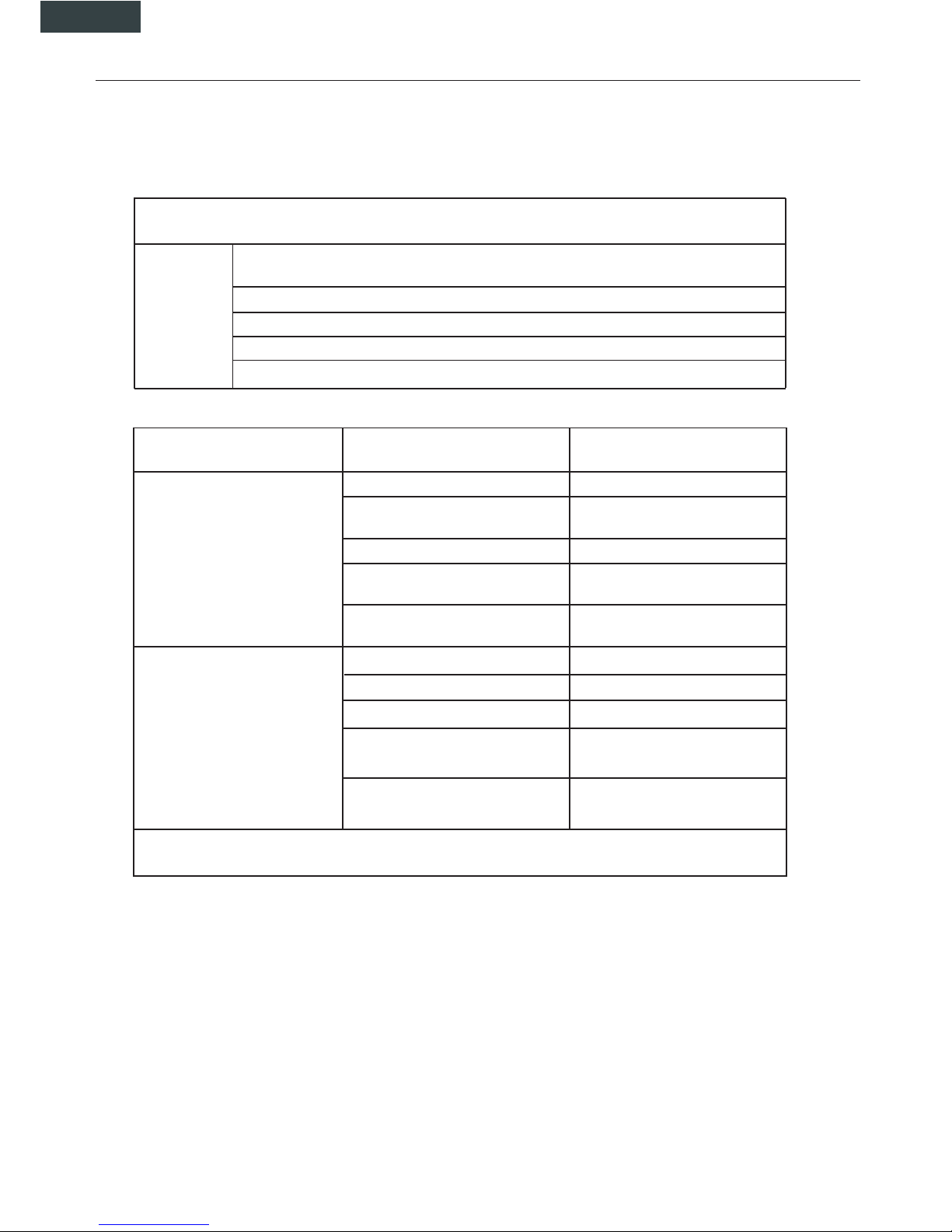
7. TROUBLES AND CAUSES
TROUBLES AND CAUSES
Stop the air conditioner immediately if one of the following faults occur. Disconnect the power and contact
the nearest custmer service center.
OPERATION indicator or other indicators flash rapidly (5 times every second) and this flash
cannot be fixed by disconnecting the power, and then connect it again
Fuse blows frequently or circuit breaker trips frequently
Other objects or water penetrate the air conditioner
The remote controller won’t work or works abnormally
Other abnormal situations
Trouble
Malfunctions
Cause
What should be done?
Unit does not start
Powe cut Wait for power to be restored
Unit may have become unplugged.
Check that plug is securely in wall
receptable
Fuse may have blown.
Replace the fuse
Battery in remote controller may
have been exhausted.
Replace the battery
The time you have set with timer is
incorrect.
Wait or cancel timer setting
Unit not cooling or heating (Cooling/heating models only) room
very well while air flowing out from
theair conditioner
Inappropriate temperature setting
set temperature correctly
Air filter is blocked
Clean the air filter
Air inlet or outlet of indoor or
outdoor unit has been blocked
Doors or Windows are open Close the doors or windows
Clear obstructions away first, then
restart the unit
Compressor 3 minutes protection
has been achieved
Wait
If the trouble has not been corrected, please contact a local dealer or the nearest custmer service center. Be
sure to inform them of the detailed malfunctions and unit model.
Notes:
- Do not attempt to repair the unit yourself.
- Always consult an authorised service provider.
Page 31
30
8. INSTALLATION
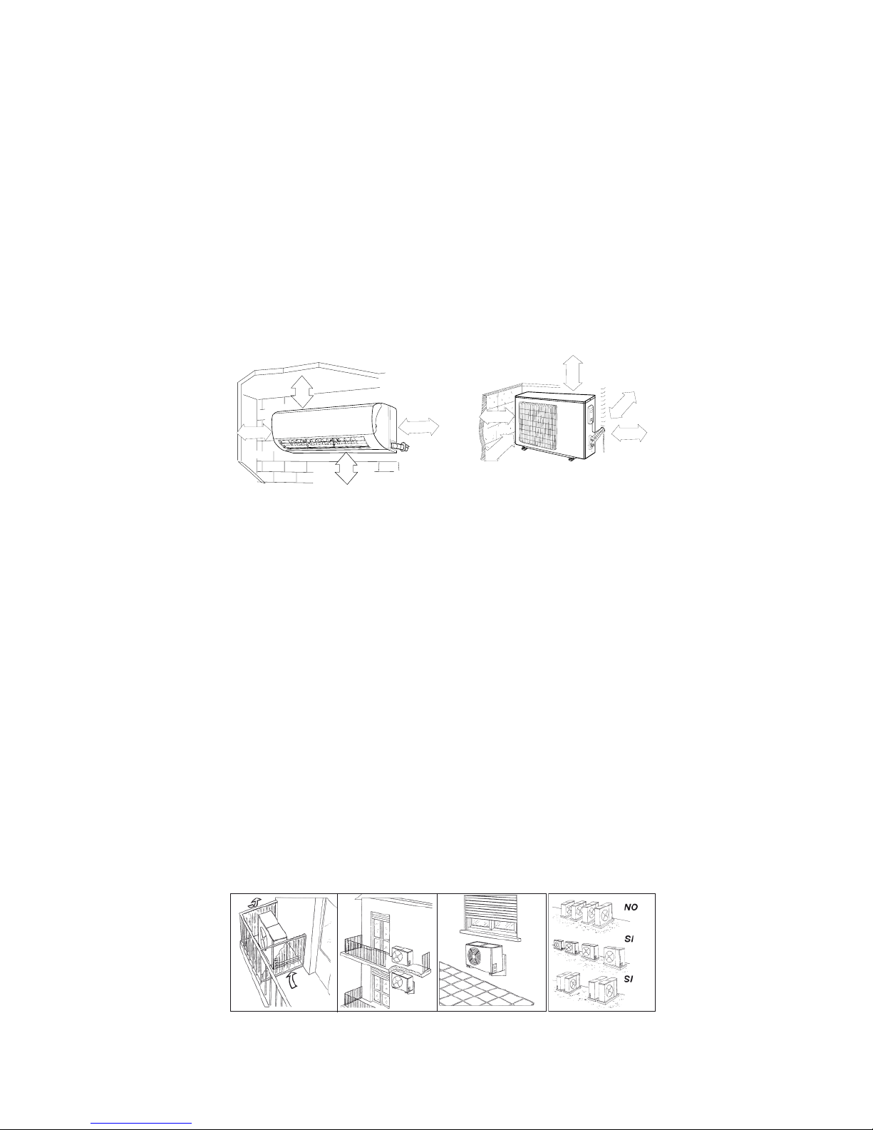
Indoor unit
• Do not expose the indoor unit to heat or steam.
• Select a place where there are no obstacles in front or around the unit.
• Make sure that condensation drainage can be conveniently routed away.
• Do not install near a doorway.
• Ensure that the space on the left and right of the unit is more than 12cm.
• Use a stud finder to locate studs to prevent unnecessary damage to the wall.
• A minimum pipe run of 3 metres is required to minimise vibration & excessive noise.
• The indoor unit should be installed on the wall at a height of 2.3 metres or more from the floor.
• The indoor unit should be installed allowing a minimum clearance of 15cm from the ceiling.
• Any variations in pipe length will/may require adjustment to refrigerant charge.
2
≤
2
5
0
c
m
0
2
0
≤
60 cm
≤
5
0
c
m
≤
1
5
c
m
≤ 15 cm
≤ 15 cm
≤
1
5
c
m
≤
1
5
c
m
≤
60 cm
Outdoor unit
If an awning is built over the outdoor unit to prevent direct sunlight or rain exposure, make sure that heat radiation from the
condenser is not restricted.
• Ensure that the clearance around the back of the unit is more than 30cm and left side is more than 30cm. The front of the
unit should have more than 200cm of clearance and the connection side (right side) should have more than 60cm of
clearance. Do not place animals and plants in the path of the air inlet or outlet.
• Take the air conditioner weight into account and select a place where noise and vibration will not be an issue.
• Select a place so that the warm air and noise from the air conditioner do not disturb neighbours.
• Install the outdoor unit on a rigid base to prevent increasing noise level and vibration.
• Determine the air outlet direction where the discharged air is not blocked.
• In the case that the installation place is exposed to strong wind such as a seaside, make sure the fan operating properly by
putting the unit lengthwise along the wall or using a dust or shield plates.
• Specially in windy area, install the unit to prevent the admission of wind.
• If need suspending installation, the installation bracket should accord with technique requirement in the installation bracket
diagram. The installation wall should be solid brick, concrete or the same intensity construction, or actions to reinforce,
damping supporting should be taken. The connection between bracket and wall, bracket and the air conditioner should be
firm, stable and reliable.
• Be sure there is no obstacles which block radiating air.
Page 32
31
ENGLISH
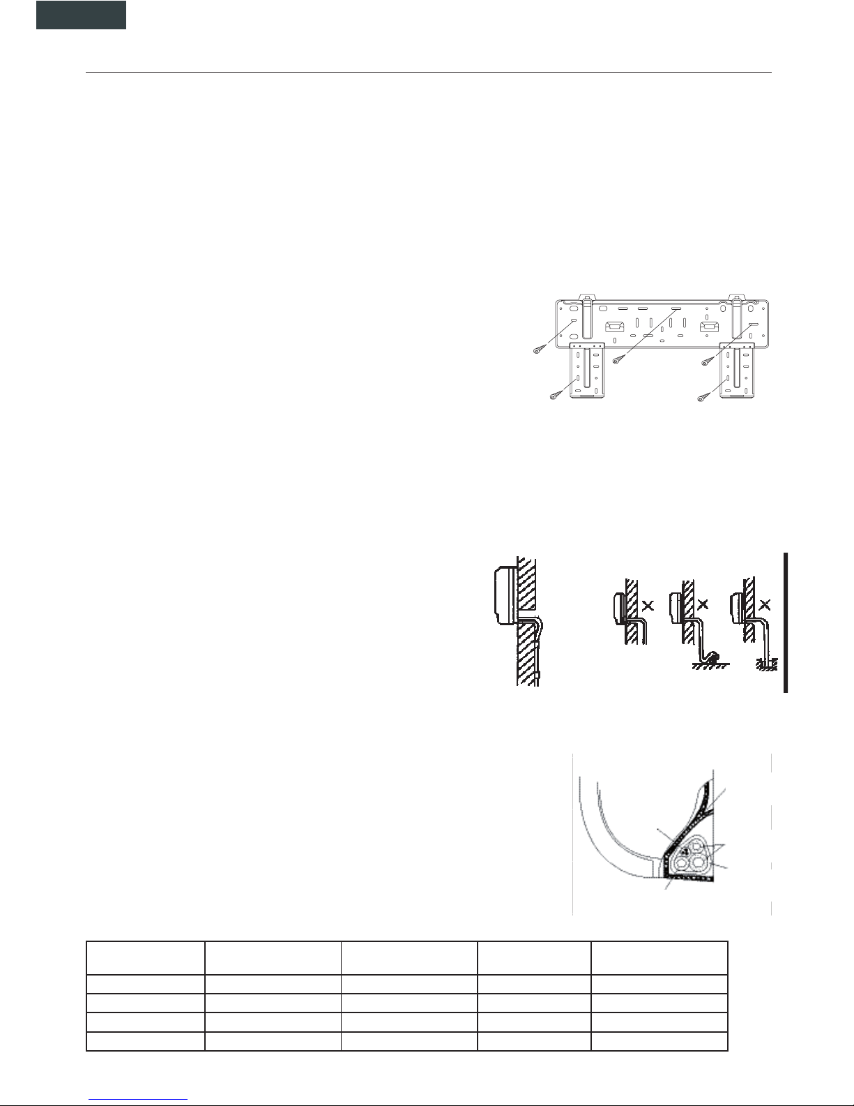
8. INSTALLATION
Fit the installation Plate
1. Fit the installation plate horizontally on structural parts of the wall with spaces around the installation plate.
2. If the wall is made of brick, concrete or the like, drill eight (8) 5mm diameter holes in the wall. Insert Clip anchor for appropriate
mounting screws.
3. Fit the installation plate on the wall with eight (8) type "A" screws.Fit the Installation Plate and drill holes in the wall according
to the wall structure and corresponding mounting points on the installation plate. (Dimensions are in "mm" unless otherwise sta
ted).
Drill a hole in the wall
1. Determine hole positions according to the diagram detailed in Fig.5. Drill one (1) hole (65mm) slanting slightly to outdoor side
2. Always use wall hole conduit when drilling metal metal plate or the like.
Connective Pipe and Drainage Installation
1. Run the drain hose sloping downward. Do not install the drain hose as illustrated below.
2. When connecting extension drain hose, insulate the connecting part of extension
drain hose with a shield pipe, do not let the drain hose slack.
Connective pipe
1. For the left-hand and right-hand piping, remove the pipe cover from the side panel.
Explain to clients that the pipe cover must be kept as it may be used when relocate the air conditioner to any other place.
2. For the rear-right-hand and rear-left-hand piping, install the piping as shown. Bend the connective pipe to be laid at 43mm hei
ght or less from the wall.
3. Fix the end of the connective pipe. (Refer to Tightening Connection in REFRIGERANT PIPING CONNECTION).
Indoor unit installation
1. Pass the piping through the hole in the wall.
2. Put the upper claw at the back of the indoor unit on the upper hook of the installation plate, move the indoor unit from side to
side to see that it is securely hooked.
3. Piping can easily be made by lifting the indoor unit with a cushioning
material between the indoor unit and the wall. Get it out after piping.
4. Push the lower part of the indoor unit up on the wall. Then move the
indoor unit from side to side, up and down to check if it is hooked secu
rely.
Settlement of outdoor unit
Anchor the outdoor unit with a bolt and nut 10 or 8 tightly and horizontally
on a concrete or rigid mount.
Drain joint installation
Fit the seal into the drain elbow, then insert the drain joint into the base pan
hole of outdoor unit, rotate 90 to securely assemble them. Connecting the
drain joint with an extension drain hose (Locally purchased), in case of the water draining off the outdoor unit during the heating
mode.
Piping and wrapping
Bundle the tubing, connecting cable,anddrain hose with tape securely.
• Because the condensed water from rear of the indoor unit is gathered in ponding box and is
piped out of room. Do not put anything else in the box.
CAUTION
• Connect the indoor unit first, then the outdoor unit.
• Do not allow the piping to let out from the back of the indoor unit.
• Be careful not to let the drain hose slack.
• Heat insulated both of the auxiliary piping.
• Be sure that the drain hose is located at the lowest side of the bundle. Locating at the
upper side can cause drain pan to over flow inside the unit.
• Never intercross nor intertwist the power wire with any other wiring.
• Run the drain hose sloped downward to drain out the condensed water smoothly.
Outdoor unit Model Connective pipe length
max (m)
Connective pipe
length (m)
Difference in level
H (m)
Additional amount of refri-
gerant to be charge (g/m)
1 x 2 10 20 5 20
1 x 3 30 70 10 20
1 x 4 40 70 10 20
1 x 5 50 80 15 22
Indoor unit
Drain hose
Wrapping
belt
Connective
pipe
Ponding box
Connective
cable
Page 33
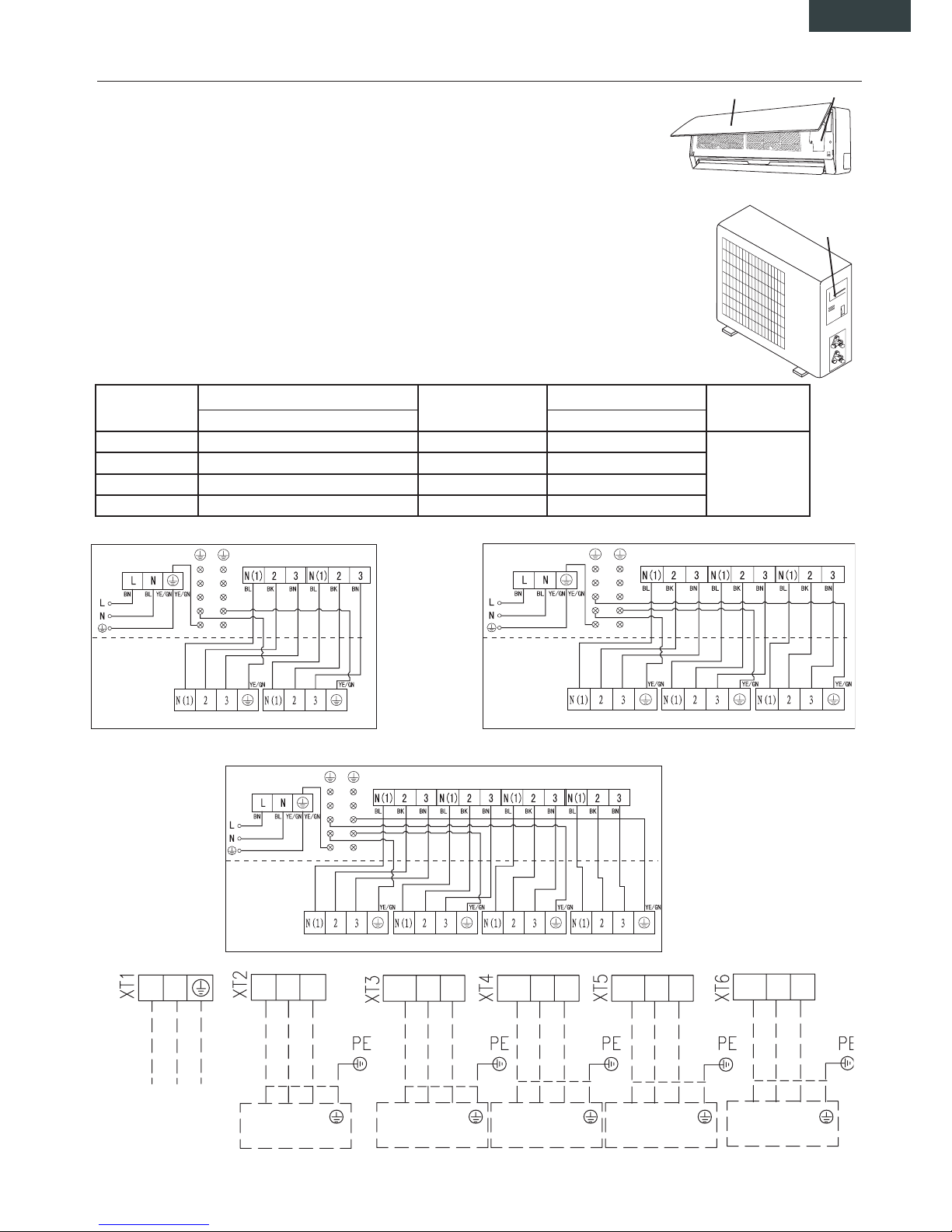
32
ENGLISH
Wiring connections
Connect the cable to the indoor unit
1. Indoor/Outdoor connection cable should be H07RN-F type.
2. Lift the indoor unit panel up and remove the screw, then remove the window cover.
3. Connect cables according to their marks to terminals.
4. Wrap those cables not connected with terminals with insulation tapes, so that they will not touch
any electrical components.
Connect the cable to the outdoor unit
1. Remove the electric parts cover from the outdoor unit.
2. Connect the connective cables to the terminals as identified with their respective matched num
bers on the terminal block of indoor and outdoor units.
3. To prevent the ingress of water, from a loop of the connective cable as illustrated in the installation
diagram of indoor and outdoor units.
4. Insulate unused cords (conductors) with PVC-tape. Process them so they do not touch any electri
cal or metal parts.
Wires specifications
8. INSTALLATION
INDOOR UNIT
OUTDOOR UNIT
Front panel Terminal
Acces door
terminal
INDOOR A XT1
INDOOR A XT1
INDOOR A XT1
INDOOR UNITS
A B C D
INDOOR B XT1 INDOOR C XT1 INDOOR D XT1
INDOOR UNITS A B C
OUTDOOR UNIT
OUTDOOR UNIT
OUTDOOR UNIT
INDOOR B XT1 INDOOR C XT1
INDOOR UNITS A B
INDOOR B XT1
1 x 2 MULTI DC INVERTER 1 x 3 MULTI DC INVERTER
1 x 4 MULTI DC INVERTER
1 x 5 MULTI DC INVERTER
L N
2 3
N(1)
2 3
N(1)
2 3
N(1)
2 3
N(1)
2 3
N(1)
2 3
N(1)
2 3 2 3 2 3 2 3
N(1)
N(1)
N(1) N(1)
INDOOR UNIT A INDOOR UNIT B INDOOR UNIT C INDOOR UNIT D
INDOOR UNIT E
POWER / ALIMENTAZIONE
TO OUTDOOR UNIT
Indoor unit (W)
Indoor - outdoor connecting cable
Outdoor unit
Power connecting cable Alimentazione
principale
Section Section
2600 W 4 x 1,0 mm² 1 x 2 DC inverter 3 x 2,5 mm²
To outdoor unit
5300 W 4 x 1,0 mm² 1 x 3 DC inverter 3 x 4,0 mm²
5300 W 4 x 1,0 mm² 1 x 4 DC inverter 3 x 4,0 mm²
1 x 5 DC inverter 3 x 6,0 mm²
Page 34
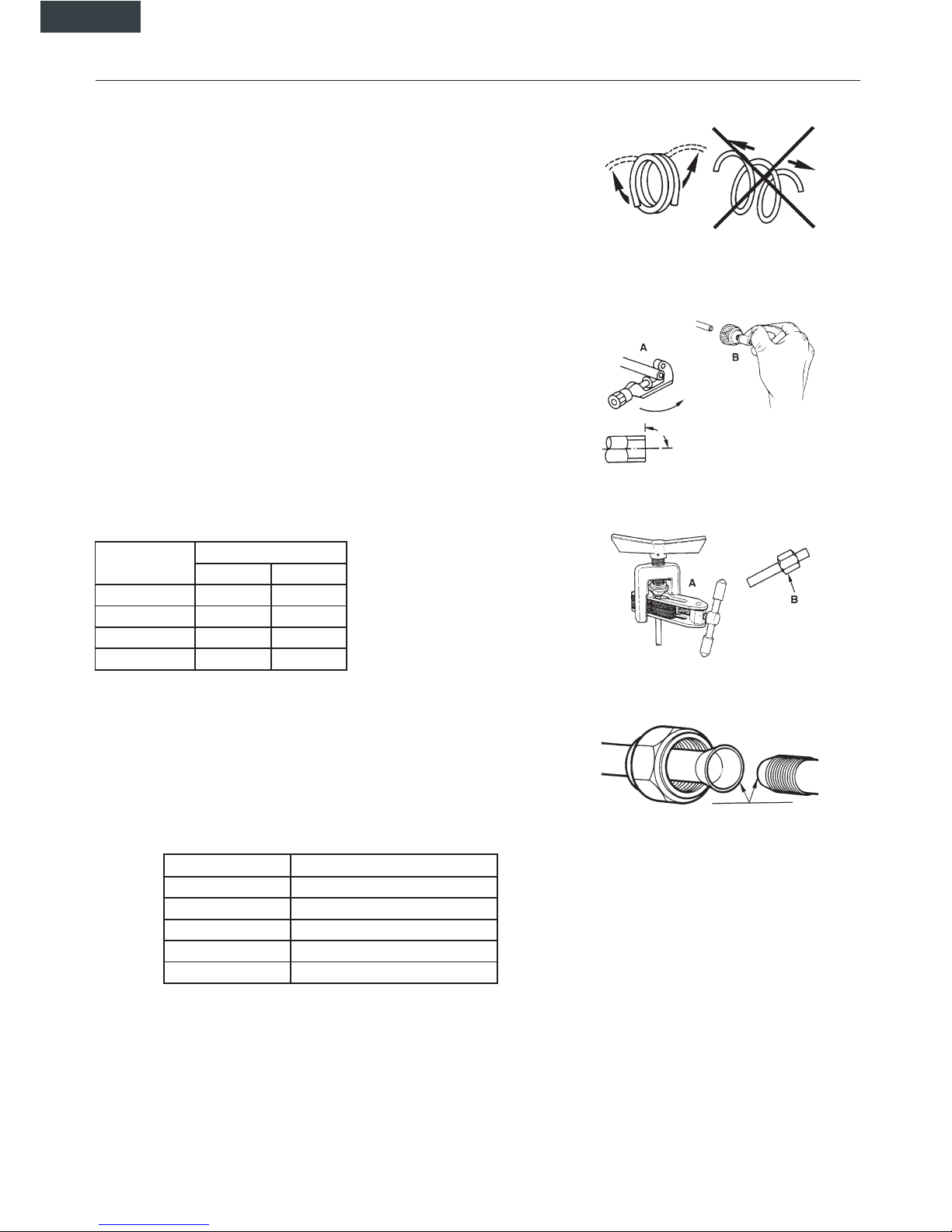
33
ENGLISH
8. INSTALLATION
Refrigerant piping connection
1. Flaring work
Main cause for refrigerant leakage is due to defect in the flaring work. Carry out correct flaring work using the following procedure:
A: Cut the pipes and the cable.
1. Use the piping kit accessory or pipes purchased locally.
2. Measure the distance between the indoor and the outdoor unit.
3. Cut the pipes a little longer than the measured distance.
4. Cut the cable 1.5m longer than the pipe length.
B: Burr removal
1. Completely remove all burrs from the cut cross section of pipe/tube
2. Put the end of the copper tube/pipe in a downward direction as you remove
burrs in order to avoid dropping burrs into the tubing.
C: Putting nut on
Remove flare nuts attached to indoor and outdoor unit, then put them on pipe/tube
having completed burr removal. (Not possible to put them on after flaring work).
D: Flaring work
Firmly hold copper pipe in a die in the dimension shown in the table below.
Diam. E (mm) A(mm)
Max. Min
Φ6,35 1,3 0,7
Φ9,35 1,6 1
Φ12 1,8 1
Φ16 2 1
Tightening Connection
• Align the center of the pipes.
• Sufficiently tighten the flare nut with fingers, and then tighten it with a spanner
and torque wrench as shown.
CAUTION
• Excessive torque can break nut depending on installation conditions.
Hex nut diam. Tightening torque (N.m)
Φ 6 15 ~ 20
Φ 9,52 31 ~ 35
Φ 12 50 ~ 55
Φ 16 60 ~ 65
Φ 19 70 ~ 75
Page 35
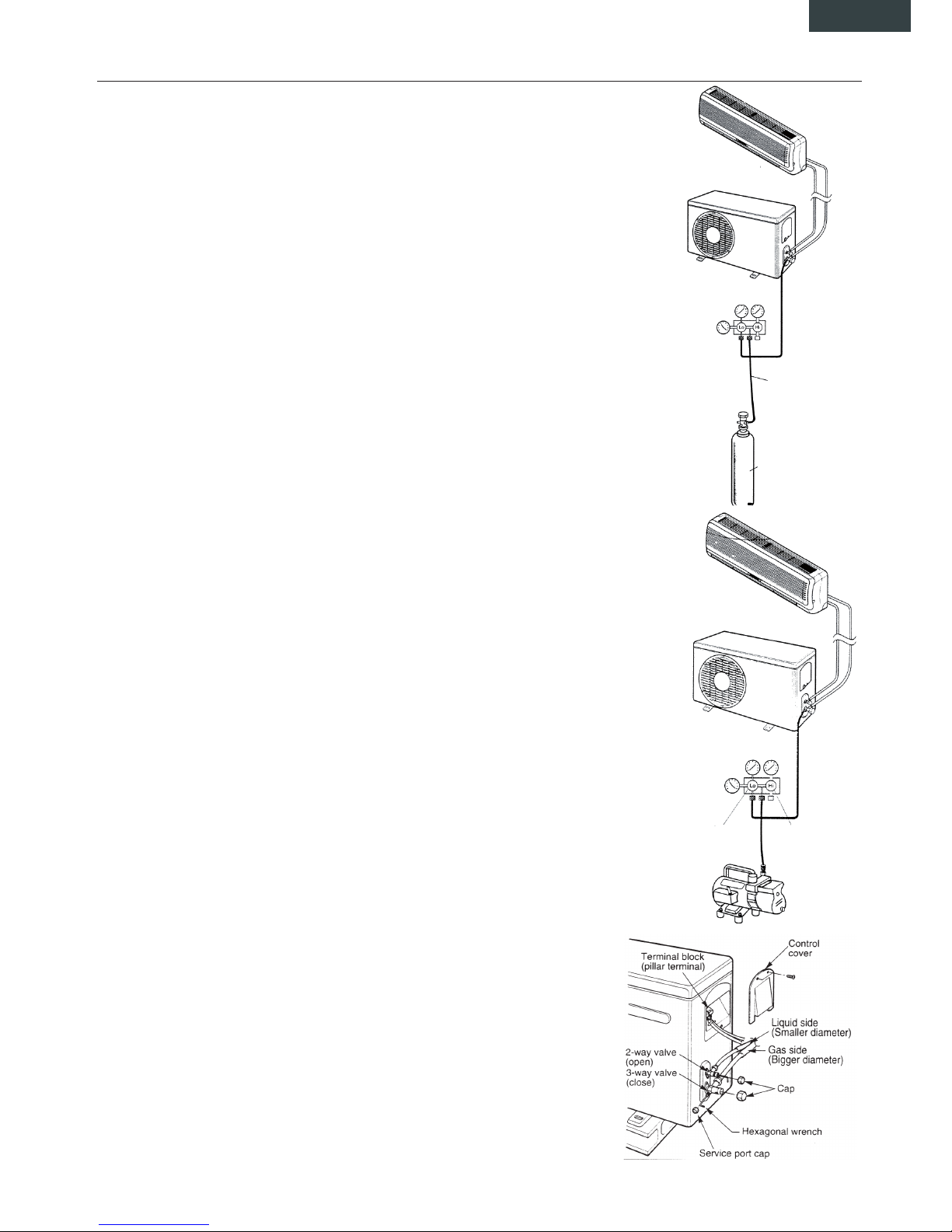
34
ENGLISH
8. INSTALLATION
Indoor unit
Outdoor unit
Manifold gauge
Pressure
gauge
Charge hose
Nitrogen gas cylinder
(in vertical position)
Air purging
Air and moisture in the refrigerant system have undesirable effects as indicated
below:
• Pressure in the system rises.
• Operating current rises.
• Cooling or heating efficiency drops.
• Moisture in the refrigerant circuit may freeze and block capillary tubing.
• Water may lead to corrosion of parts in the refrigeration system.
Therefore, the indoor unit and tubing between the indoor and outdoor unit must be
leak tested and evacuated to remove any noncondensables and moisture from the
system.
Air purging with vacuum pump
• Preparation
Check that each tube (both liquid and gas side tubes) between the indoor and
outdoor units have been properly connected and all wiring for the test run has
been completed. Remove the service valve caps from both the gas and the liquid
side on the outdoor unit.
Note that both the liquid and the gas side service valves on the outdoor unit are
kept closed at this stage.
• Pipe length and refrigerant amount:
• When relocate the unit to another place, perform evacuation using vacuum
pump.
Make sure the refrigerant added into the air conditioner is liquid form in any case.
Caution in handling the packed valve
• Open the valve stem until it hits against the stopper. Do not try to open it further.
• Securely tighten the valve stem cap with aspanner or the like.
• Valve stem cap tightening torque (See Tightening torque table in previous page).
When Using the Vacuum Pump
(For method of using a manifold valve, refer to its operation manual.)
1. Completely tighten the flare nuts, A, B, C, D, connect the manifold valve charge
hose to a charge port of the low-pressure valve on the gas pipe side.
2. Connect the charge hose connection to the vacuum pump.
3. Fully open the handle Lo of the manifold valve.
4. Operate the vacuum pump to evacuate. After starting evacuation, slightly loose
the flare nut of the Lo valve on the gas pipe side and check that the air is ente
ring (Operation noise of the vacuum pump changes and a compound meter indi
cates 0 instead of minus)
5. After the evacuation is complete, fully close the handle Lo of the manifold valve
and stop the operation of the vacuum pump.
Make evacuation for 15 minutes or more and check that the compound meter
indicates -76cmHg(-1x10⁵Pa).
6. Turn the stem of the packed valve B about 45°counterclockwise for 6-7 seconds
after the gas coming out, then tighten the flare nut again. Make sure the pressu
re display in the pressure indicator is a little higher than the atmosphere
pressure.
7. Remove the charge hose from the Low pressure
charge hose.
8. Fully open the packed valve stems B and A.
9. Securely tighten the cap of the packed valve.
Indoor unit
Outdoor unit
Pressure
gauge
Manifold gauge
Open
Close
Vacuum pump
Page 36
35
9. TEST OPERATION
• The test operation must be carried out after the entire installation has been completed.
• Please confirm the following points before the test operation:
• The indoor unit and outdoor unit are installed properly.
• Tubing and wiring are correctly completed.
• The refrigerant pipe system is leakage-checked.
• The drainage is unimpeded.
• The heating insulation works well.
• The ground wiring is connected correctly.
• The length of the tubing and the added stow capacity of the refrigerant have been recorded.
• The power voltage fits the rated voltage of the air conditioner.
• There is no obstacle at the outlet and inlet of the outdoor and indoor units.
• The gas-side and liquid-side stop valves are both opened.
• The air conditioner is pre-heated by turning on the power.
TEST OPERATION
■ Set the air conditioner under the mode of "COOLING" with the remote controller, and check the following points. If there is
any malfunction, please resolve it according to the chapter "TROUBLESHOOTING" of this Manual".
1) The indoor unit
a) Whether the switch on the remote controller works well.
b) Whether the buttons on the remote controller works well.
c) Whether the air flow louver moves normally.
d) Whether the room temperature is adjusted well.
e) Whether the indicator lights normally.
f) Whether the temporary buttons works well.
g) Whether the drainage is normal.
h) Whether there is vibration or abnormal noise during operation.
i) Whether the air conditioner heats well.
2) The outdoor unit
a) Whether there is vibration or abnormal noise during operation.
b) Whether any of the refrigerant is leaked.
CAUTION
A protection feature prevents the air conditioner from being activated for approximately 3 minutes when it
is restarted immediately after shut off.
Page 37
Page 38
Page 39
Page 40
 Loading...