

Tekno Point iCFV-xxC/H Installation Manual

iCFV-xxC/H
INSTALLATION
MANUAL IDRA INVERTER
Water cooled
air conditioners
IDRA INVERTER

CONTENTS
GENERAL INFORMATION
SYMBOLS
3
PERMITTED USE
3
RECOMMEDATIONS
4
UNIT DESCRIPTION
CONSTRUCTIVE DESCRIPTION
6
BEFORE PROCEEDING WITH INSTALLATION
6
INSTALLA TION iCFV 11
MINIMUM DISTANCES
15
THICKNESS OF THE COPPER PIPES
19
CONNECTIONS OF THE EXTERNAL UNIT
20
ELECTRICAL CONNECTIONS 22
FINAL STAGES 23
E LECTRICAL WI RI NGS 25
MAINTENANCE 33
2
1 - GENERAL INFORMATION
1.1 SYMBOLS
In this publication and/or on this unit the following symbols have been used:
1.2 PERMITTED USE
These machines have been created to heat or cool the air. Use of the units for applications other than those
specifically authorised by the manufacturer is considered inappropriate and, therefore, not allowed. The company
declines all contractual and extra-contractual responsibility for damage caused to people, animals and objects
resulting from errors in installation, calibration and maintenance, improper use, or from the partial or superficial
reading of the information contained in this manual. In addition, keeping in mind the continued product
improvement, T.P.I . reserves the right to change the information found in this manual at any moment without
notice, and declines all responsibility for any inaccuracies in this manual, if due to errors in printing
or copying.
Carefully read this booklet; all operations must be carried out by expert and qualified personnel who are
familiar with the related laws in force in the different countries concerned.
The guarantee will be void in the event the above-mentioned instructions are not followed.
The documentation provided with the unit
must be given to the final client (user) so that it can be kept for
any future maintenance or assistance required.
Upon receipt of merchandise
from the carrier make sure that both the packaging and the unit are intact.
If
damage
or
missing
components
are
noted,
specify
this
on
the
delivery
note
upon
receipt
of
the
unit:
Check all the parts to make sure they have not been damaged during transport. Any damage noted must be
communicated to the carrier writing "accepted with reserve" on the accompanying note, specifying the type of
damage; in addition the company must be informed via fax or certified letter of the formal claim within 8 days
of the receipt of merchandise.
3
USER:
Information, paragraph, chapter of the
manual that concerns the user.
DANGER:
Calls attention to actions that, if
incorrectly carried out, may cause serious injury.
INSTALLER:
Information, paragraph or
chapter of manual that concerns the
installer.
PROHIBITED:
Calls attention to prohibited
TECHNICAL ASSISTANCE CENTRE:
Information, paragraph, chapter of the manual
that concerns the technical assistance centre.
VOLTAGE DANGER:
Calls attention to actions that,
if incorrectly carried out, may cause serious injury or
death to those directly exposed.
IMPORTANT:
Calls attention to technical
information or practical advice which makes
using the unit efficient and economical.
DANGER OF HIGH TEMPERATURE:
Calls
attention to actions that, if incorrectly carried out
may cause serious injury to people caused by the
high temperature of the components.
COMPULSORY: Calls attention to mandatory
actions in order to obtain correct machine
operation.

1 - GENERAL INFORMATION
1.3 RECOMMENDATIONS
Conserve the manual in a dry place, to avoid deterioration, for at least 10 years for future reference.
Completely
and carefully read all the information contained in this manual. Pay particular attention to the any rules
accompanied by the words
«
DANGER
», «
PROHIBITED
»
«
MANDATORY
» in that, if not followed, may cause
damage to the machine and/or people and objects. For potential problems not considered in this manual, promptly
consult T.P.I.'S service assistance centre. The manufacturer declines all responsibility for damage due to
improper machine use or the partial or superficial reading of the information contained in this manual.
The machine must be installed in such a way that makes maintenance and/or repair operations possible.
In any case, the guarantee does not cover, costs due to ladders, scaffolding or other systems of elevation which
may be necessary for carrying out repairs under guarantee.
The manufacturer does not issue drawings or specifications relative to connection systems.
Any deviation from the requirements contained in the following manual must be validated in writing by the
manufacturer's technical assistance department
1.4 FUNDAMENTAL SAFETY RULES
The use of products which utilise energy, electricity and water require following a few fundamental safety rules
including:
Use of the equipment
by children and unassisted disabled persons is prohibited.
Touching the unit while
not wearing shoes or if any part of the body wet or humid is prohibited.
All cleaning operations without having first disconnected the power supply are prohibited; to disconnect the
power, move the switch to the «off» position.
Modification of the safety devices
or adjustment without the authorisation and indications of the manufacturer
is prohibited.
Pulling, removing, or twisting the unit's electrical cables,
even if disconnected from the power supply is
prohibited.
Opening the access doors
to the unit's internal components if prohibited if the unit has not been turned
off via the main switch.
Climbing on, sitting on, and/or resting
any type of object on the unit is prohibited.
Spraying
or dumping water on the equipment is prohibited.
Dispersing or leaving the packaging materials
(cardboard, staples, plastic bags etc.) within the reach
of children is prohibited as they represent a source of potential danger.
Respect the distances of safety
between the machine and other equipment or structures in
order to ensure sufficient space when accessing the unit for carrying out maintenance and/or
technical assistance procedures as described in this manual (see 'technical spaces' chapter).
Powering the unit
: should be via electrical cables that have a section suitable to the power of the
unit and the voltage values must correspond to those indicated for the respective units; all of the
units must be earthed according to the laws in force in the various countries.
Hydraulic
connection must
be carried out as in the instructions in order to guarantee correct
operation of the unit. If, during the winter months, the unit is not running, the hydraulic circuit must
be emptied.
Handle the unit
with the utmost care; do not turn it upside down or place any items that
may cause damage on top of it.
Tampering with, removing, or damaging the unit's identification plates make installation, maintenance
and ordering spare parts difficult.
4

1 - GENERAL INFORMATION
1.5
RECEIPT OF PRODUCT AND HANDLING
The unit is supplied on a wooden pallet and protected by cardboard packaging.
The following are also provided with the unit:
- Instruction booklet
- Guarantee certificate
- EC declaration
- Anti-vibration feet, water filter, gas fitting for internal unit (in models where necessary)
- Ventilation unit documentation (in its own packaging)
- connection card (inside electrical panel)
The Use and Maintenance booklet is an integral part of the unit; carefully read and
preserve it.
Remove the packaging only when the unit is in the installation position.
Once the packaging is removed, handling and movement of the unit must only be done by qualified
personnel with tools suited to the weight of the structure.
The condensing unit can only be handled when the unit is in a vertical position.
Do not disperse packaging materials in the environment or leave them within the reach of children as
they represent a potential source of danger.
Dispose of packaging according to the laws in force in the country concerned.
Check upon receipt of the unit that there is no damage caused by transport and/or handling
and that the packaging contains all accessories requested.
5

2 - UNIT DESCRIPTION
2.1 BEFORE PROCEEDING WITH INSTALLATION
Before installing the unit, carefully read and store the user manual and manufacturer's general conditions listed
below.
1. Make sure that the unit corresponds with the needs of the system.
2. Make sure that the cooling water flow is sufficient for the proper functioning of the system.
3. Make sure that refrigeration (MCW) and hydraulic piping is correct according to the manufacturer's
requirements.
4. Assemble the water filter provided to protect the plate exchanger (water inlet).
5. If impurities are present in the water, perform periodic filter maintenance.
6. Make sure the electrical connection terminals are powered by the correct voltage (see unit's identification
plate). An incorrect voltage will irreparably jeopardise the main components of the unit.
7. If alarms are activated, consult the user manual or contact the manufacturer’s service assistance centre.
8. Do not force, for any reason, the operation of the unit, or tamper or alter the safety devices inside it.
9. Start up cannot be carried out with incomplete, provisional systems or carried out in a precarious manner.
10. The connections to the unit (hydraulic and electric) must be carried out by skilled, competent personnel
and must meet all safety standards and health regulations currently in force in the country in which
the unit is used.
11. The technical documentation (diagrams and manuals) must be kept in good condition in an easily accessible
place for quick reference when needed.
12. The unit should not be used for purposes that do not correspond with the uses for
which it was built.
13. Respect the technical spaces indicated in this manual to ensure good access to the unit during maintenance.
14.
If
damage occurs to the unit caused by the failure to comply with the above-mentioned points or the
information contained in this manual, the manufacturer reserves the right to partially or completely void the
guarantee.
15. Contact the manufacturer's Technical Assistance Centre for further explanation or clarification regarding the
above information.
6
3 - INSTALLATION
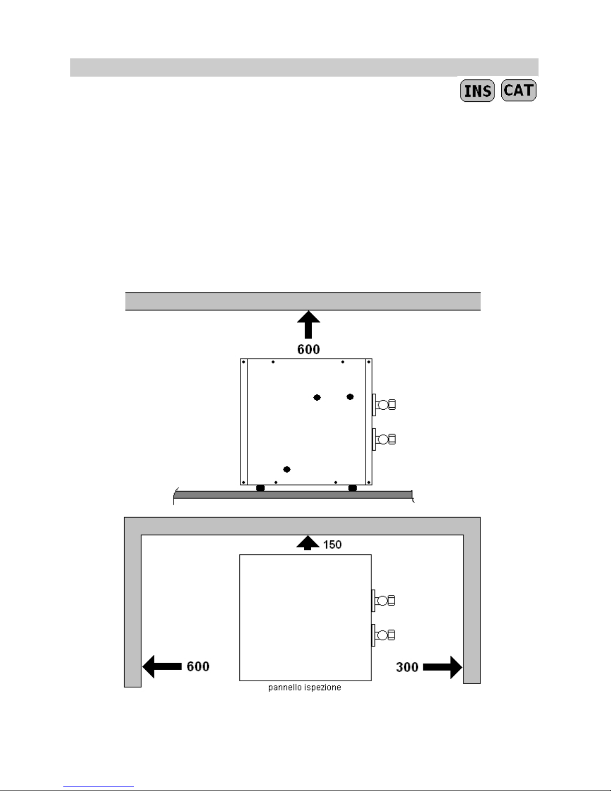
3.1 PLACE OF INSTALLATION
The place of installation must be agreed upon with the custo mer, paying attention to the following:
· The unit must be placed in a suitably sized space whose dimensions conform to existing regulations in the
country where it will be installed.
· The condensing unit should not be installed outdoors.
· The surface on which it will be placed must be able to support its weight.
· In case of multiple installations (2 or more IDRA), DO NOT STACK the condensing units.
· Proper installation should allow authorised personnel to intervene in case of maintenance, in an easy manner,
observing the safety distances between units and other equipment indicated below:
7

3 - INSTALLATION
3.2 HYDRAULIC AND REFRIGERATION CIRCUITS
The installer is responsible for the correct selection and application of components according to current national
standards and as recommended below.
3.3 HYDRAULIC COMPONENTS
The hydraulic connections are made on the fittings located on the right side of machine.
The hydraulic connections are distinguished by labels that indicate the flow: WATER INLET AND OUTLET
Provide and interception tap on the water inlet, use piping with an internal diameter that corresponds to the
diameter of the condensing unit's fittings because otherwise operation problems may result (the guarantee is
voided if improper piping is used).
WARNING: ALWAYS MOUNT THE INSPECTION FILTER ON THE WATER INLET
AND ENSURE THE CORRECT POSITIONING OF THE FILTERING UNIT
RESPECT MINIMUM DIAMETERS REQUIRED ON THE UNIT, CHECK THE WATER SUPPLY FLOW.
3.4 REFRIGERATION CONNECTIONS
The refrigeration connections are made on the fittings located on the right side of the unit. The connections on
the refrigeration lines are "flare” connections.
3.5 CONNECTIONS BETWEEN THE EVAPORATOR AND CONDENSING UNITS
The indoor unit must be connected to the condensing unit via Flare connections with a refrigerator quality
copper pipe at the ends of flare nuts and insulated along the entire length. It is absolutely necessary to respect
the
diameters
provided
on
IDRA INVERTER units
otherwise
the
guarantee
will
be
voided.
If
evaporator
units
with
refrigeration fittings different than those on the IDRA INVERTER units are used, use dedicated reduction connections
(attention: mount these fittings on the evaporator unit).
3.6 PIPE PREPARATION
Use only refrigeration quality copper pipes with a suitable diameter for each model. The gas and liquid
pipes must absolutely be insulated with insulation that has a minimum thickness of 6mm.
Insert the flare nuts on the pipe ends before preparing them with a countersink tool. The pipes, separately
insulated with the relative fittings can later be bound to the condensing unit's evacuation pipe and the
electrical cables using clamps.
3.7 PIPE ROUTE
The radius of curvature of the pipes must be equal or greater than three and a half times the diameter of the
pipe axis. Do not bend the pipes more than 3 times consecutively and not make more than 10 curves on the total
length of the connection. If there is more than a 5m difference between the evaporator unit and condensing
unit, a siphon must be placed at every 3 m. The siphon must have a radius of curvature that is as narrow as
possible.
3.8 AIR EXTRACTION IN REFRIGERATION AND
EVAPORTATOR PIPES
The R410a load is only contained in the condensing unit. The inner unit contains a small quantity of neutral gas.
Therefore, after having made the connections, it is necessary to extract the air contained in
these connections and in the inner units.
WARNING: IT IS NECESSARY TO USE A COUNTER KEY TO TIGHTEN THE VALVES.
8

3 - INSTALLATION
3.9 ASSEMBLY PROCEDURE
The IDRA INVERTER condensing unit MUST BE INSTALLED in an accessible place that allows for safe technical interventions;
if this is not the case, the Technical Assistance Centre may refuse intervention.
THE IDRA INVERTER CONDENSING UNIT MUST NOT BE INSTALLED OUTDOORS BECAUSE DURING
WINTER MONTHS ITS HYDRAULIC CIRCUIT MAY BE DAMAGED
ALWAYS PUT AN INSPECTABLE FILTER ON THE WATER INLET (500 micron mesh).
Connect the connection pipes to the condensing unit and the internal unit.
Connect the vacuum pump to the fitting (suction), start it up, and make sure that the indicator pointer goes
down to 0.1 Mpa (-760 mm Hg). Before disconnecting the vacuum pump ensure the vacuum indicator is stable
for >15 minutes.
Close the service valve and disconnect the vacuum pump.
Remove the caps from the "GAS" and "LIQUID" valves and open them with a hexagonal key to release the
R410a contained in the IDRA INVERTER, then put the caps back on.
Check that the connections are sealed properly .To do this use an electronic leak detector or a spray solution
for leak detection.
3.10 ADJUSTING THE REFRIGERANT LOAD
Depending on the connection length of each route, it may be necessary to top up the R410a load (the condensing
units are pre-filled with a line of 5 metres). This operation must be carried out by a qualified person who is an
expert in refrigeration. The complete load is introduced via the service valve or via the condensing unit's Flare
(large fitting). If the refrigerant line is less than 5 m “discharge" the quantity of excess refrigerant. All operations
involving refrigeration circuits require observing recommendation regarding the disposal of R410a
(according to local laws in force).
*See the technical data sheet.
3.11 ELECTRICAL CONNECTIONS
A proper and effective earthing connection is mandatory
;
the manufacturer is not responsible for damages caused by inappropriate or insufficient connections.
Electrical connections must be made respecting the following:
•
Use cables which are compliant with the laws in force in the different countries.
•
Follow the order of connection for the phase, neutral and earthed conductors.
•
Install a suitable protection and electric energy sectioning device with a delayed curve, a contact opening of
•
at least three millimetres and an adequate interruption and differential protection power.
9

3 - INSTALLATION
If the unit powering is three-phase, make sure to follow the exact sequence of the phases.
The supply voltage of the condensing unit must have a value between ± 10% of the value
indicated on the manufacturing data plate. If this is not followed, contact the local supplier of electric power.
In the case of three-phase power, the imbalance between the three phases should not exceed 3%.
Putting electrical connection cables inside the condensing unit in any part not approved by the
manufacturer is prohibited.
The power cable must be passed through one the holes with a rubber fairlead located on the left side of the
machine. The electrical connections are made on the terminal board located inside the components and
electrical compartment on the rear of the inspection panel.
Connect the cable to the terminals inside the electrical panel.
Absolutely avoid direct contact with metal parts.
Make sure, after the condensing unit has been operating for about 10 minutes that the screws on the power
terminal are closed.
Warning: Verify compatibility when using evaporator units NOT PROVIDED BY T.P.I.
The
connection between the
ventilation and
condensing
unit
requires
a
pentapolar
cable
(5 X
1.5
mm
q).
Power the IDRA unit with a cable suitable to the power consumption and install a properly sized general isolator
switch (in compliance with laws in force).
10
3 – INSTALLATION iCFV-xxC/H
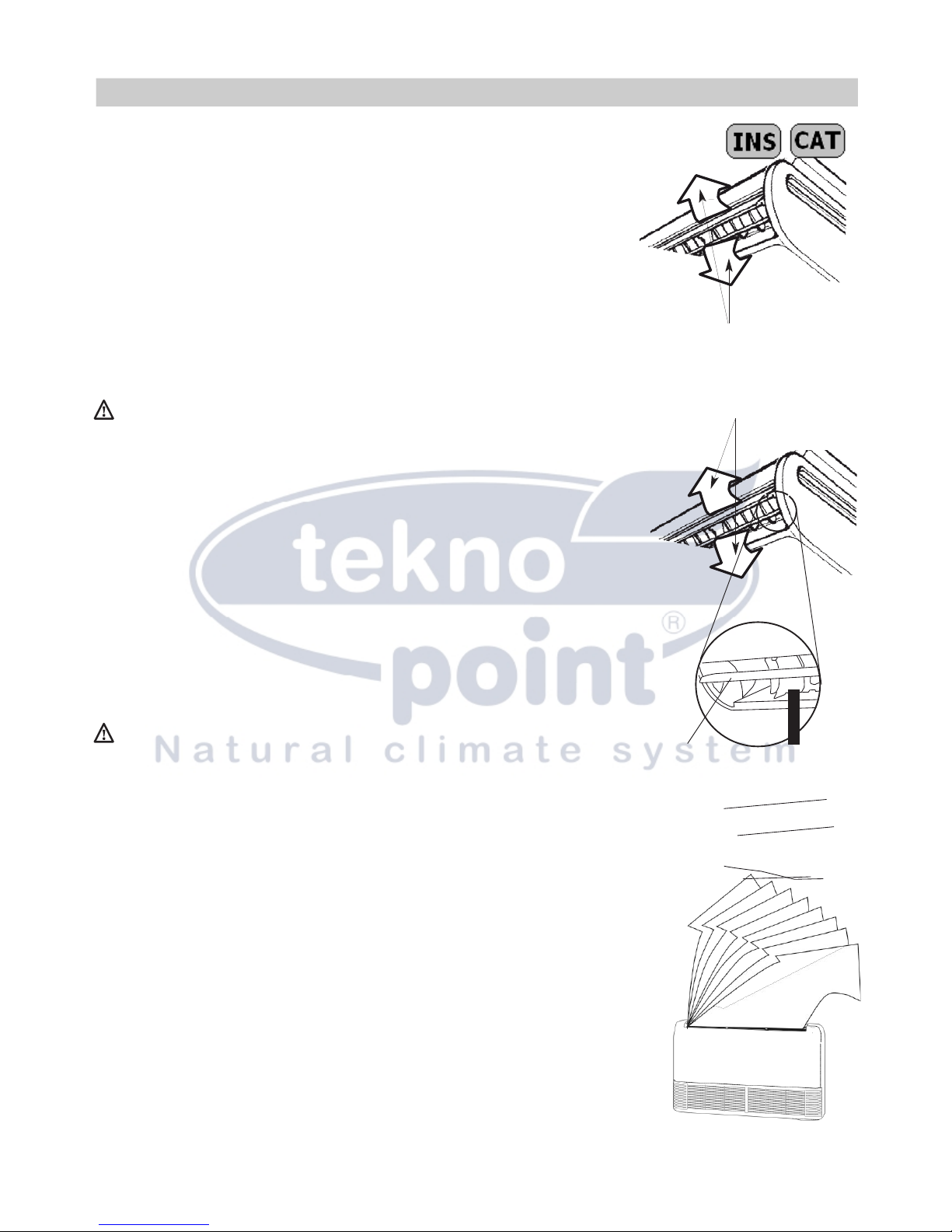
ADjUSTING
THE DIRECTION OFTHE
AIR FLOW
When you press the SWING vertic al bu t ton , the o sc ill ating v er ti ca l mov e ment o f the
directional flaps is enabled, when you press the SWING horizontal button ,the
oscillating
horizontal movement of the directional flaps is enabled To ensure the uniform
diffusion of
air throughout the room.
Press the AIR DIRECTION button again and the oscillating movement of the flaps stops in the
desired position and the air flow is directed in one direction only:
-we recommend you direct them upwards in cooling mode(to avoid having the direct flow of cool air).
-we recommend you direct them downwards in heating mode(as hot air tends to rise).
ATTENTION
-Unplug the appliance or switch off the dedicated switch before performing any operations
(risk of personal injury from electrocution).
-Do not direct the air flow directly towards people, artworks or animals (risk of causing
damage to things and personal injury to people’s skin)
-Do not insert or attempt to insert your fingers or various objects in the internal and external unit
air outlets and in the inlet grilles (risk of personal injury from cuts).
-Do not touch the air conditioning unit with wet hands (risk of electrocution).
ADVICE ON ENERGYSAVINGS
-Do not programme too high a temperature (in heating mode) or too low a temperature
(in cooling mode).
-Avoid installing the internal/external units in places directly exposed to sunlight(this
could prevent the appliance from operating at its best).
-Avoid opening and closing doors and windows too frequently, as the ongoing heat exchange
with the outside hinders the operation of the air conditioning unit.
-Use the “Timer” for the timed starting of the appliance to prevent the appliance from
opera- ting unnecessarily while you are out.· Use the “SLEEP” function at night.
ATTENTION
-Do not attempt to perform maintenance operations requiring the opening of the appliance
yourself: the presence of live elements and the gas contained n the cooling circuit
make these operations particularly dangerous (risk of personal injury from electrocution
and cold burns).
-When moving home, contact an authorised specialist.
Note:
-In cooling mode, you may detect a slight mist coming out of the Internal Unit for a few
seconds: this is completely normal and due to the difference in temperature between
the air exiting the appliance and the air inside the room.
-During operation, you may hear a noise similar to the flowing of water: this is completely
normal, owing to the liquid refrigerant flow ing throug h t he pipin g.
-When the air conditioning unit starts or stops, especially in heating mode, you may hear
a little creaking: this is due to the thermal expansion of the parts making up the appliance.
11
 Loading...