

Climatizzatore Monosplit
Monosplit air conditioner
Manuale installatore
Installation manual
BA Series
I prodotti elettrici ed elettronici di eventuale scarto dovranno essere disposti con i normali rifiuti domestici, ma
smaltiti a norma di legge RAEE in base alle direttive Europee 2002/96/CE e successive modifiche 2003/108/CE,
informandosi presso il Comune di residenza o presso il rivenditore nel caso in cui il prodotto venga sostituito
con uno analogo.
Possible wasted electrical or electronic devices/products should not be located together with normal
domestic waste, but disposed according to the current WEEE law in compliance with the European
Directive 2002/96/EC and following modifications 2003/108/EC. Please inform yourself at your local

ITALIANO
Note per il funzionamento
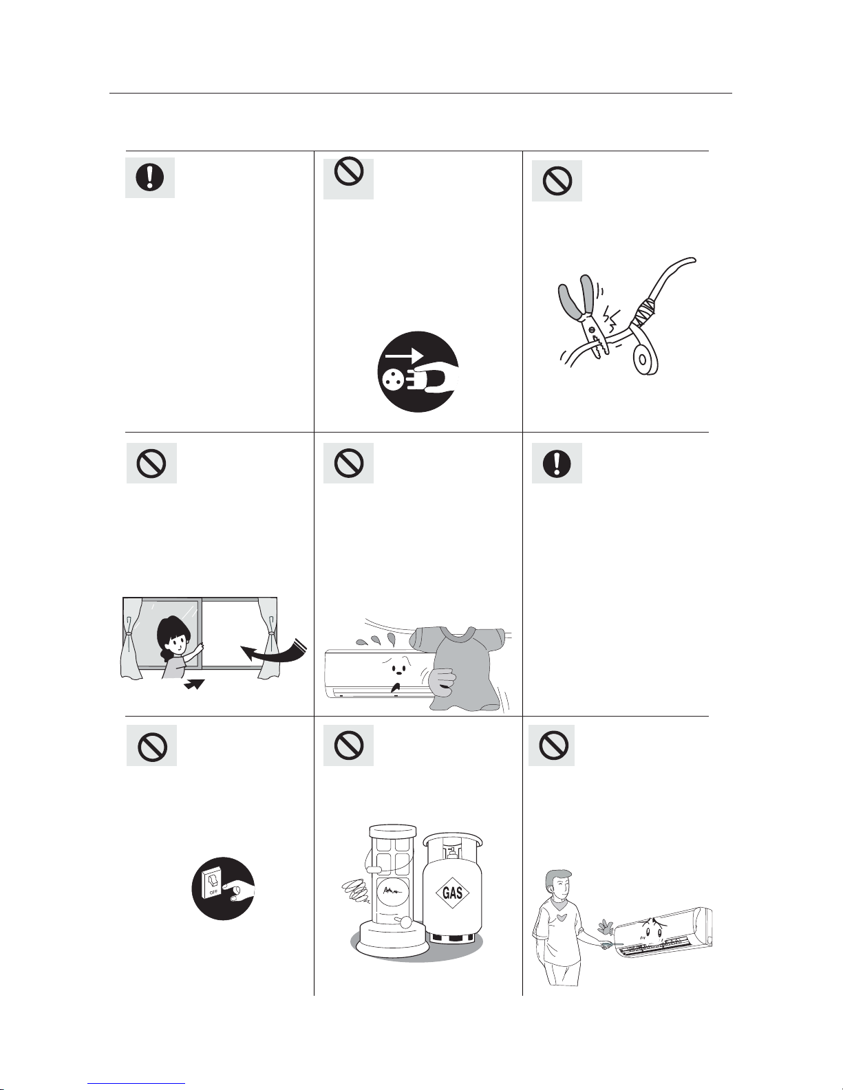
Può provocare surriscaldamento o incendio.
Spegnere l'alimentazione e
contattare il centro
assistenza se si avverte
odore di bruciato o fumo.
Possono verificarsi cortocircuiti.
Possono verificarsi incenti o
esplosioni.
Non bloccare la presa d’aria e
le uscite delle unità interna ed
esterna.
Può diminuire l’effcienza del
condizionatore o verificarsi
malfunzionamenti.
Quando la tensione è molto
alta, i componenti possono
venire facilmente danneggiati, quando è molto bassa,
il compressore vibra fortemente e quindi il sistema
refrigerante può danneggiarsi assieme al compressore e i componenti elettrici;
la tensione deve rimanere
costante e non subire forti
fluttuazioni.
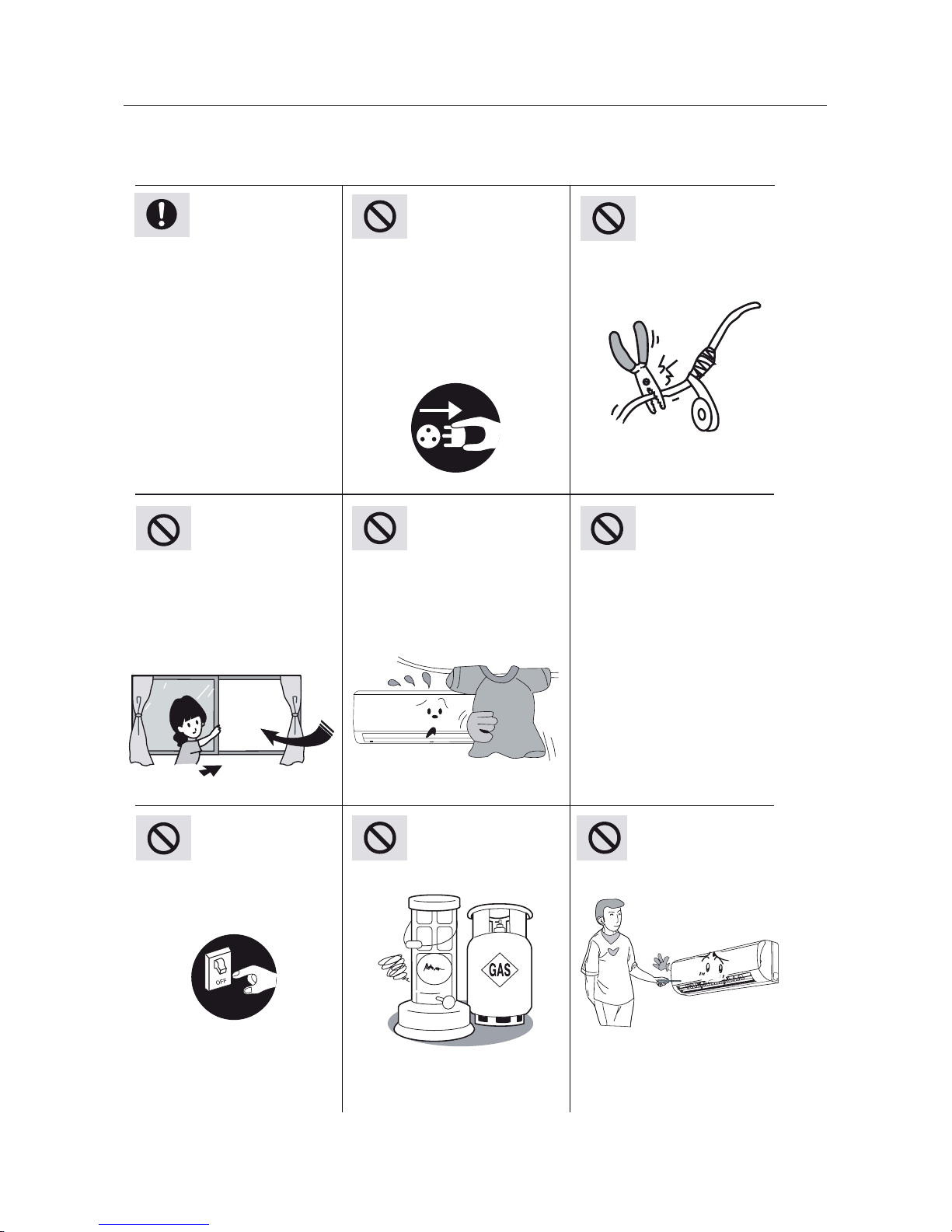
Assicurarsi di togliere
l’alimentazione quando il
climatizzatore non viene
utilizzato per un tempo prolungato, altrimenti l’accumulo di
polvere può provocare
surriscaldamenti e incendi.
Mai accoppiare il cavo di
alimentazione o usare prolunghe.
Non lasciare finestre e porte
aperte per lungo tempo
mentre il condizionatore è in
funzione altrimenti diminuisce
l’efficienza del condizionatore.
Il gruppo di alimentazione
deve adottare un interruttore
di protezione.
Si prega di non accendere o
spegnere l'unità frequentemente, per non danneggiare
l’unità.
Non tentare di riparare il
condizionatore da soli.
Tenere i liquidi infiammabili ad
oltre 1 m dall’unità .
Leggere con cura questo manuale per un corretto utilizzo del condizionatore.
4
Note per il funzionamento
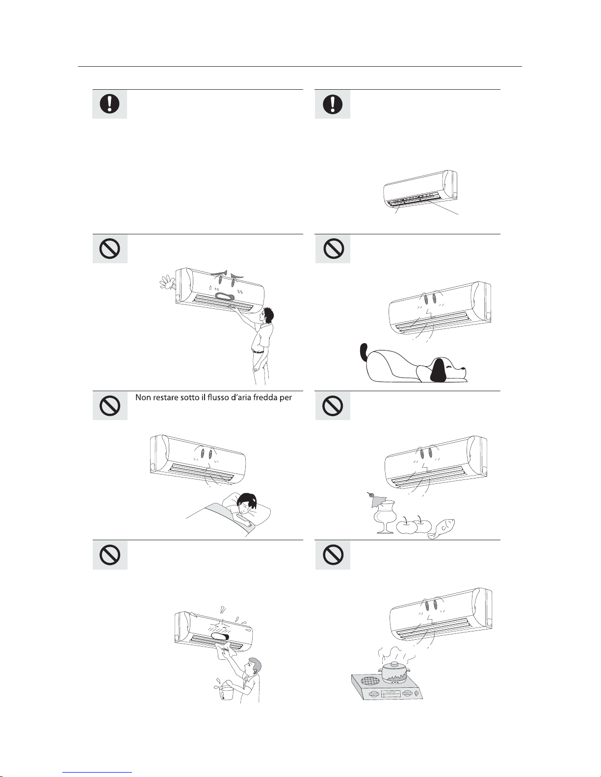
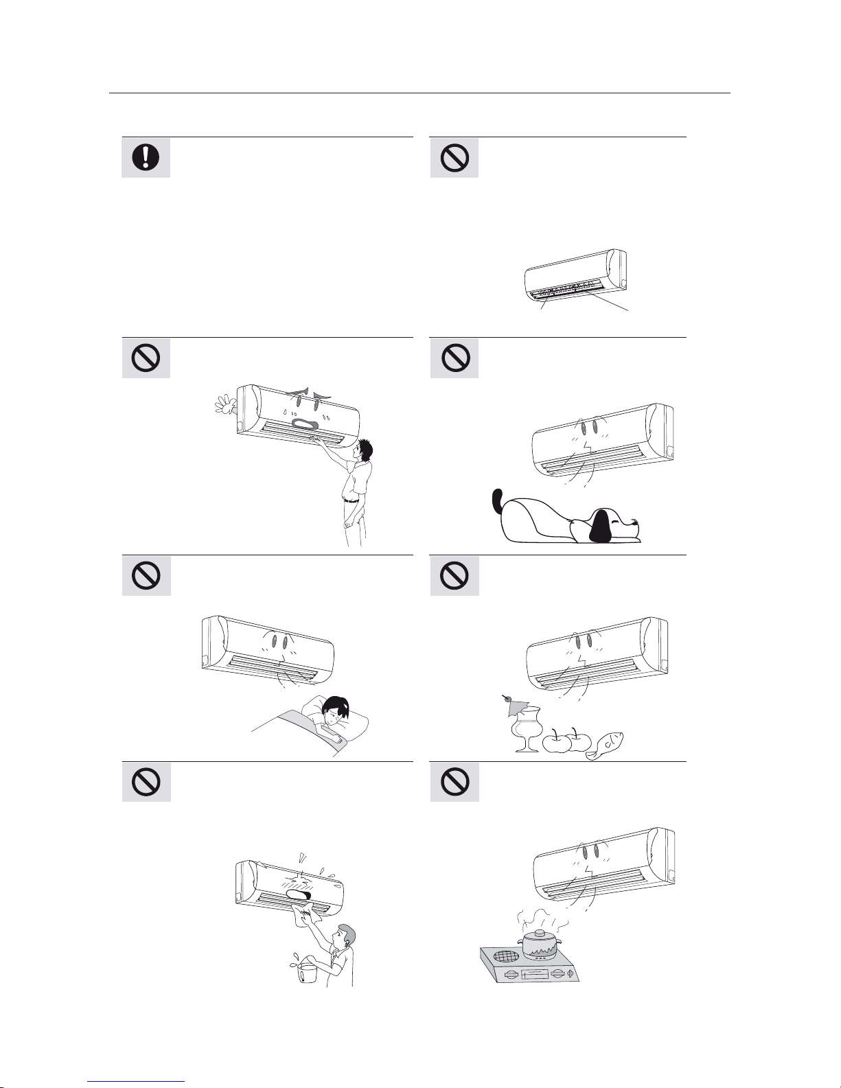
Aletta
Guida aletta
Spruzzare l'acqua sul condizionatore può
causare una scossa elettrica e un malfunzionamento.
Non esporre piante o animali direttamente sotto il flusso d’aria.
Non utilizzare il condizionatore per
altri scopi, come per asciugatura di
vestiti, conservazione alimenti, ecc.
Si prega di non tagliare o danneggiare i
cavi di alimentazione; se sono danneggiati è consigliabile di chiamare del
personale qualificato per la sostituzione.
Non inserire le mani o stecchi nella
presa o nell'uscita d'aria.
lungo tempo per evitare problemi di salute
Per regolare il flusso dell’aria regolare
le alette del condizionatore premendo
il tasto SWING sul telecomando.
Non disporre il condizionatore vicino
a sorgenti di calore quali cucina ed
elettrodomestici.
5
9
Nomi e funzioni dei componenti
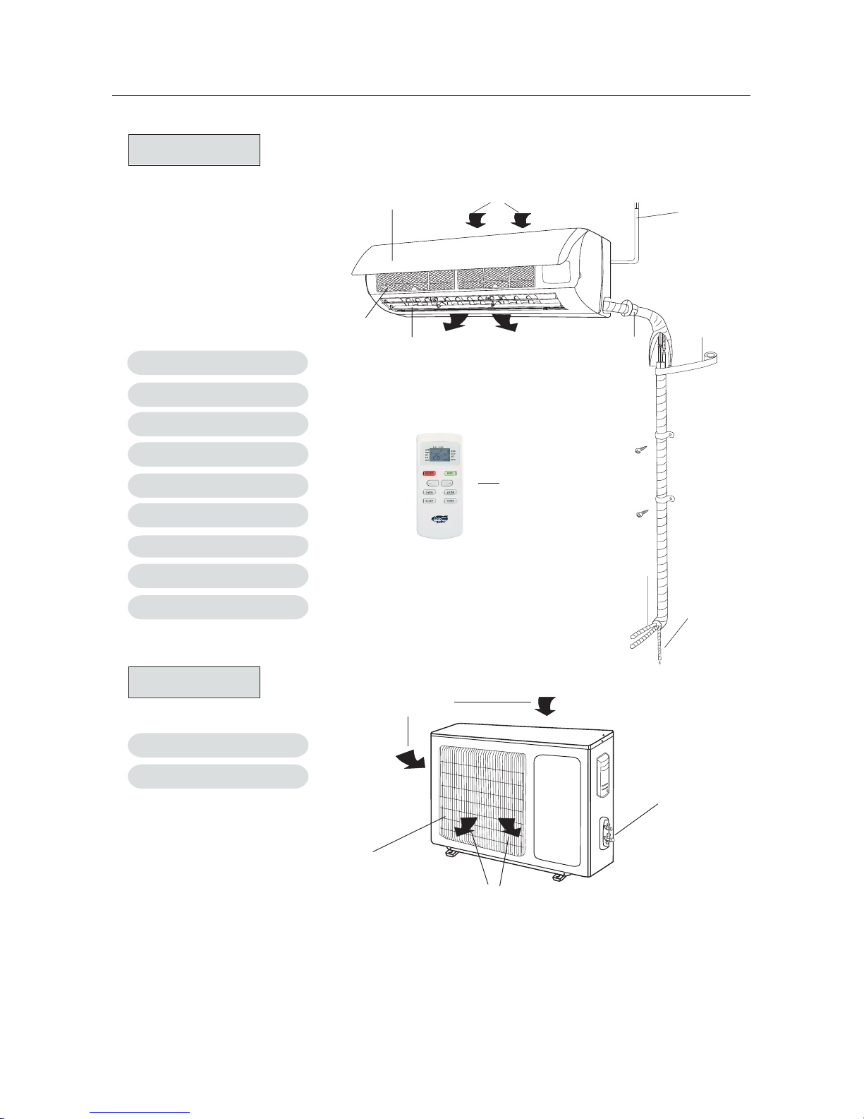
Unità interna
Unità esterna
(1) Interruttore manuale
(5) Finestra ricezione
(2) Pannello frontale
(3) Filtro
(4) Guida aletta
(6) Nastro fissazione
(7) Cavo connessione
(8) Tubo drenaggio
(9) Telecomando
(1) Griglia uscita aria
(2) Valvola
Nota: le suddette figure sono solamente un esempio illustrativo, le unità acquistate
possono essere apparentemente diverse.
Ingresso aria
Uscita aria
Air in
Air out
2
3
1
4
5
6
7
8
1
2
6
Italiano
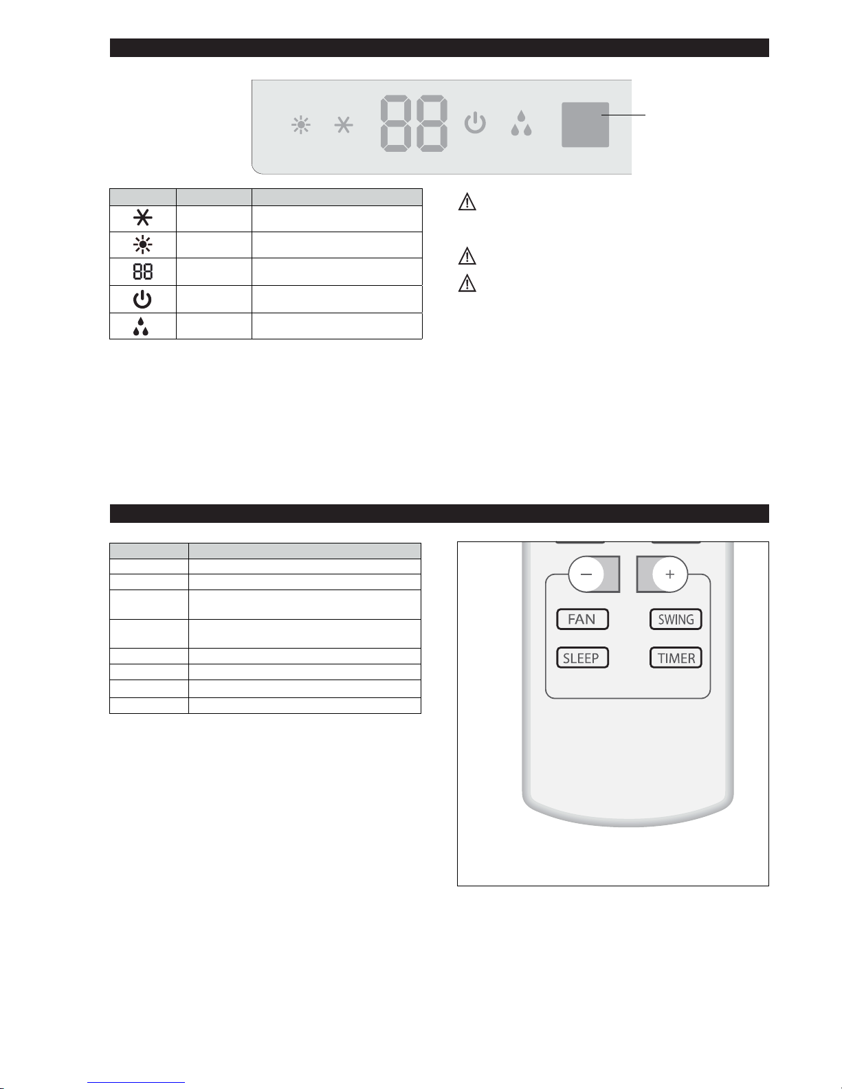
FUNZIONAMENTO E DISPLAY
TELECOMANDO
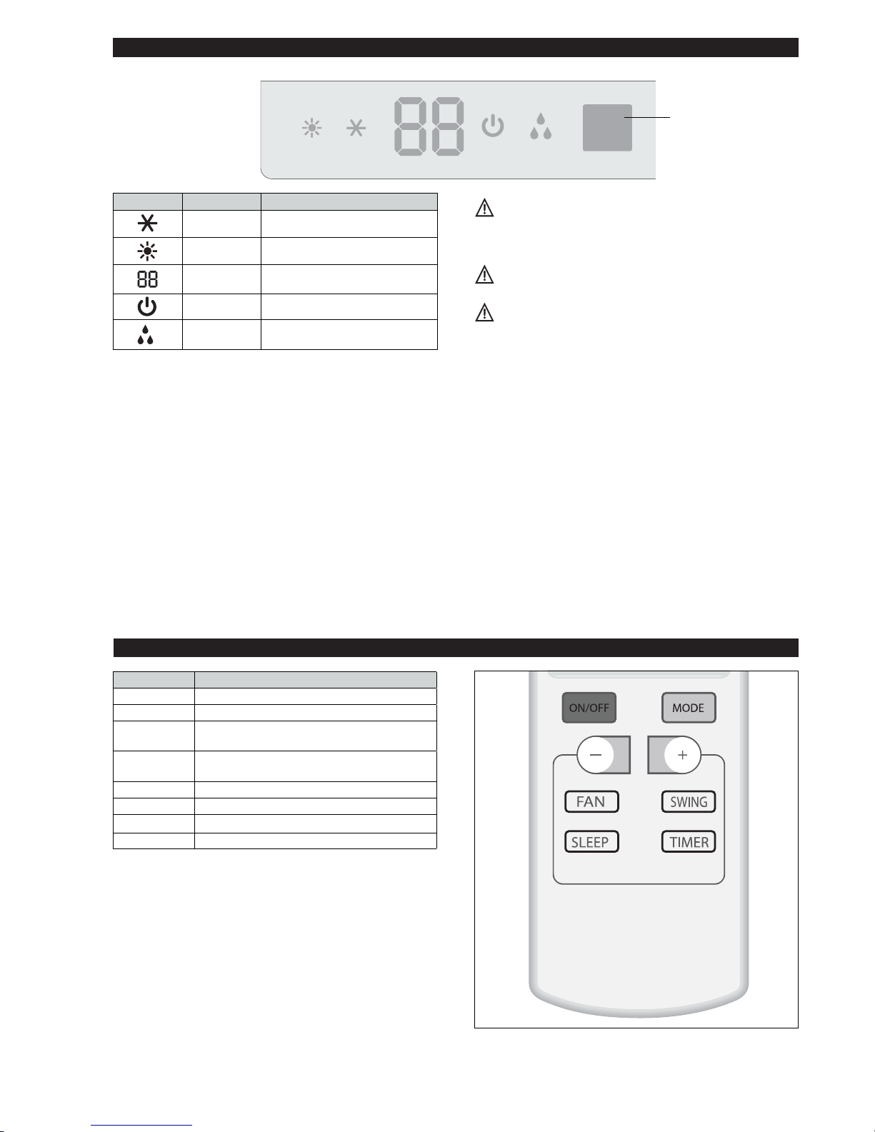
Led Funzione
COOL Modalità raffreddamento attiva
HEAT Modalità riscaldamento attiva
SET
Indica la temperatura impostata in °C
ON-OFF Indica il funzionamento
DRY
Modalità deumidificazione
attiva
La forma e la posizione di interruttori e indicatori
può variare in funzione del modello, ma il loro
funzionamento rimane uguale.
Presenza di tensione a griglia aperta.
In caso di perdita del telecomando operare come
segue:
- Quando l’unità è spenta premere il tasto RIAVVIO
AUTOM ATIC O p resente sull’unità per attivare il
climatizzatore; il condizionatore si setterà in modalità
di raffreddamento, deumidificazione o riscaldamento
a seconda delle condizioni ambientali, per garantire la
massima situazione di comfort.
- Per spegnere l’unità premere nuovamente il tasto
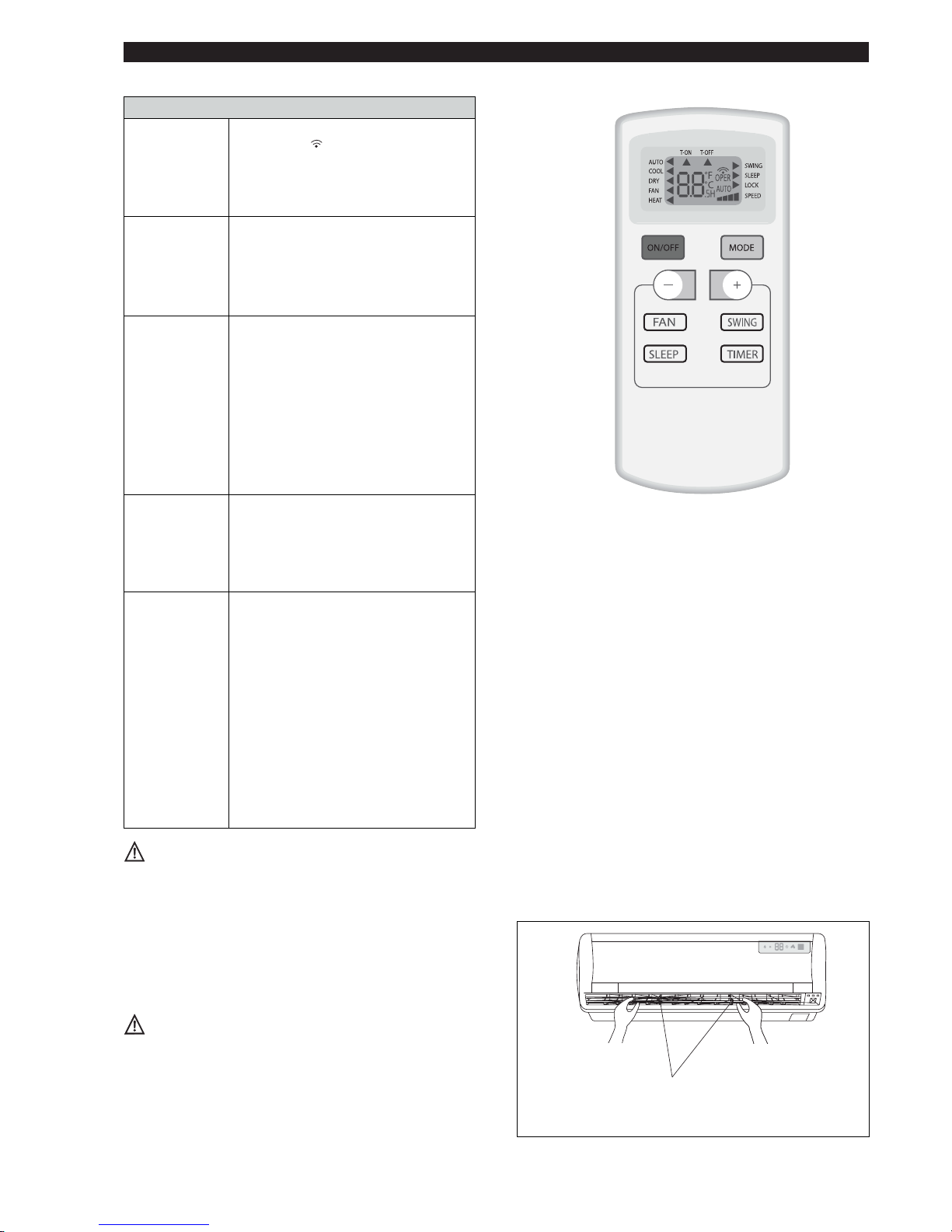
Tasto Funzione
ON/OFF Accensione/Spegnimento
MODE Seleziona le modalità di funzionamento
( - ) DOWN
Diminuisce la temperatura e il TIMER di 1
unità
( + ) UP
Aumenta la temperatura e il TIMER di 1
unità
FAN Seleziona la velocità del ventilatore
SLEEP Avvia la funzione notturna
SWING Regola la posizione delle alette.
TIMER Imposta il TIMER
Ricevitore
segnale
7
Utilizzare 2 batterie R03 AAA (1,5 V). Non utilizzare
batterie ricaricabili.
Sostituire le batterie usate con batterie nuove dello
stesso tipo quando il display non è più leggibile.
Le batterie del telecomando devono essere smaltite
in modo appropriato secondo le leggi vigenti nei
diversi paesi.
Come usare il telecomando
Per mettere in funzione il climatizzatore, puntate il telecomando verso il ricevitore segnale. Il telecomando funzionerà fino ad una distanza massima di 8 metri dall’unità
interna.
Riporre il telecomando ad una distanza di almeno 1m
dal televisore o da altri apparecchi elettrici.
Ricevitore segnale
Il display del telecomando rimane attivo anche quando l’unità non è in funzione.
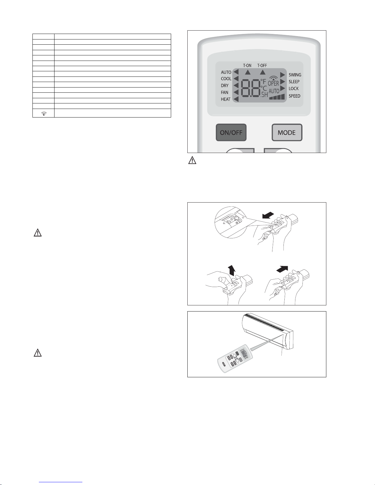
DISPLAY del telecomando
Simboli degli indicatori sul display a cristalli liquidi:
AUTO
Indicatore modalità auto
COOL
Indicatore modalità raffreddamento
DRY
Indicatore modalità deumidificazione
FAN
Indicatore modalità ventilazione
HEAT
Indicatore modalità riscaldamento
SWING
Indicatore deflettore aria attivato
SLEEP
Indicatore modalità notturna
LOCK
Indicatore blocco telecomando
SPEED
Indicatore di velocità: super min, min, med, max
T-ON
Indicatore Timer ON
T-OFF
Indicatore Timer OFF
°F
Indicatore gradi Fahrenheit impostati
°C
Indicatore gradi Celsius impostati
.5H
Indicatore impostazione timer
Indicatore ricezione segnale
8
Italiano
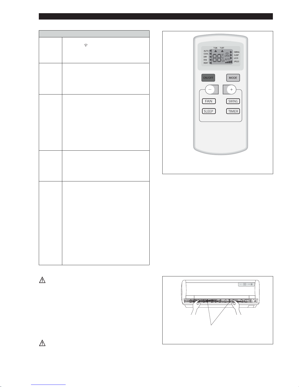
Modalità di funzionamento
ON/OFF
Accensione/spegnimento/Stand-by.
Il simbolo
comparirà sul display del telecomando quando il climatizzatore è acceso.
Quando viene spento o acceso, le funzioni
Timer e Sleep vengono cancellate.
FAN
(Modalità
ventila-
tore)
Ogni volta che viene premuto il pulsante
FAN, la velocità viene modificata in sequenza
tra: AUTO - SUPERMIN - MIN - MED MAX. Selezionando la modalità AUTO, il
climatizzatore sceglierà automaticamente la
velocità di ventilazione.
SWING
Regolazione del flusso dell’aria. Premendo
il pulsante “SWING” le alette di regolazione
del flusso dell’aria iniziano ad oscillare
automaticamente; premendo nuovamente
il pulsante “SWING” le alette si fermano.
L’avviamento di questa funzione, se attivata in
modalità HEAT, sarà leggermente ritardata per
assicurare una immediata fuoriuscita dell’aria
calda per offrire da subito una piacevole
temperature in uscita (funzione Hot-Start).
MODE
Selezione della modalità di funzionamento.
Ogni volta che viene premuto il pulsante MODE
(MODALITÁ), la modalità di funzionamento
viene modificata in sequenza tra: AUTO -
COOLING - DRY - FAN - HEATING.
La modalità di default è AUTO.
( - ) , ( + )
Down/Up
Impostazione della temperatura.
Premere una volta per alzare (+) o abbassare
(-) la temperatura impostata di 1°C.
Gamme di regolazioni di temperatura disponibili:
- RISCALDAMENTO 16°C ~ 30°C
- RAFFREDDAMENTO 16°C ~ 30°C
- DEUMIDIFICAZIONE 16°C ~ 30°C
- VENTILAZIONE 16°C ~ 30°C
Impostazione del timer.
Premere una volta (+) per aumentare
l’impostazione di 0,5h o (-) abbassare
l’impostazione di 0,5h.
Non ruotare manualmente le alette per l’orientamento
dell’aria in verticale, perché ciò potrebbe provocare un
cattivo funzionamento. Se questo avviene, spegnere
innanzitutto l’apparecchio, quindi scollegarlo e ricollegarlo all’alimentazione.
Cursori di regolazione delle alette per
l’orientamento dell’aria in orizzontale.
Regolazione del flusso d’aria orizzontale (manuale)
Per cambiare l’angolazione del flusso d’aria, ruotare i cursori di regolazione delle alette per l’orientamento in orizzontale dell’aria in uscita come illustrato.
Nota: l’unità illustrata può essere diversa dal climatizzatore
da voi acquistato.
Questa operazio ne deve essere effettuata con
l’apparecchio spento.
All’avvio l’apparecchio entrerà nell’ultima modalità
selezionata prima dello spegnimento.
9
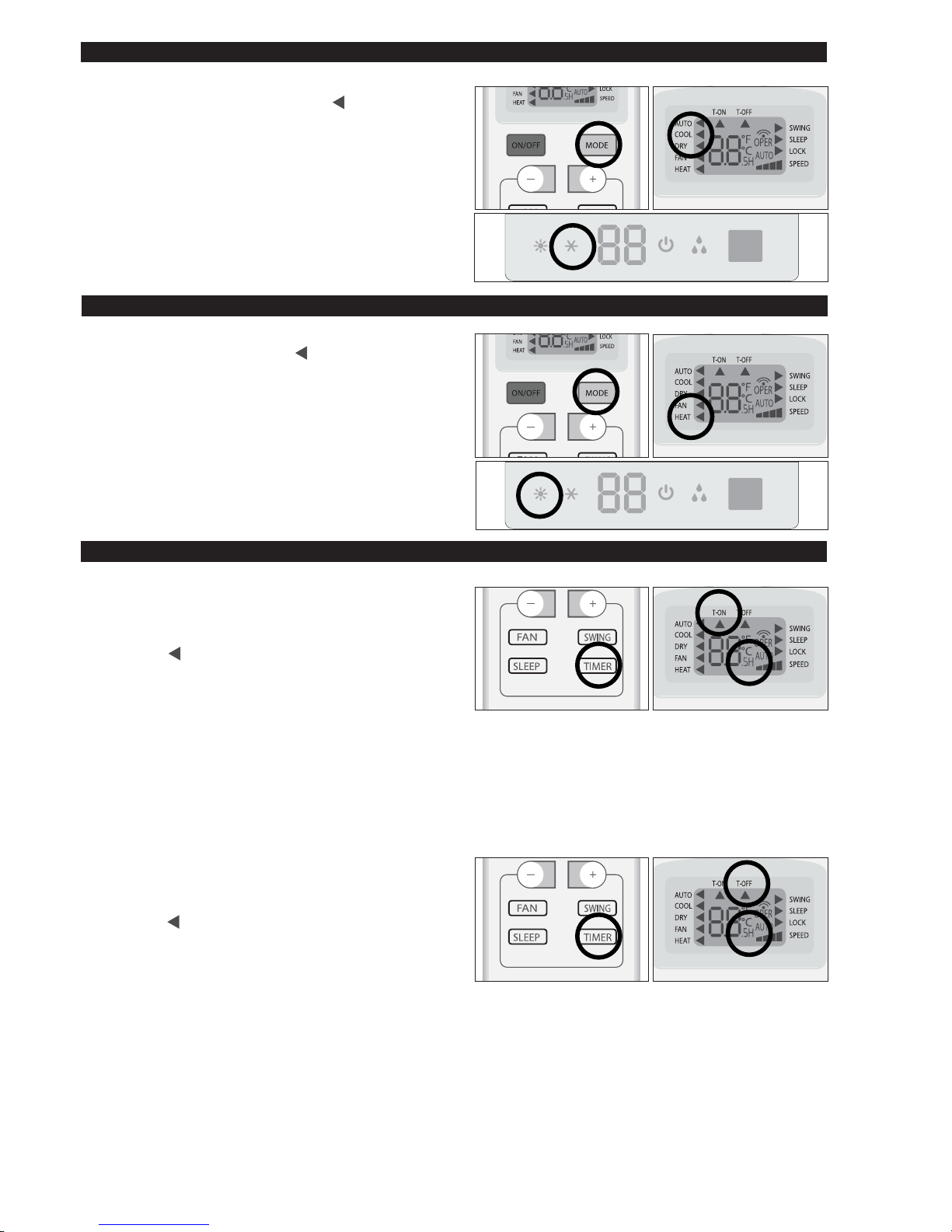
MODALITA' TIMER
MODALITA' RISCALDAMENTO
MODALITA' RAFFREDDAMENTO
Per attivare la funzione riscaldamento (HEAT) premere il tasto
MODE fino a visualizzare il simbolo ( ) sul display a fianco
della scritta HEAT.
Per modificare il valore di temperatura agire sui tasti (+) UP e
(-) DOWN. Ad ogni pressione dei tasti, il valore della temperatura impostata aumenta o diminuisce di 1°C.
Per attivare la funzione raffreddamento (COOL) premere il
tasto MODE fino a visualizzare il simbolo ( ) sul display a
fianco della scritta COOL.
Per modificare il valore di temperatura agire sui tasti (+) UP e
(-) DOWN. Ad ogni pressione dei tasti, il valore della tempera-
tura impostata aumenta o diminuisce di 1°C.
Accensione automatica
Per impostare l’accensione automatica del climatizzatore,
procedere come riportato di seguito:
- A macchina spenta, premere il tasto TIMER.
Il simbolo (
) sotto T-ON e la lettera H lampeggeranno
per 5 secondi.
Durante questo tempo:
- Impostare il periodo di funzionamento agendo sui tasti
(+) UP e (-) DOWN.
Ad ogni pressione dei tasti, il valore cambia di 0,5h (Da
0,5 a 24h).
Se l’impostazione viene accettata il display visualizzerà
il valore di set prima di tornare alla visualizzazione della
temperatura.
Nota: Per eliminare la funzione premere nuovamente il
tasto TIMER.
Spegnimento automatico
Per impostare lo spegnimento automatico del climatizzatore, procedere come riportato di seguito:
- A macchina accesa, premere il tasto TIMER.
Il simbolo (
) sotto T-OFF e la lettera H lampeggeranno
per 5 secondi.
Durante questo tempo:
- Impostare il periodo di funzionamento agendo sui tasti
(+) UP e (-) DOWN.
Ad ogni pressione dei tasti, il valore cambia di 0,5h (Da
0,5 a 24h).
Se l’impostazione viene accettata il display visualizzerà
il valore di set prima di tornare alla visualizzazione della
temperatura.
Nota: Per eliminare la funzione premere nuovamente il
10
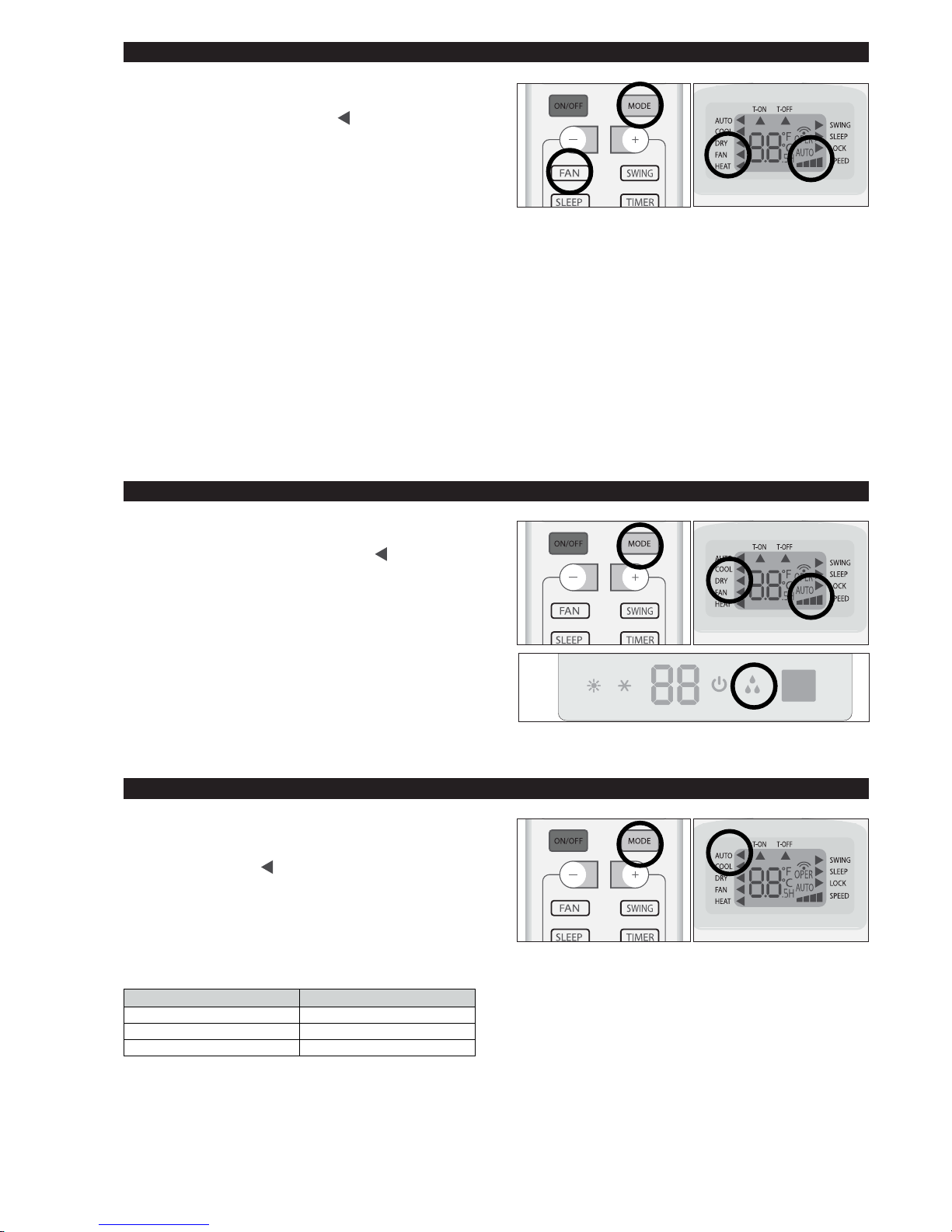
MODALITA' DRY
MODALITA' FAN
Modalità deumidificazione
Per attivare la funzione deumidificazione (DRY) premere il
tasto MODE fino a visualizzare il simbolo ( ) sul display a
fianco della scritta DRY.
L’apparecchio si attiva a seconda della temperatura
ambiente e di quella impostata.
MODALITA’ AUTO
Temperatura ambiente Modalità
circa 22°C RISCALDAMENTO
22~24°C DEUMIDIFICAZIONE
Modalità automatica
Superiore a 26°C RAFFREDDAMENTO
Per attivare la modalità di funzionamento AUTO (automatica) premere il pulsante MODE nel telecomando fino a
visualizzare il simbolo ( ) sul display a fianco della scritta
AUTO.
In modalità AUTO, la velocità del ventilatore, la modalità di
funzionamento e la temperatura, verranno impostate automaticamente per dare un clima confortevole in base alla
temperatura ambiente.
Durante il funzionamento AUTO la temperatura non viene
visualizzata dal display.
Modalità ventilazione
Per attivare la funzione ventilazione (FAN) premere il tasto
MODE fino a visualizzare il simbolo (
) sul display a fianco
della scritta FAN.
Ogni volta che viene premuto il pulsante FAN, la velocità viene modificata in sequenza tra: AUTO - SUPERMIN - MIN
- MED - MAX. Il telecomando inoltre, mantiene in memoria
la velocità impostata nella precedente modalità di funzionamento.
In modalità AUTO, il climatizzatore sceglierà automaticamente la velocità di ventilazione e la modalità di funzionamento (RAFFREDDAMENTO o RISCALDAMENTO).
11
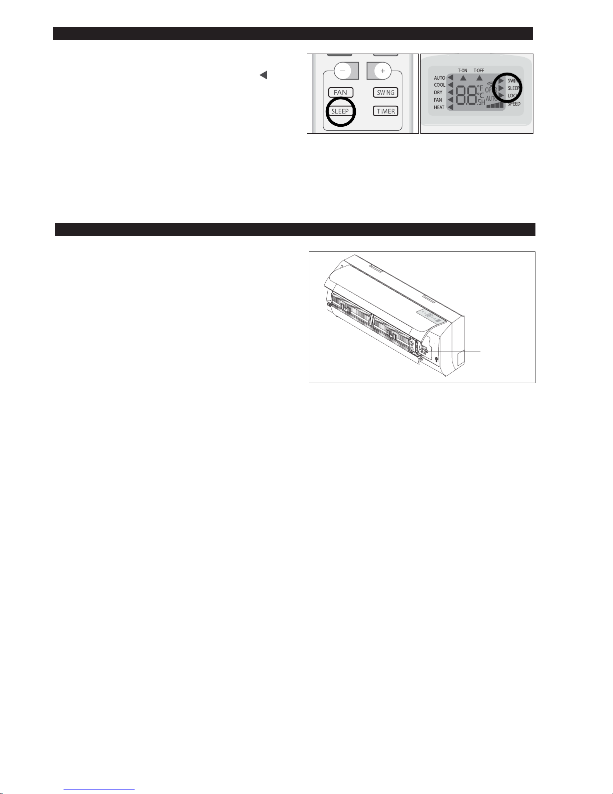
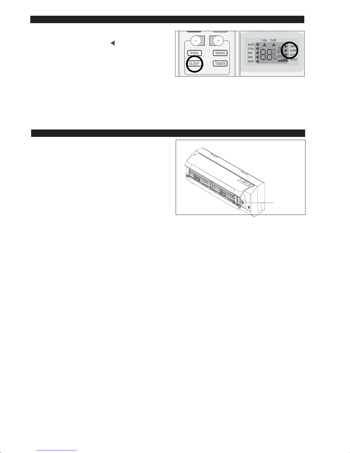
MODALITA' SLEEP
Modalità notturna
Per attivare la modalità notturna nelle funzioni COOL, DRY
e HEAT, premere il tasto SLEEP. Sul display apparirà ( ) a
fianco della scritta SLEEP.
Per disattivare la funzione notturna, premere nuovamente il
tasto SLEEP.
Durante il funzionamento in modalità notturna, la temperatura impostata aumenterà di 1 °C nella prima ora di funzionamento e di 2 °C nella seguente ora e manterrà i 2°C in
più nelle successive ore.
Selezionando la modalità notturna in riscaldamento, la temperatura impostata diminuirà di 1 °C nella prima ora di funzionamento e di 2 °C nella seguente ora e manterrà i 2°C in
meno nelle successive ore, facendo funzionare il ventilatore
Nota: La funzione SLEEP non è disponibile durante il funzi-
onamento in modalità AUTO e FAN.
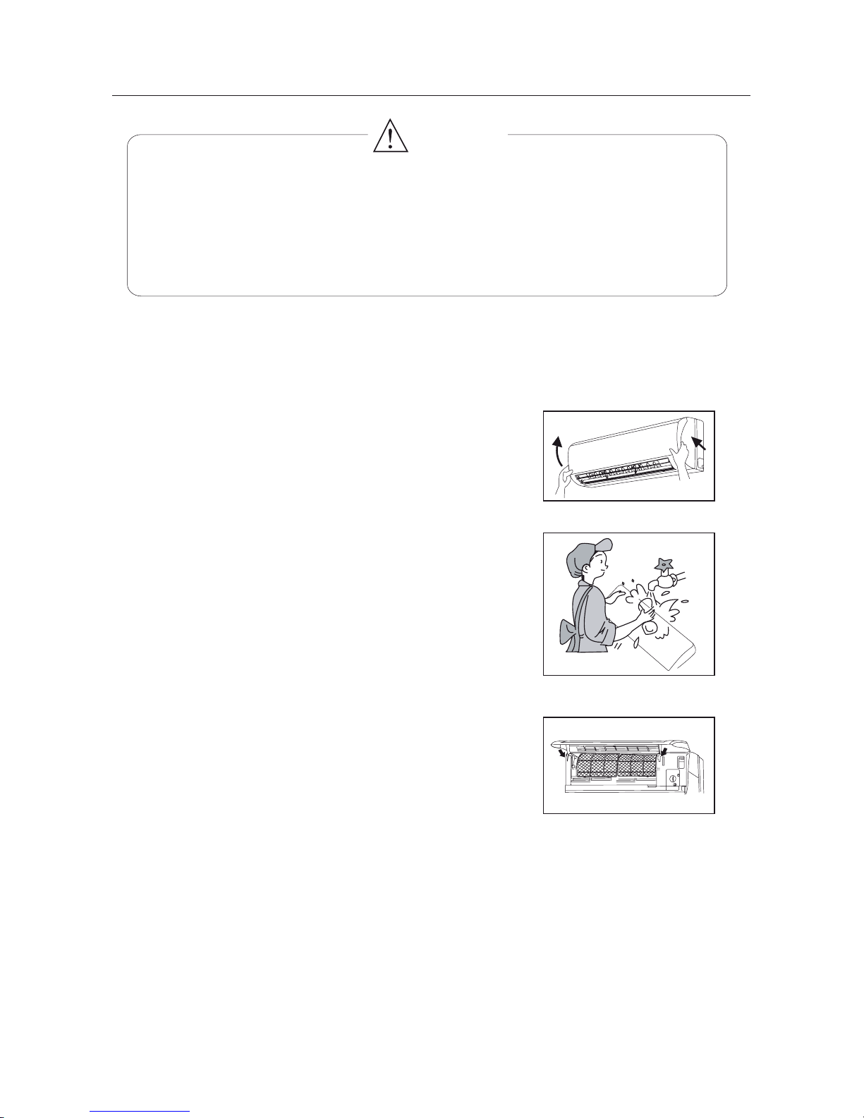
In caso di malfunzionamento o di rottura del telecomando
è possibile attivare o disattivare l’apparecchio attraverso
l’interruttore ausiliario 1.
Attivazione
- Con l’unità spenta premere l’interruttore ausiliario, il condizionatore si avvierà in modalità AUTO
Disattivazione
- Con l’unità accesa premere l’interruttore ausiliario, il
1
12
Pulizia e Manutenzione
ATTENZIONE
Spengnere l'alimentazione ed tirare fuori la spina di alimentazione prima di pulire il
condizionatore per evitare scosse elettriche.
Non usare acqua per pulire l'unità interna per evitare scosse elettriche.
Non usare liquidi volatili (e.s. solvente o benzina) per non danneggiare il condizionatore
e per evitare scosse elettriche. (usare un panno soffice e asciutto per pulire l'unità)
Pulizia del pannello frontale
-1- Sollevare il pannello frontale
Sollevare dalle estremità il pannello
frontale lungo il senso delle frecce fino
a quando non rimane bloccato e tirarlo
fuori.
-2- Lavaggio
Pulire usando una spazzola morbida,
acqua e detersivo neutro, dopo asciugarlo. (nota: Non usare mai l'acqua
ad una temp. superiore a 45°C per
lavare il pannello, per evitare di deformare o perdita di colore del pannello.)
-3- In
stallazione del pannello frontale
Posizionare gli due supporti del pannello frontale nelle scanalature in
direzione delle frecce per chiudere
saldamente il pannello frontale
Nota:
Pulire spesso i filtri dell'aria, perché un filtro sporco può ridurre il rendimento del
condizionatore. Dopo le rimozione, non tocare le alette del ventilatore dell’unità
interna per evitare di ferire le dita della mano.
Pulizia dei filtri( Consigliabileun volta ogni tre mesi)
13

Controlli prima dell'utilizzo
D
E
-1- Tirare giù il filtro d’aria
Tirare verso il basso il fitro d’aria per rimuoverlo completamente.
-2- Pulizia
Usare un aspirapolvere per rimuovere la polvere o lavare i
filtri d'aria in acqua con un detergente neutro. lavarli con
acqua non superiore a 45°C. Risciacquare i filtri e metterli in
ombra per asciugarli.
Nota: Non usare mai l'acqua ad una temp. superiore a 45°C
per il lavaggio, per evitare di deformare o perdita di colori.
-3- Reinserimento dei filtri
Inserire la parte superiore del filtro controllando che alle
estremità entrino nelle apposite corsie e spingere fino a
quando non si blocca.
Posizionare la parte inferiore dei filtri nel loro alloggiamento e
spingere per chiudere il pannello frontale saldamente.
1) Accertarsi che niente ostruisce l’ingresso e l’uscita d’aria.
2) Controllare se il cavo di messa a terra sia collegato corretta-
mente.
3)
Controllare se le batterie del telecomando se sono sostituite
oppure no.
Pulizia e Manutenzione
Manutenzione dopo l’utilizzo
Se pensate di non usare l'unità per almeno un mese:
1) accendete la ventola per almeno mezza giornata per asciugare l'interno dell'unità;
2) fermare il condizionatore e staccare la corrente;
3) rimuovere le batterie dal telecomando.
14
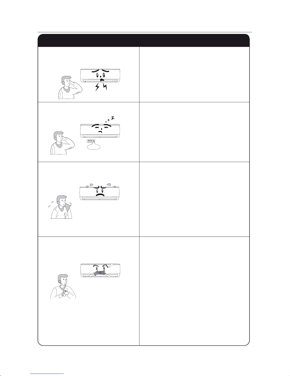
Malfunzionamento
AVVERTENZA
Errore
Causa
waiting
In caso di malfunzuionamento, disalimentare l'apparecchio e contattare il servizio
assistenza più vicino.
Consultare la seguente tabella prima di contattare il centro assistenza.
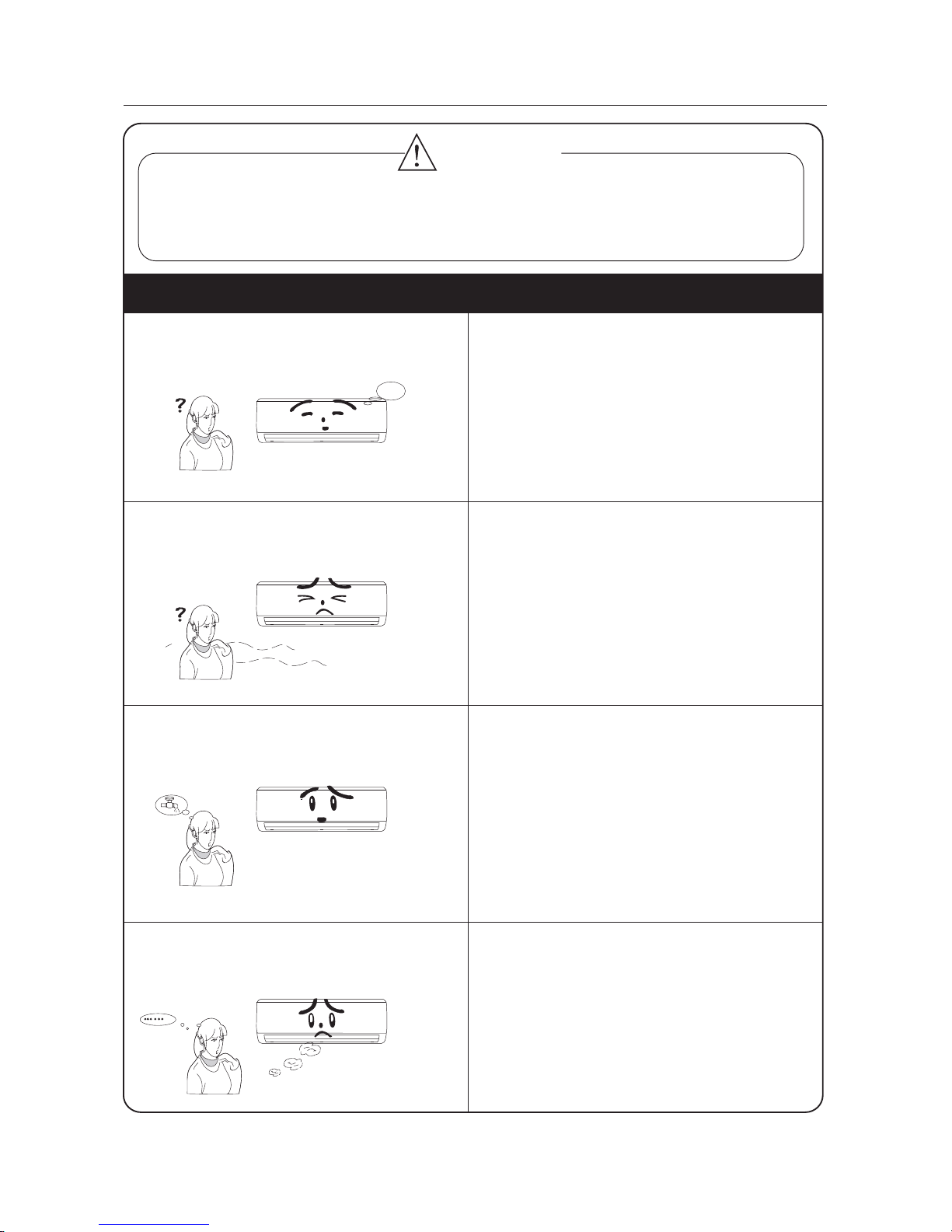
L'unità non parte immediatamente doppo
il riavvio del condizionatore.
Un particolare odore fuoriesce dall'unità
interna.
Si può udire rumori di flusso d’acqua
durante il funzionamento
Ciò è causato dall'unità interna che dà
fuori degli odori pervasi da materiale di
costruzione, da mobilia, o da fumo.
Ciò è causato dal flusso di refrigerante
all’interno dell’unità.
Poiché l'aria della stanza è raffreddata rapidamente da aria fredda
Nebbia generata durante il funzion-
assomiglia alla nebbia.
amento in raffreddamento.
- Il condizionatore impiegherà circa 3
minuti per partire dopo l'arresto.
15

Malfunzionamento
Break off
All’accensione o lo spegnimento di
l’unità un rumore può essere udito.
Ciò è causato dalla dilatazione della plastica causata dalla variazione di temperatura.
Il condizionatore non parte.
- Controllare l'alimentazione che non sia
interrotta?
- I collegamenti sono allentati?
- L'interruttore di protezione di perdita
funziona correttamente?
- La tensione giusta?
- Il TIMER ON è attivo?
- La temp. impostata è adeguata?
- Ingresso o uscita aria sono ostruiti?
- Filtri d’aria sono sporchi?
- Le finestre e la porta sono chiuse?
- Il ventilatore interno è impostato sulla
bassa velocità?
- Ci sono fonti di calore nella stanza?
-
Il telecomando non può essere usato
ogni tanto quando il condizionatore è in
malfunzionamento o quando vengono
cambiate le sue funzioni spesso. In
questo caso, togliere la spina di alimentazione ed inserirla di nuovo per riavviare il condizionatore.
- Il telecomando è nella campo d'azione
all'unità interna?
- Ci sono dell'ostruzione fra il telecomando ed il ricevitore del segnale?
- Sostituire le batterie del telecomando
se la loro tensione non è sufficiente.
Raffreddamento (Riscaldamento) non è
sufficiente.
Telecomando non è disponibile
Errore
Causa
16

INSTALLAZIONE
17

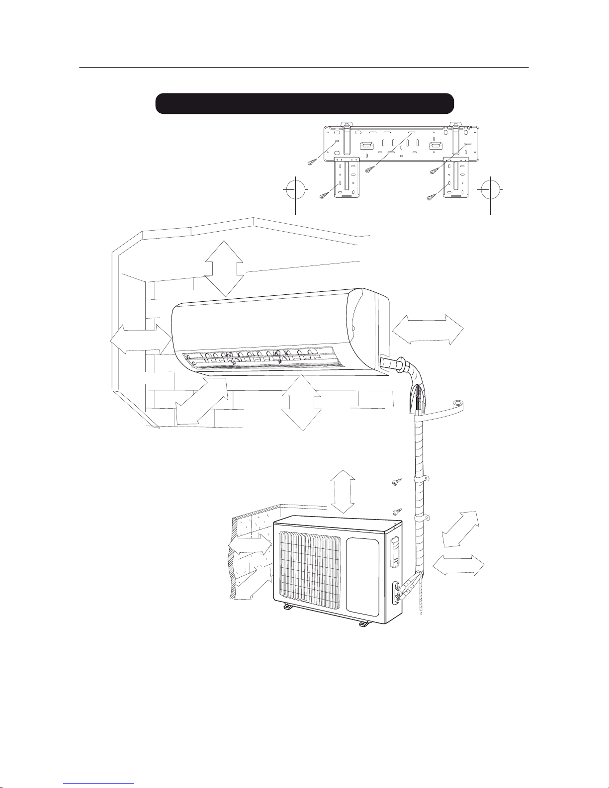
Schema dimensionale
Schema dimensionale
Distanza dal soffitto
Distanza dal pavimento
Distanza dal muro
Distanza dal muro
( > 15 cm )
Lato uscita aria
Distanza dal muro
Distanza dal muro
Lato uscita aria
Lato ingresso aria
( > 15 cm )
( > 15 cm )
( > 300 cm )
( > 230 cm )
( > 30 cm )
( > 50 cm )
( > 50 cm )
( > 200 cm )
18

Installazione dell’unità interna
Installazione della dima
Foro delle tubazioni
1. Fare il foro delle tubazioni leggeremente inclinato al lato esterno del muro.
2. Mentre passe i cavi e le tubazioni di collegamento, inserire la copertina
del foro-tubazioni nel foro per non danneggiareli.
1. Per un buon drenaggio, installare il tubo di scarico condensa verso il basso.
Installazione tubo di scarico condensa
2. Non distorcere o piegare il tubo di scarico condensa o
sommergere la estremità nell'acqua.
3. Coprire il tubo di scarico condensa usando un materiale
d’isolamento quando passa attraverso l’unità.
Strappato
Piegato
Sommerso
Interno
esterno
Tubo parete
Sigillo
Fig.1
)
eroiretsopenoizabutoroF()eroiretsopenoizabutoroF(
Sinistra
Destra
Contrassegnare al centro
Dislivello
Distanza
al muro
sopra
150 mm
Distanza
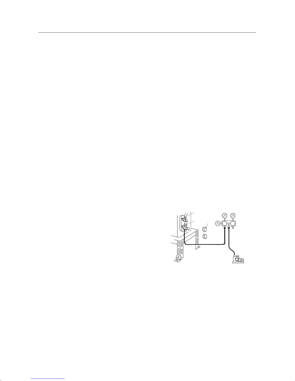
al muro
sopra
150 mm
Muro
Muro
Cablaggio elettrico delle unità interna ed esterna
1. Installare la dima dell’unità interna orizzintalmente
alla parete, e lasciare lo spazio necessario.
2. Se la parete è realizzata con mattoni o materiali simili, eseguire dei fori di 6 mm.
Inserire dei tasselli appropriati.
3. Fissare saldamente la dima al muro.
1. Aprire il pannello frontale verso l'alto.
2. Rimuovere il coperchio della scatola comp. elettrici.
Svitare le vite di fissaggio del coperchio scatola comp. elettrici per rimuoverlo.
3. Far attraversare il cavo di alimentazione tramite la parte posteriore del foro del cavo
dell'unità interna e tirarlo fuori.
4. Tutti i collegamenti dovrebbero essere connessi secondo lo schema circuito attaccato
sull'unità.
5. Avvolgere il cavo di alimentazione, che con la guaina nella scanalatura del cavo poi
chiudere il coperchio usando le vite di fissaggio, stringere il cavo di connessione.
6. Chiudere il pannello frontale.
7. Per le unità a pompa di calore, il cavo di controllo può essere passato attraverso il collegamento del connettore e dell'unità interna usando il clip del cavo che si trova sotto il corpo
19

Installazione dell’unità interna
NOTA:
Installazione unità interna
Installazione tubo collegamento
Diametro dado esagonale
Forzadi torzione (Nm)
Chiave
Coppia torcente
Tubazioni unità interna
Dado Tubazioni
Gancio fissazione
Fig.4
Piastra installazione
Piastra
installazione
Destra
Parte sinistra posteriore
Fig.3
Parte destra posteriore
Sinistra
Fig.2
Pedinament 3
Pedinament 2
Pedinament 1
Gas side piping
electric wire
Liquid side
piping
Tubo di scarico condensa
Coprire alla fine
con nastro
Isolamento tubazioni
lato liquido
Se il cavo di alimentazione non è abbastanza lungo per effetuare il collegamento, si prega di
contattare il negozio autorizzato per acquistare un cavo elettrico il cavo giusto abbastanza lungo.
Il collegamenti elettrico deve essere fatto correttamente, un collegamento errato può causare un
malfunzionamento dei pezzi di ricambio.
Stringere la vite della morsettiera per evitare allontamenti delle connessioni.
Un errato collegamento del cavo di messa a terra , può causare scossa elettrica.
Il coperchio della scatola comp. elettrici deve essere fissata bene. Stringe il cavo di collegamento, se è
stato mal connesso per evitare l’ingresso della polvere, l’umidità entro oppure la morsettiera sarà
influenzato dalle vibrazioni chè può causerà incendio o scossa elettrica.
L'interruttore di perdita e l'interruttore d'aria di capacità corretta devono essere installati.
Le tubazioni possono essere condutte fuori dalla destra, la
parte posteriore destra, sinistra o parte posteriore sinistra.
1. Nel istradamento delle tubazioni e di collegamenti dalla
sinistra o dalla parte destra dell'unità interna, tagliare i
pedinamenti dal basamento se necessario (Fig.2)
(1). Tagliare i pedinamenti 1 nel’istradamento soltanto dei
collegamenti;
(2). Tagliare i pedinamenti 1 e pedinamenti 2
nel’istradamento entrambi dei collegamenti e delle tubazioni
2. Tirare fuori le tubazioni dal corpo dell’unità, coprire le
tubazioni, cavo alimentazione stridente, tubo di scarico
condensa con nastro adesivo e farli passare attraverso il
foro tubazioni (vedere fig. 3)
3. Appendere le scanalature di montaggio dell'unità interna
sulle linguette superiori del pannello posteriore. (vedere
1. Allineare il centro delle tubazioni lucidi con la sua propria
valvola.
2. Fissare il dado lucido a mano e dopo stringere il dado
con una chiave e coppia torcente, riferirsi alla seguente.
tabella di coppia di torsione.
NOTA: In primo luogo connettere il tubo di collegamento all'unità interna, dopo all'unità
esterna; prestare attenzione alla piegatura delle tubazioni, non danneggiare il tubo di
collegamento; non stringere troppo il dado giuntura, altrimenti può causare la perdita.
6
9.52
12
16
19
15 - 20
31 - 35
50 - 55
60 - 65
70 - 75
20

Assicurarsi che i collegamenti fra unità interna ed
esterna vengano eseguiti rispettando le numerazioni
delle rispettive morsettiere.
E’ consigliata l’installazione di un dispositivo a corrente differenziale (RCD) che abbia una corente differenziale di funzionamento nominale che non superi i 30
mA.
Fissare saldamente l’unità con bulloni su un pavimento piano e resistente. Se si intende installare l’unità a
muro o sul tetto, assicurarsi di fissare saldamente il
supporto per evitare che si muova in seguito a intense vibrazioni o vento forte.
Non installare l’unità esterna in cave e/o bocche di
lupo
Installazione delle tubazioni
Utilizzare tubazioni di collegamento ed attrezzature
idonee al refrigerante presente nella macchina (vedi
targhetta caratteristica).
Le linee frigorifere non devono superare le lunghezze
massime riportate nella tabella dei dati tecnici.
Isolare termicamente tutte le linee frigorifere e le giunzioni.
Serrare le connessioni con il metodo “chiave contro
chiave”.
Installare l’attacco di scarico e il tubo flessibile di scarico
La condensa defluisce dall’unità esterna quando l’apparecchio opera in modalità riscaldamento. Per non disturbare i
vicini e rispettare l’ambiente, installare un attacco di scarico
e un tubo flessibile di scarico per canalizzare l’acqua di
condensa. È sufficiente installare l’attacco di scarico e la
rondella in gomma sullo chassis dell’unità esterna, quindi
connettervi un tubo flessibile di scarico come indicato in
figura.
Non installare l’unità esterna in luoghi dove l’irraggiamento solare colpisca direttamente l’apparecchio.
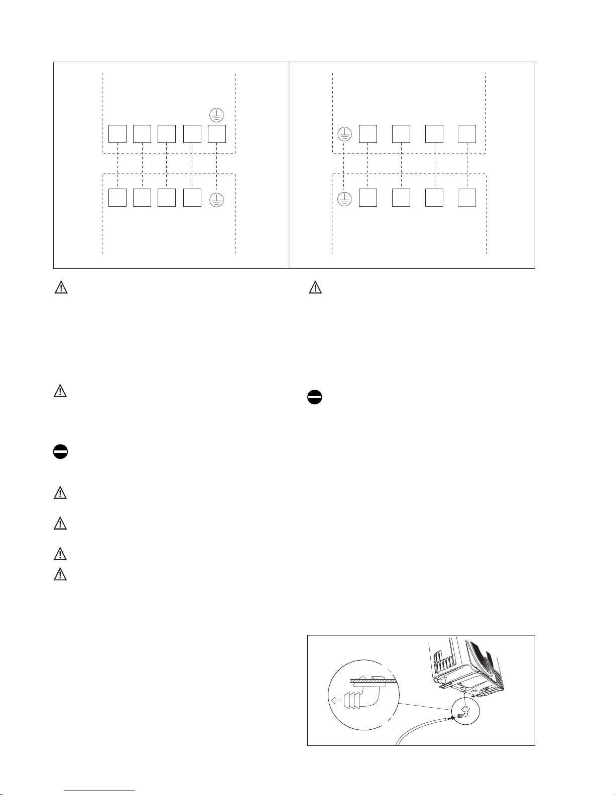
SCHEMI ELETTRICO DI COLLEGAMENTO
N 2 4 5
N(1) 2 4 5
4 5
4 5
N(1)
N(1)
2
2
UNITA’ INTERNA UNITA’ INTERNA
UNITA’ ESTERNA UNITA’ ESTERNA
9.000 btu/h e 12.000 btu/h 18.000 btu/h
21

Controlli dopo l’installazione
Eventi da controllare
Problemi connessi con l’errata installazione
L’installazione è corretta? L’unità potrebbe cadere, vibrare o fare rumore
Sono state controllate le perdite di gas? Raffrescamento o riscaldamento
insufficienti
L’isolamento termico dell’unità è
sufficiente?
Si potrebbe generare condensa e caduta di
goccie d’acqua
Il drenaggio dell’acqua è a posto?
Si potrebbe generare condensa e caduta di
goccie d’acqua
L’alimentazione è conforme a quanto
prescritto nelle specifiche dell’etichetta
tecnica?
Le linee di alimentazione e le tubazioni
sono installate correttamente?
L’unità è messa a terra correttamente? Rischio di dispersioni elettriche
Le linee sono in conformità a quanto
richiesto?
Le unità si potrebbero danneggiare o i
componenti si potrebbero bruciare
Ci sono ostacoli vicino all’ingresso o
uscita aria delle unità interne o esterna?
E’ stata memorizzata la lunghezza delle
tubazioni e la carica di refrigerante?
Non è semplice decidere la carica di gas
refrigerante. Rivolgersi all’installatore o
all’assistenza
Le unità si potrebbero danneggiare o i
componenti si potrebbero bruciare
Le unità si potrebbero danneggiare o i
componenti si potrebbero bruciare
Le unità si potrebbero danneggiare o i
componenti si potrebbero bruciare
22

ENGLISH
23
Please read the following carefully before operating
Notices for operation
When the voltage
is very high,
the components would be
easily damaged, when the
voltage is very low, the
compressor vibrates terribly
and that the refrigerant
system will be damaged, the
compressor and electric
components cannot work, the
voltage should be stable;
there shouldn’t be big
fluctuation.
Be sure to pull out the power
plug as the air conditioner not
in use for a long time.
Otherwise, the accumulated
dusts that may cause over
heating or fire.
Never splice the power cord or
use an extended cord.
It can cause overheating or
fire.
The power supply must adopt
the special circuit that with air
switch protection and assure
it has enough capacity.
The unit will be turned on or
off according to your
requirement automatically,
please do not turn on or turn
off the unit frequently,
otherwise disadvantage effect
may be caused to the unit.
Don’t leave windows
and doors
open for
a long time while
operating the air conditioner.It
can decrease the air
conditioning capacity.
Keep combustilble
spray away from the
units more than 1m.
Don’t attempt to repair
the air conditioner by
yourselfhe.
When having a burning smell or
smoke, please turn off the power
supply and contact with the
service center.
If the abnormity still exists,
the unit may be damaged,
and may cause electric shock
or fire.
It can cause a fire or explosion
Don't block the air
intake or
outlet vents
of both the outdoor
and indoor units.
It can decrease the air conditioning
capacity or cause a malfunction.
24
Notices for use
Swing louver
Please don't cut off or damage the
Guide louver
power cords If they are damaged,
please ask the qualified personnel
to change them.
Don’t insert your hands or stick into
the air intake or outlet vents.
Don’t apply the cold wind to the
body for a long time. It can cause
the health problems.
Splashing water on the air
conditioner can cause an electric
shock and malfunction
Don’t place a space heater
near the air conditioner
To adjust the airflow direction
appropriately. At operating,the
Don’t blow the wind to animals and
plants directly. It can cause air flow
direction
Don’t use the air conditioner for
other purposes, such as drying
clothes, preserving foods, etc.
louvers of air conditioner could be
adjusted by pressing the SWING button
on wireless
remote control to change the
airflow direction.
25
Notices for operation
Working principle and special functions for coo
Principle:
Anti-freezing function
Principle:
Defrosting:
The climate type of this unit is according to the nameplate.
Air conditioner absorbs heat in the room and transmit to outdoor and discharged, so that
indoor ambient temperature decreased, its cooling capacity will increase or decrease by
outdoor ambient temperature.
Air conditioner absorbs heat in the room and transmit to outdoor and discharged, will
increase, its heating capacity will decrease by outdoor ambient temperature. so that
indoor ambient temperature increased, so room heating capacity.
If outdoor temperature got lower, please operate with the other heating ventilating
equipments.
In "HEAT" mode, if in the following status, the indoor heat exchanger haven't achieve the
certain temperature, that the indoor unit will not act, in order to prevent cool air blowing.
(Within 3mins)
1.Heating starts. 2.Afer Auto defrosting finished. 3.Heating under the low temperature.
When outdoor temperature is low but high humidity, after a long while running, frost will
form on outdoor unit, that will effect the heating effect, at this time, the auto defrosting
function will act, the heat running will stop for 8-10mins.
During the auto defrosting, the fan motors of indoor unit and outdoor unit will stop.
During the defrosting, the indoor indicator flashes, the outdoor unit may emit vapor. This
is due the the defrosting, it isn not malfunction.
After defrosting finished,the heating will recover automatically.
If the unit is running in COOL mode and in low termperature, there will be frost formed on
the heat exchanger , when indoor heat exchanger temperature decreased below 0 the
indoor unit microcomputer will stop compressor running and protect the unit.
ling
Working principle and special functions for heating
26

Names and functions of each part
Indoor unit
Outdoor unit
Air in
Air out
(1) Manual switch
(2) Front panel
(5) Receiving window
(3) Filter
(4) Guide louver
(6) Bind tape
(7) Connection wire
(8) Drainage pipe
(9) Remote control
(1) Air outlet grille
(2) Valve
diagram of the appliance and may not correspond to the appearance of the units that have been purchased.
Air in
Air out
2
3
4
1
6
5
7
9
1
2
8
27
English
OPERATION AND DISPLAY
REMOTE CONTROL
The shape and position of switches and indicators may
vary according to the model, but their function is the
same.
Danger of electric shock with open grille.
If the remote control is lost, proceed as follows:
- When the unit is off, press the AUTOMATIC RESTART
key on the unit to turn the air conditioner on; the
conditioner will switch to cooling, drying or heating
mode depending on the conditions in the room in order
to provide the best comfort level.
- To turn off the unit, press the Automatic restart button
USER
Signal
receiver
Led Function
COOL COOL mode
HEAT HEAT mode
SET
Indicates the temperature in
°C
ON-OFF
Indicates when the unit is
working
DRY DRY mode
Button Function
ON/OFF On/Off button
MODE Selection of mode of operation
( - ) DOWN
Decreases the temperature and time by 1
unit
( + ) UP
Increase the temperature and time by 1
unit
FAN Selection of fan speed
SLEEP Night function
SWING To adjust the position of the flaps
TIMER Sets the TIMER
28

-
Replace the old batteries with new ones of the same
type when the display is no longer legible.
The remote control batteries must be disposed of in
accordance with the applicable laws in force in the
country of use.
How to use the remote control
To start the air conditioner, point the remote control at the
signal receiver. The remote control works up to a maximum
distance of 8 metres from the indoor unit.
Keep the remote control at a distance of at least 1 m
from the television or other electrical appliances.
Signal receiver
The remote control display remains active even when
the unit is not in operation.
Remote control DISPLAY
Meaning of symbols on the liquid crystal display
AUTO
COOL
DRY
Auto mode indicator
Cooling mode indicator
Drying mode indicator
FAN
Fan mode indicator
Heating mode indicator
Air flap ON indicator
Sleep mode indicator
Remote control lock indicator
Speed indicator: super min, min, med, max
Timer ON indicator
Timer OFF indicator
Degrees Fahrenheit set indicator
Degrees Celsius set indicator
Timer set indicator
HEAT
SWING
SLEEP
LOCK
SPEED
T-ON
T-OFF
°F
°C
.5H
Signal reception indicator
29
Mode of operation
ON/OFF
On/Off/Stand-by.
The symbol appears on the remote
control display when the conditioner is
switched on. When the unit is switched
off or on, the Timer and Sleep functions
are cancelled.
FAN
(Fan Mode)
Every time the FAN button is pressed
the speed changes in the following
sequence: AUTO - LOW – MEDIUM
– HIGH. If you select the AUTO FAN
speed, the electronic control chooses
the fan speed automatically.
SWING
Airflow adjustment. Press the “SWING”
button to start the automatic movement
of the airflow direction adjustment flaps;
press the “SWING” button again to stop
the flaps moving. If this function is started
in the HEAT mode, there will be a slight
delay to ensure an immediate output of
hot air in order to enjoy a comfortable
temperature immediately (Hot-Start
function).
MODE
Mode of operation selection. Every time
the MODE button is pressed the mode
of operation changes in the following
sequence: SMART - COOLING - DRY FAN - HEATING.
The default mode is AUTO.
TEMP
Down/Up
Setting of temperature. Press once to
SBJTFPSMPXFSUIFTFUUFNQFSBUVSF
by 1°C.
Available range of temperature settings:
- HEATING 16°C ~ 30°C
- COOLING 16°C ~ 30°C
- DEHUMIDIFYNG 16°C ~ 30°C
- FAN 16°C ~ 30°C
Do not turn the vertical airflow direction flaps by hand,
since this could cause malfunctioning. In the case of
flap malfunction, first of all switch off the appliance,
disconnect it from the power supply and then reconnect it.
Adjustment of horizontal airflow (manual)
Note: the unit shown here may be different from the air conditioner you have purchased.
This adjustment must be done with the appliance
switched off.
MODES OF OPERATION
Note: the appliance will start in the mode of operation that
was selected before switching off.
30

TIMER MODE
HEATING MODE
COOLING MODE
To activate heating mode (HEAT), press the MODE key until
the ( ) symbol comes up on the display next to the word
HEAT.
The appliance is fitted with a Hot Start function, which de-
lays appliance start-up for a few seconds to ensure an immediate output of hot air.
To activate cooling mode (COOL), press the MODE key until
the (
) symbol comes up on the display next to the word
COOL.
To change the temperature value, use the 61BOE
DOWN buttons. Each time the buttons are pressed the set
temperature value increases or decreases by 1°C.
Automatic switching-on
To set the automatic switching-on of the air conditioner, proceed as follows:
- With the unit switched off, press the TIMER key.
The ( ) symbol under T-ON and the letter H will blink for
5 seconds.
During this time:
Press DOWN keys.
Every time the keys are pressed, the value changes by
0.5h (from 0.5 to 24h).
If the setting is accepted, the display will show the set
value before switching back to showing the temperature.
Note: to cancel the function setting, press the TIMER ON
button again.
Automatic switching-off
To set the automatic switching-off time, proceed as follows:
- With the unit switched off, press the TIMER key.
The (
) symbol under T-OFF and the letter H will blink
for 5 seconds.
During this time:
Press DOWN keys.
Every time the keys are pressed, the value changes by
0.5h (from 0.5 to 24h).
If the setting is accepted, the display will show the set
value before switching back to showing the temperature.
Note: to cancel the function setting, press the TIMER OFF
button again.
31

English
DRY MODE
FAN MODE
Dehumidifying mode
To activate drying mode (DRY), press the MODE key until
the ( ) symbol comes up on the display next to the word
DRY.
The appliance activates according to the room and the set
temperature:
t*G UIF SPPN UFNQFSBUVSF JT ¡$ MPXFS UIBO UIF TFU
temperature, the compressor and the outdoor unit stop
while the indoor unit fan operates at low speed.
t*G UIF SPPN UFNQFSBUVSF JT ¡$ IJHIFS UIBO UIF TFU
temperature, the appliance automatically passes to the
dehumidifying function, activating the fan at low speed.
AUTO MODE
Room temperature Modr
Between 22°C HEATING
22 ~ 24°C DRY
Modalità automatica
Above 26°C COOLING
To activate AUTO (automatic) mode, press the MODE key
on the remote control until the ( ) symbol comes up on the
display next to the word AUTO.
In AUTO mode, fan speed, operating mode and temperature will all be set automatically to produce a comfortable
climate based on the ambient temperature.
While AUTO mode is active, the temperature is not shown
on the display.
Fan mode
To activate fan mode (FAN), press the MODE key until the
(
) symbol comes up on the display next to the word FAN.
Every time the FAN button is pressed the speed changes in
the following sequence: AUTO – LOW – MEDIUM – HIGH.
The remote control also stores the speed that was set in the
previous mode of operation.
In AUTO mode, the air conditioner automatically chooses the
fan speed and the mode of operation (COOLING or HEATING).
32
SLEEP MODE
Night mode
To activate sleep mode while the unit is in COOL, DRY or
HEAT mode, press the SLEEP key. ( ) will appear on the
display next to the word SLEEP.
To deactivate the night function, press the SLEEP button
again.
During operation in the night mode, the set temperature
increases by 1 °C in the first hour of operation and by
another 1 °C in the following hour, maintaining this increase
of 2°C in the subsequent hours.
Selecting the night function in the heating mode, the set
temperature decreases by 1 °C in the first hour of operation
and by another 1 °C in the following hour, maintaining this
decrease of 2°C in the subsequent hours with the fan operating at minimum speed.
Note: The SLEEP function is not available when in AUTO or
FAN mode.
AUXILIARY SWITCH
If the remote control is broken or malfunctioning, the unit
may be switched on and off using the auxiliary switch 1.
Switching on
- With the unit switched off, press the auxiliary switch and
the air conditioner will start up in AUTO mode
Switching off
- With the unit switched on, press the auxiliary switch and
the air conditioner will switch off.
1
33

Clean and care
CAUTION
)
Turn power off and pull out the power plug before cleaning air conditioner. Or it may
cause electric shock.
Never sprinkle water on the indoor unitf or cleaning because it can cause an electric
shock.
Volatile liquid (e.g. thinner or gasoline) will damage the air conditioner. (So wipe the
units with a dry soft cloth, or a cloth slightly moistened with water or cleanser.)
-1- Take off the front panel
Along the direction of arrows to lift the
front panel up, mean while to hold b oth
slots of the front panel and take it out
forcibly and then can take it off.
-2- Washing
Clean w ith a softbrush, water and neutral detergent, and then to dry it. (Note:
Never use the water above 45°C to
wash the panel, or it could cause
defor-
mationor discolouration.)
-3- In
stall front panel
Place two s upporters of the front panel
into the slots, along the direction of
arrows to cover and claspthe front panel.
Asshow in righ figure.
Note: If dust is much more around the air conditioner, the air filters should be cleaned manytimes. After takingoff the filter,don't touchthe finof indoorunit, inorder toavoid hurtyourfingers.
Cleaningtheairfilters (Recommendedonceeverythreemonths
Clean the front panel( make sureto take it off before clea ning)
34

Check before use
Maintain after use
D
E
Clean and care
-1- Take down the air filter
At the slot of surface panel to open an angle, pull theair filter
downward and take it out.
-2- Cleaning
To clean the dust adhering to the filters, you can eitheruse a
vacuum cleaner, or wash them with warm water (the water
with the neutral detergent should below 45 C). When the
filters are very dirty (such as oil stain), and dry it in the shade.
NOTE: Never use water above 45° to wash, or it cancause
deformation or discoloration. Never partch it byfire, or can
cause a fire or deformation.
-3- Reinsert the filters
Reinsert the filters along with the arrow head, then coverthe
surface panel and clasp it.
-1- Be sure that nothing obstructs the air outlet and intake vents.
- 2- Check that whether ground wire is properly connected or not.
-3- Check that whether the batties of air conditionearechanged or
not.
-4- Check that whether the installation stand of the otdoorunit is damaged or not. If damaged, please contact the dealer.
-1- Turn main power off.
-2- Clean the filter and indoor and outdoor units' bodies.
-3- Repaint the rubiginous place on the outdoor unit to prevent it from spreading.
35

Troubleshooting
Warning
Phenomenon
Troubleshooting
waiting
Do not repair the air conditioner at your discretion. Incorrect repair may cause electric
Authorized Service Center for professional repair.
Following checks prior to contact may save your time and costs.
The unit can not operte immediately
when the air conditioner is restarted.
There's unusual smell blowing from the
outlet after operation is started.
Sound of water flow can be heard
during operation.
This is caused by the odors into the
room which have been breathed in to
the air conditioner.
This is caused by the refrigerantflowing inside the unit.
Because the air of the room is
cooled down rapidly by the cold wind
and it looks like the fog.
Mist is emitted during cooling operation.
Once the air conditioner is stopped,
it will not operate in approximately 3
minutes to protect itself.
36
Troubleshooting
Break off
Phenomenon
Troubleshooting
Wireless Remote control is not
available.
Creaking noise can be heard when
start or stop the unit.
This is caused by the deformation of
plastic due to the change of temperature.
Air conditioner does not operateat all.
- Has the power been shut down?
- Is the wiring loose?
- Is the leakage protection switch in
operation?
- Is voltage higher or lower?
- Is TIMER ON in operation?
- Is SET TEMP. suitable?
- Is air inlet or outlet obstructed?
- Are air filters dirty?
- Are the windows and door closed?
- Is indoor fan speed set at low speed?
- Is there any other heat source in your
room?
- Remote control can'tbeused occasionally
when the air conditioner is disturbed or
changing its functions frequently. At that
time, pull out the power plug and insert it
again to recover the operation.
- Is the remote control out of effective
disance to the indoor unit?
- Are there any obstruction between the
remote control and the signal receptor?
Replace the worn batteries of remote
control if the voltage of the batteries is
not sufficient.
Cooling (Heating) efficiency is not goo
37
Troubleshooting
Phenomenon
Troubleshooting
Immediately stop all operations and plug out, contact
Indoor unit cannot deliver air In HEAT mode, when the temperature of
the dealer in following situations.
indoor heat exchanger is very low, that will
stop deliver air in order to prevent coolair.
(Within 3min)
In HEAT mode, when the outdoor temperature is low or high humidity, there are much
frost be formed on the outdoor heat
exchanger, that the unit will automatically
defrost, indoor unit stop blowing air for 810min.During the defrosting,there is water
flowing out or vapor be produced.
In dehumidifying mode, sometimes fan will
stop, in order to avoid condensing water be
vaporized again, restrain temperature rising.
- The air humidity is on the high side.
- Condensing water overflowed.
- The connection position of indoor unit
drainage pipe is loosed.
- The sound of fan or compressor relay is
switching on or off.
- When the defrosting is started or stop
running, it will sound. That is due to the
refrigerant flowed
If unit is running under the high humidity fora
long time, the moisture will be condensedon
the air outlet grill and drip off.
Noise from indoor unit emitted.
Noise from indoor unit emitted.
If water leakage in the room
Moisture on air outlet vent
There is harsh sound during operation
The terrible odors emitted during operation
Water is leaking in the room
Air switch or protection switch often breaks
Carelessy splash water or something into unit
There is an abnormal heat in power supply cord
Stop running and pull out of the plug.
and power plug.
38

INSTALLATION
39

Installation service- Notices for installation
Important Notices
Basic Requirements For Installation Position
Indoor Unit Installation Position Selection
1. The unit installation work must be done by qualified personnel according to the local
rules and this manual.
2. If the air conditioner has not plug, directly connect it into the fixed circuit, a breaker should
be installed in the fixed circuit. all pole of this breaker should be switching off and the
distance of the contact should be at least 3mm.
Install in the following place may cause malfunction. If it is unavoidable contact with
service center please:
- Place where strong heat sources, vapors, flammable gas or volatile objuct are emitted.
- Place where high-frequency waves are generated by radio equipment, welders and
medical equipment.
- Place where a lot of salinities such as coast exists.
- Place where the oil (machine oil) is contained in the air.
- Place where a sulfured gas such as the hot spring zones is generated.
1. The air inlet and outlet vent should be far from the obstruction, make sure that the air
can be blown through the whole room.
2. Select a position where the condensing water can be easily drained out, and the place
is easily connected for outdoor unit.
3. Select a location where the children can not reach.
4. Can select the place where is strong enough to withstand the full weight and vibration
of the unit. And will not increase the noise.
5. Be sure to leave enough space to allow access for routine maintenance. The height of
the installed location should be 230 cm or more from the floor.
6. Select a place about 1m or more away from TVset or any other electric appliances.
7. Select a place where the filter can be easily taken out.
8. Make sure that the indoor unit installation should accord with installation dimension
40

Installation service- Notices for installation
Important Notices
Basic Requirements For Installation Position
Indoor Unit Installation Position Selection
1. The unit installation work must be done by qualified personnel according to the local
rules and this manual.
2. If the air conditioner has not plug, directly connect it into the fixed circuit, a breaker should
be installed in the fixed circuit. all pole of this breaker should be switching off and the
distance of the contact should be at least 3mm.
Install in the following place may cause malfunction. If it is unavoidable contact with
service center please:
- Place where strong heat sources, vapors, flammable gas or volatile objuct are emitted.
- Place where high-frequency waves are generated by radio equipment, welders and
medical equipment.
- Place where a lot of salinities such as coast exists.
- Place where the oil (machine oil) is contained in the air.
- Place where a sulfured gas such as the hot spring zones is generated.
1. The air inlet and outlet vent should be far from the obstruction, make sure that the air
can be blown through the whole room.
2. Select a position where the condensing water can be easily drained out, and the place
is easily connected for outdoor unit.
3. Select a location where the children can not reach.
4. Can select the place where is strong enough to withstand the full weight and vibration
of the unit. And will not increase the noise.
5. Be sure to leave enough space to allow access for routine maintenance. The height of
the installed location should be 230 cm or more from the floor.
6. Select a place about 1m or more away from TVset or any other electric appliances.
7. Select a place where the filter can be easily taken out.
8. Make sure that the indoor unit installation should accord with installation dimension
41
Installation dimension diagram
Indoor unit Installation dimension diagram
Space to the ceiling
Space to the wall
Space to the wall
Space to the floor
Air outlet side
Installation dimension diagram
Space to the wall
Space to the obstruction
Air outlet side
Air inlet side
( > 300 cm )
( > 15 cm )
( > 230 cm )
( > 15 cm )
( > 15 cm )
( > 30 cm )
( > 50 cm )
( > 200 cm )
( > 50 cm )
( > 30 cm )
42

Indoor unit installation
Install the rear panel
Install the piping hole
Install the water drainage pipe
Wrenched
Bent
Outdoor
Indoor
Flooded
Wall pipe
Seal pad
Fig.1
(Rear piping hole)
(Rear piping hole)
Left
Right
Mark on the middle of it
Gradienter
Space to
the wall
150mm
above
Space to
the wall
150mm
above
Wall
1. Always mount the rear panel horizontally. As the water drainage
Wall
Connect indoor and outdoor electric wires
kèlhling pipe at the left, when adjusting the rear panel, this side should not be too high; the
right side should be slightly high.
2. Fix the rear panel on the selected location
3. Be sure that the rear panel has been
fixed firmly enough to with stand the
weight of an adult of 60 kg, furthermore,
the weight should be evently shared by
each screw.
1. Make the piping hole in the wall at a slight downward slant to the
outdoor side.
2. Insert the piping-hole sleeve into the hole to prevent the connection
piping and wiring from being damaged when passing through the hole.
1. For well draining, the drain hose should be placed at a
downward slant.
2. Do not wrench or bend the drain hose or flood its end by
water. 3. When the long drainage hose passing through
indoor, should wrap the insulation materials.
1. Open the front panel upwardly.
2. Screw off the fixing screw of cover plate and screw off cover plate.
3. Put the power connection cable through the back of indoor unit wire hole and
take it out.
4. All the wiring should be connected according to the circuit diagram on the unit.
5. Put the power connection cable the section, which with sheath into wire groove,
and cover the cover plate, screw on the fixing screw, tighten the connection wire.
6. Cover the front panel cover.
7. For the cooling and heating unit, signal control wire can be passed through the
connection of connector and indoor unit, and use the wire clip that is under the
body case, tighten the signal control wire.
43

6
9.52
12
31 - 35
15 - 20
50 - 55
16
60 - 65
19
70 - 75
ƽ
Indoor unit installation
NOTE:
Install the indoor unit
Install the connection pipe
Hex nut diameter
Tightningtorque (Nm)
Spanner
Torque wrench
Indoor unit piping
Taper nut Piping
Fixing hook
Fig.4
Mounting
board
Mounting
board
Left
Right
Left rear
Fig.3
Right rear
Tailing 3
Fig.2
Tailing 2
Tailing1
Gas side piping
External connection
electric wire
Liquid side
piping
Liquid side
piping
insulation
Water drainage pipe
Finally wrap it
with tape
Gas side piping
insulation
When connecting the electric wire if the wire length is not enough, please contact
withthe authorized service shop to buy a exclusive electric wire that is long enough
and thejoint on the wire are not allowed.
The electric wiring must be correctly connected, wrong connection may cause spareparts
malfunction.
Tighten the terminal screw in order to prevent loose.
After tighten the screw, slightly pull the wire and confirm whether is it firm or not.If the
earth wire is wrong connection, that may cause electric shock.
The cover plate must be fixed, and tighten the connection wire, if it is poor installed,
thatthe dust, moisture may enter in or the connection terminal will be affected by outside
force,and will cause fire or elelctric shock.
Leakage circuit-breaker and air switch of correct capacity must be installed.
The piping can be lead out from right, right rear,left,
left rear.
When routing the piping and wiring from the leftor
right side of indoor unit, cut off the tailingsfrom the
chassis in necessary (show in Fig.2)
(1).Cut off the tailings 1 when routing the wiring only;
(2).Cut off the tailings 1 and tailings 2 when routingboth the wiring and piping.
Take out the piping from body case, wrap the
pipingelectric wire, water pipe with tape and put them
th-rough the piping hole (As show in Fig. 3)
3. Hang the mounting slots of the indoor unit on theupper tabs of the rear panel and check if it is firmenough.
(As show in Fig.4)
Align the center of the piping flare with the relevant
valve.
Screw in the flare nut by hand and then tightenthe nut
with spanner and torque wrench referto the following.
Tightening torque table
NOTE: Firstly connect the connection pipe to indoor unit, then to outdoor unit; pay atten-
tionto the piping bending, do not damage the connection pipe; the joint nut couldn't tighten
toomuch, otherwise it may cause leakage.
44
Air purgin g and l eakage t est
Electric Wiring
1. Disassemble handle of right side plate or front side plate of outdoor unit.
4. Ensure if wire has been fixed well.
5. Install handle or front side plate.
NOTE:
Wrong wiring may cause
spare parts malfunction.
After the cable fixed, make sure
there should be a free space
between the connection and
fixing place on the lead wire.
2. Take off wire clamp, connect and fix power connect cord to terminal of line bank.
Wiring should fit that of indoor
unit.
3. Fix the power connection cable with wire clamp, for cooling and heating unit, then use the
wire clamp to fix the signal control wire, then connect the corresponding connector.
Air purging and leakage test
Liquid pipe
Gas pipe
Valve
cap
Vacuum
gauge
Vacuum pump
1. Connect charging hose of manifold valve to charge end of low
pressure valve (both high/low pressure valves must be tightly
shut).
2. Connect joint of charging hose to vacuum pump.
3. Fully open handle handle of Lo manifold valve.
4. Open the vacuum pump to evacuate. At the beginning, slightly
loosen joint nut of low pressure valve to check if there
is air coming inside.
5. After finishing evacuation, shut Lo handle of manifold
valve to stop the vacuum pump. (Keep evacuating for
more than 15 minutes and make sure the reading of
multi-meter is
6. Fully open high/low pressure valves.
7. Remove charging hose from charging end of low
pressure valve.
8. Tighten bonnet of low-pressure valve. (As shown in Fig.5)
Outdoor unit installation
45
Ensure that when connecting the indoor and outdoor
units, the numbering on the respective terminal blocks
is observed.
We suggest the installation of RCD device with nominal differential current that doesn’t exceed the 30 mA.
INSTALLING THE OUTDOOR UNIT
Location
Use bolts to secure the unit to a flat, solid floor. When
mounting the unit on a wall or the roof, make sure the
support is firmly secured so that it cannot move in the
event of intense vibrations or a strong wind.
Do not install the outdoor unit in pits or air vents
Installing the pipes
Use suitable connecting pipes and equipment for the
refrigerant in the appliance (see rating plate).
The refrigerant pipes must not exceed the maximum
lengths given in the technical data table.
Lag all the refrigerant pipes and joints.
Tighten the connections using two wrenches working
in opposite directions.
Install the drain fitting and the drain hose
Condensation is produced and flows from the outdoor unit
when the appliance is operating in the heating mode. In
order not to disturb neighbours and to respect the environment, install a drain fitting and a drain hose to channel the
condensate water. Install the drain fitting and rubber washer
on the outdoor unit chassis and connect a drain hose to it
as shown in the figure.
Do not install the outdoor unit where it is exposed to
sunlight.
N 2 4 5
N(1) 2 4 5
4 5
4 5
N(1)
N(1)
2
2
INDOOR UNIT INDOOR UNIT
OUTDOOR UNIT OUTDOOR UNIT
9.000 btu/h e 12.000 btu/h
18.000 btu/h
46
Check after installation and test operation
Items to be checked
Possible malfunction
The unit may drop, shake or emit noise.
Has it been fixed firmly?
It may cause insufficient cooling(heating)
Have you done the refrigerant leakage test?
capacity.
Is heat insulation sufficient?
It may cause condensation and dripping.
Is water drainage well?
It may cause condensation and dripping.
Is the voltage in accordance with the rated
voltage marked on the nameplate?
It may cause electric malfunction
or damage the part. .
Is the electric wiring and piping
It may cause electric malfunction
connection installed correctly and securely?
or damage the part.
Has the unit been connected to a secure
earth connection?
It may cause electrical leakage.
Is the power cord specified?
It may cause electric malfunction
or damage the part
Is the inlet and outlet been covered?
It may cause insufficient cooling(heating)
capacity.
Has the length of connection pipes
and refrigerant capacity been recorded?
47

TEKNO POINT
www.teknopoint.com
tecnico@teknopoint.com
klima@teknopoint.com
 Loading...