

Page 1
Page 2
Introduction
Disclaimer: Tekno RC is not responsible or liable for any property or personal damage, loss, or
injury incurred as a result of using this product. This kit is meant for use by persons 14 years of
age or older and in the strict connes of a legally permitted RC track or facility.
Warnings: Always double-check that your radio gear is working properly before operating vehicle.
Never operate the vehicle indoors (unless the RC track is an indoor facility). Use caution while
operating vehicle so as not to collide with people who may be turn marshalling or who might
otherwise not be aware that a fast moving RC vehicle is in the vicinity.
Warranty: We warrant that the parts included in this kit are free from defects. If you nd a
defective part in your kit, please contact us @ [email protected] and we will help you to resolve
the issue. We do not warranty parts that may be broken during operation of the vehicle or
otherwise. Refer to the end of this instruction manual for a listing of spare/replacement and
option parts. All spare parts and other info are available on our website (www.teknorc.com)
and through our network of domestic and international dealers and distributors.
Additional equipment and parts needed:
2/3 channel surface radio transmitter and receiver
High torque steering and brake servo (at least 300 oz/in)
RX battery, switch harness
.21 nitro engine, tuned pipe, manifold, and glow plug
Fuel bottle, fuel, 1/8th buggy starter box, and glow ignitor
1/8th scale buggy tires, wheels & CA glue
Paint for body
Tools needed:
Hex drivers 1.5mm (TKR1104), 2.0mm (TKR1105), 2.5mm (TKR1106)
Nut drivers 5.0mm (TKR1107, 5.5mm (TKR1108), 7.0mm (TKR1109)
17mm Wheel Wrench (TKR1116)
Hobby knife
Needle-nose pliers
Pivot Ball and Shock Multi-tool (TKR1115, for shock assembly)
4mm turnbuckle wrench (TKR1103)
4mm arm reamer
Lexan Body Scissors
Thank you for purchasing the Tekno RC NB48.3 1/8th 4WD Nitro Competition Buggy. The NB48.3
represents the state-of-the-art in 1/8th nitro buggy technology. We hope you have as much fun
driving your new vehicle as we did developing it. We are always working on new projects, so please
check our website (www.teknorc.com) regularly for the latest news, parts, and kits. Thanks again.
Page 3
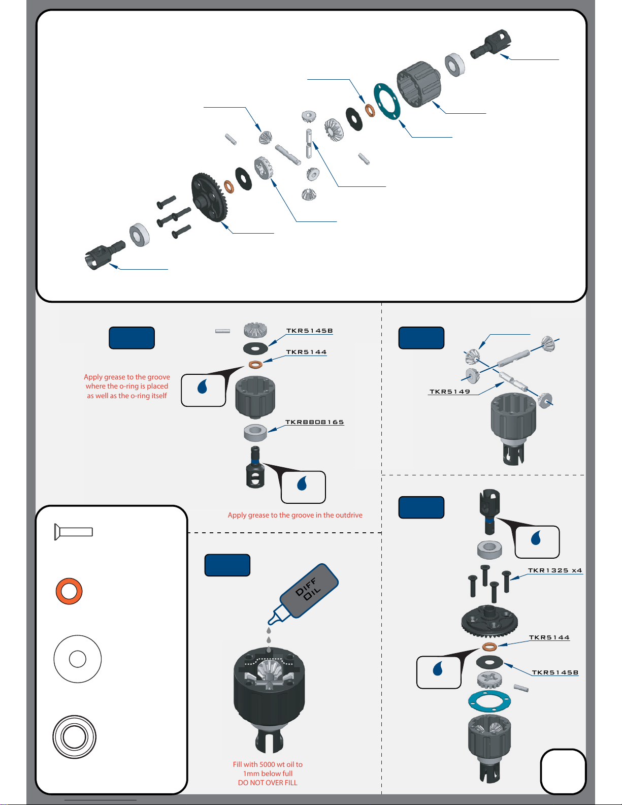
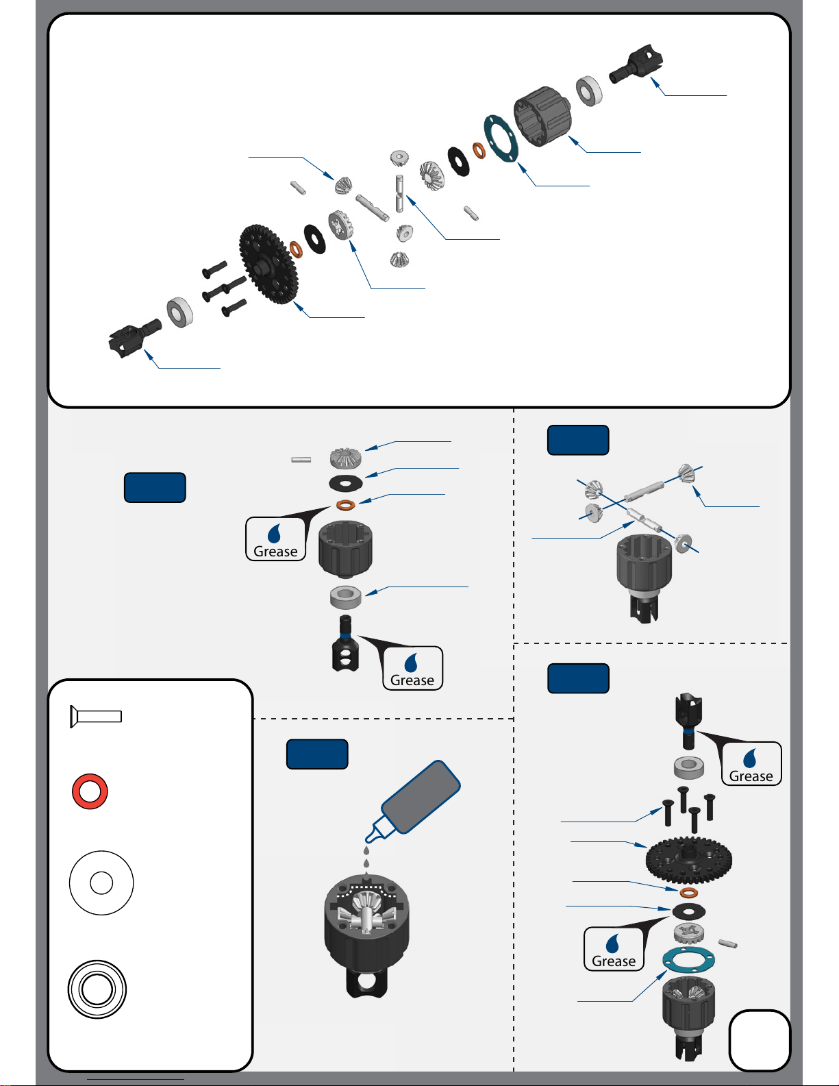
Apply grease to the groove
where the o-ring is placed
as well as the o-ring itself
Apply grease to the groove in the outdrive
Fill with 5000 wt oil to
1mm below full
DO NOT OVER FILL
TKR5145B
TKR5144
Bag A
Front Differential
(overview)
TKR5151
TKR5149
TKR5150
TKR5150
TKR5143
TKR5113
TKR1325
M3x14mm Flat Head Screw
x4
TKR5144
TKR5145B
TKRBB08165
Ball Bearing(8x16x5mm)
x2
TKR5144
Differential 0-rings
x2
TKR5145B
Differential Shims (6x17mm)
x2
TKR1325 x4
TKR5149
TKRBB08165
Diff
Oil
TKR5114X
TKR5114X
TKR5150
TKR5144
3
Grease
Grease
Grease
Grease
Step
A-2
Step
A-1
Step
A-4
Step
A-3
*TKR5149A
(Option)
*TKR5149A
(Option)
Apply a liberal
amount of grease in the
areas between the shims
and o-rings, as well as
around the outdrive and
both sides of the seal
Page 4
TKR1325
M3x14mm Flat Head Screw
x4
TKRBB08165
Ball Bearing(8x16x5mm)
x2
TKR5144
Differential 0-rings
x2
TKR5145B
Differential Shims (6x17mm)
x2
TKR5112X
TKR5112X
TKR5113
TKR5119
TKR5143
TKR5149
TKR5150
TKR5150
Grease
Grease
Grease
Grease
Bag B
Center Differential
(overview)
Step
B-1
Step
B-3
Step
B-4
Step
B-2
Diff
Oil
4
TKRBB08165
TKR5119
TKR5145B
TKR1325 x4
TKR5144
TKR5143
TKR5150
TKR5144
TKR5145B
TKR5150
Apply a liberal
amount of grease in the
areas between the shims
and o-rings, as well as
around the outdrive and
both sides of the seal
Apply grease to the groove
where the o-ring is placed
as well as the o-ring itself
Apply grease to the groove in the outdrive
Fill with 5000 wt oil to
1mm below full
DO NOT OVER FILL
TKR5149
*TKR5149A
(Option)
*TKR5115
(Option)
*TKR5115
(Option)
*TKR5149A
(Option)
Page 5

TKR1325
M3x14mm Flat Head Screw
x4
TKRBB08165
Ball Bearing(8x16x5mm)
x2
TKR5144
Differential 0-rings
x2
TKR5145B
Differential Shims (6x17mm)
x2
TKR5114X
TKR5114X
TKR5113
TKR5302
TKR5143
TKR5149
TKR5150
TKR5150
Grease
Grease
Grease
Grease
Apply grease to the groove
where the o-ring is placed
as well as the o-ring itself
Apply grease to the groove in the outdrive
Fill with 5000 wt oil to
1mm below full
DO NOT OVER FILL
*TKR5149A
(Option)
TKR5149
*TKR5149A
(Option)
Bag C
Rear Differential
(overview)
Step
C-1
Step
C-3
Step
C-4
Step
C-2
Diff
Oil
5
TKRBB08165
TKR5302
TKR5145B
TKR1325 x4
TKR5144
TKR5143
TKR5150
TKR5144
TKR5145B
TKR5150
Apply a liberal
amount of grease in the
areas between the shims
and o-rings, as well as
around the outdrive and
both sides of the seal
Page 6
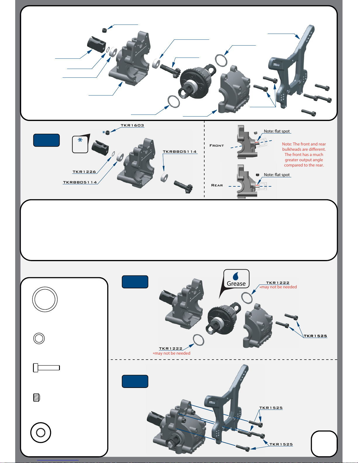
TKR5075
TKR5012
TKR5152
TKR5012
TKR5268
TKR1222
TKR1222
TKR1525
TKR1525
TKR1222
TKR1525
TKR1222
TKR1226
TKRBB05114
TKR1525
M3x14mm Cap Head Screw
x6
TKR1603
M5x4mm Set Screw
x1
TKR1222
13x16x0.1mm Diff Shim
x2
TKR1226
5x7x0.2mm Shim
x1
TKR1603
TKRBB05114
TKRBB05114
TKR1226
TKRBB05114
TKR1603
TKR1525TKR1525
Grease
Front
Rear
Note: at spot
Note: at spot
Note: The front and rear
bulkheads are dierent.
The front has a much
greater output angle
compared to the rear.
*
may not be needed
*
may not be needed
Bag D
Front Gearbox
(overview)
6
Thread
Lock
Step
D-1
Step
D-2
Step
D-3
Note: TKR1222 and TKR1226 Shims - The gear mesh should be tight without any binding. TKR1226 should
always be installed. Then test tment of the di with both TKR1222 shims on the gear-side of the di. If the di
turns freely without binding, continue to next step. If the di binds and does not turn freely (it will make a
grinding or crunching sound when spun), remove one TKR1222 shim from the gear side and install it onto the
other side of the di. Reassemble and test the mesh again. If it is still binding, remove the second TKR1222 shim
from the gear side and install it onto the other side of the di. When you are satised that you have the best
gear mesh possible continue to the next step. You may end up using only one shim on the gear side.
TKRBB05114
Ball Bearing (5x11x4)
x2
Page 7
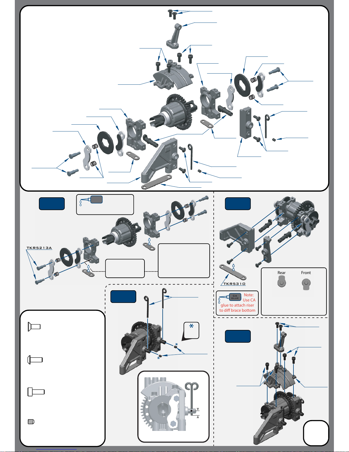
TKR5213A
TKR5213A
TKR1522
TKR5310
TKR5368
TKR5345B
TKR1522
TKR5213A
TKR5314B
TKR1601
TKR1601
TKR5310
TKR5336B
TKR5362
TKR5310
TKR5368
TKR5336B
TKR5345B
TKR5310
TKR1402
TKR5338
TKR1402
TKR5368
TKR5314B
TKR5314B
TKR5310
TKR5310
CA
glue
Note:
Use CA
glue to attach riser
to di brace bottom
TKR5310
Rear Front
Bag E
Center Differential Assembly
(overview)
Step
E-1
Step
E-3
Step
E-4
Step
E-2
7
TKR1522
TKR5310
TKR1322
TKR1522
TKR5215B
TKR5336B
TKR1601
TKR5346
TKR1322
Pre-thread all brake
post holes with a
separate M3 screw
Note: Tighten brake posts
(TKR5213A) all the way
down and then back o
1 FULL TURN. This will
ensure your brake discs
are free while on throttle.
Note: Orientation of the brake
cams TKR5215B. The rear cam
should be pointing up & the front
cam should be pointing down.
TKR1322
M3x8mm Flat Head Screw
X2
TKR1402
M3x8mm Button Head Screw
x4
TKR1522
M3x8mm Cap Head Screw
x4
TKR1601
M3x4mm Set Screw
x2
Thread
Lock
Note: Brake lever alignment
4mm
CA
glue
Note: Use CA
glue to attach
risers to di support bottoms
Page 8
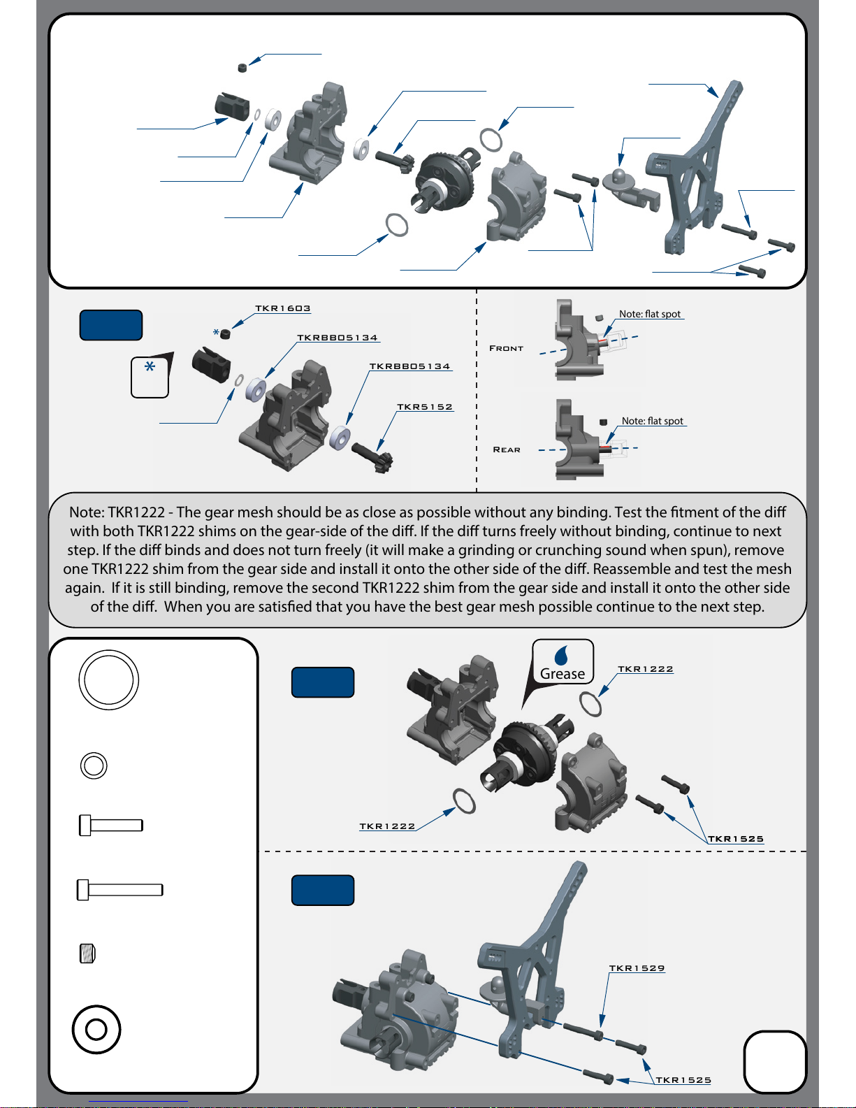
TKR5075
TKR5316
TKR5316
TKR5181
TKR5269
TKR1222
TKR1222
TKR1525
TKR1529
TKR1222
TKR1529
TKR1525
M3x14mm Cap Head Screw
x4
TKRBB05134
Ball Bearing (5x13x4)
x2
TKR1529
M3x20mm Cap Head Screw
x1
TKR1222
13x16x0.1mm Diff Shim
x2
TKRBB05134
TKRBB05134
TKR5152
TKRBB05134
TKR1603
TKR1603
TKR1525TKR1525
Grease
Front
Note: at spot
Note: TKR1222 - The gear mesh should be as close as possible without any binding. Test the tment of the di
with both TKR1222 shims on the gear-side of the di. If the di turns freely without binding, continue to next
step. If the di binds and does not turn freely (it will make a grinding or crunching sound when spun), remove
one TKR1222 shim from the gear side and install it onto the other side of the di. Reassemble and test the mesh
again. If it is still binding, remove the second TKR1222 shim from the gear side and install it onto the other side
of the di. When you are satised that you have the best gear mesh possible continue to the next step.
Rear
Note: at spot
TKR1525
TKR1525
TKR1222
TKR1226
TKRBB05134
TKR1603
M5x4mm Set Screw
x1
TKR1226
5x7x0.2mm shim
x1
Bag F
Rear Gearbox
(overview)
8
Step
F-1
Step
F-2
Step
F-3
Thread
Lock
Note: The front and rear of
the car use dierent inner
bulkheads.
The front is angled
whereas the rear is oset
and only slightly angled.
TKR5152
TKR1226
Page 9
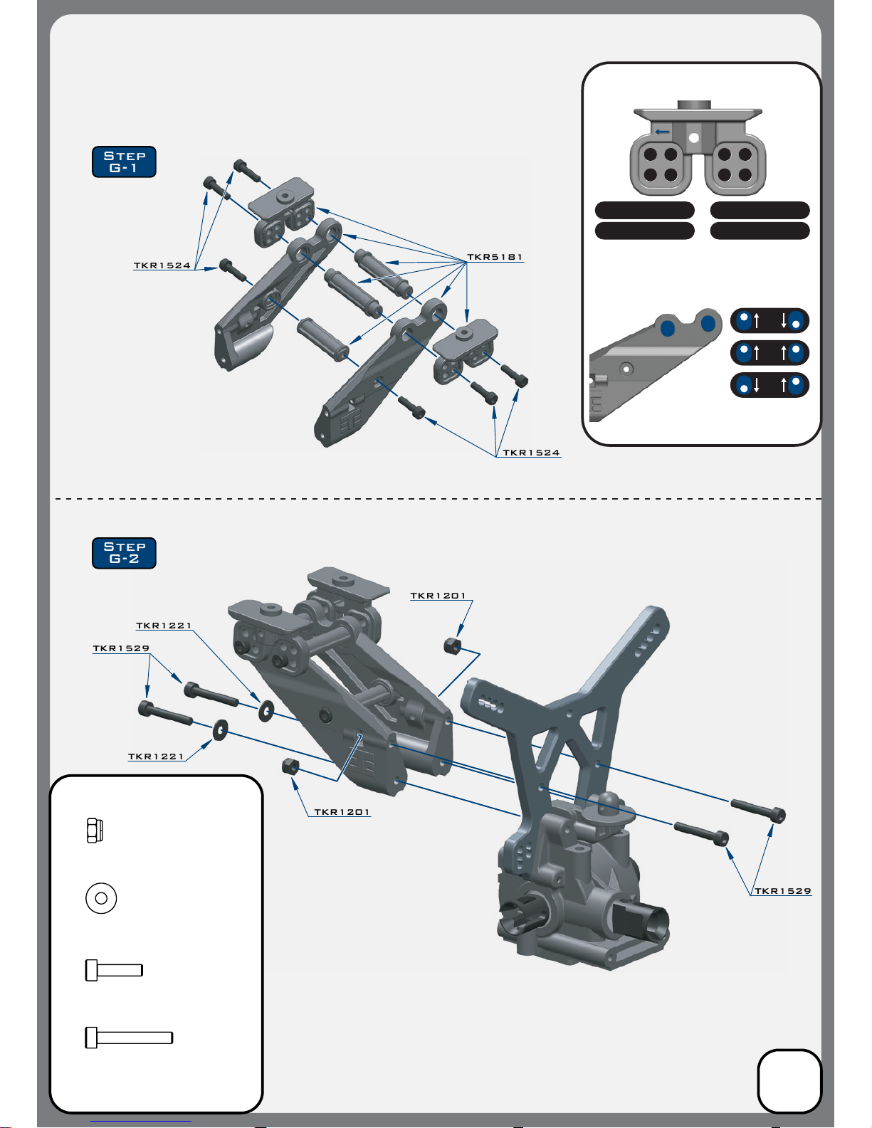
TKR1529
TKR1201
TKR1221
TKR1221
TKR1201
TKR1529
TKR1529
M3x20mm Cap Head Screw
x4
TKR1524
M3x12mm Cap Head Screw
x6
TKR1201
M3 Lock Nut Black
x2
TKR1221
M3x8mm Washer
x2
Step
G-1
Step
G-2
TKR1524
TKR1524
TKR5181
Bag G
Low Profile Wing Mount
9
SETTINGS
1 2
3 4
1 2
3 4
POSITION SETTINGS
1 - REARWARD LOW 2 - FORWARD LOW
3 - REARWARD HIGH 4 - FORWARD HIGH
DOWNFORCE SETTINGS
(downforce angles)
Note: Stock position setting is
# 4, Forward High
Note: Stock downforce setting is 4
°
4
°
7
°
10
°
Page 10
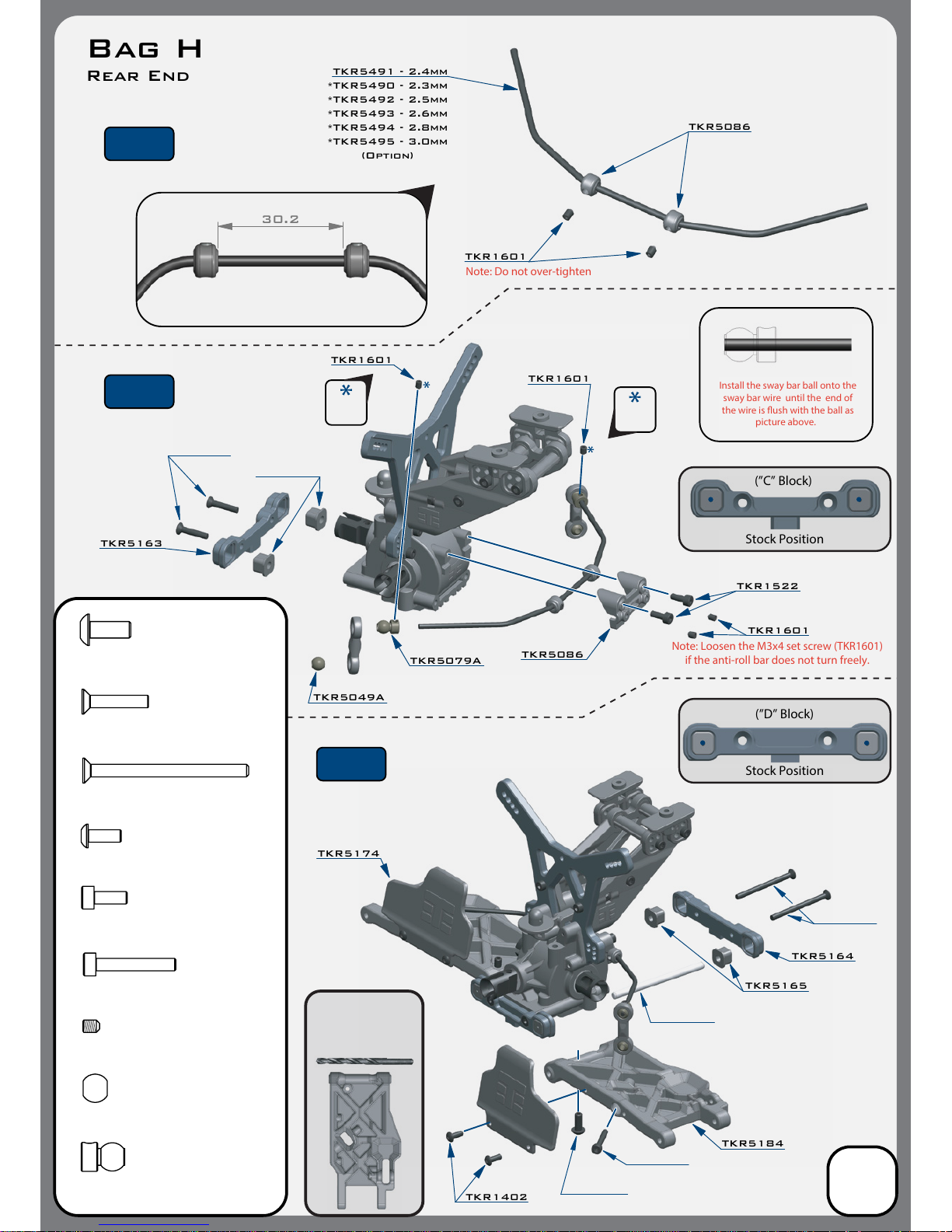
Stock Position
(”D” Block)
Stock Position
(”C” Block)
30.2
TKR1601
TKR1601
TKR1601
TKR5086
TKR5491 - 2.4mm
TKR5086
Install the sway bar ball onto the
sway bar wire until the end of
the wire is ush with the ball as
picture above.
Note: Loosen the M3x4 set screw (TKR1601)
if
the anti-roll bar does not
turn freely.
Note: Do not over-tighten
TKR5049A
TKR5163
TKR5164
TKR5165
TKR5184
TKR5174
TKR1402
TKR1601
TKR5079A
TKR1522
TKR1522
M3x8mm Cap Head Screw
x2
Bag H
Rear End
*TKR5490 - 2.3mm
*TKR5492 - 2.5mm
*TKR5493 - 2.6mm
*TKR5494 - 2.8mm
*TKR5495 - 3.0mm
(Option)
Thread
Lock
Thread
Lock
10
TKR1327
TKR1333
M3x40mm Flat Head Screw
x2
TKR1238
M4x10mm Droop Screw
x2
TKR5049A
Pivot Ball Sway Bar
x2
TKR5079A
Stabilizer Ball
x2
TKR1529
M3x20mm Cap Head Screw
x2
TKR1327
M3x16mm Flat Head Screw
x2
TKR1333TKR1333
TKR1238
TKR1529
TKR1601
M3x4mm Set Screw
x6
Step
H-1
Step
H-2
Step
H-3
TKR5020
TKR1402
M3x8mm Button Head Screw
x4
TKR5165
Note: With these stock
center dot settings,
Anti-Squat = 2° / Rear Toe = 3°
Use a #19 drill bit or
4mm reamer to ream
arms until hinge pin
falls through freely.
Page 11
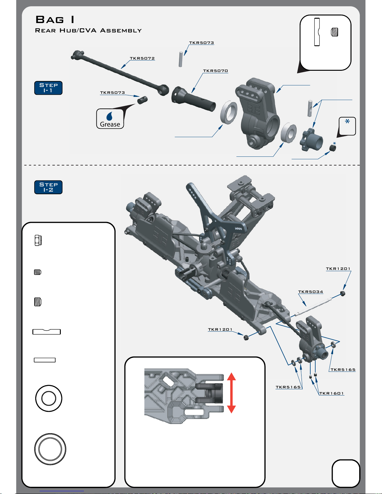
TKR5072
TKR5073
TKR5070
TKR5073
TKR5034
TKR1201
TKR1201
TKR1601
TKR5165
TKR5165
TKR5073
CV Joint Pin
x2
TKR1201
M3 Locknut Black
x4
Grease
Step
I-1
Step
I-2
Changes to the wheelbase have a dramatic eect on handling,
since it shifts the disribution of weight over the rear wheels.
This adjusts traction. By shortening the wheelbase at the rear, you
are placing more weight over the rear wheels.
Changes to the wheelbase also change the amount of sweep the
rear driveshaft will have. More driveshaft sweep creates an eect
similar to anti-squat, where the rear end gets pushed upwards on
throttle. This helps reduce chassis slap when landing jumps on throttle.
(FRONT)
(REAR)
TKR1603
M5x4mm Set Screw
x2
TKRBB13194
Ball Bearing (13x19x4)
x2
TKRBB08165
Ball Bearing (8x16x5)
x2
TKR5071X
M3x13.8mm Pin
x2
TKR1601
M3x4mm Set Screw
x4
Bag I
Rear Hub/CVA Assembly
11
Thread
Lock
Note: Notch on pin
needs to line up
with set screw.
TKR5199
TKRBB13194
TKRBB08165
TKR5071X
(Option)
*TKR5071B
*TKR5071C
(Option)
*TKR5199A
TKR1603
Page 12
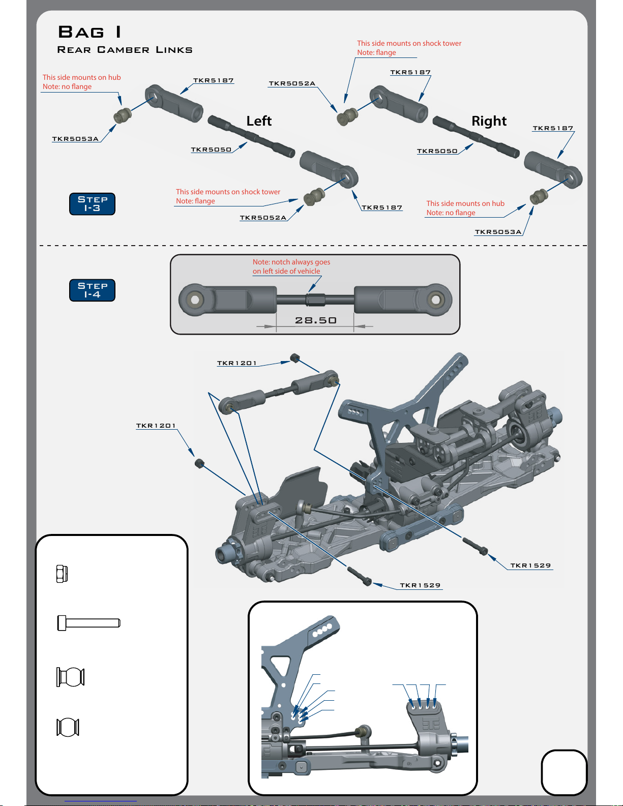
TKR5187
TKR5050
TKR5187
TKR5052A
This side mounts on hub
Note: no ange
This side mounts on shock tower
Note: ange
TKR5053A
28.50
Note: notch always goes
on
left side of vehicle
1
2
3
4
5
A
B
C
Stock position is 4/B
TKR1529
TKR1201
Right
TKR5053A
This side mounts on hub
Note: no ange
This side mounts on shock tower
Note: ange
TKR5187
Left
TKR1201
TKR1529
TKR5050
D
TKR1201
M3 Locknut Black
x4
TKR1529
M3x20mm Cap Head Screw
x4
TKR5053A
Pivot Ball M3x6.8mm
No Flange
x2
TKR5052A
Pivot Ball M3x6.8mm
x2
TKR5187
TKR5052A
Step
I-3
Step
I-4
Bag I
Rear Camber Links
12
Page 13
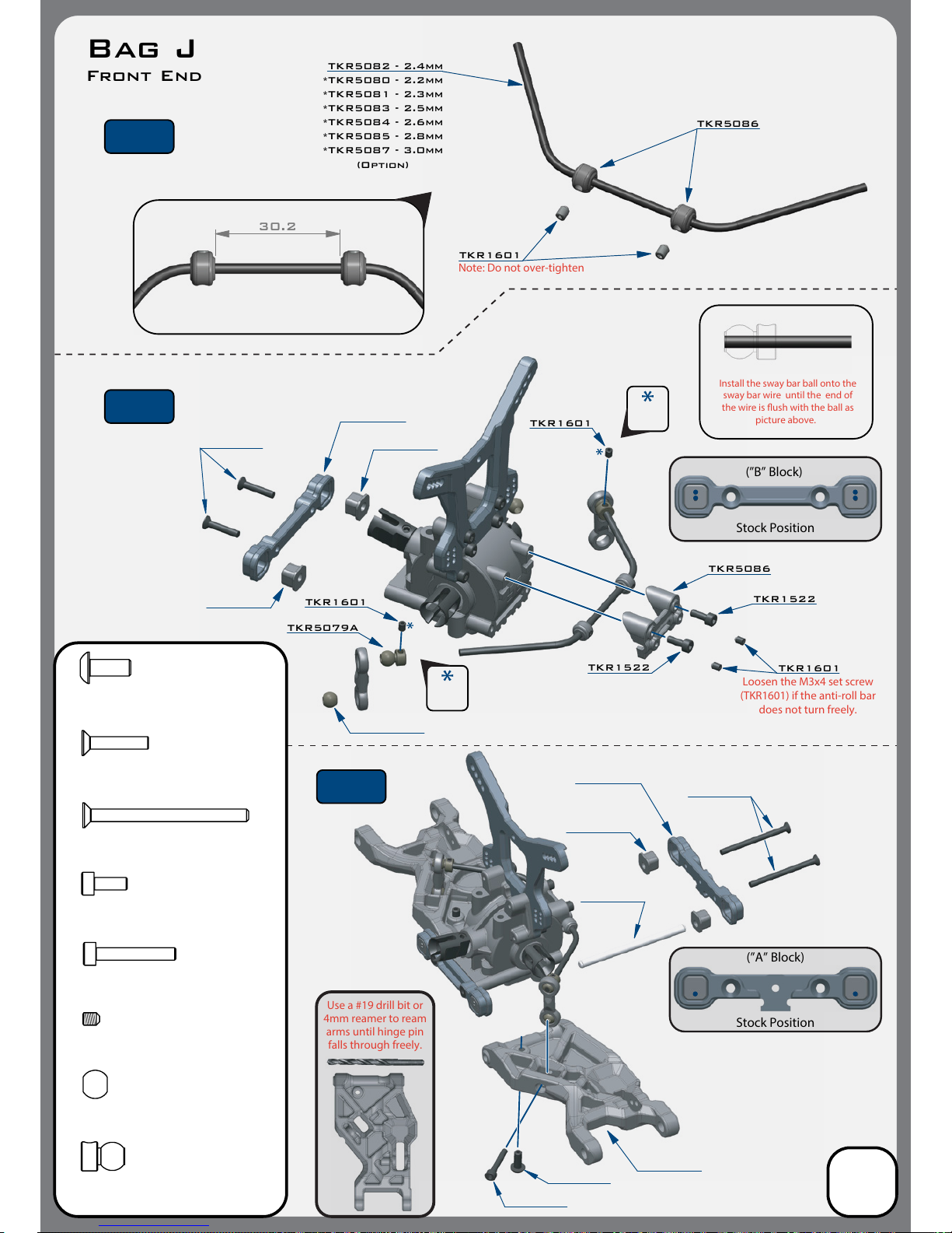
Use a #19 drill bit or
4mm reamer to ream
arms until hinge pin
falls through freely.
Stock Position
(”B” Block)
Stock Position
(”A” Block)
30.2
TKR1601
TKR1601
TKR1601
TKR5086
TKR5082 - 2.4mm
TKR5086
Install the sway bar ball onto the
sway bar wire until the end of
the wire is ush with the ball as
picture above.
Loosen the M3x4 set screw
(TKR1601) if
the anti-roll bar
does not
turn freely.
Note: Do not over-tighten
TKR1601
TKR5079A
TKR1522
TKR1522
TKR1522
M3x8mm Cap Head Screw
x2
Bag J
Front End
*TKR5080 - 2.2mm
*TKR5081 - 2.3mm
*TKR5083 - 2.5mm
*TKR5084 - 2.6mm
*TKR5085 - 2.8mm
*TKR5087 - 3.0mm
(Option)
Thread
Lock
Thread
Lock
13
TKR1327
TKR1333
M3x40mm Flat Head Screw
x2
TKR1238
M4x10mm Droop Screw
x2
TKR5049A
Pivot Ball Sway Bar
x2
TKR5079A
Stabilizer Ball
x2
TKR1529
M3x20mm Cap Head Screw
x2
TKR1327
M3x16mm Flat Head Screw
x2
TKR1333
TKR1529
TKR1238
TKR5020
TKR1601
M3x4mm Set Screw
x6
Step
J-1
Step
J-2
Step
J-3
TKR5162
TKR5161
TKR5286
TKR5165
TKR5149A
TKR5165
TKR5165
Note: With these stock settings,
Kick Up = 8.5° / Arm Sweep = 0°
For reference, with center dot
inserts in both braces,
Kick Up = 10° / Arm Sweep = 0°
Page 14
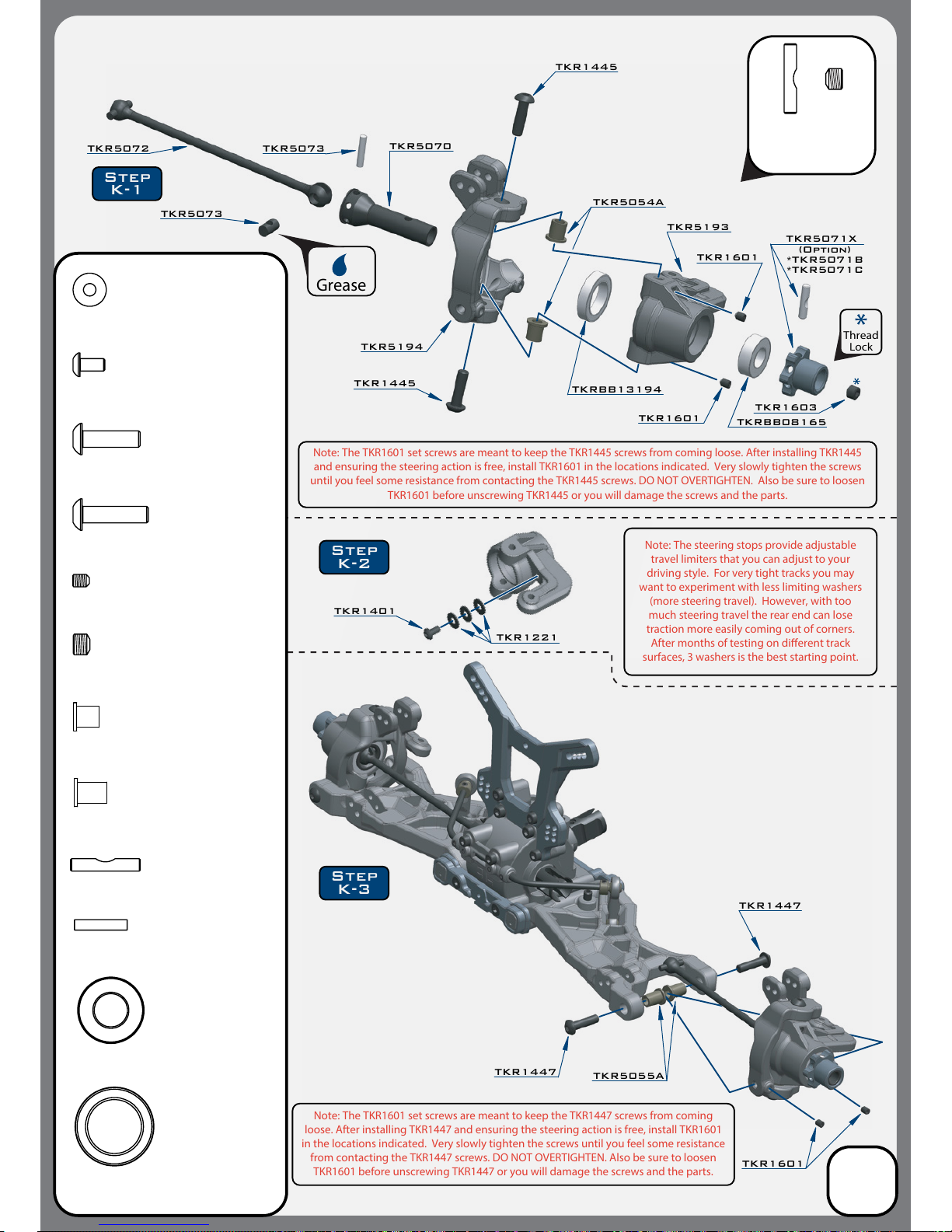
TKR5072
TKR5193
TKR5054A
TKR1445
TKRBB08165
TKR5194
TKR5070
TKR1447
TKR1447
TKR1601
TKR1601
TKR1601
TKRBB13194
TKR1221
TKR1401
TKR1445
TKR5054A
Spindle Pin Sleeve
x4
TKR5055A
Suspension Pin Sleeve
x4
Grease
TKR5073
TKR5073
Step
K-1
Step
K-3
Step
K-2
Thread
Lock
TKR5071X
TKR1603
(Option)
*TKR5071B
*TKR5071C
TKR1445
M4x14mm Button Head Screw
x4
TKR1447
M4x16mm Button Head Screw
x4
TKR5073
CV Joint Pin
x2
TKR1603
M5x4mm Set Screw
x2
TKRBB13194
Ball Bearing (13x19x4)
x2
TKRBB08165
Ball Bearing (8x16x5)
x2
TKR5071X
M3x13.8mm Pin
x2
TKR1601
M3x4mm Set Screw
x8
TKR5055A
Note: The steering stops provide adjustable
travel limiters that you can adjust to your
driving style. For very tight tracks you may
want to experiment with less limiting washers
(more steering travel). However, with too
much steering travel the rear end can lose
traction more easily coming out of corners.
After months of testing on dierent track
surfaces, 3 washers is the best starting point.
Note: The TKR1601 set screws are meant to keep the TKR1445 screws from coming loose. After installing TKR1445
and ensuring the steering action is free, install TKR1601 in the locations indicated. Very slowly tighten the screws
until you feel some resistance from contacting the TKR1445 screws. DO NOT OVERTIGHTEN. Also be sure to loosen
TKR1601 before unscrewing TKR1445 or you will damage the screws and the parts.
Note: The TKR1601 set screws are meant to keep the TKR1447 screws from coming
loose. After installing TKR1447 and ensuring the steering action is free, install TKR1601
in the locations indicated. Very slowly tighten the screws until you feel some resistance
from contacting the TKR1447 screws. DO NOT OVERTIGHTEN. Also be sure to loosen
TKR1601 before unscrewing TKR1447 or you will damage the screws and the parts.
TKR1401
M3x6mm Button Head Screw
x2
Bag K
Front Spindle / CVA Assembly
14
Note: Notch on pin
needs to line up
with set screw.
TKR1221
M3x8mm Washer
x8
Page 15
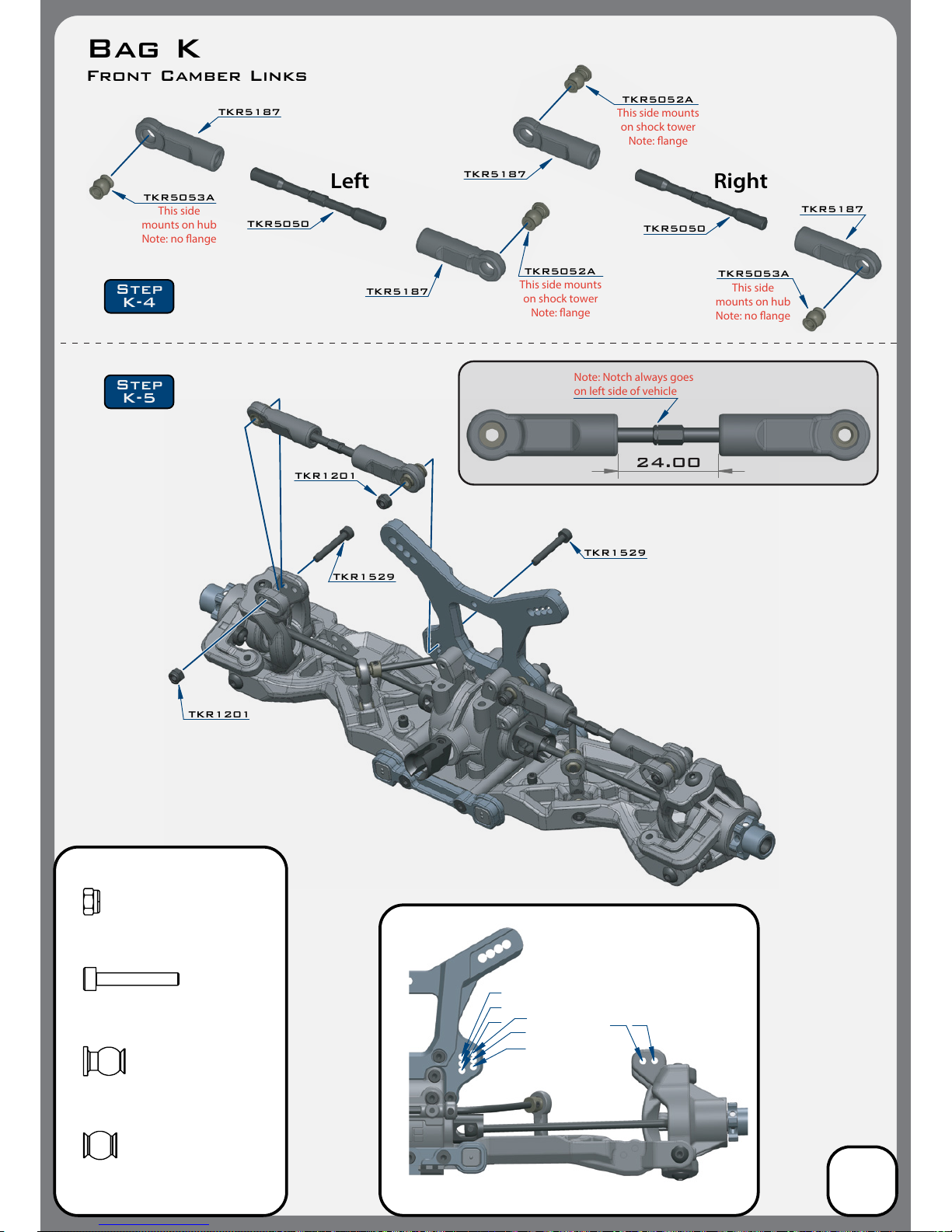
TKR1529
Stock position is 1/B
TKR1201
TKR1201
TKR1529
24.00
TKR1201
M3 Lock Nut Black
x4
TKR1529
M3x20mm Cap Head Screw
x4
TKR5052A
Pivot Ball M3x6.8mm
x2
TKR5053A
Pivot Ball M3x6.8mm
No Flange
x2
TKR5187
TKR5050
TKR5187
TKR5052A
TKR5053A
Right
TKR5187
This side
mounts on hub
Note: no ange
This side
mounts on hub
Note: no ange
This side mounts
on shock tower
Note: ange
This side mounts
on shock tower
Note: ange
TKR5187
Left
TKR5050
TKR5053A
TKR5052A
Note: Notch always goes
on
left side of vehicle
1
2
3
4
5
6
A
B
Step
K-5
Step
K-4
Bag K
Front Camber Links
15
Page 16
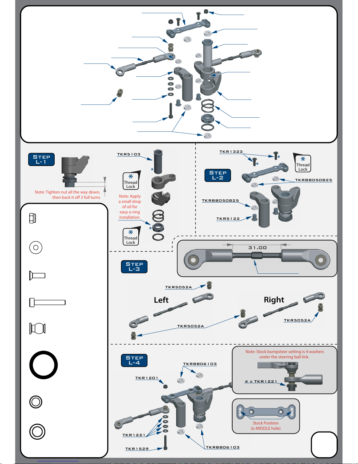
TKR1323
TKRBB050825
TKRBB050825
Note: Apply
a small drop
of oil for
easy o-ring
installation.
Note: Tighten nut all the way down,
then back it o 3 full turns
Stock Position
(is MIDDLE hole)
TKR5100
TKR5056
TKR5123
TKR5052A
TKR5104
TKR5104
TKR5101X
TKR5231
TKR1201
TKRBB06103
TKRBB06103
TKR1529
Note: Stock bumpsteer setting is
4 washers
under the steering ball link.
4 x TKR1221
TKR1221
TKRBB06103
TKRBB050825
TKR5104
TKR5122
TKR1529
TKR1221
TKR5103
TKR5103
TKR1201
TKRBB06103
TKR5052A
31.00
TKR1323
M3x10mm Flat Head Screw
x2
TKR1201
M3 Lock Nut Black
x2
O-ring 16x12x2
TKR5231
x1
TKRBB06103
Ball Bearing (6x10x3)
x4
TKRBB050825
Ball Bearing (5x8x2.5)
x4
TKR1529
M3x20mm Cap Head Screw
x2
TKR5052A
Pivot Ball M3x6.8mm
x4
TKR1221
M3x8mm Washer
x8
TKR5052A
TKR5052A
TKR5052A
Thread
Lock
Thread
Lock
Thread
Lock
Right
Left
Step
L-1
Step
L-2
Step
L-3
Step
L-4
Bag L
Steering Assembly
(overview)
16
Note: Notch always goes
on
left side of vehicle
Page 17
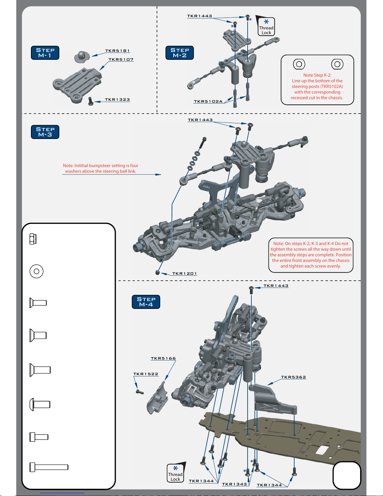
TKR5107
TKR1323
TKR1201
TKR1443
TKR5102A
TKR1443
Note: On steps K-2, K-3 and K-4 Do not
tighten the
screws all the way down until
the assembly steps are complete. Position
the entire front assembly on the chassis
and tighten each screw evenly.
TKR1522
TKR5166
TKR1443
TKR1344
TKR1344
TKR1343
TKR5362
Note: Inititial bumpsteer setting
is four
washers above the steering ball link.
TKR5181
TKR1522
M3x8mm Cap Head Screw
x1
TKR1343
M4x10mm Flat Head Screw
x2
TKR1344
M4x12mm Flat Head Screw
x6
TKR1201
M3 Lock Nut Black
x2
TKR1323
M3x10mm Flat Head Screw
x1
TKR1443
M4x10mm Button Head Screw
x5
TKR1529
M3x20mm Cap Head Screw
x2
TKR1221
M3x8mm Washer
x8
Note Step K-2:
Line up the bottom of the
steering posts (TKR5102A)
with the corresponding
recessed cut in the
chassis.
Thread
Lock
Thread
Lock
Step
M-3
Step
M-4
Step
M-1
Step
M-2
Bag M
Front End Assembly
17
Page 18
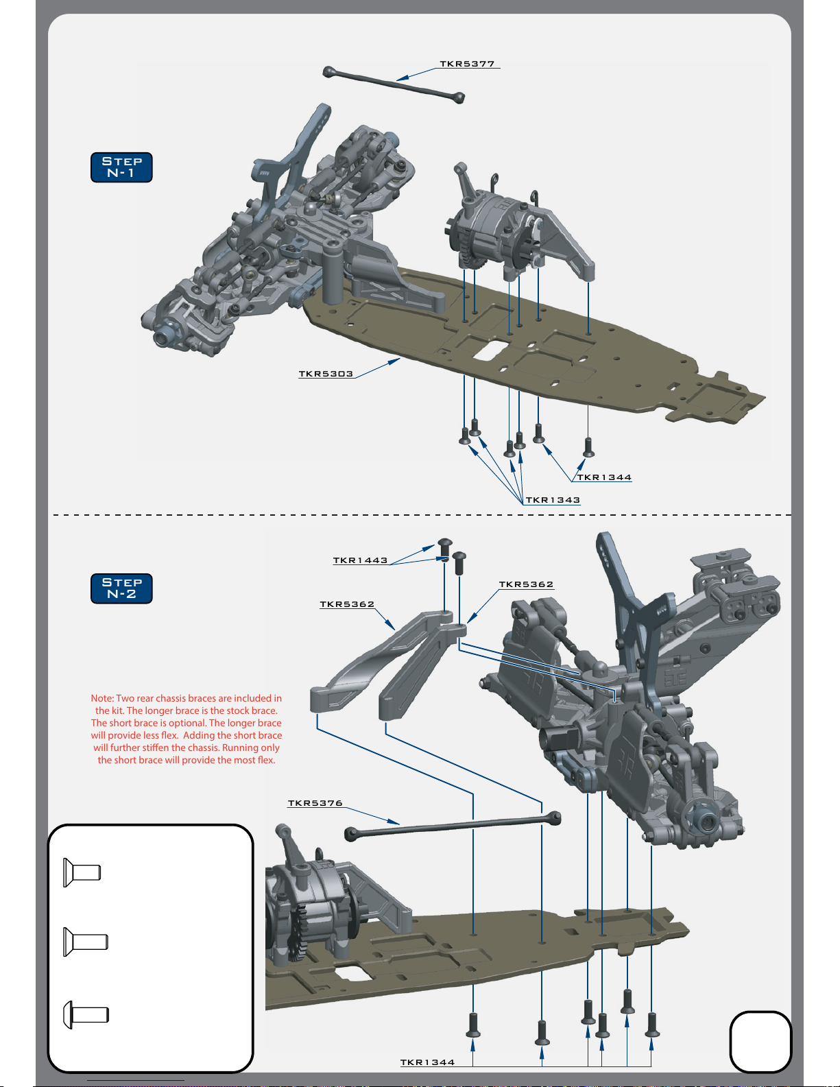
TKR5377
TKR1443
TKR1343
TKR5362
TKR1344
TKR5362
TKR1344
TKR5376
TKR1343
M4x10mm Flat Head Screw
x4
TKR1443
M4x10mm Button Head Screw
x2
TKR1344
M4x12mm Flat Head Screw
x8
Step
N-1
Step
N-2
TKR5303
Note: Two rear chassis braces are included in
the kit. The longer brace is the stock brace.
The short brace is optional. The longer brace
will provide less ex. Adding the short brace
will further stien the chassis. Running only
the short brace will provide the most ex.
Bag N
Center/Rear Assembly
18
*TKR5377A
(Option)
*TKR5376A
(Option)
Page 19
19
Shock Filling Instructions
For both front and rear shocks
The following steps and information will provide you with the best way to ll and bleed your
shocks. After thorough testing, we've found it's easiest to complete steps 1 through 3 on each
shock before moving onto step 4. By the time you've nished step 3 on the last shock the rst
one will be ready for step 4.
Standard or Vented Cap Build:
Step 1: Extend the shock shaft all the way down. Fill the shock with oil until the it is about 90% full.
Step 2: Slowly pump the shock shaft up and down 3-5 times to release air bubbles from underneath
the piston.
Step 3: Let the shock rest vertically with the shock shaft fully extended for ve minutes or until all
the air bubbles have released.
Step 4: Next you will top o the shock with oil, to about 1-2mm below the top edge.
(If you do overll the shock, it won’t hurt performance, it will just spill out and make a little bit of a
mess. If you underll the shock, it will cause air to be trapped inside.)
Step 5: Place the bladder INSIDE the shock cap and put a few drops of oil on the bladder.
Step 6: Put a paper towel down below the build to catch drips and have another ready to
wipe o excess oil. Place the cap on the shock and screw down about half way. Lay the shock
over about 45 degrees with the bleeder hole facing up.
Step 6A: (Standard non-vented) Push the shaft in for the amount of rebound desired.
Step 6B: (Vented “Stock”) Push the shaft in until about 15mm of shaft is showing.
• Make sure that you match the rebound amount between the left and right shocks.
• Oil should be oozing out of the bleeder hole.
Step 7: Hold the cap rmly in place with the bleeder hole facing up and turn the shock body until
hand tight. The shock will continue to ooze oil.
Step 8: Fully tighten down each shock with shock tools until cap is secure and wipe excess oil away.
Emulsion Build:
Prep your shock caps TKR6018 (optional for NB48.3) accordingly by drilling out the large angled
bleeder hole in the top of the cap. Place the larger thin o-ring around the base of the threads
where the shock cap screws on (see diagram on the next page). This seal is crucial to the build.
Follow steps 1-4 above.
Step 5: Rebound is more of a natural side eect of an emulsion shock. It’s not something that can
be set accurately because you run the risk of hydrolocking the shock if you do not push the shaft
all the way in when you bleed it. For now leave the shaft fully extended.
Step 6: Fill the shock up, over lling just slightly without spilling to create a small dome of oil.
Step 7: Place a little bit of oil in the shock cap and quickly put the shock cap on the shock body.
Tighten the cap all the way down. Very slowly push the shaft in. Oil will start to bleed out of the top
of the cap. While wiping away excess oil, continue to slowly push the shaft in ALL THE WAY.
If no oil comes out when the shaft is fully inserted, you will need to start over at step 6.
Step 8: Install the TKR1341 M4x6mm at head screw and TKR5125 black o-ring to seal
the cap (see diagram). Tighten until o-ring is fully seated.
Page 20
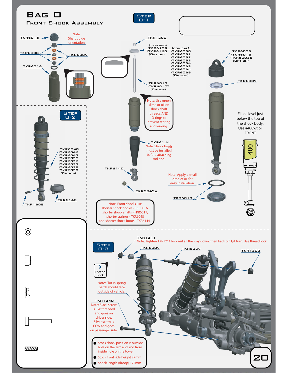
TKR6048
TKR6140
TKR1240
TKR1202
Note: Slot in spring
perch should face
outside of vehicle.
Note: Black screw
is CW threaded
and goes on
driver side.
Silver screw is
CCW and goes
on passenger side.
TKR1605
TKR6015
TKR6008
TKR6009
TKR6016
M2.5 Lock Nut Zinc
TKR1200
x2
TKR1240
M3x18mm Shock Mnt Screw
x2
TKR1211
M3 Lock Nut Flange Black
x2
*TKR6046
*TKR6047
*TKR6035
*TKR6036
*TKR6037
*TKR6038
*TKR6039
(Option)
Note:
Shaft guide
orientation
Note:
Front shocks use
shorter shock bodies -
TKR6016,
shorter shock shafts -
TKR6017,
shorter springs -
TKR6048
and shorter shock boots -
TKR6144
Step
O-1
Step
O-2
Step
O-3
TKR1200
TKR6159 (conical)
(tapered)
TKR6017
TKR5049A
*TKR6017T
(Option)
*TKR6160
(Option)
*TKR6050
*TKR6051
*TKR6052
*TKR6053
*TKR6054
*TKR6063
*TKR6064
*TKR6065
(Option)
Note: Use green
slime or oil on
shock shaft
threads AND
O-rings to
prevent tearing
and leaking.
TKR6140
TKR6144
Note: Shock boots
must be installed
before attaching
rod end.
TKR1202
M4 Lock Nut Black
x2
TKR1211
TKR6007
TKR5027
Note: Tighten TKR1211 lock nut all the way down, then back o 1/4 turn. Use thread lock!
Thread
Lock
TKR6003
TKR6009
TKR6013
*TKR6018
*TKR6003B
(Option)
Note: Apply a small
drop of oil for
easy installation.
Fill oil level just
below the
top of
the shock body.
Use #400wt oil
FRONT
400
Note:
Tapered side up
Bag O
Front Shock Assembly
20
Stock shock position is outside
hole on the arm and 2nd from
inside hole on the tower
Stock front ride height 27mm
Shock length (droop) 122mm
TKR1605
M3x10mm Set Screw
x2
Note:
Make sure to tighten both cartridge cap
(TKR6015) and shock cap (TKR6003) to ensure
a proper seal. Tools may be required.
Page 21
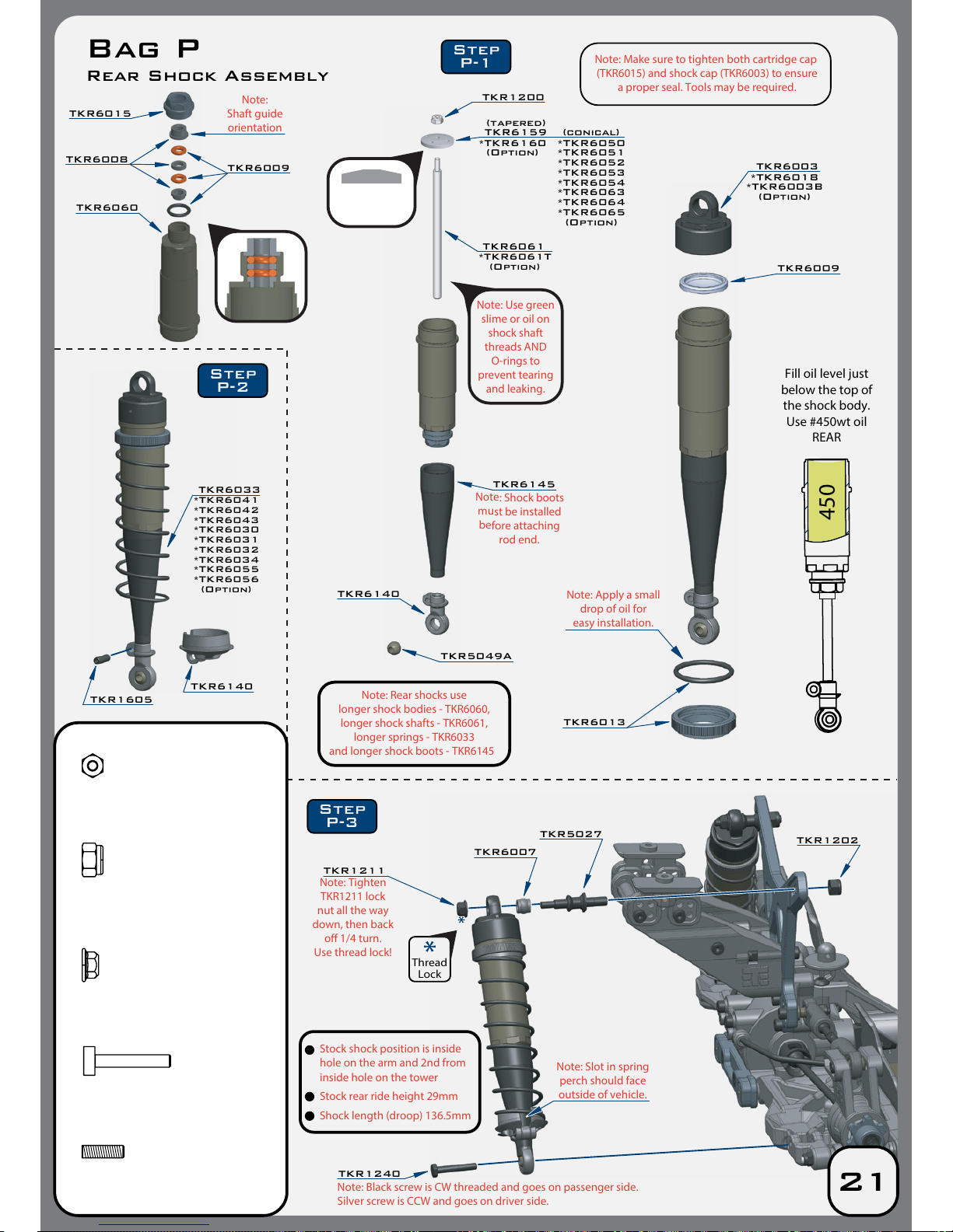
TKR6033
TKR6140
TKR6007
TKR5027
Note: Slot in spring
perch should face
outside of vehicle.
TKR1202
TKR1605
TKR6015
TKR6009
TKR6060
M2.5 Lock Nut Zinc
TKR1200
x2
TKR1211
M3 Lock Nut Flange Black
x2
*TKR6041
*TKR6042
*TKR6043
*TKR6030
*TKR6031
*TKR6032
*TKR6034
*TKR6055
*TKR6056
(Option)
TKR6061
TKR5049A
*TKR6061T
(Option)
Note:
Shaft guide
orientation
Note:
Rear shocks use
longer shock bodies -
TKR6060,
longer shock shafts -
TKR6061,
longer springs -
TKR6033
and longer shock boots -
TKR6145
Note: Use green
slime or oil on
shock shaft
threads AND
O-rings to
prevent tearing
and leaking.
Step
P-1
Step
P-2
Step
P-3
TKR6145
Note: Shock boots
must be installed
before attaching
rod end.
TKR1202
M4 Lock Nut Black
x2
TKR1211
Note: Tighten
TKR1211 lock
nut all the way
down, then back
o 1/4 turn.
Use thread lock!
Thread
Lock
TKR6003
TKR6009
TKR6013
*TKR6018
*TKR6003B
(Option)
Note: Apply a small
drop of oil for
easy installation.
TKR1240
Note: Black screw is CW threaded and goes on passenger side.
Silver screw is CCW and goes on driver side.
TKR1240
M3x18mm Shock Mnt Screw
x2
Fill oil level just
below the
top of
the shock body.
Use #450wt oil
REAR
450
TKR1200
TKR6159 (conical)
(tapered)
*TKR6160
(Option)
*TKR6050
*TKR6051
*TKR6052
*TKR6053
*TKR6054
*TKR6063
*TKR6064
*TKR6065
(Option)
TKR6008
Note:
Tapered side up
TKR6140
Bag P
Rear Shock Assembly
21
Stock shock position is inside
hole on the arm and 2nd from
inside hole on the tower
Stock rear ride height 29mm
Shock length (droop) 136.5mm
TKR1605
M3x10mm Set Screw
x2
Note:
Make sure to tighten both cartridge cap
(TKR6015) and shock cap (TKR6003) to ensure
a proper seal. Tools may be required.
Page 22
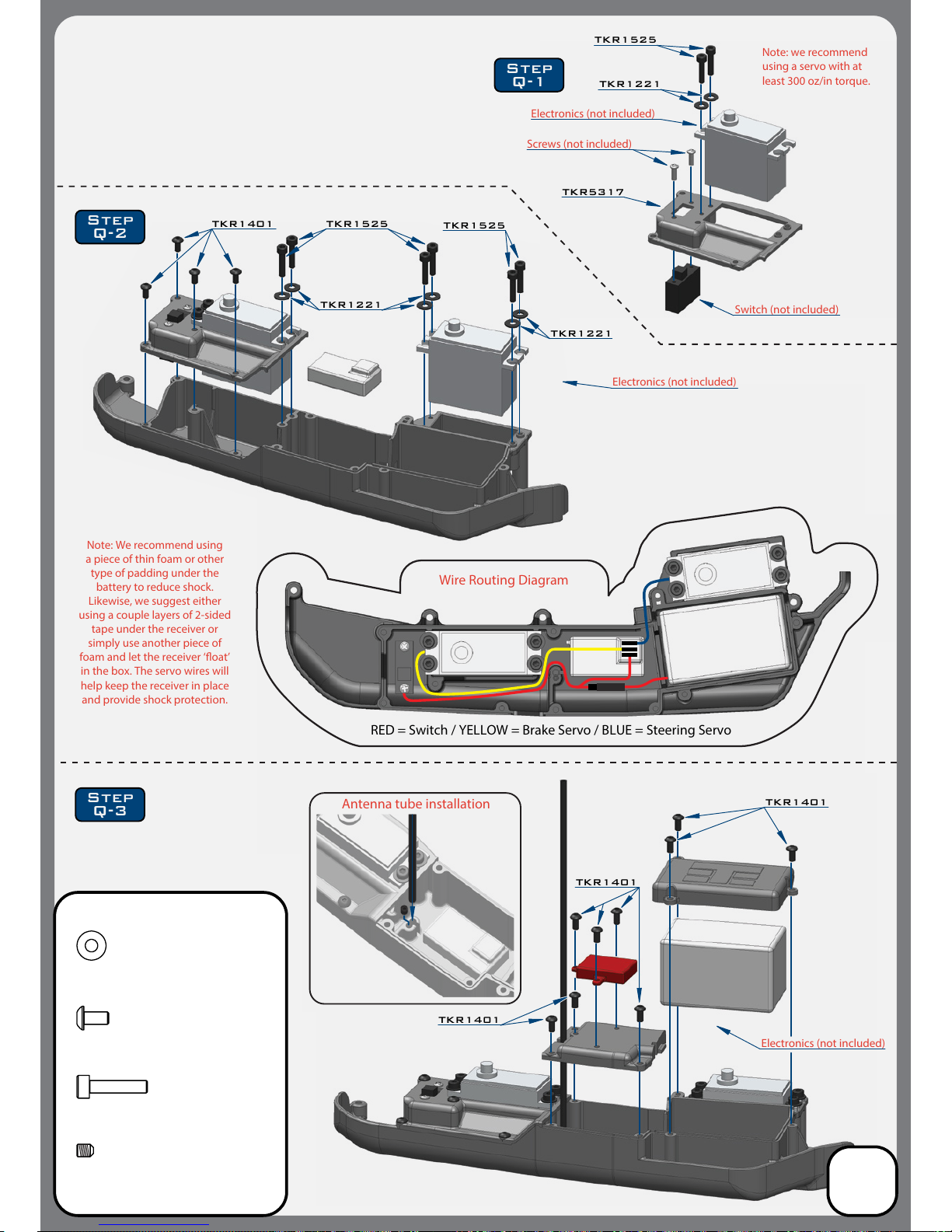
Electronics (not included)
Note: we recommend
using a servo with at
least 300 oz/in torque.
Screws (not included)
TKR1401
TKR1401
TKR1401
TKR1525
TKR1525
TKR1401
TKR5317
Switch (not included)
Electronics (not included)
Note: We recommend using
a piece of thin foam or other
type of padding under the
battery to reduce shock.
Likewise, we suggest either
using a couple layers of 2-sided
tape under the receiver or
simply use another piece of
foam and let the receiver ‘oat’
in the box. The servo wires will
help keep the receiver in place
and provide shock protection.
RED = Switch / YELLOW = Brake Servo / BLUE = Steering Servo
Wire Routing Diagram
Electronics (not included)
TKR1525
TKR1401
M3x6mm Button Head Screw
x13
TKR1525
M3x14mm Cap Head Screw
x8
TKR1221
M3X8mm Washer
x8
TKR1221
TKR1221
TKR1221
Step
Q-3
Step
Q-2
Step
Q-1
TKR1601
M3x4mm Set Screw
x6
Antenna tube installation
Bag Q
RX Tray Mud Guard
22
Page 23
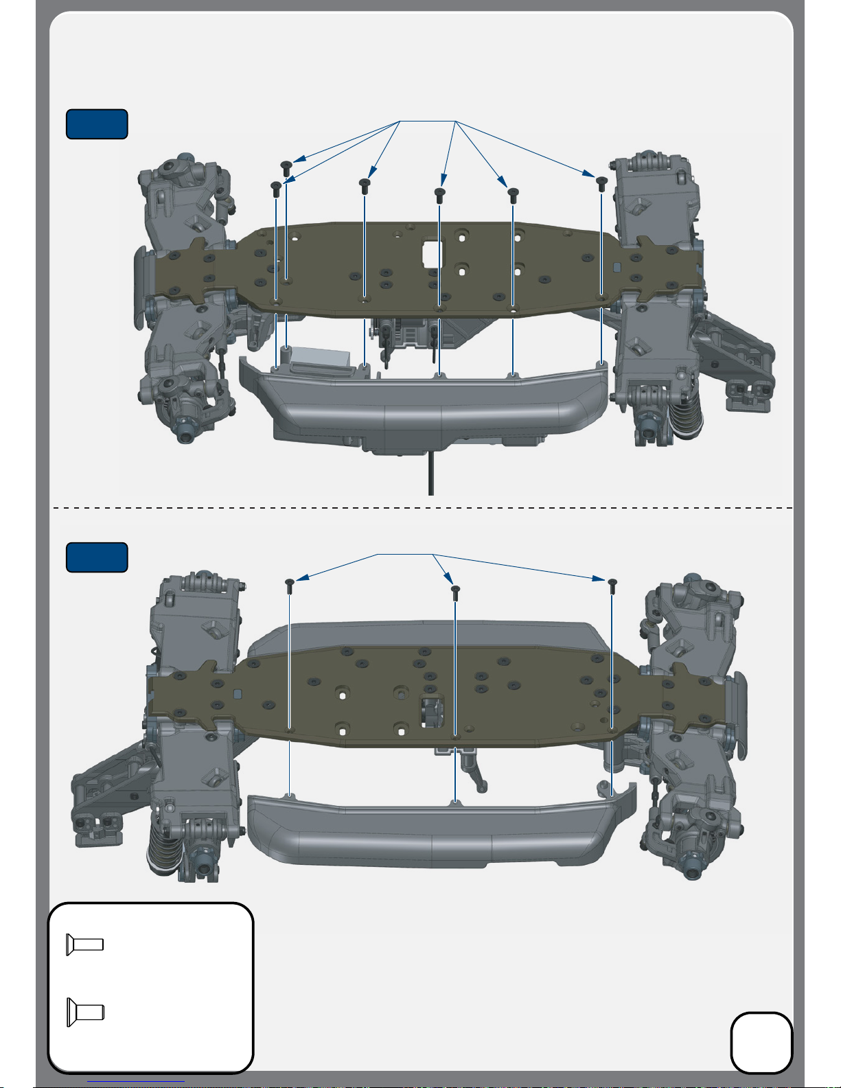
TKR1343
M4x10mm Flat Head Screw
X6
TKR1323
M3x10mm Flat Head Screw
x3
Bag Q
Mud Guard Installation
23
Step
Q-5
Step
Q-4
TKR1323
TKR1343
Note: Do not overtighten radio tray screws.
Note: Do not overtighten radio tray screws.
Page 24
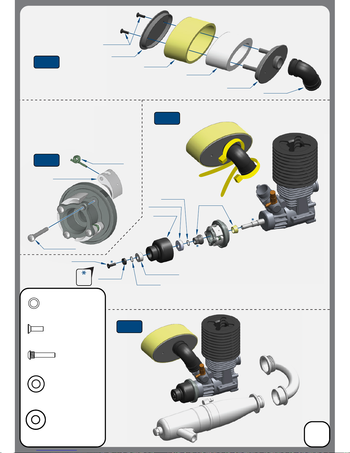
Bag R
Air Filter / Clutch
24
Step
R-1
Step
R-2
Step
R-3
Step
R-4
TKR1323
M3x10mm Flat Head Screw
x3
TKR1323
TKR1323
TKR5353
TKR5353 x4
TKR5353
TKR1226
TKRBB05115
TKRBB05134
TKR4215
TKR1226
TKR5353 X4
TKR5351 x4
TKR5324
TKR5324
TKR5324
TKR5324
TKR5324
TKR5353
Clutch Pin
x4
Engine and Pipe Sold Separately
Engine and Pipe Sold Separately
Manifold and pipe springs not
shown or included
TKRBB05115
Ball Bearing (5x11x5)
x1
TKR1226
5x7x0.2mm shim
x4
TKRBB05134
Ball Bearing (5x13x4)
x1
*TKR5363
(Option)
(foams only)
*TKR5363
(Option)
(foams only)
Note: Your kit contains 3 sets of clutch springs. 0.9mm
(green), 1.0mm (gold), and 1.1mm (red) springs are
included. The stock setting is to use (2x) 0.9mm springs
on opposing shoes and then use (2x) 1.0mm springs on
the other shoes. If the track is very high bite you can use
(2x) 1.0mm springs and (2x) 1.1mm springs for more
‘pop’. However, we strongly recommend trying the
stock setting rst and adjusting from there.
Note: Properly shimming the clutch bell is critical. The clutch bell must
not rub on the ywheel. Depending on your particular engine, you may
need to use a few of the 5x7x.2mm shims (TKR1226) to properly space the
clutch bell. The clutch bell must also move freely when the end washer and
screw are fastened. There is no ‘one size ts all’ for the number and order of
clutch bell shims that need to be used. In rare cases, the clutch bell may be
too long. Simply put the clutch bell at on a sheet of 200 grit sand paper
(teeth side up) and sand about .2mm o the bottom. This should only take a
minute and it will ensure that your clutch is working properly.
Note: Secure air lter hose
with 2 zip ties (included).
Thread
Lock
Page 25
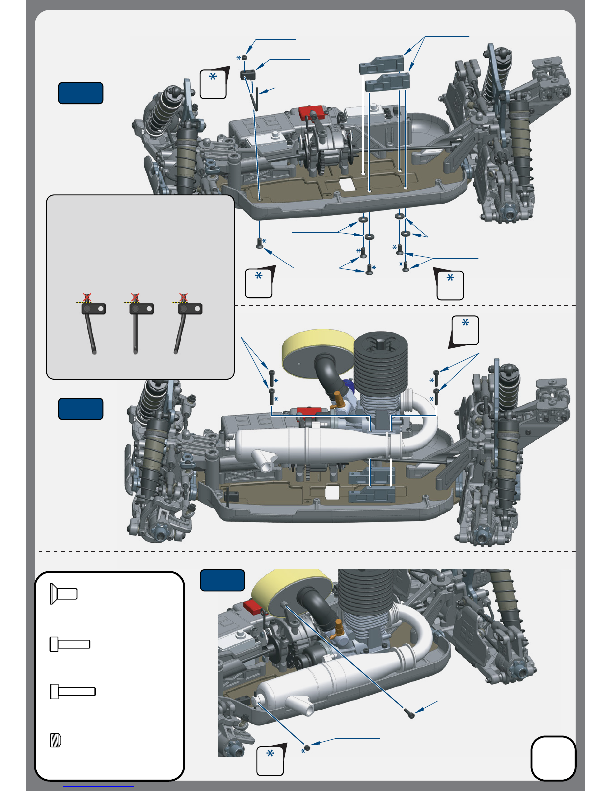
TKR1343
M4x10mm Flat Head Screw
X5
TKR1603
M5x4mm Set Screw
x1
TKR1524
M3x12mm Cap Head Screw
x1
Bag S
Engine / Pipe
Installation
25
Step
S-1
Step
S-2
Step
S-3
TKR5323
TKR1525
TKR1524
TKR1343
TKR1343
TKR1228
TKR1228
TKR1525
TKR1603
TKR5321
TKR5321
Set Screw
(not included)
*You may need to bend the pipe wire hanger forward
or backward depending on your particular pipe.
VERY IMPORTANT - With the set screws that secure the
pipe hanger wire set loose, install pipe onto pipe hanger
wire. Adjust the wire such that the pipe and the manifold
connections from the engine are not bent or angled. The
pipe must t naturally. You may need to bend the pipe
hanger wire to accomplish this. Then tighten the set
screw that secures the wire to the wire hanger block. The
wire must then be cut ush to the wire hanger block so it
will not interfere with the fuel tank. If the wire is not ush
with the block, you may risk puncturing your fuel tank.
! ! !
Thread
Lock
Thread
Lock
Thread
Lock
Thread
Lock
Thread
Lock
TKR1525
M3x14mm Cap Head Screw
x4
Page 26
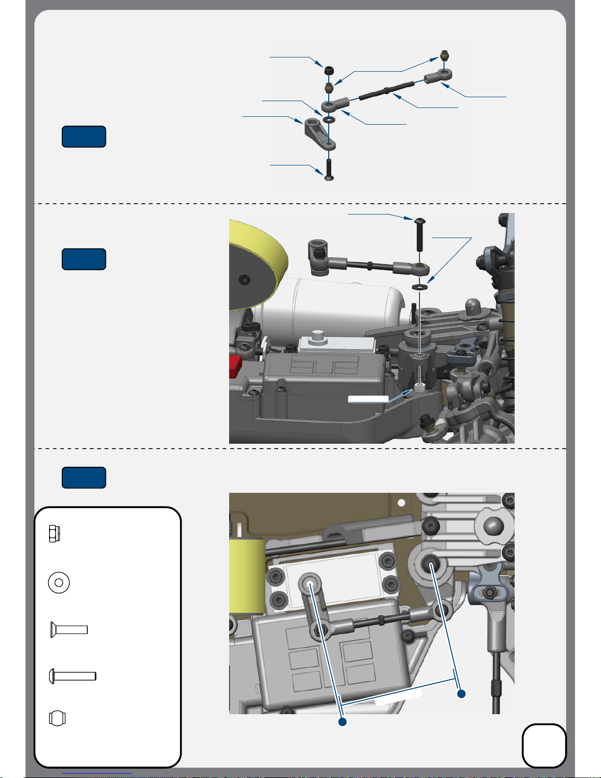
Bag T
Steering Linkage
26
Step
T-1
Step
T-2
Step
T-3
TKR5058A
TKR5056
TKR5357
TKR5056
TKR1201
TKR1201
TKR1325
TKR5320
TKR1221
TKR1221
TKR1407
TKR1325
M3x14mm Flat Head Screw
x1
TKR1201
M3 Lock Nut Black
x2
Note: Oset servo arm so it is parallel with the connecting arm at neutral or zero servo position.
PARALLEL
TKR1221
M3x8mm Washer
x2
TKR5058A
Pivot Ball M3x5.8mm
No Flange
x2
TKR1407
M3x16mm Button Head Screw
x1
*TKR5251B
*TKR5252B
*TKR5253B
(Option)
Page 27
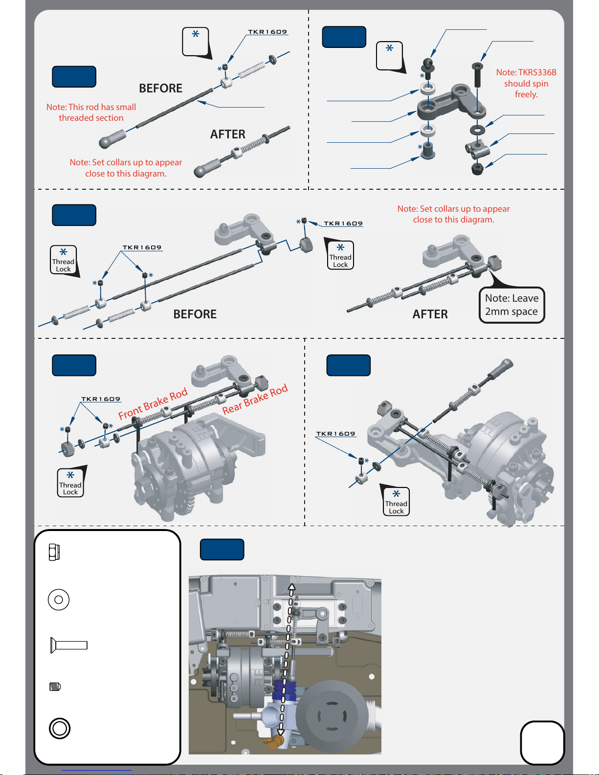
TKR1609
TKR1609
Note: Set collars up to appear
close to this diagram.
Note: Set collars up to appear
close to this diagram.
BEFORE AFTER
Thread
Lock
Thread
Lock
Thread
Lock
Thread
Lock
Note: Leave
2mm space
TKR1609
TKR1609
BEFORE
AFTER
Note: This rod has small
threaded section
Note: TKR5336B
should spin
freely.
TKR1609
Bag T
Brake Linkage
27
Step
T-4
Step
T-5
Step
T-6
Step
T-7
Step
T-8
Step
T-9
TKR1201
TKR5336B
TKR5336B
TKR1201
TKR5331
TKR1325
TKR5320
TKR5331
TKRBB050825
TKRBB050825
TKR1325
M3x14mm Flat Head Screw
x1
TKR1201
M3 Lock Nut Black
x1
TKR1221
M3x8mm Washer
x1
TKRBB050825
Ball Bearing (5x8x2.5)
x2
TKR1609
M3x3mm Set Screw
x7
Thread
Lock
Thread
Lock
NOTES:
• Align the carberator so it forms a
straight line to the servo linkage, with
the servo in the neutral position
• Attach all linkages before setting
brake bias
• All collars should be snug against the
springs without being compressed
• Turn on radio equipment for nal
adjustment of collars, total brake force,
F/R brake bias, and throttle EPA
• Brakes should be fully disengaged and
the carburetor should be fully
closed at neutral position
Page 28
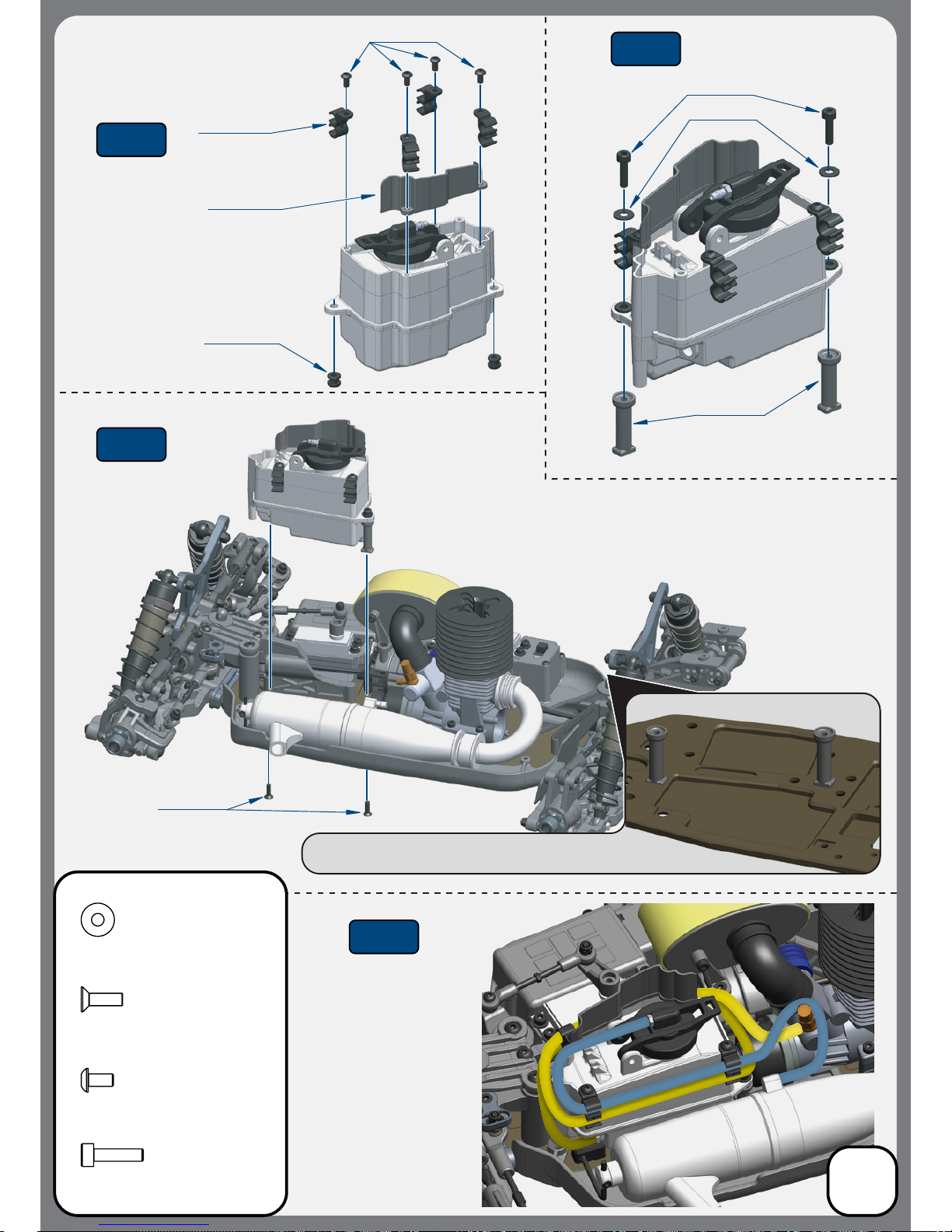
Bag U
Fuel Tank
28
Step
U-1
Step
U-2
Step
U-3
Step
U-4
TKR1524
TKR5340B
TKR5340B
TKR5340B
TKR1401
TKR5341
TKR1323
TKR1221
TKR1524
M3x12mm Cap Head Screw
x2
TKR1323
M3x10mm Flat Head Screw
x2
TKR1401
M3x6mm Button Head Screw
x4
TKR1221
M3x8mm Washer
x2
*Align the fuel tank posts to the cutouts in the chassis
Note: Fuel tubing
wraps around the
tank 1 1/2 times
from the pick up
nipple (yellow line).
Pressure line is
shown in blue.
Page 29
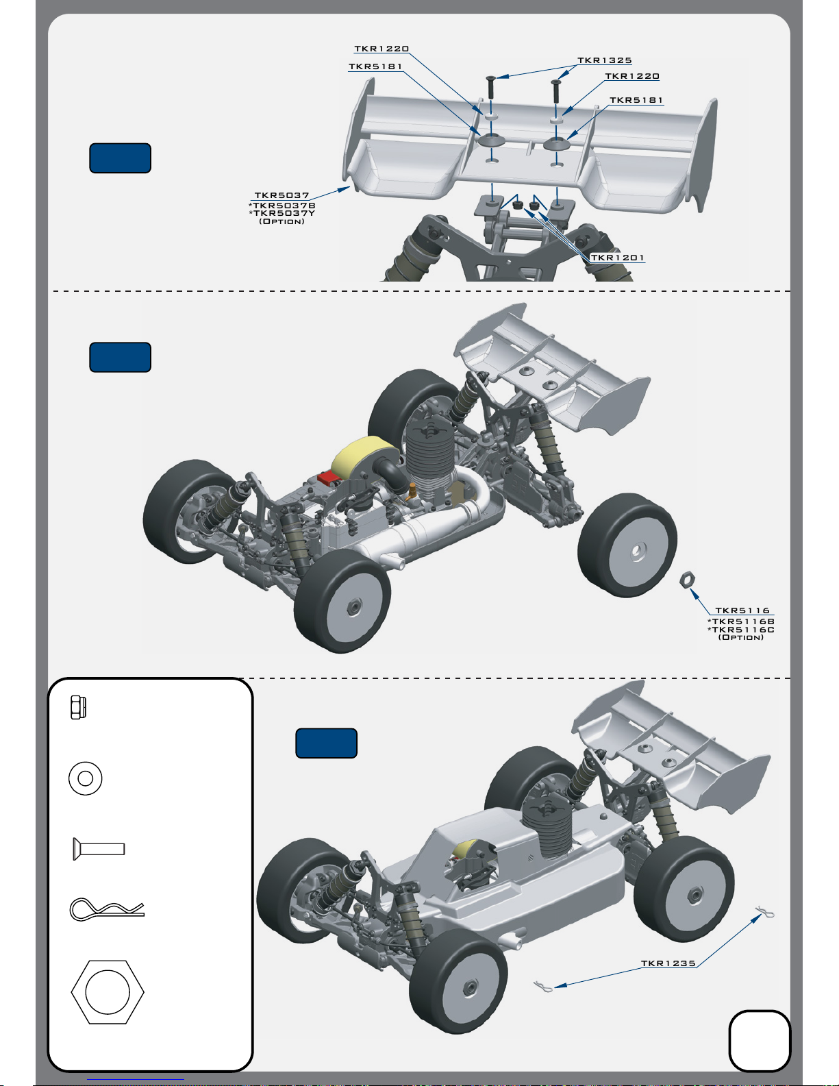
TKR5037
*TKR5037B
*TKR5037Y
(Option)
TKR1325
TKR1220
TKR5181
TKR1201
TKR5181
TKR1220
TKR5116
*TKR5116B
*TKR5116C
(Option)
TKR1235
TKR1325
M3x14mm Flat Head Screw
x2
TKR1201
M3 Lock Nut Black
x2
TKR5116
Wheel Nut
x4
TKR1235
Body Clip
x2
Bag V
Wing and Body
29
Step
V-1
Step
V-2
Step
V-3
TKR1220
M4 Countersunk Washer
X2
Page 30
30
Parts List
TKR4215 - Clutch Bell (15t, NB48)
TKR5012 – Gearbox (front)
TKR5020 – Hinge Pins (inner, front/rear)
TKR5027 – Shock Standos (2pcs)
TKR5034 – Hinge Pins (outer, rear)
TKR5037 – Wing (white)
TKR5049A – Pivot Balls (6.8mm, no ng, sway bar, shck ends, almnm, 4pcs)
TKR5052A – Pivot Balls (6.8mm, inside camber, steering links, aluminum, 4pcs)
TKR5053A – Pivot Balls (6.8mm, anged, outside camber, aluminum, 4pcs)
TKR5054A – Spindle Bushings (4pcs, aluminum, hard ano)
TKR5055A – Arm Bushings (4pcs, aluminum, hard ano)
TKR5056 – Rod Ends (5.8mm, brake/steering/sway bar linkage, 8pcs)
TKR5058A – Pivot Balls (5.8mm, no ange, brake/steering link, aluminum, 4pcs)
TKR5070 – Stub Axles (hardened steel, 2pcs)
TKR5071X – Wheel Hubs (17mm, aluminum, lightened, gun metal ano, w/pins, 2pcs)
TKR5072 – Driveshafts (f/r, hardened steel, 2pcs)
TKR5073 – CV Rebuild kit (f/r, for 2 axles)
TKR5075 – Di Coupler (f/r, hardened steel)
TKR5079A – Stabilizer Balls (6.8mm, sway bars, aluminum, 4pcs)
TKR5082 – Sway Bar (2.4mm, front)
TKR5086 – Sway Bar Mounts
TKR5100 – Ackerman Plate (aluminum, gun metal ano)
TKR101X - Servo Saver Spring (HD, EB48, SCT410, NB48)
TKR5102A – Steering Posts (aluminum)
TKR5103 – Servo Saver Post (aluminum, gun metal ano)
TKR5104 – Steering Bell Cranks
TKR5107 – Steering Top Plate, Center Di Top Plate, Center Di Rear Support
TKR5116 – Wheel Nuts (17mm, serrated, gun metal ano, M12x1.0, 4pcs)
TKR5122 – Steering Rack Bushings (aluminum, gun metal ano, 2pcs)
TKR5123 – Turnbuckle (steering links, 2pcs)
TKR5126 – Antenna tube (universal, w/ caps, 5pcs)
TKR5161 - V2 Adj. Hinge Pin Brace (”A” block, 7075, EB/NB/ET/NT/SCT)
TKR5162 - V2 Adj. Hinge Pin Brace (”B” block, 7075, EB/NB/ET/NT/SCT)
TKR5163 - V2 Adj. Hinge Pin Brace (”C” block, 7075, EB/NB/ET/NT/SCT)
TKR5164 - V2 Adj. Hinge Pin Brace (”D” block, 7075, EB/NB/ET/NT/SCT)
TKR5165 - V2 Hinge Pin Inserts, Wheelbase Shims (EB/NB/ET/NT/SCT)
TKR5166 - Front Bumper (revised, EB/NB/ET/NT48)
TKR5174 - Rear Arm Mud Guards (for TKR5184, EB/NB)
TKR5181 - Low Prole Wing Mount and Body Mounts (EB/NB48/EB48SL)
TKR5184 - Suspension Arms (rear, EB/NB48.3)
TKR5187 - Rod Ends (straight, 6.8mm, EB/NB/ET/NT48, 8pcs)
TKR5193 - Spindles (trailing, L/R, requires TKR5194, EB/NB/ET/NT48, EB/NB.3)
TKR5194 - Spindle Carriers (trailing, 15 degree, L/R, EB/NB/ET/NT48, EB/NB.3)
TKR5199 - Rear Hubs (L/R, CV or uni, EB/NB/ET/NT48, EB/NB.3)
TKR5213A – Brake Posts (aluminum, 4pcs)
TKR5215B – Brake Cams (10 deg, steel, 2pcs)
TKR5231 – Servo Saver Nut and Spring
TKR5268 - Shock Tower (front, 7075 CNC, gun metal ano, EB/NB48.3)
TKR5269 - Shock Tower (rear, 7075 CNC, gun metal ano, EB/NB48.3)
TKR5286 - Suspension Arms (front, EB/NB48.3)
TKR5303 – Chassis (7075, 4mm, hard anodized, lightened, NB48)
TKR5310 – Center Dierential Mount (NB48, NT48)
TKR5314B - Brake Pad Set (2pcs, NB/NT)
TKR5316 – Rear GearBox (oset, rear, NB48, NT48)
TKR5317 – Radio Tray and Mud Guard Set (left/right side, NB48, NT48)
TKR5319 – Radio Tray Covers (NB48, NT48)
TKR5320 - Servo Horns (steering, throttle, NB48, NT48)
TKR5321 - Exhaust Wire Mount Set (CNC, NB48, NT48)
TKR5323 - Engine Mounts (CNC, NB48, NT48)
TKR5324 - Air Filter Set (hose, lter, housing, NB48, NT48)
TKR5331 - Throttle Pivot Ball Assembly (CNC, NB48, NT48)
TKR5336B – Throttle, Brake Linkage (NB/NT, revised)
TKR5340B - Fuel Tank (w/ clunk, NB48, revised)
TKR5341 - Fuel Tank Post and Air Filter Hanger Set (NB48, NT48)
TKR5345B - Brake Disc (steel, NB/NT, revised, 1pc)
TKR5350 - Flywheel (4-shoe)
TKR5351 - Clutch Shoes (7075, 4pcs, NB48, NT48)
TKR5353 - Clutch Springs and Hardware Set (NB48, NT48)
TKR5357 - Steering Servo Turnbuckle (NB48, NT48)
TKR5362 - Chassis Brace Set (NB48, NT48)
TKR5363 - Air Filter Foams (inner, outer, pre-oiled, 3pcs each, NB48, NT48)
TKR5368 - Brake Post Spring (NB/NT, 4pcs)
TKR5376 - Driveshaft (center, rear, steel, NB48)
TKR5377 - Driveshaft (center, front, steel, NB48, NT48)
TKR5383 - Body (NB48, w/ window mask)
TKR5396 - Decal Sheet (NB48.3)
TKR5491 - Sway Bar (2.4mm, rear)
Dierential List
TKR5112X – Dierential Outdrives (center, lightened)
TKR5113 – Dierential Case (f/c/r)
TKR5114X – Dierential Outdrives (f/r, lightened)
TKR5119 – Spur Gear (46t, steel)
TKR5143 – Dierential Seals (3pcs)
TKR5144 – Dierential O-Rings (6pcs)
TKR5145B – Dierential Shims (revised, 6x17mm, 6pcs)
TKR5149 – Dierential Cross Pins (steel, 6pcs)
TKR5150 – Dierential Gear Set (internal gears only)
TKR5151 – Dierential Ring Gear (40t, straight cut)
TKR5152 – Di Pinion (10T, straight cut)
TKR5302 - Dierential Ring Gear (40t, rear, CNC, NB48)
Shocks List
TKR6003 – Vented Shock Caps (aluminum, black ano, 2pcs)
TKR6007 - Shock Cap Bushings (4pcs, EB/NB/ET/NT/SCT)
TKR6008 – Shock Shaft Guide, Piston, and Bushing Set (for 2 shocks)
TKR6009 – Shock O-Ring and Bladder Set (for 2 shocks)
TKR6013 – Shock Adjustment Nuts (aluminum, gun metal ano, 2pcs)
TKR6015 – Shock Cartridge Caps (aluminum, gun metal ano, 2pcs)
TKR6016 – Shock Body (rear, aluminum, hard ano, 2pcs)
TKR6017 – Shock Shafts (rear, steel, 2pcs)
TKR6033 – Shock Spring Set (rear, 1.4 x 9.5T, 85mm, orange)
TKR6048 – Shock Spring Set (front, 1.5 x 9.5T, 65mm, black)
TKR6060 – Shock Body (rear, x-long, aluminum, hard ano, 2pcs)
TKR6061 – Shock Shafts (rear, x-long, steel, 2pcs)
TKR6140 - Locking Shock Rod End and Spring Perch Set (EB/NB/ET/NT/SCT)
TKR6144 - Shock Boots (long length, EB/NB, 2pcs)
TKR6145 - Shock Boots (X-long length, rear EB/NB, 2pcs)
TKR5304 - NB48.3 1/8th Competition Nitro Buggy Kit
Bearings List
TKRBB050825 – Ball Bearing (5x8x2.5mm, 4pcs)
TKRBB05114 – Ball Bearing (5x11x4, 4pcs)
TKRBB05115 – Ball Bearing (5x11x5, 4pcs)
TKRBB05134 – Ball Bearing (5x13x4, 4pcs)
TKRBB06103 – Ball Bearing (6x10x3, 4pcs)
TKRBB08165 – Ball Bearing (8x16x5, 4pcs)
TKRBB13194 – Ball Bearing (13x19x4, 4pcs)
Hardware List
TKR1200 – M2.5 Locknuts (zinc nish, 10pcs)
TKR1201 – M3 Locknuts (black, 10pcs)
TKR1202 - M4 Locknuts (black, 10pcs)
TKR1211 – M3 Locknuts (anged, black, 10pcs)
TKR1220 – M3 Countersunk Washers (aluminum, natural, 10pcs)
TKR1221 – M3x8mm Washer (black, 10pcs)
TKR1222 – 13x16x.1mm Di Shims (10pcs)
TKR1226 - 5x7x.2mm shims (10pcs)
TKR1228 - M4 Countersunk Washer (black, 10pcs)
TKR1235 – Body Clips (10pcs)
TKR1238 - Droop Adjustment Screws (M4x10mm, 8pcs)
TKR1240 - Lower Shock Mount Screws (2 CW thread, 2 CCW thread, EB/NB/SCT)
TKR1322 – M3x8mm Flat Head Screws (black, 10pcs)
TKR1323 – M3x10mm Flat Head Screws (black, 10pcs)
TKR1325 - M3x14mm Flat Head Screws (black, 10pcs)
TKR1327 - M3x16mm Flat Head Screws (black, 10pcs)
TKR1333 - M3x40mm Flat Head Screws (black, 10pcs)
TKR1343 - M4x10mm Flat Head Screws (black, 10pcs)
TKR1344 - M4x12mm Flat Head Screws (black, 10pcs)
TKR1401 - M3x6mm Button Head Screws (black, 10pcs)
TKR1402 - M3x8mm Button Head Screws (black, 10pcs)
TKR1407 - M3x16mm Button Head Screws (black, 10pcs)
TKR1443 - M4x10mm Button Head Screws (black, 10pcs)
TKR1445 - M4x14mm Button Head Screws (black, 10pcs)
TKR1447 - M4x16mm Button Head Screws (black, 10pcs)
TKR1522 - M3x8mm Cap Head Screws (black, 10pcs)
TKR1523 – M3x10mm Cap Head Screws (black, 10pcs)
TKR1524 - M3x12mm Cap Head Screws (black, 10pcs)
TKR1525 - M3x14mm Cap Head Screws (black, 10pcs)
TKR1529 - M3x20mm Cap Head Screws (black, 10pcs)
TKR1601 - M3x4mm Set Screws (black, 10pcs)
TKR1603 - M5x4mm Set Screws (black, 10pcs)
TKR1605 - M3x10mm Set Screws (black, 10pcs)
TKR1609 - M3x3mm Set Screws (black, 10pcs)
Option Parts
TKR1103 - Turnbuckle Wrench (4mm, 5mm, hardened steel)
TKR1104 - XT Hex Wrench (1.5mm, adjustable length, 4mm shank)
TKR1105 - XT Hex Wrench (2.0mm, adjustable length, 4mm shank)
TKR1106 - XT Hex Wrench (2.5mm, adjustable length, 4mm shank)
TKR1116 - 17mm Wheel Wrench, Shock Cap Tool
TKR1119 - 5.5mm / 7.0mm Wrench (hardened steel)
TKR5037B – Wing (black)
TKR5037Y – Wing (yellow)
TKR5071B – Wheel Hubs (17mm, alum, ltnd, gun metal ano, 1mm o, w/pins, 2pcs)
TKR5071C – Wheel Hubs (17mm, alum, ltnd, gun metal ano, 2mm o, w/pins, 2pcs)
TKR5080 – Sway Bar (f/r, 2.2mm)
TKR5081 – Sway Bar (f/r, 2.3mm)
TKR5083 – Sway Bar (f/r, 2.5mm)
TKR5084 – Sway Bar (f/r, 2.6mm)
TKR5085 – Sway Bar (f/r, 2.8mm)
TKR5087 – Sway Bar (f/r, 3.0mm)
TKR5149A - Di Cross Pins (aluminum, 6pcs, requires TKR5150)
TKR5199A - Aluminum Rear Hubs (gun metal ano, EB/NB/ET/NT, 2pcs)
TKR5251B – Aluminum Servo Horn (23t spline, Airtronics/JR/KO Servos)
TKR5252B – Aluminum Servo Horn (24t spline, Hitec Servos)
TKR5253B – Aluminum Servo Horn (25t spline, Futaba/Pro-Tek/Savox Servos)
TKR5376A - Driveshaft (center, rear, aluminum, NB48)
TKR5377A - Driveshaft (center, front, alminum, NB48, NT48)
TKR5389 – Complete Rear Dierential
TKR5447B – Complete Center Dierential (revised, NB48.3, NT48.3)
TKR5490 – Sway Bar (rear, 2.3mm)
TKR5492 – Sway Bar (rear, 2.5mm)
TKR5493 – Sway Bar (rear, 2.6mm)
TKR5494 – Sway Bar (rear, 2.8mm)
TKR5495 – Sway Bar (rear, 3.0mm)
TKR6003B – Non-Vented Shock Caps (aluminum, black ano, 2pcs)
TKR6009B – Shock O-Ring Set (16pcs)
TKR6017T – Shock Shafts w/ TiNi coating (rear, steel, 2pcs)
TKR6018 – Shock Cap and Spring Adjuster Set (composite, for 2 shocks)
TKR6030 – Shock Spring Set (rear, 1.4 x 11.0T, 85mm, pink)
TKR6031 – Shock Spring Set (rear, 1.4 x 10.5T, 85mm, green)
TKR6032 – Shock Spring Set (rear, 1.4 x 10.0T, 85mm, yellow)
TKR6034 – Shock Spring Set (rear, 1.4 x 9.0T, 85mm, red)
TKR6035 – Shock Spring Set (front, 1.5 x 9.0T, 70mm, pink)
TKR6036 – Shock Spring Set (front, 1.5 x 8.5T, 70mm, green)
TKR6037 – Shock Spring Set (front, 1.5 x 8.0T, 70mm, yellow)
TKR6038 – Shock Spring Set (front, 1.5 x 7.5T, 70mm, orange)
TKR6039 – Shock Spring Set (front, 1.5 x 7.0T, 70mm, red)
TKR6041 – Shock Spring Set (rear, 1.4 x 12.5T, 80mm, white)
TKR6042 – Shock Spring Set (rear, 1.4 x 12.0T, 80mm, grey)
TKR6043 – Shock Spring Set (rear, 1.4 x 11.5T, 80mm, black)
TKR6046 – Shock Spring Set (front, 1.5 x 10.5T, 65mm, white)
TKR6047 – Shock Spring Set (front, 1.5 x 10.0T, 65mm, grey)
TKR6050 - Shock Pistons (CNC, conical, 10x1.1mm)
TKR6051 - Shock Pistons (CNC, conical, 8x1.3mm)
TKR6052 - Shock Pistons (CNC, conical, 10x1.2mm)
TKR6053 - Shock Pistons (CNC, conical, 8x1.4mm)
TKR6054 - Shock Pistons (CNC, conical, 10x1.3mm)
TKR6055 – Shock Spring Set (rear, 1.4 x 8.5T, 80mm, blue)
TKR6056 – Shock Spring Set (rear, 1.4 x 8.0T, 80mm, purple)
TKR6061T – Shock Shafts w/ TiNi coating (rear, x-long, steel, 2pcs)
TKR6063 – Shock Pistons (CNC, conical, 6×1.5, 10.6mm²)
TKR6064 – Shock Pistons (CNC, conical, 6×1.6, 12.1mm²)
TKR6065 – Shock Piston Blanks (CNC, conical, 16 dimples, 16mm)
TKR6146 – Shock Cartridge Set (CNC, Delrin, EB/NB/ET/NT/SCT)
TKR6159 - Shock Pistons (CNC, tapered, 4x1.8mm)
TKR6160 - Shock Piston Blanks (CNC, tapered, 16 dimples)
Page 31
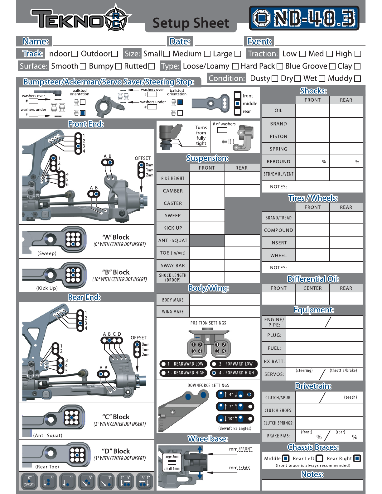
Box Stock
27
400 450
4x1.8 taper up 4x1.8 taper up
black
vent
5k 5k
15
60 40
2x green / 2x gold
aluminum
46
300oz min 300oz min
5k
vent
0 0
orange
29
-2
15 deg
0 deg
8.5 deg
2 deg
3 deg in.5 deg out
2.4
122
3
2
stock
stock
136.5
2.4
-2
4
0
4
3
3
0
Page 32

Tekno RC
10755 Scripps Poway Pkwy #598
San Diego CA 92131
USA
 Loading...