

Tekno SCT410.3, EB48SL Building Instructions


Introduction
Additional equipment and parts needed:
2 + channel radio transmitter and receiver
1/10th scale SC (4 pole) ESC and motor
High torque steering servo
2s LiPo battery
1/10th scale SC tires, wheels & CA glue
Short Course body and paint
MOD1 Pinion (TKR4171->TKR4190)
Tools needed:
Hex drivers (1.5mm, 2.0mm, 2.5mm)
Nut drivers (5.0mm, 5.5mm, 7.0mm, 8.0mm)
Hobby knife
Needle-nose pliers
Adjustable (Crescent) wrench (for shock assembly)
4mm turnbuckle wrench
Lexan Body Scissors
Disclaimer: Tekno RC is not responsible or liable for any property or personal damage, loss, or
injury incurred as a result of using this product. This kit is meant for use by persons 14 years of
age or older and in the strict connes of a legally permitted RC track or facility.
Warnings: Always double-check that your radio gear is working properly before operating vehicle.
Never operate the vehicle indoors (unless the RC track is an indoor facility). Use caution while
operating vehicle so as not to collide with people who may be turn mashalling or who might
otherwise not be aware that a fast moving RC vehicle is in the vicinity.
Warranty: We warrant that the parts included in this kit are free from defects. If you nd a
defective part in your kit, please contact us @ info@teknorc.com and we will help you to resolve
the issue. We do not warranty parts that may be broken during operation of the vehicle or
otherwise. Refer to the end of this instruction manual for a listing of spare/replacement and
option parts. All spare parts and other info are available on our website (www.teknorc.com)
and through our network of domestic and international dealers and distributors.
Thank you for purchasing the Tekno RC SCT410 .3 1/10th Scale Electric 4WD Competition Short
Course Truck. The SCT410.3 is an improved version of the already great SCT410. We are always
working on new projects, so please check our website (www.teknorc.com) regularly for the latest
news, parts, and kits. Thanks again.
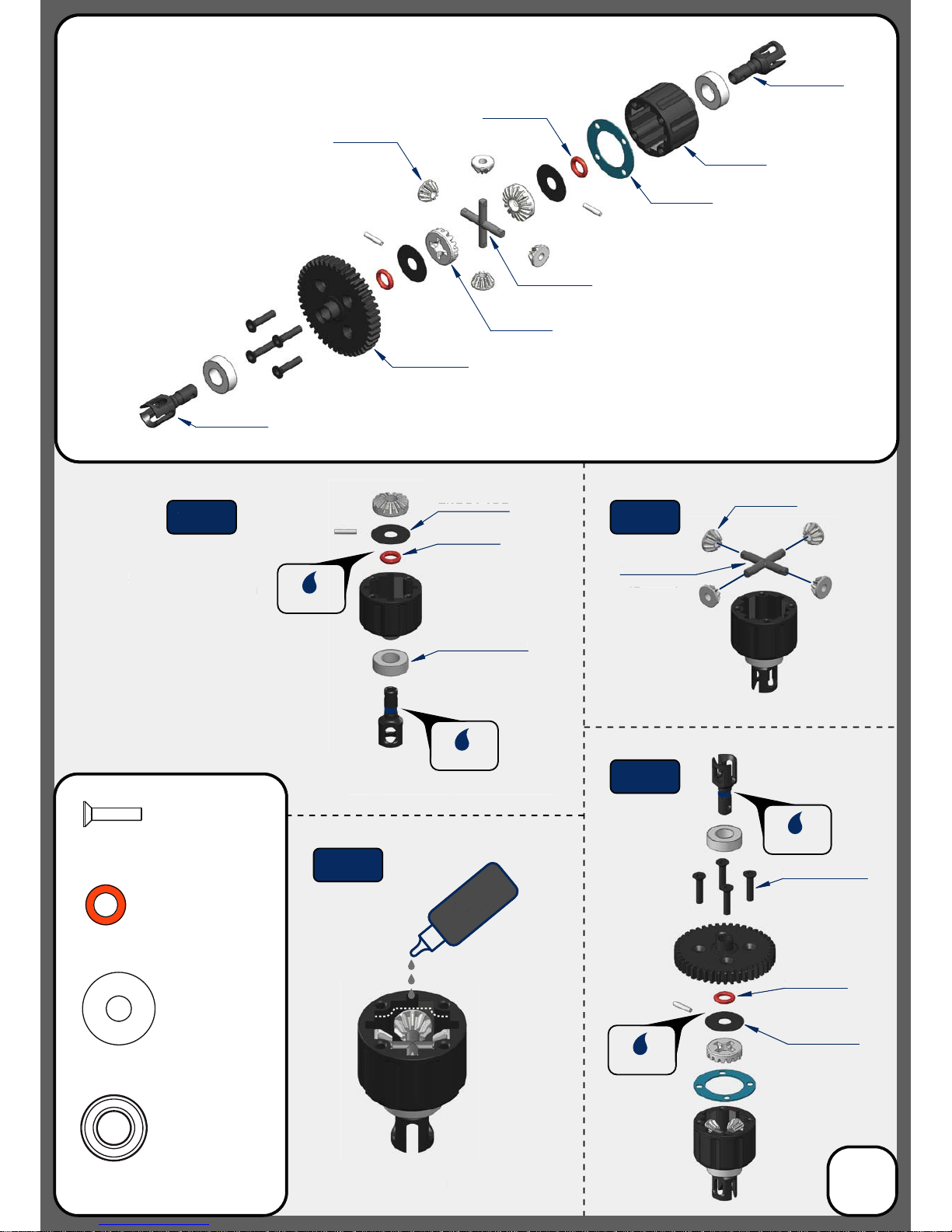
Apply grease to the groove
where the o-ring is placed
as well as the o-ring itself
Apply grease to the groove in the outdrive
Fill with 7000 wt oil to
1mm below full
DO NOT OVER FILL
TKR5145B
TKR5144
Bag A
Center Differential
(overview)
TKR5237K
TKR5149X
TKR5150
TKR5150
TKR5143
TKR5113
*TKR5237
*TKR5115
(Option)
*TKR5149A
(Option)
*TKR5149A
(Option)
TKR1325
M3x14mm Flat Head Screw
x4
TKR5144
TKR5145B
Step
A-1
TKRBB08165
Ball Bearing(8x16x5mm)
x2
TKR5144
Differential 0-rings
x2
TKR5145B
Differential Shims (6x17mm)
x2
TKR1325 x4
TKRBB08165
TKR5149X
Diff
Oil
Apply grease to the groov
e
w
here the o-ring is place
d
a
s well as the o-ring itsel
f
Apply grease to the groove in the outdriv
e
Fill with 7
000 wt o
il
to
mm below ful
l
O NOT OVER FIL
L
T
KR5145
B
T
KR51
44
TKR51
49A
(Option
)
R51
44
TK
R5145B
TK
A-
1
R1325 x
4
T
KRBB08165
T
KR5149
X
TKR5614X
TKR5614X
TKR5150
TKR5144
3
Grease
Grease
Grease
Grease
Step
A-2
Step
A-4
Step
A-3
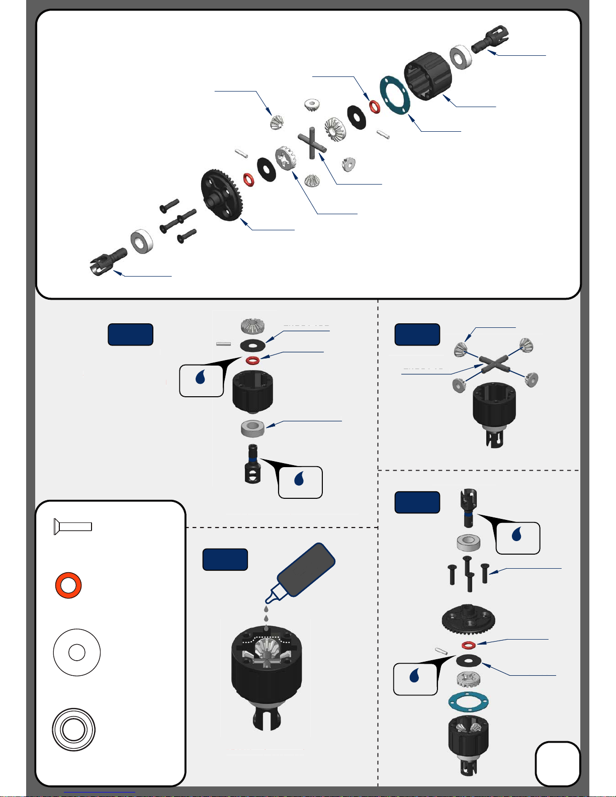
Apply grease to the groove
where the o-ring is placed
as well as the o-ring itself
Apply grease to the groove in the outdrive
Repeat for rear di
Fill FRONT with 7000 wt oil
Fill REAR with 5000 wt oil
to1mm below full
DO NOT OVER FILL
Repeat for rear di
Repeat for rear di
Repeat for rear di
TKR5145B
TKR5144
Bag B
Front and Rear Differential
(overview)
TKR5151
TKR5149X
TKR5150
TKR5150
TKR5143
TKR5113
TKR1325
M3x14mm Flat Head Screw
x8
TKR5144
TKR5145B
TKRBB08165
Ball Bearing(8x16x5mm)
x4
TKR5144
Differential 0-rings
x4
TKR5145B
Differential Shims (6x17mm)
x4
TKR1325 x4
TKRBB08165
TKR5149X
Diff
Oil
Apply grease to the groov
e
here the o-ring is place
d
s well as the o-ring itsel
f
Apply grease to the groove in the outdriv
e
Repeat for rear di
ill FRONT with 7
000 wt oil
Fill REAR with 5000 wt oi
l
to1mm below full
NOT OVER FILL
Repeat for rear di
Repeat for rear di
Repeat for rear di
T
KR5145
B
T
KR51
44
TKR51
44
TKR5145B
KR1325 x
4
T
KRBB08165
T
KR51
49
TKR5614X
TKR5614X
TKR5150
TKR5144
4
Grease
Grease
Grease
Grease
Step
B-2
Step
B-1
Step
B-4
Step
B-3
*TKR5149A
(Option)
*TKR5149A
(Option)
TKR1525
TKR5012
TKR5012
TKR5581
TKR5575X
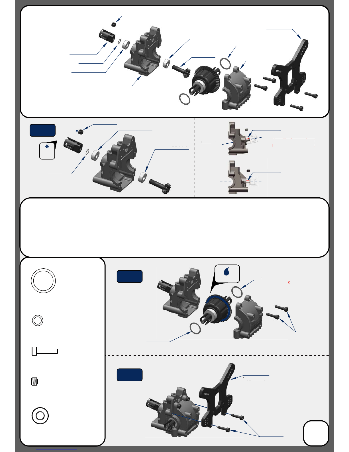
TKR5152
Front
Rear
Note: The front and rear
bulkheads are dierent.
The front has a much
greater output angle
compared to the rear.
TKR1603
TKRBB05114
TKRBB05114
TKR1226
TKR1222
TKR1222
TKR1525
TKR1222
TKR1226
TKRBB05114
TKR1525
M3x14mm Cap Head Screw
x4
TKRBB05114
Ball Bearing (5x11x4)
x2
TKR1603
M5x4mm Set Screw
x1
x2
TKR1222
13x16x0.1mm Diff shim
TKR1226
5x7x0.2mm shim
x1
TKR1603
Grease
Note: at spot
*
may not be needed
*
may not be needed
Note: at spot
*TKR5581C
(Option)
TKR5581
*TKR5581C
(Option)
TKRBB05114
TKR152
5
ront
Rea
r
Note: The front and rear
lkh
eads are dierent.
The front has a muc
h
reater output angle
compared to the rear.
TKRBB0511
511
4
T
KRBB
0
T
KR122
6
TKR1222
TKR152
5
TKR160
3
r
ease
p
t spo
t
ote:
a
may not be neede
d
ay not be needed
p
at spo
t
ote:
T
KR558
1
TKR5581
C
Option
)
Bag C
Front Gearbox
(overview)
5
Thread
Lock
Note: TKR1222 and TKR1226 Shims - The gear mesh should be tight without any binding. TKR1226 should
always be installed. Then test tment of the di with both TKR1222 shims on the gear-side of the di. If the di
turns freely without binding, continue to next step. If the di binds and does not turn freely (it will make a
grinding or crunching sound when spun), remove one TKR1222 shim from the gear side and install it onto the
other side of the di. Reassemble and test the mesh again. If it is still binding, remove the second TKR1222 shim
from the gear side and install it onto the other side of the di. When you are satised that you have the best
gear mesh possible continue to the next step. You may end up using only one shim on the gear side.
Step
C-1
Step
C-2
Step
C-3
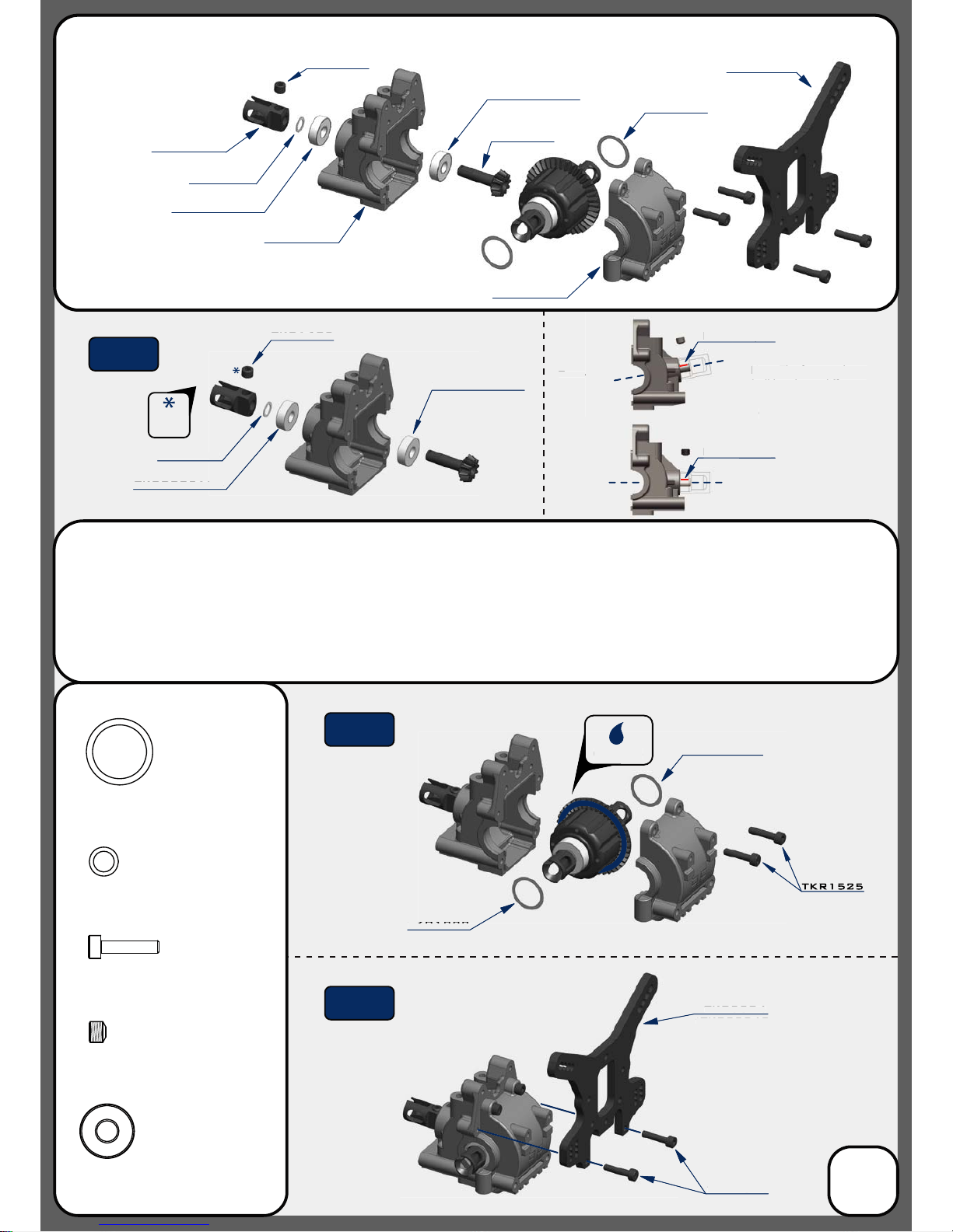
TKR5575X
TKR5016B
TKR5152
TKR5016B
TKR5584
TKR1222
TKR1222
TKR1525
TKR1222
TKR1525
M3x14mm Cap Head Screw
x4
TKRBB05134
Ball Bearing (5x13x4)
x2
TKR1603
M5x4mm Set Screw
x1
TKR1222
13x16x0.1mm Diff Shim
x2
TKR1226
5x7x0.2mm Shim
x1
TKR1603
TKRBB05134
TKRBB05134
TKRBB05134
TKR1226
TKRBB05134
TKR1603
TKR1525TKR1525
Grease
Front
Rear
Note: at spot
Note: at spot
*TKR5584C
(Option)
TKR5584
*TKR5584C
(Option)
Note: The front and rear
bulkheads are dierent.
The front has a much
greater output angle
compared to the rear.
TKR1226
TKR1222
T
KR1525
TKR160
3
T
KRBB051
3
513
4
TKR
TKR12
2
TKR152
5
TKR1525
r
ease
Fro
n
ea
r
p
t spo
t
Note:
a
T
KR558
4
*TKR5584C
Option)
The front and r
ear
lkh
eads are dierent.
T
he front has a muc
h
greater output ang
le
ompared to the rear.
Bag D
Rear Gearbox
(overview)
6
Thread
Lock
Note: TKR1222 and TKR1226 Shims - The gear mesh should be tight without any binding. TKR1226 should
always be installed. Then test tment of the di with both TKR1222 shims on the gear-side of the di. If the di
turns freely without binding, continue to next step. If the di binds and does not turn freely (it will make a
grinding or crunching sound when spun), remove one TKR1222 shim from the gear side and install it onto the
other side of the di. Reassemble and test the mesh again. If it is still binding, remove the second TKR1222 shim
from the gear side and install it onto the other side of the di. When you are satised that you have the best
gear mesh possible continue to the next step. You may end up using only one shim on the gear side.
*
may not be needed
*
may not be needed
Step
D-1
Step
D-2
Step
D-3
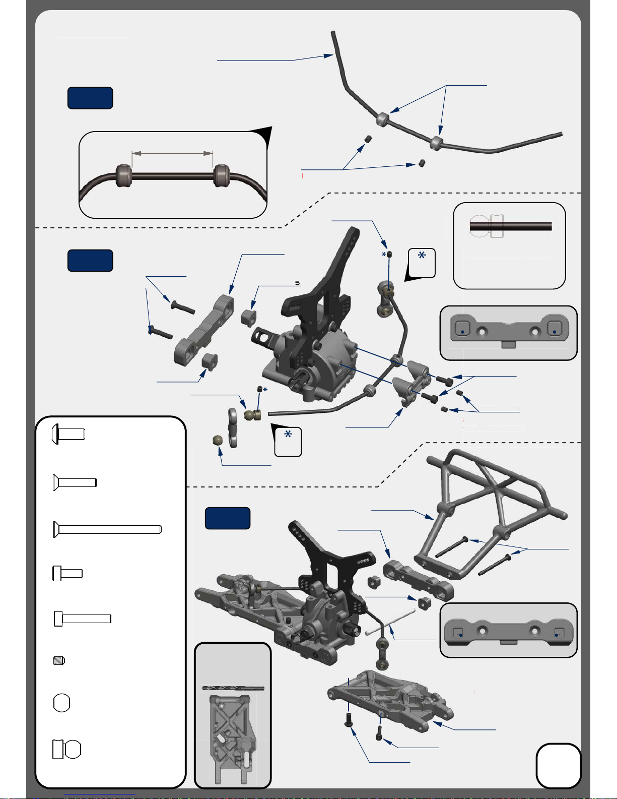
Stock Position
(”D” Block)
Stock Position
(”C” Block)
30.2
TKR1601
TKR1601
TKR1601
TKR5086
TKR5491 - 2.4mm
TKR5086
Install the Sway Bar Ball onto the
Sway Bar Wire until the end of
the wire is ush with the ball as
picture above.
Note: Loosen the M3x4 set screw (TKR1601)
if
the anti-roll bar does not
turn freely.
Note: With these stock settings,
Anti-Squat is: 3° / Rear Toe is: 2°
For reference: With center dot
inserts in both braces,
Anti-Squat = 3° / Rear Toe = 3°
Note: Do not over-tighten
TKR5049A
TKR5165
TKR5730
TKR5165
TKR5730
TKR5799
TKR5515
TKR5079A
TKR5165
TKR1522
TKR1522
M3x8mm Cap Head Screw
Bag E
Rear End
*TKR5490 - 2.3mm
*TKR5492 - 2.5mm
*TKR5493 - 2.6mm
*TKR5494 - 2.8mm
*TKR5495 - 3.0mm
(Option)
(Option)
*TKR5163
(Option)
*TKR5164
30.2
TKR160
1
TKR5086
TKR5491 - 2.4m
m
TKR5086
nstall the Sway Bar Ball onto t
he
way Bar Wire until the end of
he wire is
us
h with the ball
as
icture above
.
en the M3x4 set screw (TKR1601
)
ote: Loo
s
if
i-roll bar
does not
he
an
urn freely.
Note: With these stock settings,
Anti-Squat is: 3° / Rear Toe is: 2°
r r
eference:
With center
dot
inserts in both braces
,
Anti-Squat = 3° / Rear Toe = 3°
ote: Do not over-tighten
TKR5049A
TKR5165
TKR5730
TK
T
KR5730
TKR5799
KR5515
TKR5079A
TKR516
5
TKR1522
Rear End
*TKR5490 - 2.3mm
*TKR5492 - 2.5mm
*TKR5493 - 2.6mm
*TKR5
494
- 2.8mm
*TKR5495 - 3.0mm
Option
)
Option
)
*TKR51
63
Option
)
TKR5164
Thread
Lock
Thread
Lock
7
TKR1327
TKR1333
M3x40mm Flat Head Screw
x2
TKR1238
M4x10mm Droop Screw
x2
TKR5049A
Pivot Ball Sway Bar
x2
x6
TKR5079A
Stabilizer Ball
x2
TKR1528
M3x18mm Cap Head Screw
x2
x2
TKR1327
M3x16mm Flat Head Screw
x2
TKR1333TKR1333
TKR1238
TKR1528
tock Positi
”D” Bloc
k)
Position
Block
)
TKR1601
M3x4mm Set Screw
Step
E-1
Step
E-2
Step
E-3
TKR5020
Use a #19 drill bit or
4mm reamer to ream
arms until hinge pin
falls through freely.
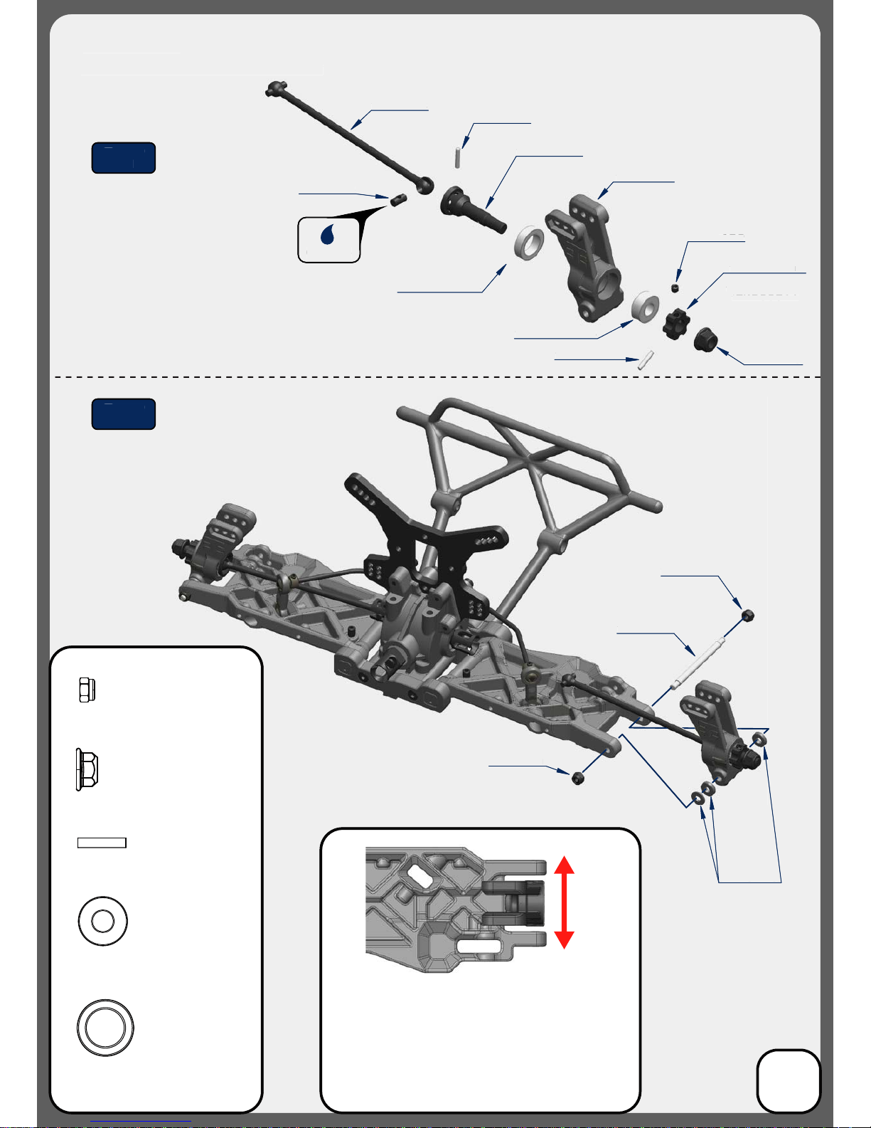
TKR5572
TKR6856
TKR5570B
TKR5545
TKRBB10154
TKRBB06135
TKR6856
TKR5571M
TKR5534
TKR5165
TKR1201
TKR1201
Changes to the wheelbase have a dramatic eect on handling,
since it shifts the disribution of weight over the rear wheels.
This adjusts traction. By shortening the wheelbase at the rear, you
are placing more weight over the rear wheels.
Changes to the wheelbase also change the amount of sweep the
rear driveshaft will have. More driveshaft sweep creates an eect
similar to anti-squat, where the rear end gets pushed upwards on
throttle. This helps reduce chassis slap landing jumps on throttle.
TKR1609
TKR6856
TKR1215
TKR6856
CV Joint Pin
x4
TKR1201
M3 Locknut Black
x4
TKRBB10154
Ball Bearing (10x15x4)
x2
TKRBB06135
Ball Bearing (6x13x5)
x2
*TKR5571
*TKR5571-17
*TKR5571A
*TKR1654X
(Option)
Grease
TKR1215
M4 Lock Nut Flange Black
x2
(FRONT)
(REAR)
Step
F-1
Step
F-2
Bag F
Rear Hub/CVA Assembly
T
KR685
6
TKR5570B
KR5545
T
KRBB1015
4
T
KRBB0613
5
TKR68
56
T
KR55
71M
TKR55
34
KR51
65
KR120
1
TKR120
1
60
9
TK
TKR68
56
TKR121
5
*TKR557
1
TKR5571-1
7
*TKR55
71A
*TKR1654X
Option
)
r
ease
F-
1tep
-
Rear Hub/CVA Assembl
y
8
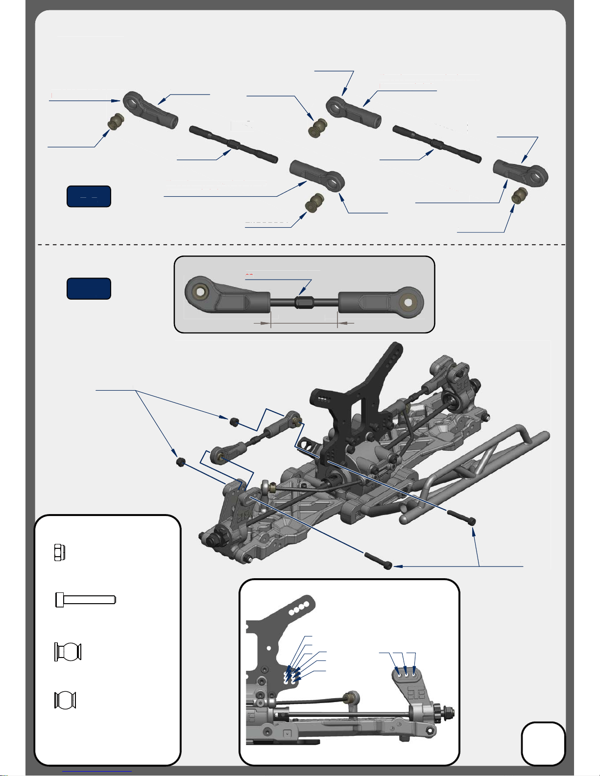
TKR5188
TKR5123
TKR5188
TKR5052A
This side mounts on hub
Note: angled link
This side mounts on shock tower
Note: straight link
TKR5053A
25.50
Note: Notch always goes
on
left side of vehicle
1
2
3
4
5
6
A
B
C
Stock position is 6/B
TKR1529
TKR1201
Right
TKR5053A
This side mounts on hub
Note: angled link
This side mounts on shock tower
Note: straight link
TKR5188
Left
TKR5123
TKR1201
M3 Locknut Black
x4
TKR1529
M3x20mm Cap Head Screw
x4
TKR5053A
Pivot Ball M3x6.8mm
No Flange
x2
TKR5052A
Pivot Ball M3x6.8mm
x2
TKR5188
TKR5052A
Step
F-3
Step
F-4
Bag F
Rear Camber Links
TKR518
8
T
KR5123
TKR5188
TKR5052A
This side mounts o
n h
ub
Note: angled lin
k
This side mounts on
Note: straight lin
k
TKR5053
A
25.50
ote: Notch always goes
t s
of
ve
hic
le
T
KR152
TKR505
3A
This side moun
mounts on hub
ote: angled link
Th
is side mounts on shock towe
r
Note: straight link
KR5188
TKR51
23
TKR5188
TKR5052
A
-
3
Step
-
4
Rear Camber Link
s
9
 Loading...