

Page 1
Page 2
Introduction
Additional equipment and parts needed:
•
2 Channel radio and receiver
•
1/10th scale ESC and motor system
•
Low prole or standard size high torque steering servo (at least 150 oz/in)
* Running less than the recommended rating will increase the chance of premature servo failure.
•
2S (2 cell, 7.4v) shorty LiPo battery
•
Paint for body
•
1/10th scale 4x4 buggy wheels & tires, CA glue (or premounts)
•
48 pitch pinion 15 tooth - 30 tooth
Tools needed:
•
Hex drivers 1.5mm (TKR1104), 2.0mm (TKR1105), 2.5mm (TKR1106)
•
Nut drivers 5.5mm (TKR1108), 7.0mm (TKR1109)
•
Hobby knife
•
Needle-nose pliers
•
Shock tool (TKR1115) OR adjustable (Crescent) wrench (for shock assembly)
•
4mm turnbuckle wrench (TKR1103)
•
5.5/7.0 two sided wrench (TKR1119)
Disclaimer: Tekno RC is not responsible or liable for any property or personal damage, loss, or injury incurred as a
result of using this product. This kit is meant for use by persons 14 years of age or older and in the strict connes of
a legally permitted RC track or facility.
Warnings: Always double-check that your radio gear is working properly before operating vehicle. Never operate the
vehicle indoors (unless the RC track is an indoor facility). Use caution while operating vehicle so as not to collide with
people who may be turn marshalling or who might otherwise not be aware that a fast moving RC vehicle is in the vicinity.
Warranty: We warrant that the parts included in this kit are free from defects. If you nd a defective part in your kit,
please contact us @ [email protected] and we will help you to resolve the issue. We do not warranty parts that may be
broken during operation of the vehicle or otherwise. Refer to the end of this instruction manual for a listing of
spare/replacement and option parts. All spare parts and other info are available on our website (www.teknorc.com)
and through our network of domestic and international dealers and distributors.
Thank you for purchasing the Tekno RC EB410 1/10th Scale 4WD Competition Electric buggy kit.
We are always working on new projects, so please REGULARLY check our website
at www.teknorc.com or our Facebook page at www.facebook.com/teknorc
for the latest news, parts, and kits.
Take your time! When you work your way through these building instructions, keep an eye out
for the following important indicators below:
•
RED TEXT - This indicates important areas of the build process that should be observed.
•
YOUTUBE - We also have many useful build videos on Youtube, so be sure to check these out!
https://www.youtube.com/c/teknorc
Thread Lock icons
Thread lock is always used when a screw is inserted into any metal part. (Included with kit)
Thread
Lock
Grease icons
Grease is usually used on areas with movement and for sealing. (Included with kit)
Grease
Page 3
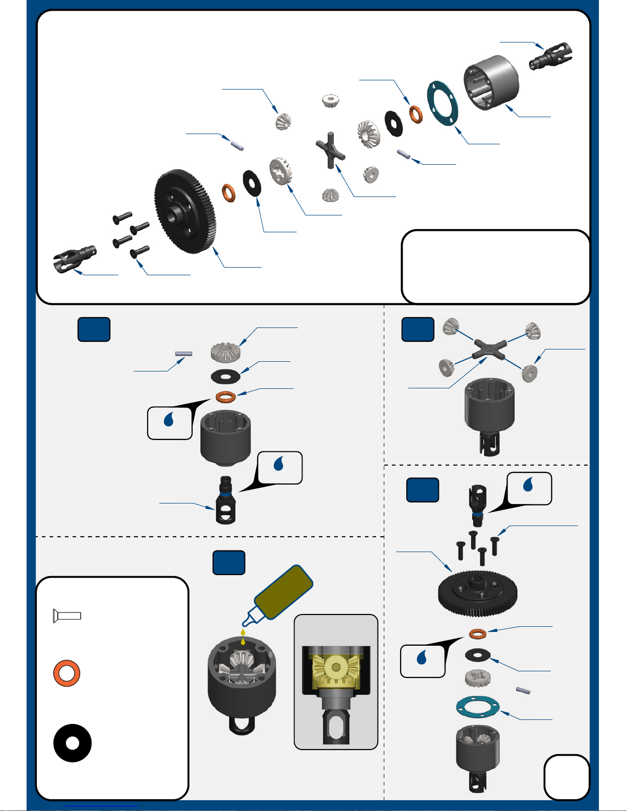
TKR6517
TKR5144
Bag A
Center Dierential
(overview)
TKR6522
TKR6513X
TKR6550
TKR6550
TKR6515
TKR6511
*TKR6670
(Option)
TKR5144
TKR6517
TKR6515
Step
A-2
Step
A-4
Fill Level
Step
A-3
Step
A-1
TKR5144
Dierential 0-rings
x2
TKR6517
Dierential Shims (5x14mm)
x2
TKR1303
M2.5x10mm Flat Head Screw
x4
TKR1303 x4
TKR6550
TKR6513X
Di
Oil
TKR6522
*TKR6670
(Option)
TKR6514
TKR6514
TKR6514
TKR6514
TKR6517
TKR6550
TKR5144
TKR1303 x4
3
Grease
Grease
Grease
Grease
Fill with #15,000 oil to
1mm below full
DO NOT OVER FILL
Note: Apply grease to the
groove in the outdrive.
Note: These screws
only need to be snug.
Do not over-tighten
or the internal gears
will bind up.
Note: Apply grease to the
groove where the o-ring is
placed as well as the o-ring itself.
TKR6514
TKR6514
Note: Gears will feel a bit tight at first. Please
run 3-4 packs on the track for break-in
before evaluating the internal gear mesh.
Once broken in, it is advised to rebuild each di
with fresh oil. Once complete, the dis will be
smooth and race ready.
Page 4
Bag B
Front and Rear Dierential
(overview)
TKR6512
TKR6513X
TKR6550
TKR6515
TKR6511
TKR5144
TKR6517
TKR1303 x4
TKR6514
TKR6514
TKR6515
TKR5144
TKR1303 x4
4
Grease
Step
B-1
Step
B-2
Repeat for rear di
Fill Level
Di
Oil
Step
B-3
Step
B-4
Repeat for rear di
TKR5144
Dierential 0-rings
x4
TKR6517
Dierential Shims (5x14mm)
x4
TKR1303
M2.5x10mm Flat Head Screw
x8
Grease
TKR6513X
Repeat for rear di
Fill FRONT with #15,000 oil
Fill REAR with #7,000 oil
to 1mm below full
DO NOT OVER FILL
Repeat for rear di
TKR6517
TKR5144
Grease
Grease
TKR6550
TKR6514
TKR6514
TKR6512
TKR6514
TKR6514
Note: Apply grease to the
groove in the outdrive.
Note: Gears will feel a bit tight at first. Please
run 3-4 packs on the track for break-in
before evaluating the internal gear mesh.
Once broken in, it is advised to rebuild each di
with fresh oil. Once complete, the dis will be
smooth and race ready.
Note: Apply grease to the
groove where the o-ring is
placed as well as the o-ring itself.
TKR6550
TKR6517
TKR6550
Page 5
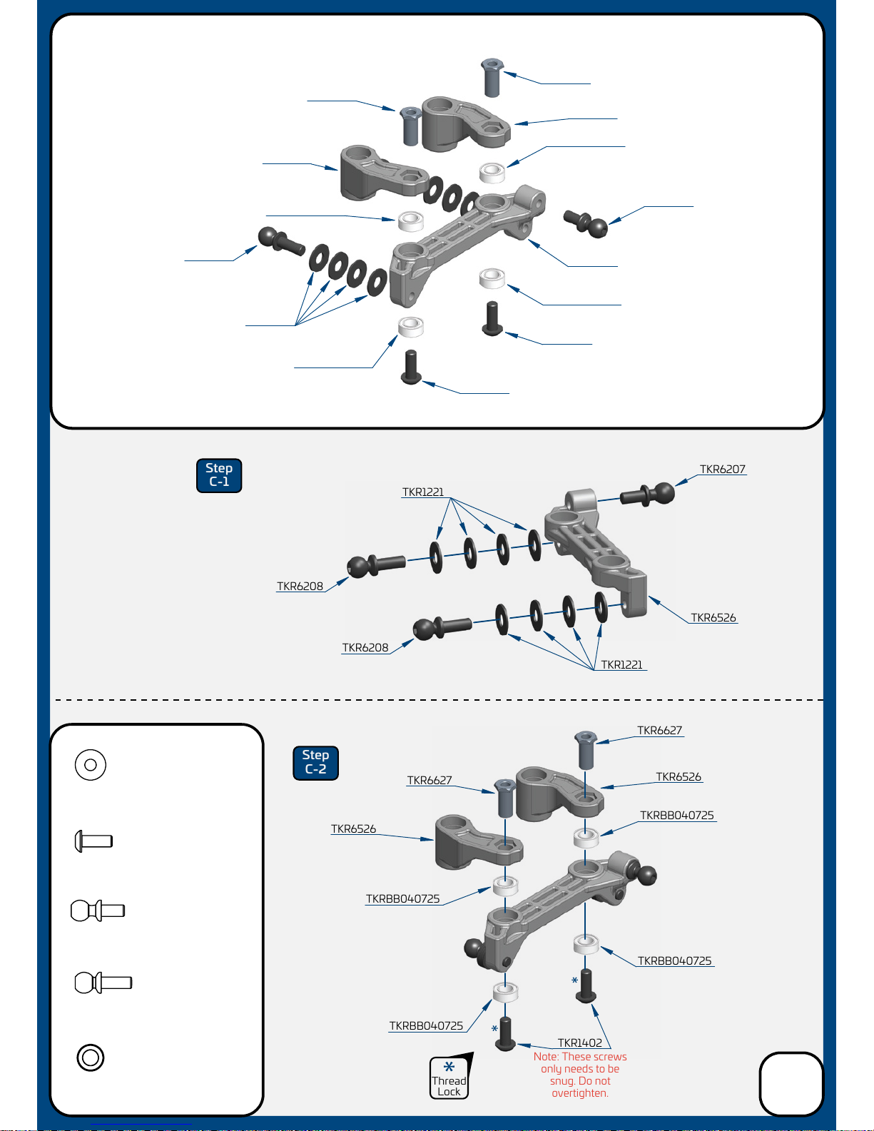
TKR1221
TKR1221
TKR1221
TKR6627
TKR6627
TKR6627
TKR6627
TKR1402
TKR1402
TKR1402
TKR6526
TKR6526
TKR6207
TKR6207
TKR1221
M3x8mm Washer
x8
TKRBB040725
TKRBB040725
TKR6526
TKR6208
TKR6208
TKR6208
TKRBB040725
TKRBB040725
TKRBB040725
TKRBB040725
TKRBB040725
TKRBB040725
TKR6526
TKR6526
TKR6526
Step
C-1
Step
C-2
TKRBB040725
Ball Bearing (4x7x2.5)
x4
Thread
Lock
TKR6207
M3x6mm Ball Stud
x1
TKR6208
M3x8mm Ball Stud
x2
TKR1402
M3x8mm Button Head Screw
x2
Note: These screws
only needs to be
snug. Do not
overtighten.
Bag C
Steering Assembly
(overview)
5
Page 6
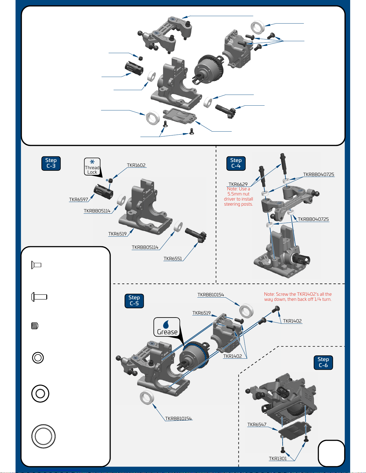
TKR1301
TKRBB10154
TKRBB10154
TKR1602
TKRBB10154
TKRBB10154
TKR1301
TKRBB05114
TKR6629
TKR6551
TKRBB05114
TKRBB05114
TKRBB05114
TKR6551
TKR6547
TKR6519
TKR6597
TKR6547
TKRBB05114
Ball Bearing (5x11x4)
x2
TKR1602
TKR6597
(assembly from previous page)
Step
C-3
Step
C-4
Step
C-5
Step
C-6
TKR1301
M2.5x6mm Flat Head Screw
x2
TKR1402
M3x8mm Button Head Screw
x4
TKR1602
M4x4mm Set Screw
x1
TKRBB10154
Ball Bearing (10x15x4)
x2
TKRBB040725
Ball Bearing (4x7x2.5)
x4
TKRBB040725
TKRBB040725
TKR1402
Thread
Lock
Grease
TKR6519
TKR1402
TKR1402
Note: Use a
5.5mm nut
driver to install
steering posts.
Note: Screw the TKR1402’s all the
way down, then back o 1/4 turn.
Bag C
Front Bulkhead Assembly
(overview)
6
Page 7
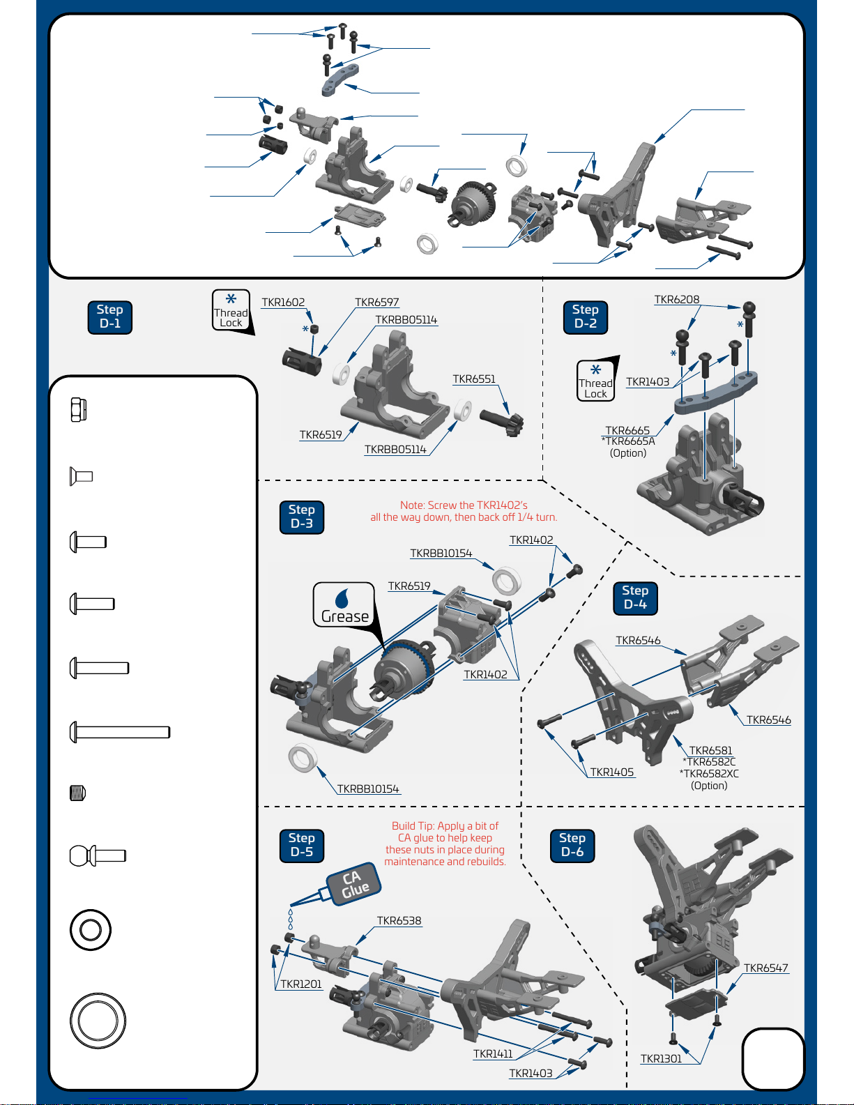
Step
D-1
Step
D-2
Step
D-3
Step
D-4
Step
D-5
Step
D-6
TKRBB05114
Ball Bearing (5x11x4)
x2
TKR1201
M3 Locknut Black
x2
TKR1301
M2.5x6mm Flat Head Screw
x2
TKR1402
M3x8mm Button Head Screw
x4
TKR1403
M3x10mm Button Head Screw
x4
TKR1405
M3x14mm Button Head Screw
x2
TKR1411
M3x25mm Button Head Screw
x2
TKR1602
M4x4mm Set Screw
x1
TKRBB10154
Ball Bearing (10x15x4)
x2
TKR6208
M3x8mm Ball Stud
x2
CA
Glue
Bag D
Rear Bulkhead/
Wing Mount
Assembly
(overview)
Thread
Lock
Thread
Lock
TKR6208
TKR6538
TKR6519
TKR6581
TKR6546
TKR1201
TKR1602
TKR6597
TKR1403
TKR1411
TKR6547
TKRBB05114
TKR6551
TKRBB05114
TKR6597
TKR1602
TKRBB05114
TKR6551
TKR6665
TKR6665
TKR1405
TKR6208
TKR1403
TKR1403
TKR6519
TKR6519
TKRBB10154
TKRBB10154
TKR1402
TKR6581
TKR6547
TKR6546
TKR6538
TKR6546
TKR1403
TKR1405
TKRBB10154
TKR1301
TKR1301
TKR1411
TKR1402
4pcs
Grease
TKR1402
*TKR6582C
*TKR6582XC
(Option)
*TKR6582C
*TKR6582XC
(Option)
*TKR6665A
(Option)
TKR1201
Build Tip: Apply a bit of
CA glue to help keep
these nuts in place during
maintenance and rebuilds.
Note: Screw the TKR1402’s
all the way down, then back o 1/4 turn.
7
Page 8
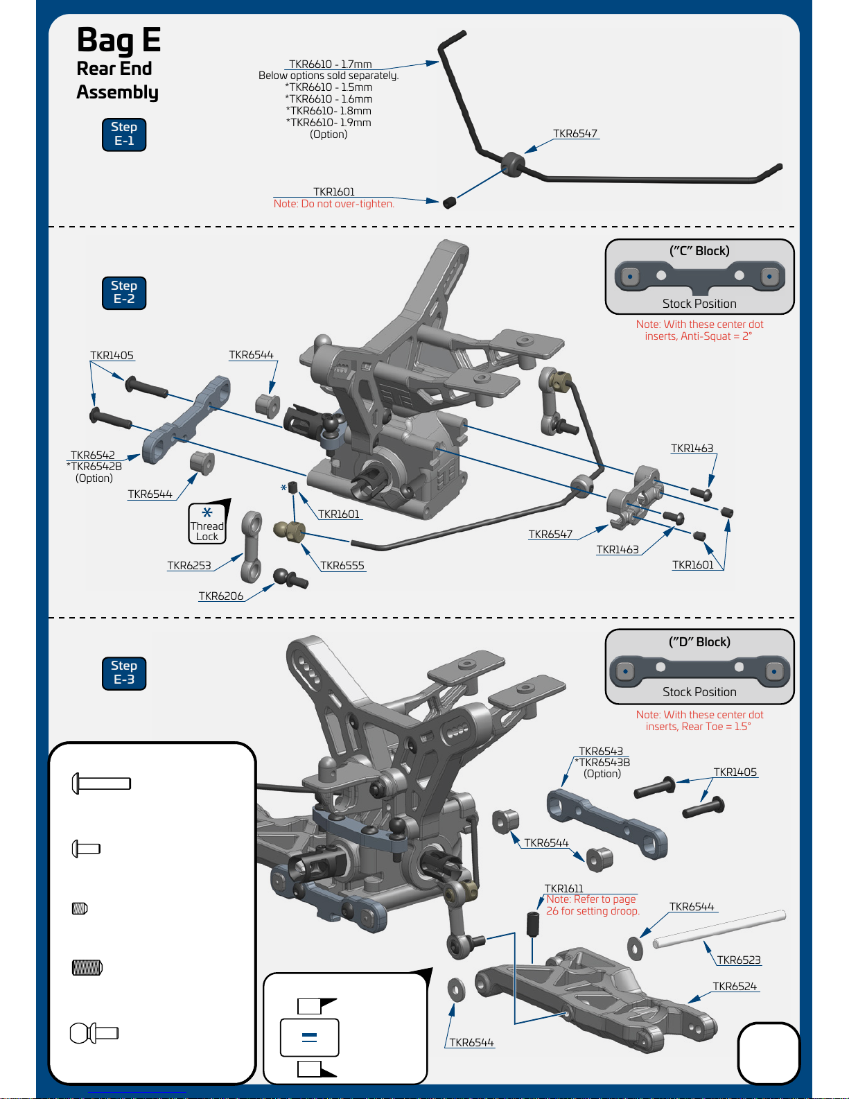
Stock Position
(”D” Block)
Stock Position
(”C” Block)
TKR1601
TKR6524
TKR6610 - 1.7mm
TKR6547
Note: With these center dot
inserts, Rear Toe = 1.5°
Note: Refer to page
26 for setting droop.
Note: With these center dot
inserts, Anti-Squat = 2°
Note: Do not over-tighten.
TKR6544
TKR6544
TKR6547
TKR6542
TKR1601
TKR6544
TKR1463
TKR6544
TKR6544
Bag E
Rear End
Assembly
Below options sold separately.
*TKR6610 - 1.5mm
*TKR6610 - 1.6mm
*TKR6610- 1.8mm
*TKR6610- 1.9mm
(Option)
*TKR6542B
(Option)
*TKR6543B
(Option)
Thread
Lock
TKR1405
TKR1405
TKR6523
TKR6543
TKR1601
TKR6555
TKR6206
TKR6253
TKR1611
x5
TKR1601
M3x4mm Set Screw
Step
E-1
Step
E-2
Step
E-3
TKR1405
M3x14mm Button Head Screw
x4
TKR1463
M2.5x6mm Button Head Screw
x2
TKR1611
M4x8mm Set Screw
x2
TKR6206
M3x6mm Ball Stud
x2
TKR1463
8
large shim
goes towards
the front
Wheelbase Shims
1
.5
large 1mm
front
rear
small .5mm
Page 9
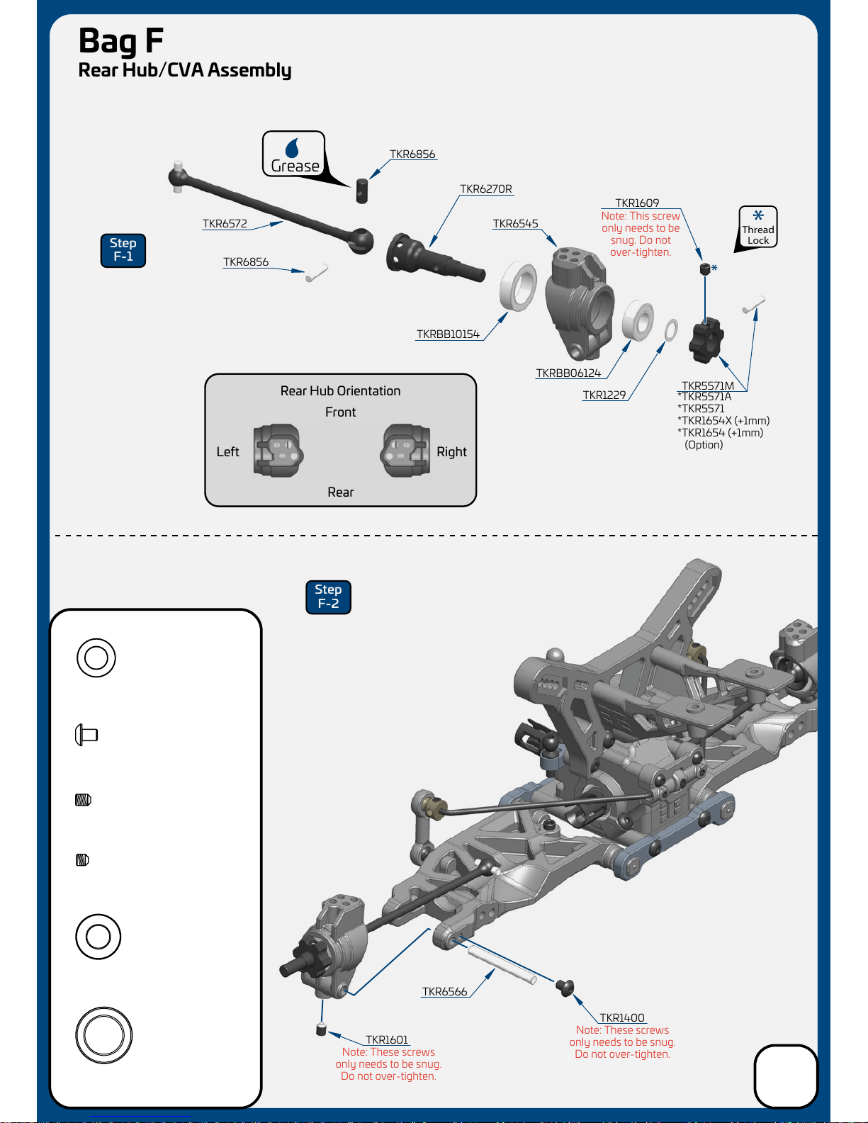
TKR6856
TKR6856
TKR6270R
TKR6545
TKRBB10154
TKRBB06124
TKR5571M
TKR1609
TKR1229
TKR6572
TKRBB10154
Ball Bearing (10x15x4)
x2
*TKR5571A
*TKR5571
*TKR1654X (+1mm)
*TKR1654 (+1mm)
(Option)
Note: This screw
only needs to be
snug. Do not
over-tighten.
TKR1229
6x10x0.2mm Shim
x2
x2
TKR1601
M3x4mm Set Screw
TKR1609
M3x3mm Set Screw
x2
Step
F-1
Step
F-2
TKRBB06124
Ball Bearing (6x12x4)
x2
Grease
TKR1400
M3x4mm Button Head Screw
x2
Thread
Lock
TKR1601
TKR1400
TKR6566
Note: These screws
only needs to be snug.
Do not over-tighten.
Note: These screws
only needs to be snug.
Do not over-tighten.
Rear Hub Orientation
RightLeft
Rear
Front
Bag F
Rear Hub/CVA Assembly
9
Page 10
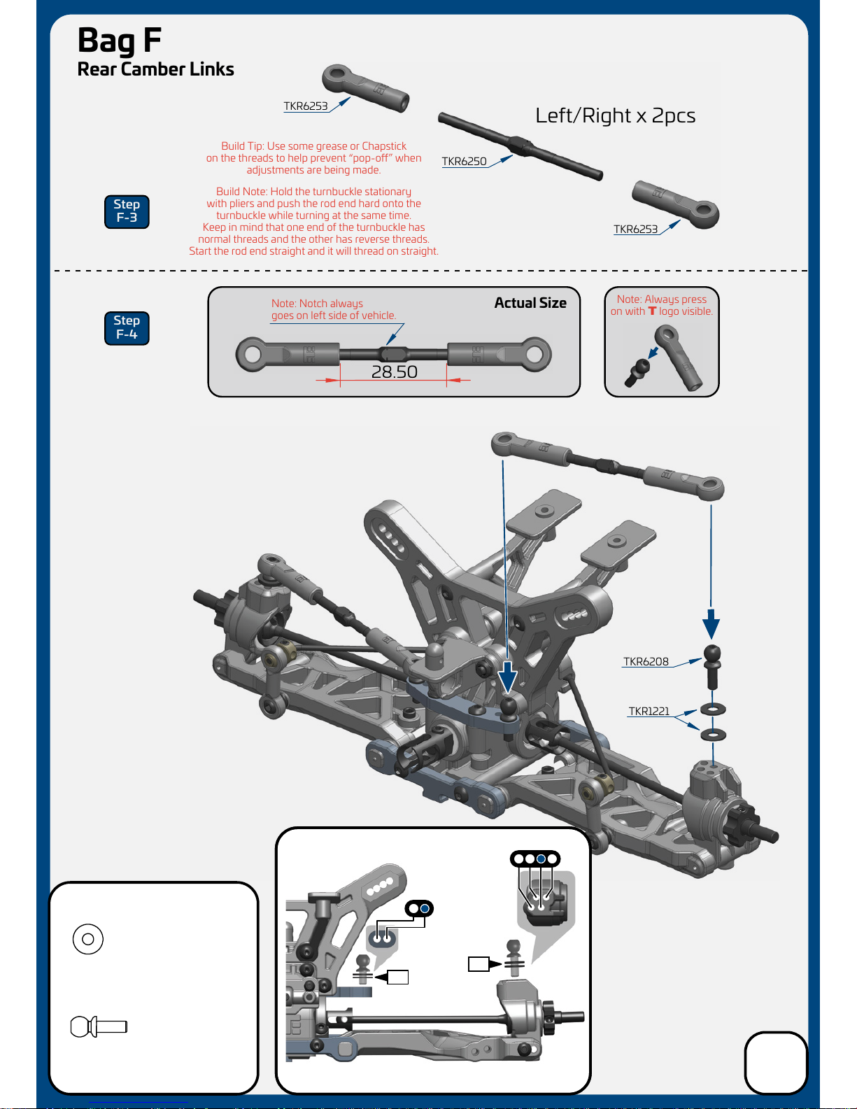
TKR6250
TKR6253
28.50
Note: Notch always
goes on
left side of vehicle.
Note: Always press
on with T logo visible.
Stock position is 2/C
0
2
Actual Size
Left/Right x 2pcs
TKR6253
TKR6208
TKR1221
Step
F-3
Step
F-4
DCBA
1 2
WASHERS
WASHERS
TKR1221
M3x8mm Washer
x4
TKR6208
M3x8mm Ball Stud
x2
Build Note: Hold the turnbuckle stationary
with pliers and push the rod end hard onto the
turnbuckle while turning at the same time.
Keep in mind that one end of the turnbuckle has
normal threads and the other has reverse threads.
Start the rod end straight and it will thread on straight.
Build Tip: Use some grease or Chapstick
on the threads to help prevent “pop-o” when
adjustments are being made.
Bag F
Rear Camber Links
10
Page 11
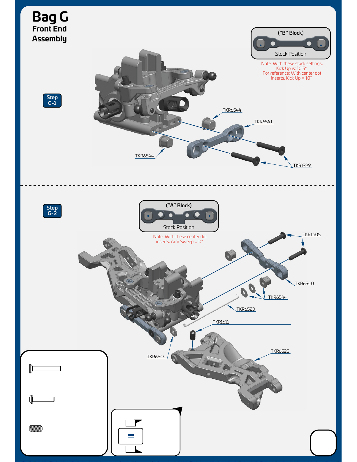
Stock Position
(”B” Block)
Stock Position
(”A” Block)
TKR1329
Bag G
Front End
Assembly
TKR1405
Note: With these center dot
inserts, Arm Sweep = 0°
Note: With these stock settings,
Kick Up is: 10.5°
For reference: With center dot
inserts, Kick Up = 10°
Step
G-1
Step
G-2
TKR1405
M3x14mm Button Head Screw
x2
TKR1611
M4x8mm Set Screw
x2
TKR6523
TKR6540
TKR6541
TKR6544
TKR1611
TKR6525
TKR6544
TKR6544
TKR6544
TKR1329
M3x20mm Flat Head Screw
x2
11
large shim
goes towards
the rear
Wheelbase Shims
1
1
large 1mm
front
rear
small .5mm
Note: Refer to page 26 for setting droop.
Page 12
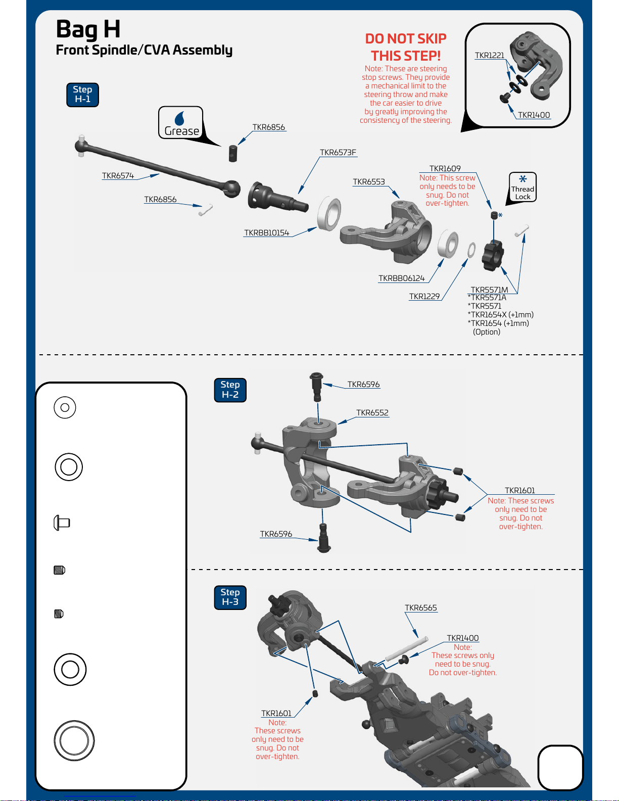
TKR1601
TKR6565
Bag H
Front Spindle/CVA Assembly
DO NOT SKIP
THIS STEP!
TKR1400
Step
H-1
Step
H-2
Step
H-3
TKR6856
TKR6856
TKR6573F
TKR6553
TKRBB10154
TKRBB06124
TKR5571M
TKR1609
TKR1229
TKR6596
TKR6596
TKR6574
TKR6552
TKR1601
Grease
Note: This screw
only needs to be
snug. Do not
over-tighten.
Note: These are steering
stop screws. They provide
a mechanical limit to the
steering throw and make
the car easier to drive
by greatly improving the
consistency of the steering.
Note: These screws
only need to be
snug. Do not
over-tighten.
Note:
These screws
only need to be
snug. Do not
over-tighten.
Note:
These screws only
need to be snug.
Do not over-tighten.
TKRBB10154
Ball Bearing (10x15x4)
x2
x5
TKR1601
M3x4mm Set Screw
TKR1609
M3x3mm Set Screw
x7
TKRBB06124
Ball Bearing (6x12x4)
x2
TKR1400
M3x4mm Button Head Screw
x4
TKR1221
TKR1400
Thread
Lock
TKR1229
6x10x0.2mm Shim
x2
TKR1221
M3x8mm Washer
x4
*TKR5571A
*TKR5571
*TKR1654X (+1mm)
*TKR1654 (+1mm)
(Option)
12
Page 13
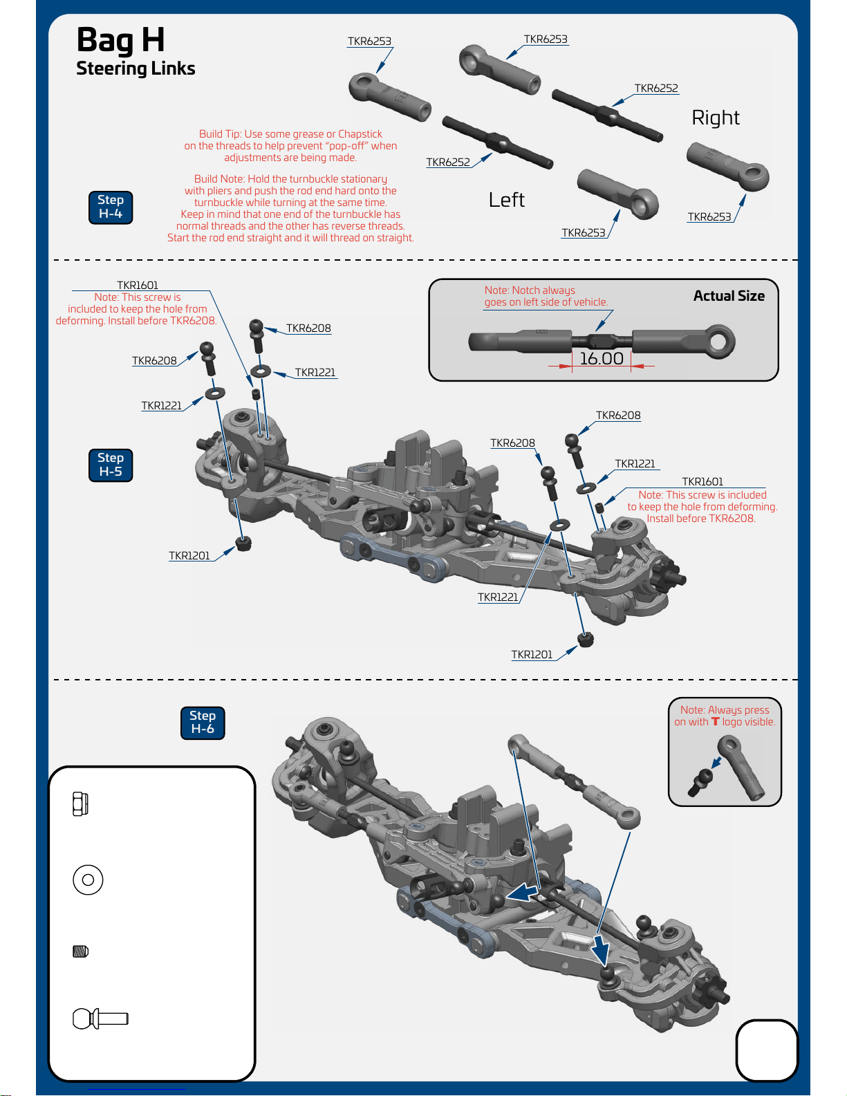
16.00
TKR1201
M3 Lock Nut Black
x2
TKR6252
TKR6253
Right
Left
TKR6253
TKR6253
TKR6208
TKR1221
TKR1221
TKR1201
TKR1201
TKR1601
TKR6208
TKR6252
TKR6253
TKR1601
TKR6208
TKR1221
TKR1221
TKR6208
TKR1221
M3x8mm Washer
x4
Note: Notch always
goes on
left side of vehicle.
Note: This screw is included
to keep the hole from deforming.
Install before TKR6208.
Note: This screw is
included to keep the hole from
deforming. Install before TKR6208.
Bag H
Steering Links
Step
H-4
Step
H-5
Step
H-6
TKR6208
M3x8mm Ball Stud
x4
x2
TKR1601
M3x4mm Set Screw
Actual Size
Note: Always press
on with T logo visible.
Build Note: Hold the turnbuckle stationary
with pliers and push the rod end hard onto the
turnbuckle while turning at the same time.
Keep in mind that one end of the turnbuckle has
normal threads and the other has reverse threads.
Start the rod end straight and it will thread on straight.
Build Tip: Use some grease or Chapstick
on the threads to help prevent “pop-o” when
adjustments are being made.
13
Page 14
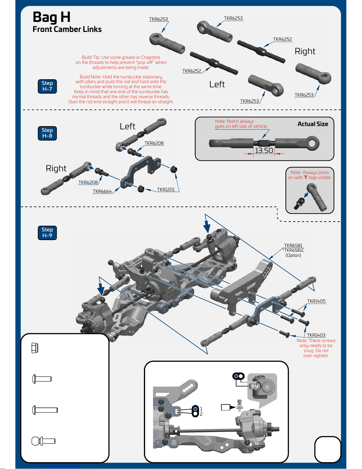
A
B
WASHERS
Stock position is 1/A
13.50
TKR1201
M3 Lock Nut Black
x2
Note: Notch always
goes on
left side of vehicle.
Bag H
Front Camber Links
Step
H-7
Step
H-8
Step
H-9
Right
Left
TKR6252
TKR6253
Right
Left
TKR6253
TKR6208
TKR6664
TKR6252
TKR6253
TKR6208
TKR1201
TKR1403
TKR1405
TKR1403
M3x10mm Button Head Screw
x2
TKR1405
M3x14mm Button Head Screw
x2
TKR1405
M3x14mm Button Head Screw
x2
TKR6208
M3x8mm Ball Stud
x2
1
TKR6581
Note: These screws
only needs to be
snug. Do not
over-tighten.
Actual Size
*TKR6581C
(Option)
TKR6253
Note: Always press
on with T logo visible.
Build Note: Hold the turnbuckle stationary
with pliers and push the rod end hard onto the
turnbuckle while turning at the same time.
Keep in mind that one end of the turnbuckle has
normal threads and the other has reverse threads.
Start the rod end straight and it will thread on straight.
Build Tip: Use some grease or Chapstick
on the threads to help prevent “pop-o” when
adjustments are being made.
1
2
14
Page 15
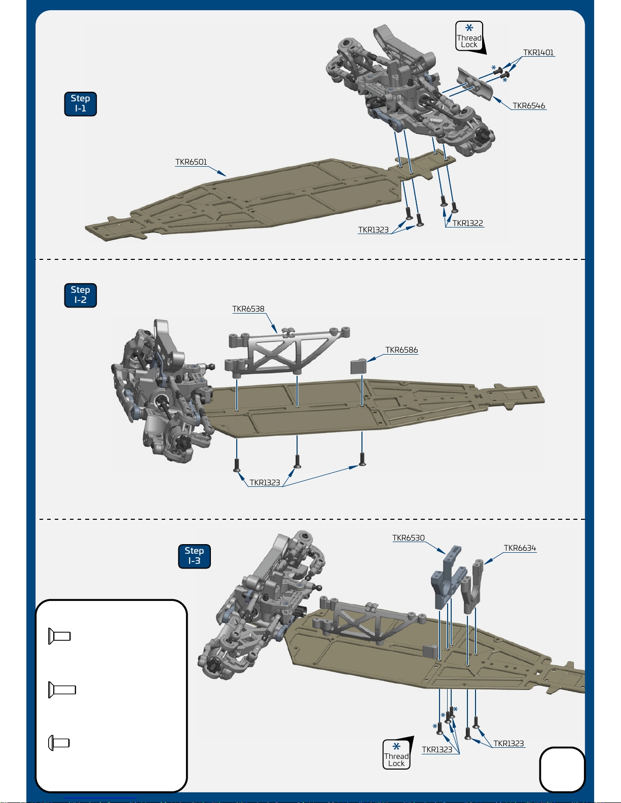
TKR1323
TKR6501
TKR6586
TKR1323
TKR1322
TKR1401
TKR6546
TKR1323
TKR1323
TKR6530
TKR6634
TKR6538
Step
I-1
Step
I-2
Step
I-3
TKR1322
M3x8mm Flat Head Screw
x2
TKR1401
M3x6mm Button Head Screw
x2
TKR1323
M3x10mm Flat Head Screw
x10
Thread
Lock
Thread
Lock
Bag I
Front/Center
Assembly
15
Page 16
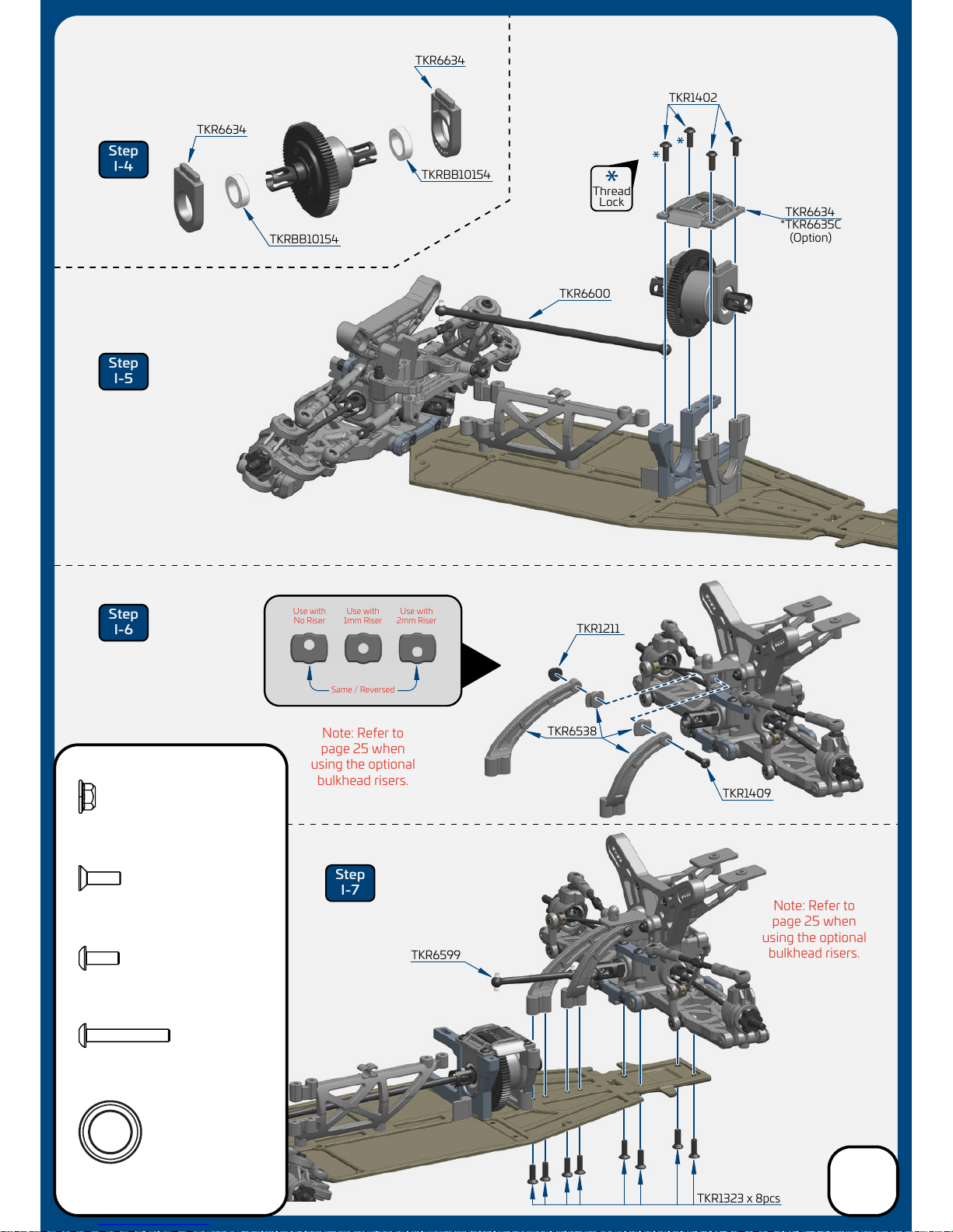
Same / Reversed
Use with
No Riser
Use with
1mm Riser
Use with
2mm Riser
Thread
Lock
Step
I-4
Step
I-5
Step
I-6
Step
I-7
TKR1402
TKR6634
TKR6634
TKR6600
TKR1211
TKR1409
TKR1323 x 8pcs
TKR6634
TKRBB10154
TKRBB10154
TKRBB101504
Ball Bearing(10x15x4mm)
x2
TKR1211
M3 Lock Nut Flange Black
x1
TKR1409
M3x20mm Button Head Screw
x1
TKR1323
M3x10mm Flat Head Screw
x8
TKR1402
M3x8mm Button Head Screw
x4
TKR6599
TKR6538
Note: Refer to
page 25 when
using the optional
bulkhead risers.
Note: Refer to
page 25 when
using the optional
bulkhead risers.
*TKR6635C
(Option)
Bag I
Center/Rear
Assembly
16
Page 17
#500
shock oil
TKR1240
TKR1211
Note: Slot in spring
perch should face
outside of car.
Note: Black screw
is RH threaded.
It goes on the left
side of the car.
Silver screw is
LH threaded.
It goes on the right
side of the car.
TKR1211
TKR6712
TKR6527
Thread
Lock
TKR6712
TKR6709
TKR6710
TKR6712
TKR6707
TKR1245
TKR6705
TKR6703
TKR6701
TKR6548
*TKR6703T
(Option)
*TKR6731
*TKR6732
(Option)
Note: Use green
slime or oil on
shock shaft
threads AND
O-rings to
prevent tearing
and leaking.
Note: Screw rod end on
until distance measures
23mm at full extension.
TKR1604
TKR6701
TKR6785
*TKR6783
*TKR6784
*TKR6786
*TKR6787
(Option)
TKR6712
*TKR6712A
(Option)
#500
Refer to filling
instructions on
page 19 during
this step.
Step
J-1
Step
J-2
Step
J-3
Step
J-4
Step
J-5
TKR1240
M3x18mm Shock Mnt Screw
x2
TKR1248
M2x4mm Emulsion Screw
x2
TKR1245
M2x5mm Piston Screw
x2
TKR1211
M3 Lock Nut Flange Black
x4
TKR1604
M3x8mm Set Screw
x2
23.00
TKR6719A
Note: 1.7mm
piston with
writing up.
Bag J
Front Shock
Assembly
17
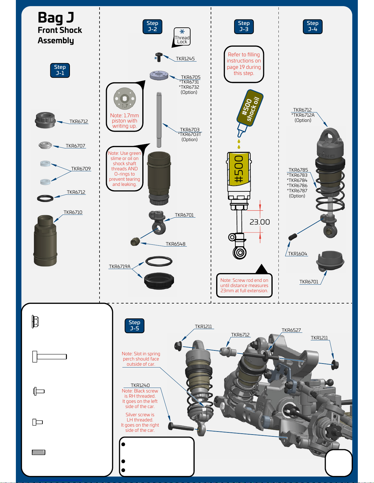
Stock shock position is outside
hole on the arm and 2nd from
inside hole on the tower (2/B)
Stock front ride height is 18mm
Shock length (droop) is 78mm
Page 18
TKR1240
TKR1211
Note: Slot in spring
perch should face
outside of car.
TKR1211
TKR6712
TKR6527
TKR6712
TKR6709
TKR6711
TKR6707
TKR1245
TKR6701
TKR6548
TKR1604
TKR6701
TKR6795
*TKR6793
*TKR6794
*TKR6796
*TKR6797
(Option)
TKR6712
*TKR6712A
(Option)
TKR6719A
Step
K-1
Step
K-2
Step
K-3
Step
K-4
Step
K-5
TKR1240
M3x18mm Shock Mnt Screw
x2
TKR1248
M2x4mm Emulsion Screw
x2
TKR1245
M2x5mm Piston Screw
x2
TKR1211
M3 Lock Nut Flange Black
x4
TKR1604
M3x8mm Set Screw
x2
#500
shock oil
Note: Screw rod end on
until distance measures
28mm at full extension.
#500
Refer to filling
instructions on
page 19 during
this step.
28.00
TKR6712
Note: Black screw
is RH threaded.
It goes on the right
side of the car.
Silver screw is
LH threaded.
It goes on the left
side of the car.
TKR6704
*TKR6704T
(Option)
TKR6705
Thread
Lock
Note: Use green
slime or oil on
shock shaft
threads AND
O-rings to
prevent tearing
and leaking.
*TKR6731
*TKR6732
(Option)
Note: 1.8mm
piston with
writing up.
Bag K
Rear Shock
Assembly
18
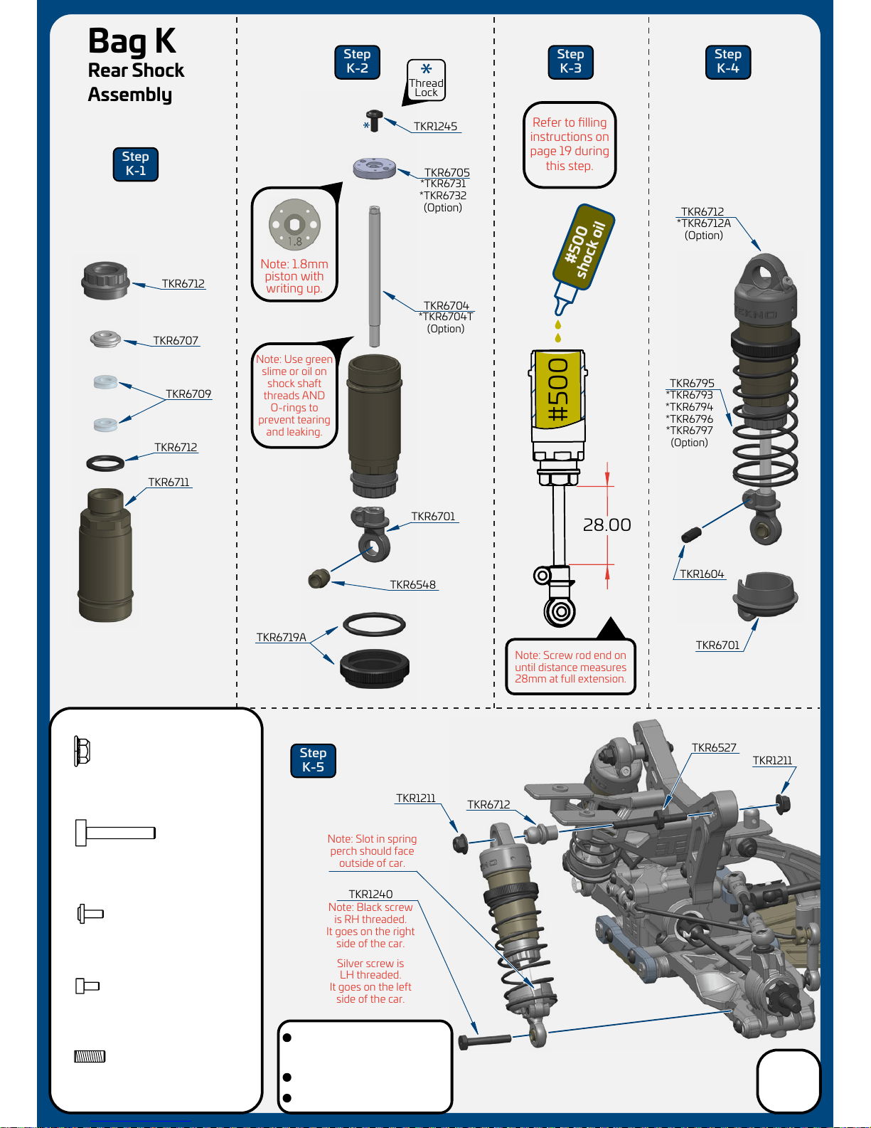
Stock shock position is outside
hole on the arm and 2nd from
inside hole on the tower (2/B)
Stock rear ride height is 21mm
Shock length (droop) is 88mm
Page 19
Shock Filling Instructions
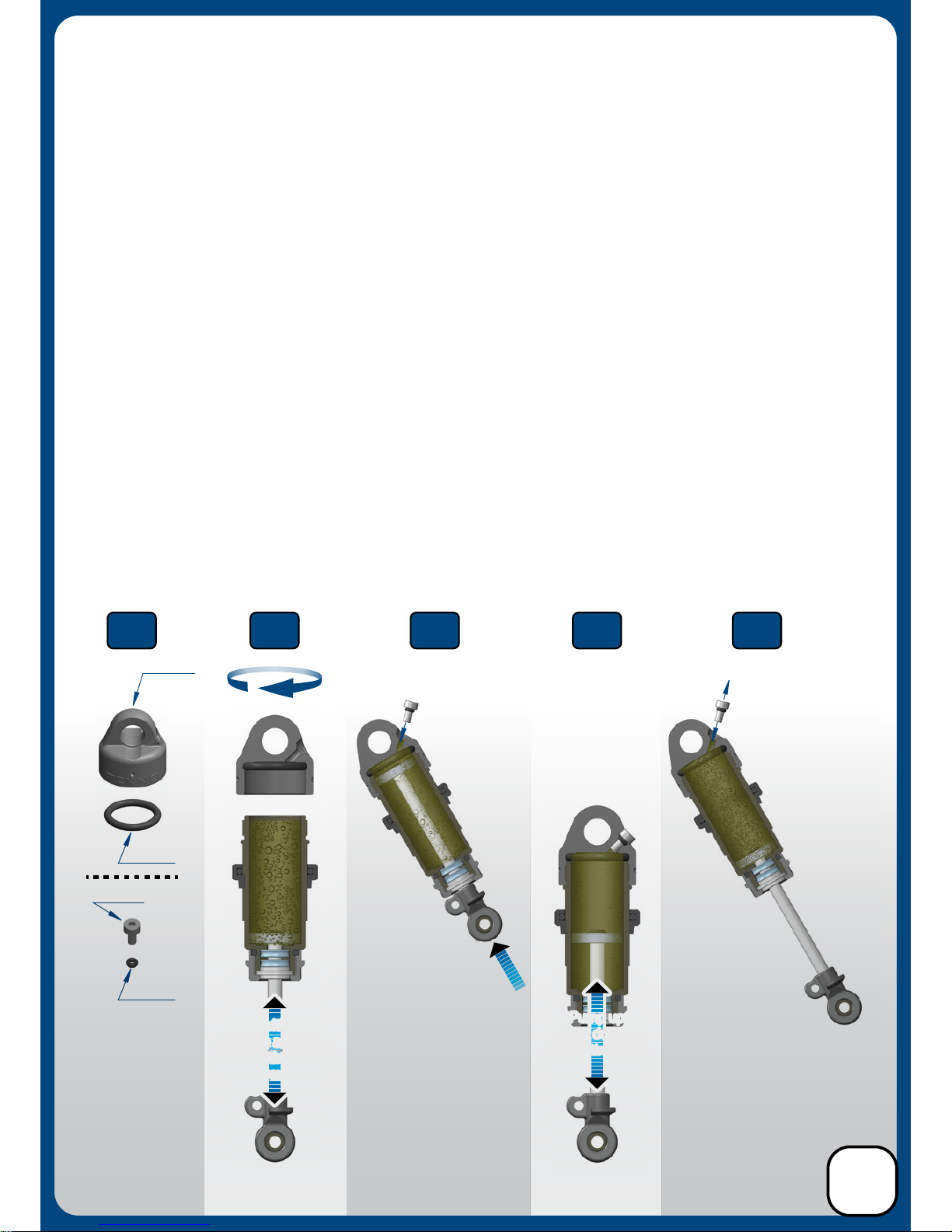
For both front and rear shocks
Step 1. Insert all four larger o-rings into the emulsion caps (there may be a bit of flashing that
should be cleared around the bleeder hole as well) and set aside. Install the small o-rings onto the small
emulsion screws by placing the o-rings on a pit mat or towel and pressing the screws into the o-rings
(add 1 small drop of oil onto the seal to help make the screw slide in easier).
Step 2. Fill shock with oil all the way to the top and pump the shock shaft up and down 3-5 times.
Step 3. Screw on the cap all the way tight (shock tool TKR1115 is helpful for holding the shock body).
Be careful to not cross-thread the caps. Start by turning in the oposite direction before tightening.
Step 4. With the shock at about a 45° angle, push and hold the shock shaft to the top of the stroke and
insert the prepared emulsion screw/seal. Oil will leak out during this process. Tighten the screw until
snug (do not over-tighten). Wipe o excess oil before moving on to step 5.
Step 5. Pump the shock shaft up and down about 20 times vigorously. This emulsifies the oil.
Step 6. With the shock shaft fully extended, remove the emulsion screw from the cap to do the final bleed.
Step 7. With the shock at about a 45° angle, push and hold the shock shaft to the top and insert the
prepared emulsion screw/seal again. Oil will leak out during this process. Finish by tightening the screw
until snug (do not over-tighten).
We've found it's easiest to complete steps 1 & 2 on each shock before moving on to step 3.
By the time you've finished step 2 on the last shock, the first one will be ready for step 3.
Fill with oil,
Pump up and down
3-5 times,
Then screw on cap
Fill with oil,
Pump up and down
3-5 times,
Then screw on cap
Pump up
and down
30 times
Pump up
and down
20 times
Prepare caps by
inserting seals
AND
Push smaller
screws into small
o-rings
Push shaft up
to bleed air out
THEN
Insert screw snug
(do not over-tighten)
TKR6714
TKR6714
TKR6712
TKR1248
Pull shaft down,
remove screw
THEN
Push shaft up to bleed air,
insert screw snug
(do not over-tighten)
Step
1
Step
2-3
Step
4
Step
5
Step
6-7
19
Page 20
TKR1321
M3x6mm Flat Head Screw
x2
TKR1323
M3x10mm Flat Head Screw
x6
TKR1221
M3X8mm Washer
x6
TKR1522
M3x8mm Cap Head Screw
x2
TKR1403
M3x10mm Button Head Screw
x2
TKR1409
M3x20mm Button Head Screw
x2
TKR1523
M3x10mm Cap Head Screw
x2
TKR1409
Steering servo (not included)
For Low Profile servo
installation, see page 24.
For Low Profile servo
installation, see page 24.
TKR1323
TKR1323
TKR1409
TKR1221
TKR6586
TKR6685
TKR1523
TKR1221
TKR1523
TKR1221
TKR1221
TKR1321
TKR6586
TKR6586
TKR6539
TKR1522
TKR1403
Screws
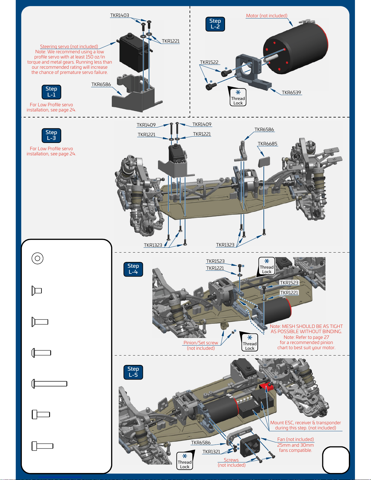
Note: Refer to page 27
for a recommended pinion
chart to best suit your motor.
Note: MESH SHOULD BE AS TIGHT
AS POSSIBLE WITHOUT BINDING.
Motor (not included)
Fan (not included)
(not included)
Pinion/Set screw
(not included)
25mm and 30mm
fans compatible.
Mount ESC, receiver & transponder
during this step. (not included)
Step
L-1
Step
L-3
Step
L-4
Step
L-5
Step
L-2
TKR1221
Thread
Lock
Thread
Lock
Thread
Lock
Thread
Lock
Note: We recommend using a low
profile servo with at least 150 oz/in
torque and metal gears. Running less than
our recommended rating will increase
the chance of premature servo failure.
Bag L
Final Assembly
20
Page 21
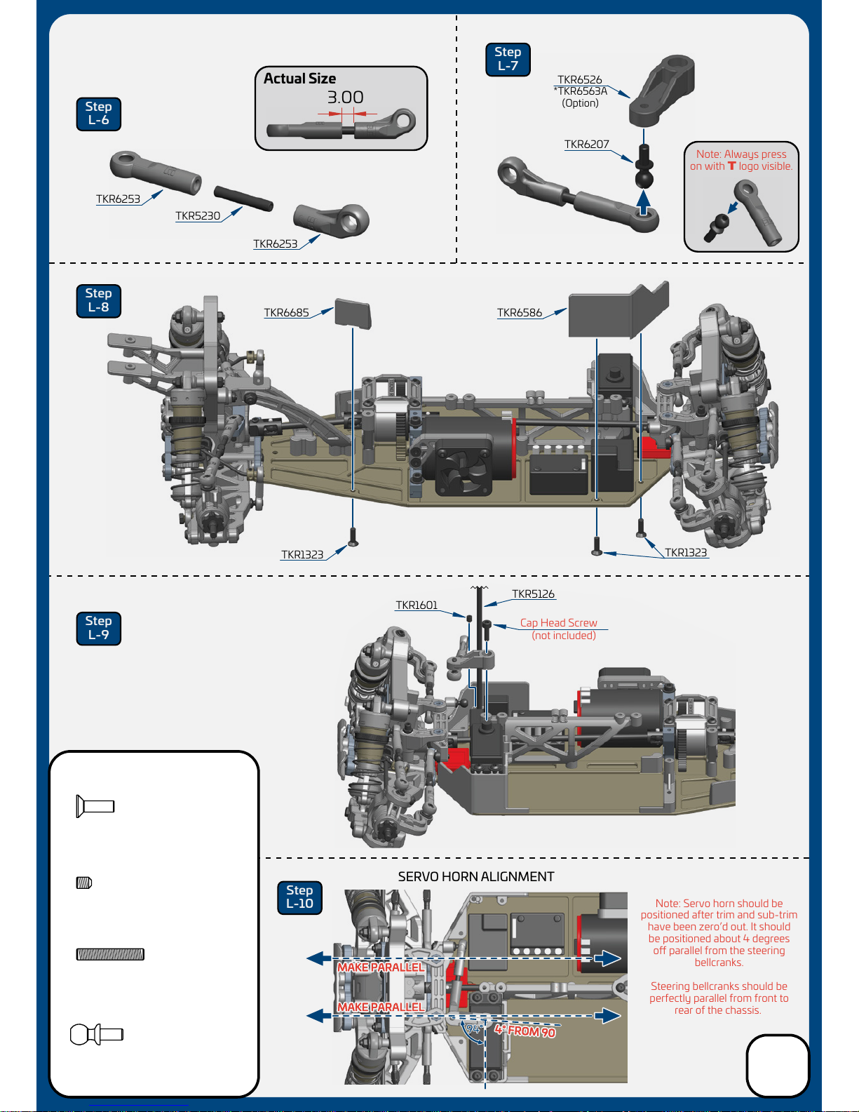
3.00
Note: Servo horn should be
positioned after trim and sub-trim
have been zero’d out. It should
be positioned about 4 degrees
o parallel from the steering
bellcranks.
Steering bellcranks should be
perfectly parallel from front to
rear of the chassis.
Step
L-6
Step
L-7
Step
L-8
Step
L-9
Step
L-10
TKR5230
M3x18 Threaded Rod
x1
TKR6253
TKR1323
TKR1601
TKR1323
TKR5126
TKR6685
TKR6586
TKR6253
TKR6207
TKR6526
TKR5230
TKR6207
M3x6mm Ball Stud
x1
TKR1323
M3x10mm Flat Head Screw
x3
TKR1601
M3x4mm Set Screw
x1
Cap Head Screw
(not included)
SERVO HORN ALIGNMENT
Actual Size
Note: Always press
on with T logo visible.
*TKR6563A
(Option)
Bag L
Final Assembly
21
Page 22
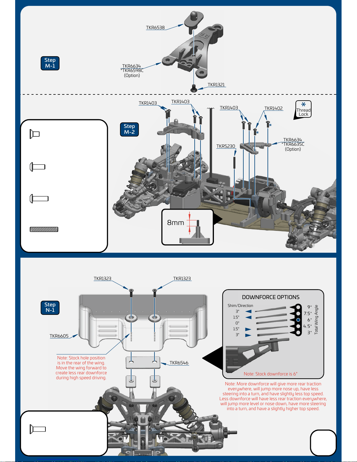
Note: Stock downforce is 6°
Note: Stock hole position
is in the rear of the wing.
Move the wing forward to
create less rear downforce
during high speed driving.
Note: More downforce will give more rear traction
everywhere, will jump more nose up, have less
steering into a turn, and have slightly less top speed.
Less downforce will have less rear traction everywhere,
will jump more level or nose down, have more steering
into a turn, and have a slightly higher top speed.
DOWNFORCE OPTIONS
3°
Shim/Direction
Total Wing Angle
1.5°
0°
1.5°
3°
TKR6538
TKR6634
TKR1403
TKR1403
TKR1403
TKR1402
TKR5230
TKR1323 TKR1323
TKR6605
TKR6546
TKR1321
TKR6634
Step
M-1
Step
N-1
Step
M-2
Thread
Lock
8mm
*TKR6635C
(Option)
*TKR6598C
(Option)
Bag M
Final Assembly
Bag N
Wing
22
TKR1323
M3x10mm Flat Head Screw
x2
TKR1321
M3x6mm Flat Head Screw
x1
TKR5230
M3x18 Threaded Rod
x1
TKR1403
M3x10mm Button Head Screw
x6
TKR1402
M3x8mm Button Head Screw
x2
Page 23
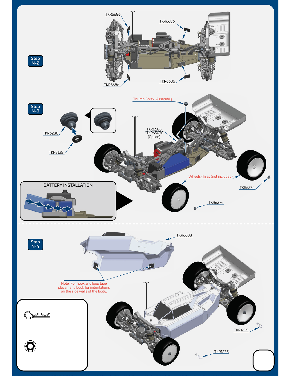
Note: For hook and loop tape
placement. Look for indentations
on the side walls of the body.
BATTERY INSTALLATION
TKR6280
TKR5125
TKR6686
TKR6686
Thumb Screw Assembly
Wheels/Tires (not included)
TKR6686
TKR6686
TKR1235
TKR6274
TKR6586
TKR1235
TKR6274
TKR6608
Step
N-2
Step
N-3
Step
N-4
TKR1235
Body Clip
x2
TKR6274
Wheel Nut
x4
*TKR6503C
(Option)
Bag N
Body/Tires
23
Page 24
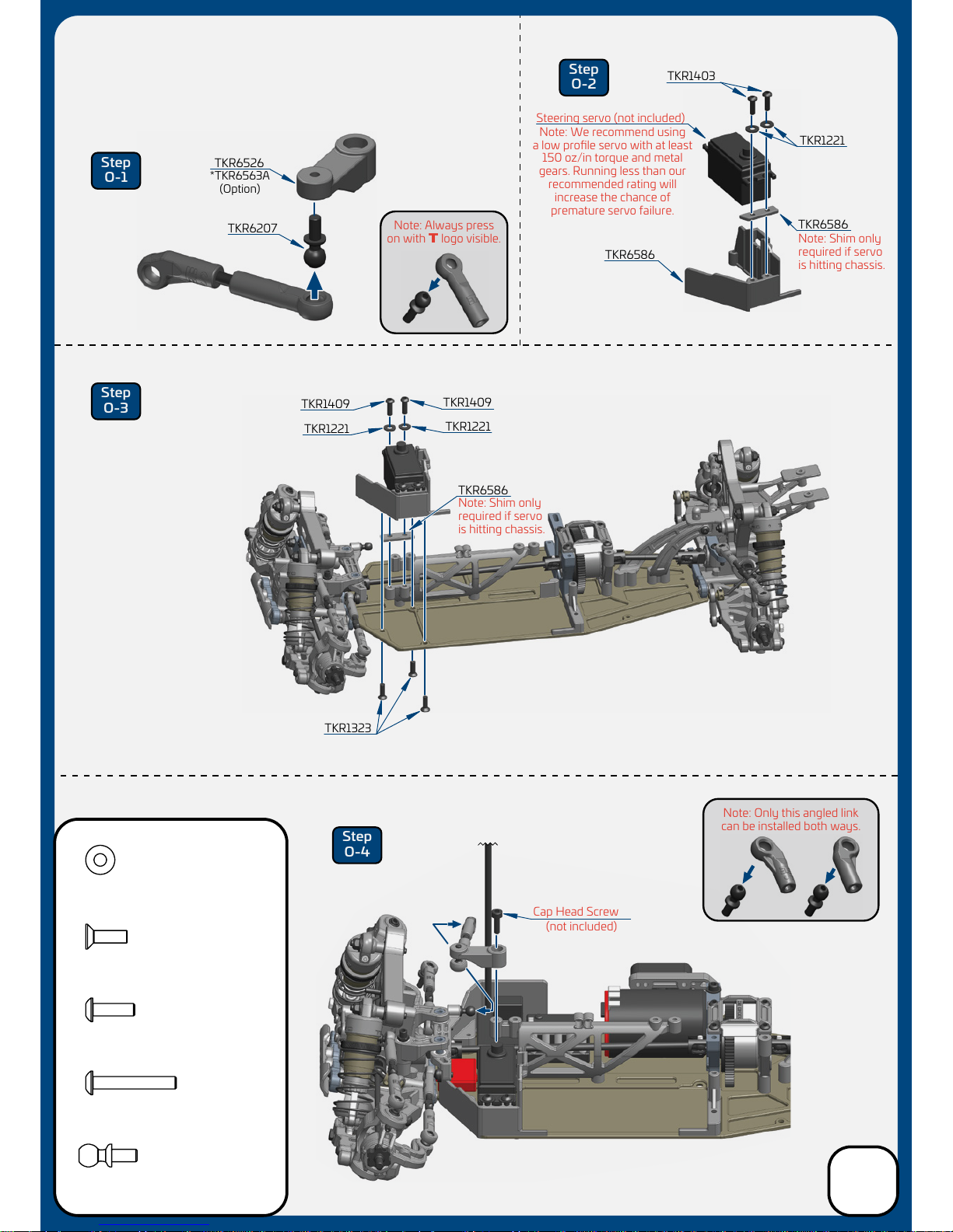
Step
O-1
Step
O-2
Step
O-3
Step
O-4
Cap Head Screw
(not included)
Steering servo (not included)
TKR6586
TKR6586
TKR1403
Note: We recommend using
a low profile servo with at least
150 oz/in torque and metal
gears. Running less than our
recommended rating will
increase the chance of
premature servo failure.
Note: Shim only
required if servo
is hitting chassis.
Note: Shim only
required if servo
is hitting chassis.
TKR1221
TKR6207
TKR6526
TKR1409
TKR1323
TKR1409
TKR1221
TKR1221
TKR6586
TKR1221
M3X8mm Washer
x4
TKR1403
M3x10mm Button Head Screw
x2
TKR1409
M3x20mm Button Head Screw
x2
TKR6207
M3x6mm Ball Stud
x1
TKR1323
M3x10mm Flat Head Screw
x3
Note: Always press
on with T logo visible.
Note: Only this angled link
can be installed both ways.
*TKR6563A
(Option)
Bag O
Optional Low Profile
Servo Mounting
24
Page 25
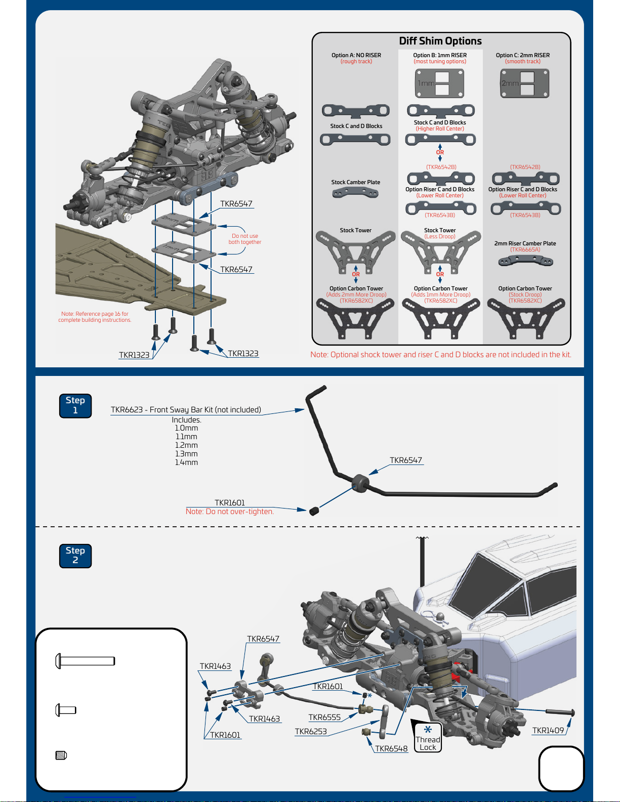
Step
1
Step
2
TKR1409
M3x20mm Button Head Screw
x2
TKR1601
TKR6547
Note: Do not over-tighten.
Note: Optional shock tower and riser C and D blocks are not included in the kit.
TKR6547
TKR6547
TKR1323
TKR1323
TKR6623 - Front Sway Bar Kit (not included)
Includes.
1.0mm
1.1mm
1.2mm
1.3mm
1.4mm
TKR1601
TKR1463
TKR1463
TKR6547
Thread
Lock
TKR1601
TKR6555
TKR6548
TKR1409
TKR6253
x3
TKR1601
M3x4mm Set Screw
TKR1463
M2.5x6mm Button Head Screw
x2
Option A: NO RISER
(rough track)
Stock Tower
Option Carbon Tower
(Adds 2mm More Droop)
(TKR6582XC)
Option Carbon Tower
(Adds 1mm More Droop)
(TKR6582XC)
Option Carbon Tower
(Stock Droop)
(TKR6582XC)
2mm Riser Camber Plate
(TKR6665A)
(TKR6542B)(TKR6542B)
(TKR6543B)(TKR6543B)
Stock C and D Blocks
Option B: 1mm RISER
(most tuning options)
Stock C and D Blocks
(Higher Roll Center)
Stock Camber Plate
Option Riser C and D Blocks
(Lower Roll Center)
Stock Tower
(Less Droop)
Option C: 2mm RISER
(smooth track)
Option Riser C and D Blocks
(Lower Roll Center)
Di Shim Options
OR OR
OR
Do not use
both together
Note: Reference page 16 for
complete building instructions.
Optional
Di Shims/
Front Sway Bar
25
Page 26
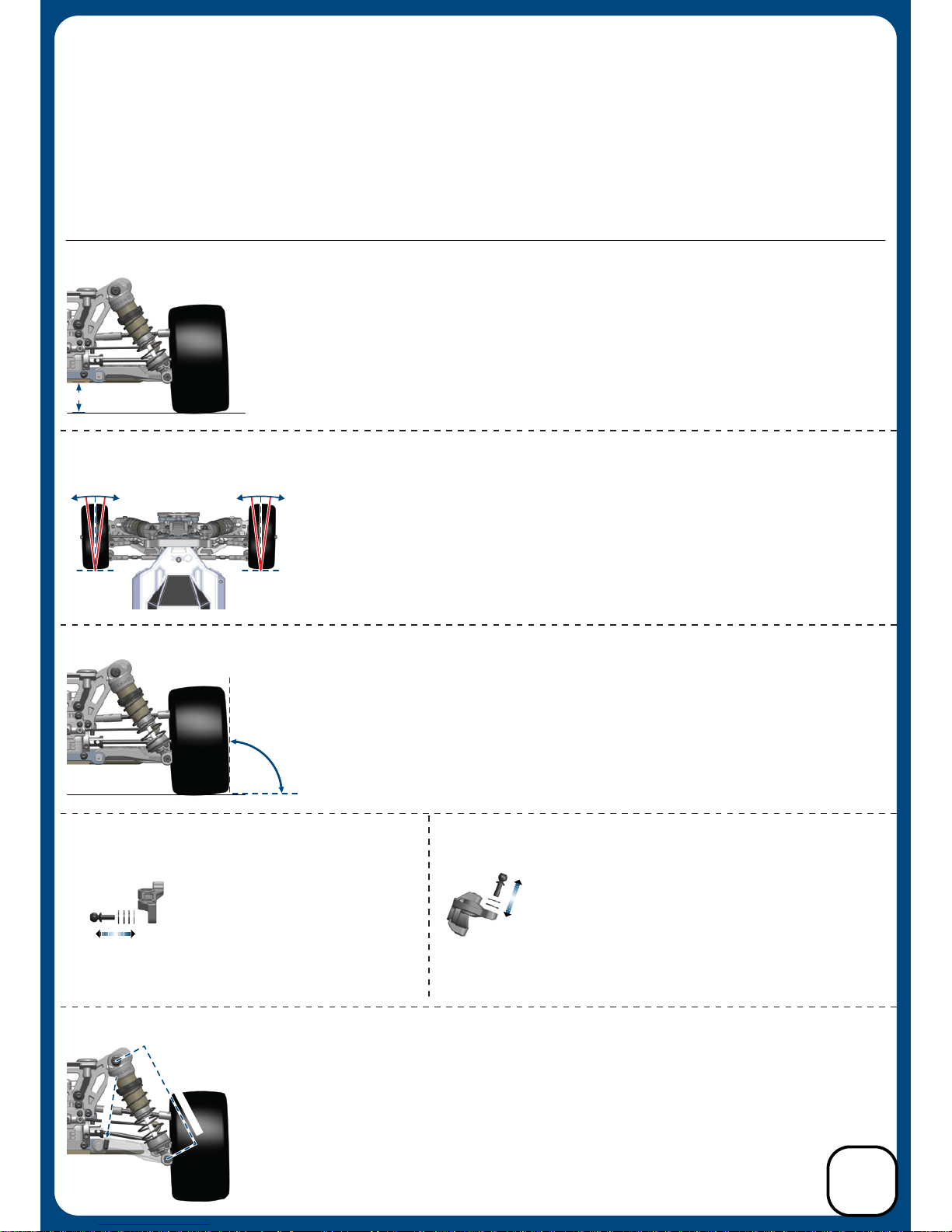
The purpose of making adjustments is to make the car go faster around the track, or to make it more controllable, or both if possible. A car
that's easier to drive should produce lower, more consistent lap times. It will also inspire more confidence in the driver, which is always
good when nerves start getting the best of you.
Before you start thinking about changing your car's setup, consider these two things: First, is the car in perfect working order? Be sure
that all of the suspension components operate freely without excessive play, and that the car isn't tweaked. Binding and worn out parts
will result in poor performance and inconsistent handling. Second, always consider tires before making other adjustments. Time spent
trying to get the vehicle to work with the wrong tires mounted will be wasted time. Without the right tires, even a great setup won’t be a
winning setup.
Bumpsteer
M
O
R
E
b
u
m
p
o
u
t
b
u
m
p
o
u
t
L
E
S
S
Ackermann
Eect
LESS MORE
D
R
O
O
P
M
E
A
S
U
R
E
M
E
N
T
A
D
J
U
S
T
H
E
R
E
Droop
Ride height is the distance from the bottom of the chassis to the running surface. Ride height should
only be checked and adjusted with your vehicle ready to run (i.e. with battery installed/body on). Ride
height is the first adjustment to be made and should be set with a ride height measurement tool. Measurements should be taken from the flat parts of the chassis, front and rear. Be sure to measure the
front ride height at a point before the kick up in the chassis starts. To measure ride height, first make
sure the suspension is completely free, then simultaneously compress the front and rear all the way
down and let the vehicle settle. Take your measurement from that position. Use the shock spring
adjustment collars to raise or lower the ride height to your desired setting. 18 - 20mm front and 21 23mm rear is a good starting point.
Think of bump steer as active toe when the suspension compresses or rebounds. To adjust bump steer
you have to change the angle of the steering link.
This is accomplished by adding or removing washers
under the ball end on the steering spindles. Anytime
you change camber link locations, front arm pills,
front arm spacers, or Ackermann you will need to
check and possibly adjust your bumpsteer. It's best
to start with zero bumpsteer or slight bump out.
Think of Ackermann as active toe
when the steering moves from left
to right. More ackermann eect
makes more toe out at full turn and
produces more steering o-power.
Less ackermann eect makes less
toe out at full turn and produces
more steering on-power. A good
starting point is 4 washers behind
the ball stud (2mm).
Ride Height
MEASUREMENT
Camber
C
A
M
B
E
R
Static camber aects the car’s side to side traction. More negative camber front and rear quickens rotation in corners. Less negative camber will make the vehicle easier to drive but you may
give up some responsiveness (i.e. steering). To set your static camber have your vehicle at ride
height (see above) and adjust the camber links until desired angle is achieved. Please note that a
large adjustment of front camber will aect front toe and you may have to readjust the toe and
then re-check front camber again. A good starting measurement for camber is 1-2 degrees in
the front and 1.5-2.5 degrees in the rear.
Front toe is used to describe the angle in which the front wheels point when looking down at
them from the top of a vehicle. You will always use some amount of toe out. Toe-out will
aect how your vehicle enters and exits corners. More toe out will result in more o-power
steering and less on-power steering and less toe out will have the opposite results. To set your
front toe, have your vehicle at ride height (see above) and adjust the steering links until desired
angle is achieved. Please note that a large adjustment of front toe will aect front camber and
you may have to readjust the camber and then re-check front toe again. A good starting point
is approximately 1-2 degrees of toe out.
Droop is the measured amount of down travel in the suspension. It is measured from the shock mounting
points while the vehicle is up on a stand allowing the arms to hang freely and is adjusted by turning the
droop screw located in the suspension arms front/rear. This screw limits the suspension travel by
providing a stopping point against the chassis. Left and right sides should always be equal, however the
front and rear of the vehicle can have dierent values. Droop aects all aspects of chassis
performance, including: braking, acceleration, jumping, traction and bump handling. A good
starting droop measurement is 78mm front and 88mm rear.
Front Toe
O
U
T
_
_
_
_
I
N
I
N
_
_
_
_
O
U
T
26
Set Up Information
Page 27
Vehicle
(2 cell)
(50-80 ft Straight)
Small Track
(pinion/spur)
Large Track
(pinion/spur)
(80-150 ft Straight)
EB410
Motor
5.5T
6.5T
7.5T
8.5T
10.5T
18/81 tooth
19/81 tooth
20/81 tooth
20/76 or 21/81
21/76 or 22/81
19/81 tooth
20/81 tooth
21/81 tooth
21/76 or 22/81
22/76 or 23/81
13.5T
25/70 tooth 26/70 tooth
TKRBB040725 – Ball Bearings (4x7x2.5mm,
sold in pack of 4pcs) Bearings for the
bellcrank/ackerman plate. 8pcs required in kit.
TKRBB05114 – Ball Bearings (5x11x4, 4pcs)
Di pinion support bearings for the front/rear
transmission housings. 4pcs required in kit.
TKRBB10154 – Ball Bearings (10x15x4mm,
sold in pack of 4pcs) Bearings for all three dis.
Also inner front steering blocks/rear hub carriers.
10pcs required in kit.
TKRBB06124 – Ball Bearings (6x12x4mm, 4pcs)
Bearings for outside of steering blocks and outer
rear hub carriers. 4pcs required in kit.
PAR T#/COLOR F / R
Rear
Rear
Rear
Front
Front
Front
Front
Rear
Rear
1.2
1.2
7.75
7.38
53mm
53mm
2.82
3.02
Front
TKR6796
TKR6797
TKR6793
TKR6794
TKR6795
TKR6784
TKR6785
TKR6786
TKR6787
TKR6783
WIRE DIA.
1.2
1.2
1.2
1.3
1.3
1.3
1.3
1.3
COILS
9.38
8.75
8.25
9.0
8.5
8.13
7.75
9.5
LENGTH
53mm
53mm
53mm
45mm
45mm
45mm
45mm
45mm
LENGTH
COILS
WIRE DIA.
2.20
2.41
2.60
3.16
3.41
3.62
3.85
2.95
RAT E
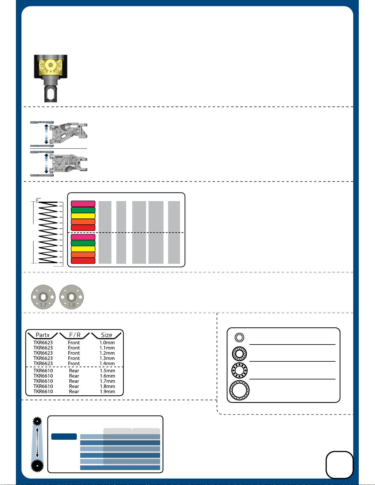
Changes to wheelbase can aect the overall handling of your vehicle, since it adjusts the distribution
of weight on the wheels as well as the angle of the driveshafts. Shortening the wheelbase at the
rear will give you more steering into a turn and o power, less steering out of a turn and on power.
Lengthening the wheelbase at the rear will yield the opposite results.
Shortening the wheelbase in the front will land jumps a little better and lengthening it will be better
through small bumps. In general a longer wheelbase is better on open and/or bumpy tracks and a
shorter wheelbase is better on tighter technical tracks.
This chart shows the recommended starting ratios for the
common motor winds. Please consult the motor/esc manufacturers recommended settings to ensure you start with the
best final drive ratio (FDR) for your equipment. When setting
your mesh you want to be able to slightly rock the spur gear
back and forth without moving the pinion gear. Tekno RC is
not responsible for damage done to your electronic equipment
or gears due to improper gearing or mesh.
* For bearing maintenance, please refer to page 28.
Softer springs will increase traction through the turns by allowing
more roll, slow down the responsiveness of the vehicle, and can
be better in the bumps. Stier springs will increase corner speed
if traction is available and will also tend to jump and land better.
Once you find a set of springs you like you will typically only
change them for tracks with dramatically dierent conditions.
Sway bars are used to adjust a
vehicle's lateral grip by resisting
chassis roll. A thicker bar
decreases roll more than a
thinner bar will. More roll means
more grip and less roll means
less grip. The front sway bar
aects mainly o-power
steering at corner entry. The
rear sway bar aects mainly
on-power steering and stability
in mid-corner and at corner exit.
Pistons with smaller holes work well for smoother tracks with large jumps and pistons with larger holes work
well for rougher tracks with less jumps. Smaller hole pistons will typically use thinner oil than larger hole
pistons. Shock oil is also aected by the ambient temperature so a change in viscosity might be necessary
with a change of 5°C or ~10°F.
Front Arm
Rear Arm
Wheelbase Adjustments
FORWARD
BACKWARD
FORWARD
BACKWARD
Front: Changing front di oil aects overall steering response. Thinner can increase o-power steering but
the vehicle may be twitchy and harder to drive. Thicker can increase on power steering and stability. We
recommend 10k to 20k in the front di.
Center: Changing center di oil aects the front-to-rear drive balance. Thicker will reduce o-power
steering and on-power rear traction but increases on-power steering and acceleration if traction is available.
Thinner will increase o-power steering and on-power rear traction but reduce on-power steering and
acceleration. We recommend 10k to 30k in the center di.
Rear: Thinner rear di oil increases o-power steering and reduces traction into a corner. It also reduces
on-power steering and increases traction out of a corner. Going too thin will make your vehicle inconsistent,
however. Thicker rear oil will have opposite eects, and once again, going too thick will make the vehicle
inconsistent. We recommend 5k to 10k in the rear di.
Dierentials
Springs
Pistons
Sway Bars Bearing Chart
Gearing Recommendations
27
Set Up Information
(continued)
Page 28
Bearing Maintenance:
Performing regular maintenance will greatly improve your on track consistency and also extend the life of your vehicle.
Going through critical areas of the vehicle regularly will also allow you to find possible issues before they become a
problem that may cost you a race. Follow the guidelines below for maximum performance.
Bearings should always be smooth and free in order to preform their function. We recommend inspecting and cleaning
each bearing on a regular basis. It will be necessary to break down parts of the vehicle in order to inspect them properly.
The procedures below should be done every couple of weeks or prior to an important race.
1. Inspect the outer seals for any visible damage and check the rolling resistance of each bearing.
2. If any bearing does not spin freely, then take the following steps to clean them.
3. Spray the bearing with motor spray and spin it again to remove any debris trapped inside. Repeat if necessary. If
the bearing does not start to spin freely after cleaning, then they may need to be replaced.
4. Allow the clean bearing to dry or blow into the bearing with compressed air to speed up the drying process.
5. Oil each bearing with a proper bearing lubricant. One or two drops is enough.
Shock Maintenance:
When comparing the left and right shocks of the front end, they should feel identical. Same goes for the rears.
The procedures below should be done every race day to make sure they are leak free and operating correctly.
1. After removing the shocks from the vehicle, remove the springs and inspect each shock for visible leaks (build up of
debris at the bottom of the shock shaft or visible oil).
2. If the shock binds when pushing the shaft through its stroke, then the shaft may be bent and will need to be replaced.
3. If the shocks from left to right do not feel consistent when compared to each other, or have built up too much air
inside (feel empty when pushing the shaft through its stroke), then you will need to rebuild them following the steps
outlined on page 19 of this manual.
Properly maintained dierentials are essential for a smooth operating vehicle. Check all three dis regularly to make
sure they are filled and operating as designed.
1. Remove each di and verify the dierential action is happening and is smooth. If there is any notchy feel to them,
follow the steps below to rebuild them.
2. Open the di and pour out the oil. Remove the gears and pins to release the outdrives. Then remove the
seals. Inspect everything to make sure there are no damaged parts. If the seals are old or show any signs
of degradation, replace them immediately. Re-lubricate the seals and outdrives, then rebuild the di
following the steps on page 3 and 4.
Hinge Point & Drive Line Maintenance:
Dierential Maintenance:
Checking the hinge points while the shocks are removed from the vehicle is the best time to inspect these parts. The
other items to inspect are the camber links, steering links and drive shafts. Follow the steps below every couple of
weeks in order to keep the vehicle preforming at maximum.
1. With the shocks o the vehicle, check the movement of the arms, hubs and spindle carriers. They should move
freely. If there is a bind, then the inner or outer hinge pin may be bent and would need to be replaced. The arms
should not have any play when twisted or moved in any direction against the hinge points. If there is excessive
slop present, then the arms or hubs may be worn and will need to be replaced.
2. Remove the camber links, steering links and servo link from the vehicle. Check the movement of the spindles to see
if they turn freely. If they don’t, then check the kingpin shoulder screws to see if they are tightened down too far.
Also, check for slop. If there is excessive slop present, then the spindle carriers may need to be replaced.
3. Check the steering rack to make sure it moves freely. If it binds, then the screws holding the Ackermann or the
steering posts could be too tight. If they still bind, then check the bearings and follow the steps above to clean them.
4. After re-installing the camber links, steering links and servo link, check the movement of the rod ends on the ball
studs. If they have excessive slop or are binding, then they may need to be replaced.
5. Check the drive shafts by rotating them. Look for any wobbles. If they are bent, replace them immediately.
6. With the drive shafts removed, check for slop in the CV area. If it is present, then reposition the CV pin to another
fresh hole, re-lubricate and install back into the vehicle.
Maintenance:
28
Page 29
29
TKR6500 - EB410 1/10th Comptetion 4x4 Buggy Complete Kit
Parts List
TKR5125 - O-Ring (ESC tray, 3pcs)
TKR5126 - Antenna tube (universal, w/ caps, 5pcs)
TKR5230 - Steering linkage (M3x18mm threaded rod, 10pcs)
TKR5571M - Wheel Hexes (12mm, steel, lightened, 4pcs)
TKR6206 - Ball Stud (5.5mm, short neck, 6mm thread, 4pcs)
TKR6207 - Ball Stud (5.5mm, long neck, 6mm thread, 4pcs)
TKR6208 - Ball Stud (5.5mm, short neck, 8mm thread, 4pcs)
TKR6210 - Ball Stud (5.5mm, short neck, 10mm thread, 4pcs)
TKR6250 - Turnbuckle (M3 thread, 55mm length, 4mm adjustment, 2pcs)
TKR6252 - Turnbuckle (M3 thread, 40mm length, 4mm adjustment, 2pcs)
TKR6253 - Rod End Set (turnbuckles, sway bar, steering, EB410)
TKR6270R - Stub Axles (rear, hardened steel, EB410, 2pcs)
TKR6274 - Wheel Nuts (7mm, serrated, gun metal ano, M4, 4pcs)
TKR6280 - Battery Strap Thumb Screw (EB410)
TKR6501 - Chassis (7075, 3mm, hard anodized, lightened, EB410)
TKR6519 - Bulkhead Set (f/r, EB410)
TKR6523 - Hinge Pins (inner, front/rear, super hard, EB410, 2pcs)
TKR6524 - Suspension Arms (rear, EB410)
TKR6525 - Suspension Arms (front, EB410)
TKR6526 - Bell Cranks, Ackerman Plate, Servo Horns (EB410)
TKR6527 - Shock Standos (EB410, 2pcs)
TKR6530 - Motor Mount Base (CNC, 7075, EB410)
TKR6538 - Chassis Brace, Body Mount Set (EB410)
TKR6539 - Motor Mount Insert (CNC, 7075, EB410)
TKR6540 - Hinge Pin Brace (CNC, 7075, EB410, A Block)
TKR6541 - Hinge Pin Brace (CNC, 7075, EB410, B Block)
TKR6542 - Hinge Pin Brace (CNC, 7075, EB410, C Block)
TKR6543 - Hinge Pin Brace (CNC, 7075, EB410, D Block)
TKR6544 - Hinge Pin Inserts, Wheelbase Shims (EB410)
TKR6545 - Rear Hubs (l/r, EB410)
TKR6546 - Wing Mount and Bumper (EB410)
TKR6547 - Sway Bar and Bulkhead Acc. (EB410)
TKR6548 - Pivot Balls (5.5mm, flanged, 4pcs)
TKR6552 - Spindle Carriers (l/r, EB410)
TKR6553 - Spindles (15°, l/r, EB410)
TKR6555 - Stabilizer Balls (5.5mm, sway bars, aluminum, 4pcs)
TKR6565 - Hinge Pins (outer, front, EB410, 2pcs)
TKR6566 - Hinge Pins (outer, rear, EB410, 2pcs)
TKR6572 - Driveshaft (rear, hardened steel, 2pcs)
TKR6573F - Stub Axles (front, hardened steel, EB410, 2pcs)
TKR6574 - Driveshaft (front, hardened steel, 2pcs)
TKR6581 - Shock Tower Set (f/r, EB410)
TKR6586 - Side Guard, Servo Mount, Battery Acc. (EB410)
TKR6596 - Kingpin Shoulder Screws (EB410, 4pcs)
TKR6597 - Di Coupler (f/r, lightened, hardened steel, EB410)
TKR6599 - Tapered Driveshaft (center, rear, 7075, black ano, EB410)
TKR6600 - Tapered Driveshaft (center, front, 7075, black ano, EB410)
TKR6605 - Wing (lexan, pre-cut, EB410)
TKR6608 - Body (0.8mm, EB410)
TKR6610 - Sway Bar Set (rear, 1.5, 1.6, 1.7, 1.8, 1.9mm, EB410)
TKR6627 - Steering Rack Bushings (aluminum, EB410, 2pcs)
TKR6629 - Steering Posts (steel, EB410, 2pcs)
TKR6634 - Center Di Support, Top Braces (EB410)
TKR6664 - Front Camber Link Plate (aluminum, EB410)
TKR6665 - Rear Camber Link Plate (aluminum, EB410)
TKR6685 - Rear Body Mount Panels (EB410, 2pcs)
TKR6686 - Body Mount Hook and Loop Tape Set (EB410, 4pcs)
TKR6856 - CV Rebuild kit (f/r, for 2 axles)
Dierential List
TKR5144 - Dierential O-Rings (6pcs)
TKR6511 - Dierential Case (f/c/r, 3pcs, EB410)
TKR6512 - Dierential Ring Gear (40t, use with TKR6551)
TKR6513X - Dierential Cross Pins (composite, 3pcs, EB410)
TKR6514 - Dierential Outdrives (f/r/c, lightened, EB410)
TKR6515 - Dierential Seals (3pcs, EB410)
TKR6517 - Dierential Shims (5x14mm, hardened, 6pcs, EB410)
TKR6522 - Spur Gear (81t, 48pitch, composite, black, EB410)
TKR6550 - Dierential Gear Set (internal gears only, EB410)
TKR6551 - Di Pinion (16t, use with TKR6512)
Bearings List
TKRBB040725 - Ball Bearing (4x7x2.5mm, 4pcs)
TKRBB05114 - Ball Bearing (5x11x4, 4pcs)
TKRBB06124 - Ball Bearing (6x12x4, 4pcs)
TKRBB10154 - Ball Bearing (10x15x4, 4pcs)
Shocks List
TKR6701 - Locking Shock Rod End and Spring Perch Set (13mm shocks)
TKR6703 - Shock Shafts (front, steel, EB410, 2pcs)
TKR6704 - Shock Shafts (rear, steel, EB410, 2pcs)
TKR6707 - Shock Cartridge End Guide Set (CNC, Delrin, 4pcs, EB410)
TKR6709 - Shock X-rings (8pcs, EB410)
TKR6710 - Shock Body (front, aluminum, hard ano, EB410, 2pcs)
TKR6711 - Shock Body (rear, aluminum, hard ano, EB410, 2pcs)
TKR6712 - Shock/Cartridge Cap & Bushing Set (4pcs each, EB410)
TKR6714 - Emulsion O-ring Set (4x cap seals, 8x emulsion o-rings, for 13mm shocks)
TKR6719A - Shock Adjustment Collars (aluminum, EB410, 2pcs)
TKR6785 - Shock Spring Set (front, 1.3x8.5, 3.41lb/in, 45mm, yellow)
TKR6795 - Shock Spring Set (rear, 1.2x8.25, 2.6lb/in, 53mm, yellow)
Hardware List
TKR1201 - M3 Locknuts (black, 10pcs)
TKR1211 - M3 Locknuts (flanged, black, 10pcs)
TKR1221 - M3x8mm Washer (black, 10pcs)
TKR1229 - 6x10x.2 Shims (10pcs)
TKR1235 - Body Clips (angled, 10pcs)
TKR1240 - Lower Shock Mount Screws (2 CW thread, 2 CCW thread)
TKR1245 - Shock Piston Retainer Screw (4pcs)
TKR1248 - M2x4mm Cap Head Screws (black, 10pcs)
TKR1301 - M2.5x6mm Flat Head Screws (black, 10pcs)
TKR1303 - M2.5x10mm Flat Head Screws (black, 10pcs)
TKR1321 - M3x6mm Flat Head Screws (black, 10pcs)
TKR1322 - M3x8mm Flat Head Screws (black, 10pcs)
TKR1323 - M3x10mm Flat Head Screws (black, 10pcs)
TKR1329 - M3x20mm Flat Head Screws (black, 10pcs)
TKR1400 - M3x4mm Button Head Screws (black, 10pcs)
TKR1401 - M3x6mm Button Head Screws (black, 10pcs)
TKR1402 - M3x8mm Button Head Screws (black, 10pcs)
TKR1403 - M3x10mm Button Head Screws (black, 10pcs)
TKR1405 - M3x14mm Button Head Screws (black, 10pcs)
TKR1409 - M3x20mm Button Head Screws (black, 10pcs)
TKR1411 - M3x25mm Button Head Screws (black, 10pcs)
TKR1463 - M2.5x6mm Button Head Screws (black, 10pcs)
TKR1522 - M3x8mm Cap Head Screws (black, 10pcs)
TKR1523 - M3x10mm Cap Head Screws (black, 10pcs)
TKR1601 - M3x4mm Set Screws (black, 10pcs)
TKR1602 - M4x4mm Set Screws (black, 10pcs)
TKR1604 - M3x8mm Set Screws (black, 10pcs)
TKR1609 - M3x3mm Set Screws (black, 10pcs)
TKR1611 - M4x8mm Set Screws (black, 10pcs)
Option Parts
TKR1103 - Turnbuckle Wrench (4mm, 5mm, hardened steel)
TKR1115 - Pivot Ball and Shock Multi-tool (aluminum)
TKR1119 - 5.5mm / 7.0mm Wrench (hardened steel)
TKR1654 - Composite 12mm Hex Adapters (+1mm, 4pcs)
TKR1654X - 12mm Aluminum Hex Adapters (+1mm, aluminum, 4pcs)
TKR5571 - Composite Wheel Hexes (12mm, 4pcs)
TKR5571A - Wheel Hexes (SCT410, 12mm, aluminum, 4pcs)
TKR6503C - Battery Strap (carbon fiber, EB410)
TKR6542B - Hinge Pin Brace (CNC, 7075, C Block for di riser, EB410)
TKR6543B - Hinge Pin Brace (CNC, 7075, D Block for di riser, EB410)
TKR6563A - Aluminum Servo Horn (25T, standard, low profile, M3 clamp, EB410)
TKR6581C - Shock Tower (front, carbon fiber, EB410)
TKR6582C - Shock Tower (rear, carbon fiber, EB410)
TKR6582XC - Shock Tower (rear, 2mm riser, carbon fiber, EB410)
TKR6598C - Steering Top Plate (carbon fiber, EB410)
TKR6610 - Sway Bar Set (rear, 1.5, 1.6, 1.7, 1.8, 1.9mm, EB410)
TKR6623 - Sway Bar Kit (complete front, 1.0, 1.1, 1.2, 1.3, 1.4mm, EB410)
TKR6635C - Center Di Top Plate and Fan Mount (carbon fiber, EB410)
TKR6703T - Shock Shafts (front, steel, TiNi coated, EB410, 2pcs)
TKR6704T - Shock Shafts (rear, steel, TiNi coated, EB410, 2pcs)
TKR6712A - Shock Caps (7075, emulsion, black ano, 2pcs
TKR6731 - Shock Pistons (CNC, 2x1.7, 2pcs)
TKR6732 - Shock Pistons (CNC, 2x1.8, 2pcs)
TKR6783 - Shock Spring Set (front, 1.3x9.5, 2.95lb/in, 45mm, pink)
TKR6784 - Shock Spring Set (front, 1.3x9.0, 3.16lb/in, 45mm, green)
TKR6786 - Shock Spring Set (front, 1.3x8.13, 3.62lb/in, 45mm, orange)
TKR6787 - Shock Spring Set (front, 1.3x7.75, 3.85lb/in, 45mm, red)
TKR6793 - Shock Spring Set (rear, 1.2x9.38, 2.20lb/in, 53mm, pink)
TKR6794 - Shock Spring Set (rear, 1.2x8.75, 2.41lb/in, 53mm, green)
TKR6796 - Shock Spring Set (rear, 1.2x7.75, 2.82lb/in, 53mm, orange)
TKR6797 - Shock Spring Set (rear, 1.2x7.38, 3.02lb/in, 53mm, red)
Page 30
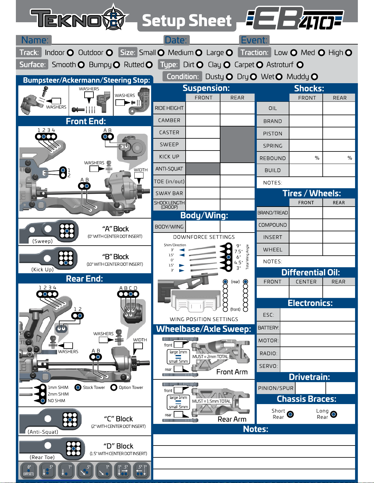
Box Setup (starting point)
18mm
1
4
2
1
0
2
0
0
21mm
-2°
15°
0°
10.5°
1.5° out
(per side) (per side)
none
78
1
1
1
.5
1.5° in
2°
1.7mm
88
STOCKSTOCK
15K 15K
500 500
Stock Stock
1.7 1.8
Yellow Yellow
5 5
Emul Emul
7K
81
-2°
Suspension:
FRONT
CAMBER
SWEEP
KICK UP
CASTER
ANTI-SQUAT
SWAY BAR
(Sweep)
(Rear Toe)
(Anti-Squat)
TOE (in/out)
(Kick Up)
RIDE HEIGHT
BODY/WING
DOWNFORCE SETTINGS
WING POSITION SETTINGS
REAR
CENTERFRONT REAR
Setup Sheet
Name: Date: Event:
Track: Size:
Shocks:
Front End:
Rear End:
Outdoor
FRONT
OIL
PISTON
BRAND
SPRING
REBOUND
BUILD
% %
SHOCK LENGTH
(DROOP)
REAR
Dierential Oil:
Electronics:
FRONT
COMPOUND
INSERT
ESC:
BATTERY:
MOTOR:
RADIO:
SERVO:
WHEEL
NOTES:
NOTES:
BRAND/TREAD
REAR
PINION/SPUR
43
21
43
21
DCBA
A
B
A B
A B
Indoor
1
2
1 2
Short
Rear
Long
Rear
Wheelbase/Axle Sweep:
Notes:
Chassis Braces:
Body/Wing:
Drivetrain:
large 1mm
(rear)
(front)
small .5mm
Bumpsteer/Ackermann/Steering Stop:
Tires / Wheels:
Small Traction: Low Med High
Surface: Type:Smooth Bumpy Rutted Dirt
Condition: Dusty Dry Wet Muddy
Clay Carpet Astroturf
LargeMedium
9
°
7.5
°
6
°
4.5
°
3
°
.5
°
0
°
(OFFSET)
.5
°
.5
°
1
°
1°1
°
.5°1
°
(0° WITH CENTER DOT INSERT)
“A” Block
(10° WITH CENTER DOT INSERT)
“B” Block
3°
Shim/Direction
Total Wing Angle
1.5°
0°
1.5°
3°
(2° WITH CENTER DOT INSERT)
“C” Block
Front Arm
Rear Arm
(1.5° WITH CENTER DOT INSERT)
MUST = 2mm TOTAL
large 1mm
small .5mm
MUST = 1.5mm TOTAL
“D” Block
WASHERS
WASHERS
1mm SHIM
NO SHIM
2mm SHIM
Stock Tower Option Tower
WASHERS
WASHERS
WIDTH
WIDTH
WASHERS
WASHERS
front
rear
front
rear
Page 31
Page 32

Tekno RC
10755 Scripps Poway Pkwy #598
San Diego CA 92131
USA
 Loading...