


2016
TFP-40x Series
Conventional Fire Alarm Panel
Installation & Operation Manual
Issue Date: 26/12/2016 Rev:02

TFP-40x Series Conventional Fire Alarm Panels
TFP-40X INSTALLATION & OPERATION MANUAL
1
Table of Contents
1 Introduction ........................................................................................................................................ 3
2 Warnings ............................................................................................................................................ 3
3 Technical Specifications ........................................................................................................................ 4
4 TFP-40x Series Conventional System ..................................................................................................... 5
4.1 Panel Properties ........................................................................................................................... 5
4.2 Panel User Interface ..................................................................................................................... 6
5 Installation .......................................................................................................................................... 9
5.1 Recommended Cables .................................................................................................................. 9
5.2 Mounting..................................................................................................................................... 9
5.3 Supply Input................................................................................................................................ 9
5.4 Battery Connection ....................................................................................................................... 9
5.7 Zone Lines ............................................................................................................................... 10
6 User Levels........................................................................................................................................ 11
6.1 Level 1 ..................................................................................................................................... 11
6.2 Level 2 ..................................................................................................................................... 11
6.3 Level 3 ..................................................................................................................................... 11
6.4 Level 4 ..................................................................................................................................... 11
7 Using the Panel ................................................................................................................................. 12
7.1 Disable Mode ............................................................................................................................. 12
7.2 Test Mode ................................................................................................................................. 12
7.3 Siren Resound Option ................................................................................................................. 13
7.4 System Error ............................................................................................................................. 13
7.5 Error Diagnostic ......................................................................................................................... 13
8 Maintenance ...................................................................................................................................... 14
8.1 Situations requiring Maintenance, Repair or Servicing .................................................................... 14
8.2 Routine Checks .......................................................................................................................... 14
8.2.1 Daily ..................................................................................................................................... 14
8.2.2 Weekly .................................................................................................................................. 14
8.2.3 4 Years ................................................................................................................................. 14
9 Appendices ........................................................................................................................................ 15
9.1 Appendix-Mechanical .................................................................................................................. 15
9.2 Appendeix- Electrical .................................................................................................................. 19
9.3 Appendix-Level .......................................................................................................................... 21
10 Issues to be considered ...................................................................................................................... 26
10.1 Maintenance, Repair and Cleaning to be carried out by the Consumer ............................................ 26
10.2 Information on Faulty Usage ....................................................................................................... 26
10.3 Handling and Transportation ....................................................................................................... 26
TFP-40x Series Conventional Fire Alarm Panels
TFP-40X INSTALLATION & OPERATION MANUAL
2
Table 1 Main Button Functions ...................................................................................................................... 7
Table 2 Auxiliary Button Functions ................................................................................................................. 8
Table 3 Level-2 Key...................................................................................................................................... 8
Table 4 LED Indicators ................................................................................................................................. 9
Table 5 Properties of the Recommended Cables ........................................................................................... 10
Table 6 Known Errors ................................................................................................................................. 14
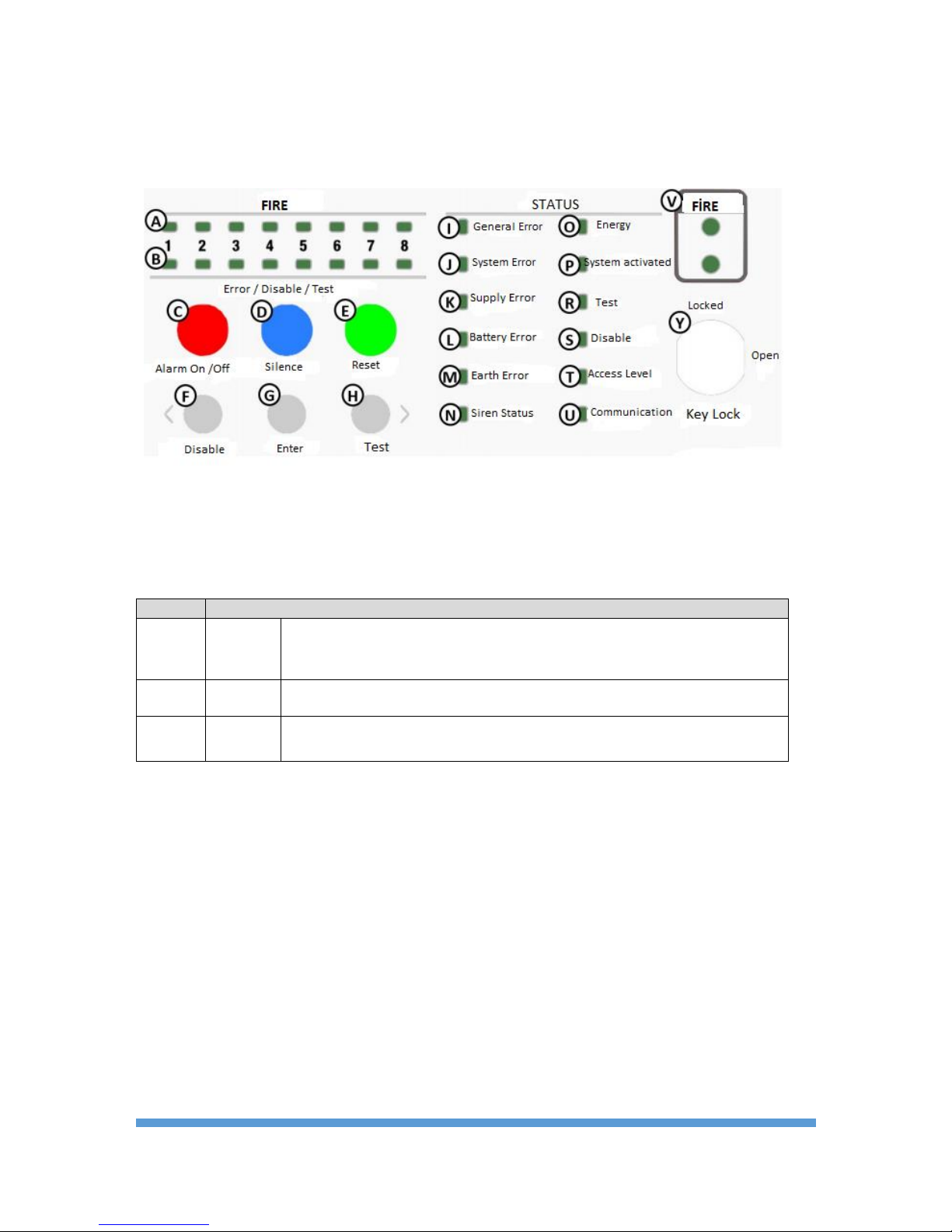
Figure 1 Control Panel User Interface ............................................................................................................ 7
Figure 2 Panel Front Cover Screws .............................................................................................................. 16
Figure 3 Mounting Screw Holes ................................................................................................................... 17
Figure 4 Electrical Connections .................................................................................................................... 18
Figure 5 Battery Connection ........................................................................................................................ 19
Figure 6 Siren Connection ........................................................................................................................... 20
Figure 7 Zone Connection ........................................................................................................................... 20
Figure 8 Zone Grounding Connection ........................................................................................................... 21
Figure 9 Level-3 ......................................................................................................................................... 22
1922
Bilgi Elektronik San. ve Tic. A.Ş.
Dudullu OSB 1. Cad. İsmet Tarman İş Merkezi
No:1 Kat:2/32 Ümraniye, İstanbul, Turkiye
16
1922-CPD-0690
EN 54-2:1997, EN 54-2:1997/AC:1999, EN 54-2:1997/A1:2006
Control and indicating equipment for fire detection and fire alarm systems for
buildings
TFP-404, TFP-408
Provided options:
Output to C
Test Condition
EN 54-4:1997, EN 54-4:1997/AC:1999, EN 54-4:1997/A1:2002, EN 54-4:1997/A2:2006
Power supply equipment for fire detection and fire alarm systems for buildings
TFP-404, TFP-408
Other technical data: see BİLGİ-TEC-160928 held by the manufacturer.

TFP-40x Series Conventional Fire Alarm Panels
TFP-40X INSTALLATION & OPERATION MANUAL
3
1 Introduction
This manual contains the installation instructions, technical properties, and panel configuration information
related to TFP-40x Series Teknim Conventional Panels.
TFP-40x Teknim conventional panels may be viewed under 2 options as 4- or 8-zone devices. 32 detectors or
fire alarm buttons can be connected per zone.
TFP -40x series panels compliant with EN54-2/4 standards
Before installation, the manual must be read and installation must be carried out by authorized
persons in accordance with the instructions.
Before starting the installation, check that the following list is complete inside the package:
- TFP-40x panel,
- 6 pieces of 4K7 siren end-of-line resistances for TFP-404 and 10 pieces for TFP-408,
- Lock key for access level 2,
- Battery cable,
- Battery mounting lugs and 4 screws
- 4 screws and dowels for wall-mounting
- Allen key,
- Installation and Operation Manual
- Quick Installation Manual
- Warranty Certificate
2 Warnings
- The panel contains electronic card consisting of digital and analog circuits. Therefore it should not be
used before having read the entire operation manual.
- In case of any malfunction or in the case that the panel needs maintenance, maintenance and repairs
must be carried out by the authorized service station of the manufacturer company or the people/companies
authorized by the manufacturer company.
- The cable lines for the supply line of the panel, siren line, and the detector line should be as specified in
this manual.
- When panel is energized with supply voltage, do not make any changes to the panel connections.
- The grounding connection to the panel must have been made.
- Do not apply ~230 VAC 50Hz mains voltage to the inputs-outputs of the zone line, inputs of the siren
line connections, and the inputs of the battery connections.
- Do not use batteries that have reached the end of useful life or have been damaged by falling below a
voltage level. The device does not charge batteries that are below voltage level 20.5 VDC.
Warning: Do not start mounting before having read the entire manual.

TFP-40x Series Conventional Fire Alarm Panels
TFP-40X INSTALLATION & OPERATION MANUAL
4
3 Technical Specifications
Supply
Voltage
230 / 110 VAC (+%10 / -%15)
Frequency
50 / 60 Hz (±%5)
Mains Input Fuse
2A
Output Voltage
21 – 29 Vdc ± %2
Output Fuse
4A (F1)
Cable Type
3 x 1,5mm² (Phase, Neutria, Ground)
Battery
2 x 12V, 7Ah (Recommended Yuasa NP7-12, 12V7Ah)
Battery CutOff Voltage
20,5 V
Battery Internal Resistance Fault
Resistance > 1,5 ohm
Greatest Current to be drawn from the
Battery
When the main power source is not connected 2A
Battery Fuse
4A (F2)
Charging Voltage
27,6 Vdc @20°C, with heat compensation
Charging Current
500mA (resistance limited)
Imin
TFP-404 – 75mA, TFP-408 – 110mA
ImaxA
500 mA
ImaxB
1,5 A
Outputs
Supervised Siren Outputs
2 adet 24Vdc (15 devices / 32mA per device)
(Caution : The output current of the panel should not exceed 1.4 A)
Siren Fuse
2 x 500mA (F5-F6)
Siren End-of-line Resistance
4K7 ohm, %5, 1/4W
General Error Relay
1 x NC/NO dry contact 30V, 2A
Fire Relay
1 x NC/NO dry contact, 30V, 2A
Auxiliary Output (AUX)
1 x 24Vdc/450mA(Caution : The output current of the panel should not exceed 1.4
A)
AUX Fuse
1 x 500mA (F3)
Cable Type for Outputs
2 x 1,5mm² J-Y(St)Y…Lg (Recommended)
Zone Information
Number Of Zones
4 or 8
Number of Detectors
32 pieces per zone (TFD series)
Output
24Vdc/450mA(Caution : The output current of the panel should not exceed 1.4A)
Output Fuse
1 x 500mA (F4)
Cable Resistance
40 ohm (en fazla)
Cable Length
1,5 km 1,5mm² cross-section (Maximum)
End Of Line Resistance
4K7 ohm, %5, 1/4W
Cable Type For zone
2 x 1,5mm² J-Y(St)Y…Lg (Recommended)
Environmental Conditions
Temperature
-10C ~ 55C (14F ~ 131F)
Humidity
95% RH (maximum)
IP Class
IP30
Mechanical
Color
RAL9006(Light Gray)
Dimensions (H x W x D)
340 x 300 x 100 mm
Weight
4,4kg (without battery)
• The device properties may be changed without notification.
• The battery recommended for the device is Yuasa NP7-12.
• The greatest current that can be given to the zones and outputs is 1.4A.

TFP-40x Series Conventional Fire Alarm Panels
TFP-40X INSTALLATION & OPERATION MANUAL
5
4 TFP-40x Series Conventional System
TFP-40x series conventional systems are fire detection systems, which are designed with 4 or 8-zones and in
which 32 detectors or fire alarm buttons can be connected per zone. The system also provides features like 2
supervised siren outputs, 1 dry contact fault relay, 1 dry contact alarm relay, and 1 x 24 AV AUX output.
The panels satisfy the standards "EN54-2 & 4 Fire detection and fire alarm systems - Control and indicating
equipment". In addition, they satisfy the following conditional provisions of EN54-2:
- EN54-2 Article 7.8. Transmission of fire alarm signals received from one zone to fire alarm devices,
- EN54-2 Article 10. Test status that allows automatic resetting for zone fire test;
The panels are supplied by 2-ampere internal power supply. Spaces have been allocated in the panels for
placement of batteries as shown in "Figure 5 Battery Connection". The power supply compliant with EN54-4 has a
smart battery charging system with heat compensation.
The transition between access levels 1 and 2 is facilitated with the switch at the front of the panel. For access
level 3, the front cover of the panel must be removed. Access level 4 is made available with a special apparatus
provided by the manufacturer.
There are 6 buttons to control the system. 3 performance these, "Alarm On/Off", "Silence" and "Reset", are
designed larger and in color to direct the user.
For the calculation of how long the system can be supplied via a battery after an interruption of the main supply,
the current consumptions of the panel are given in the table for uncharged and alarm statuses.
Model
Idle Status
Alarm Status
TFP-404
75 mA
140 mA
TFP-408
115 mA
180 mA
4.1 Panel Properties
• 4 or 8 zones controlled against incorrect connections with end-of-line resistances,
• Capability to connect 32 detectors or fire alarm buttons per zone,
• "Fire and Fault/Disable/Test" LEDs for the zones,
• LEDs for general error, system error, supply error, battery error , earth error , siren status, energy, system
on , test, disable , access level, communication, general alarm,
• Capability to disable desired zones; capability to see the disabled zones with the dedicated disable LED on
the panel.
• Easily conducted zone test,
• Smart charging system that prolongs the battery life; where there is no main supply and the system is
supplied through battery, when the battery voltage drops below 20.5 VDC, the device shuts itself down
automatically to preserve the batteries and not to cause false alarms.
• 2 siren outputs controlled against incorrect connections with end-of-line resistances,
• 1 NC/NO fire relay (button alarm, detector alarm, etc.)
• 1 NC/NO fault relay (Energy error , zone error , battery error , etc.)
• 1 output with Aux 24VDC 500 mA automatic fuse
• Switch system determining intervention authorization level
• Easy-to-understand front panel,
• Switched power supply (with 27.75 Vdc SMPS 2A automatic fuse)
• Metal housing
• Used with 2 x 12V 7Ah batteries. The battery recommended for the device is Yuasa NP7-12
TFP-40x Series Conventional Fire Alarm Panels
TFP-40X INSTALLATION & OPERATION MANUAL
6
4.2 Panel User Interface
This chapter describes the indicators and buttons on the panel.
Figure 1 Control Panel User Interface
The buttons C, D, and E shown in Figure 1 Control Panel User Interface are main buttons and have single
functions. They are designed larger than other buttons and in color for user convenience. The functions of the
buttons are defined in Table-1.
Table 1 Main Button Functions
Label
Task
[C]
ALARM
On / Off
Shall be used in Level-2 and Level-3.
Starts the evacuation procedure, activates sirens.
Mutes sirens in alarm status or resounds the muted sirens.
[D]
MUTE
Mutes Buzzer in cases of fault or alarm.
[E]
RESET
Shall be used in Level-2 and Level-3.
Used to restore the panel in alarm or fault status to normal operating status.
The buttons F, G, and H shown in Figure 1 Control Panel User Interface have multiple functions. These functions
vary depending on the access level and the time of button presses.
The functions of the buttons are defined in Table-2.
Long press: Keeping the button pressed for more than 3 seconds
Short press: Pressing and releasing the button in a period under 3 seconds

TFP-40x Series Conventional Fire Alarm Panels
TFP-40X INSTALLATION & OPERATION MANUAL
7
Table 1 Auxiliary Buttons Functions
Label
Task
Short press
Long press
[F]
DISABLE
(<)
It is used to change the processed zone
when test or disable process is active in
Level-2. It shows the disable zones for
3 seconds when Level-1 and test or
disable process are deactivated.
It is used to turn on and off the
deactivation process in Level-2. In this
case, the fault statuses of the zones or
the siren are not shown. Only the disable
zones are shown.
[G]
ENTER
It is confirmed to carry out disable or
test processes at the selected
zone/siren when disable or test
processes are carried out.
It is used to show the details of the fault
statuses in Level-1.
[H]
TEST (>)
It is used to test the buzzer and the
LEDs in Level-1.
It is used to change the processed zone
or siren when disable process is active
in Level-2. Also, it is used to show the
tested zones and siren for 3 seconds
when test and disable processes are
deactivated.
It is used to show the zones and siren
being tested for 3 seconds in Level-1.
It is used to turn on and off the test
process in Level-2. In this case, it show
the zones and siren being tested.
Level 1 and 2 checks are carried out with a special key provided by the manufacturer company. It is not possible
to remove the key in Level 2.
Table 3 Level - 2 Key
Label
Task
[Y]
LEVEL-2
Key in vertical position; Keylock off; Level-1
Key in horizontal position; Keylock on; Level-2
Panel fault and alarm statuses are provided with LED indicators. An internal buzzer is available to provide audible
warning. LEDs and buzzer can be tested without transiting to any level.

TFP-40x Series Conventional Fire Alarm Panels
TFP-40X INSTALLATION & OPERATION MANUAL
8
Table 4 LED Indicators
Label
LED name
Fixed LED
Blinking LED
Color
[V]
FIRE
NONE
Shows that the panel is in alarm
status (250 ms)
Red
[I]
General Error
Shows a system error
Shows there is a fault in the
system
Yellow
[J]
System Error
Shows a system error
NONE
Yellow
[K]
Supply Error
NONE
Shows there is a fault in the
power source or charging circuit
Yellow
[L]
Battery Error
NONE
Shows there is a fault in the
battery
Yellow
[M]
Earth Error
NONE
Shows there is a fault in the
earth connection
Yellow
[N]
Siren Status
Shows that the siren is
disabled
Shows there is a fault in the
siren
Yellow
[O]
Energy
Shows that the system is
supplied from any source
NONE
Green
[P]
System
Activated
Shows that there no problems
that can affect the full
operation of the system
NONE
Green
[R]
Test
Shows that one or more
zones are in test status
NONE
Yellow
[S]
Disable
Shows that the zones or the
siren are disabled
NONE
Yellow
[T]
Access Level
Level 3 active
Level 2 active
Yellow
[U]
Communication
NONE
Show that the system is
communicating with the
computer
Yellow
[A]
Zone fire
NONE
Shows that the zone is in fire
status
Red
[B]
Zone
Fault/Disable
/Test
Shows that the zone is
disabled or in test status
Shows there is a fault in the
zone
Yellow

TFP-40x Series Conventional Fire Alarm Panels
TFP-40X INSTALLATION & OPERATION MANUAL
9
5 Installation
This chapter describes the mechanical and electrical connection methods for TFP-40x series panels.
Caution: Do not start mounting before having read the entire manual!
5.1 Recommended Cables
It is recommended that cables with the properties described in "Table 5 Properties of the Recommended Cables"
are used with the cabling installations and in all the electrical connections.
Table 5 Properties of the Recommended Cables
Cable
Cable Property
Maximum
Supply
3 x 1,5mm²
N/A
Zone Lines
1x2x0,8+0,8JY(st)Y
1x2x1,5+1,5J-Y(st)Y
0 – 500 metre
500 – 1500 metre
Siren Lines
1x2x0,8+0,8JY(st)Y
1x2x1,5+1,5J-Y(st)Y
0 – 500 metre
500 – 1500 metre
5.2 Mounting
For mounting, one should select a clean and dry area, which is easily accessible by the user, where the panel is
not subjected to jolts and vibrations. The panel should be placed on a level surface at the eye level and it should
not be placed in another cabinet or someplace close to heat sources. There are cable inlets from the top and rear
for mounting convenience.
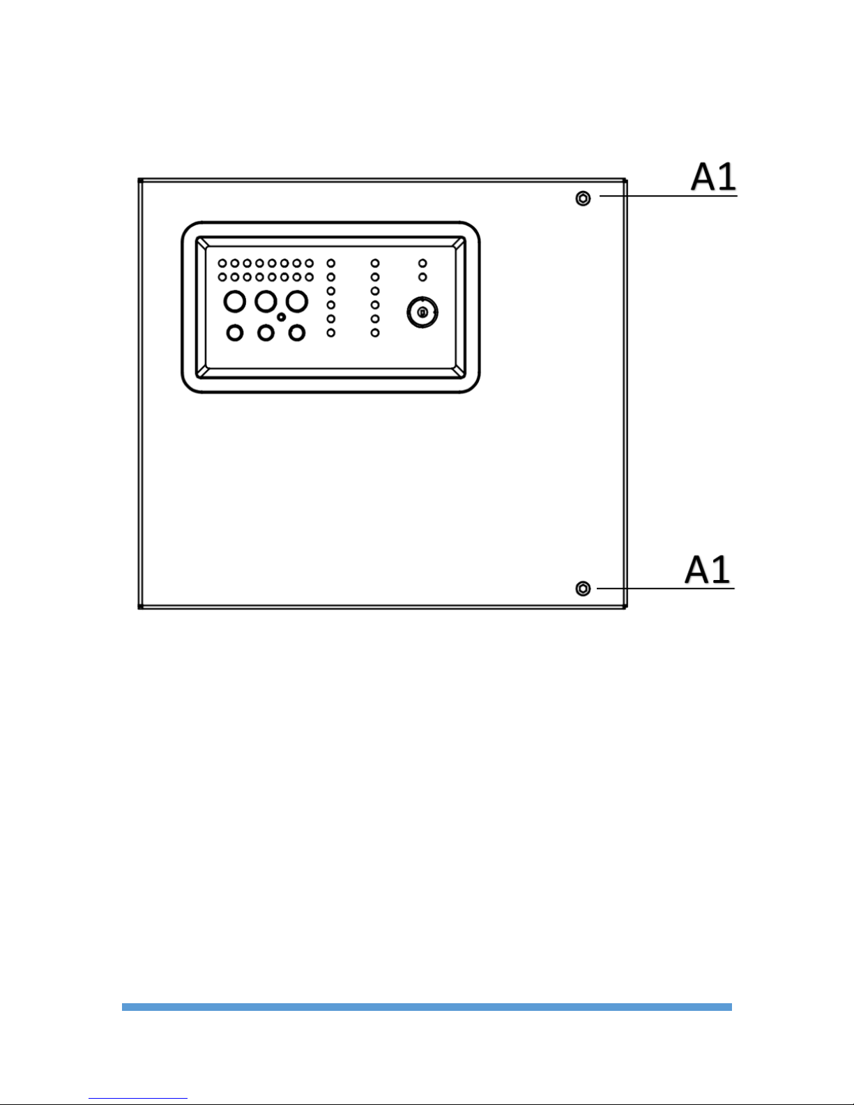
1 Loosen the A1 screws shown in "9.1 Appendix-Mechanical / Figure 2 Panel Front Cover Screws" with the
Allen key provided with the device.
2 Using the panel as the template, mark the wall from the A2 screw holes shown in "9.1 Appendix-Mechanical
/ Figure 3 Mounting Screw Holes".
3 Drill the holes marked on the wall and complete the fixing process with minimum 4-mm dowel and screws.
4 Then proceed to battery and cable connection processes.
5.3 Supply Input
The panel main supply input should be connected to the 195~250 VAC 50 Hz mains voltage and earth connection
must be made. It should be ensured that grounding resistance is less than 10 ohms. The main supply input fuse
of the panel must be 2A. Also, the panel supply cable must be of the type 3x1.5 NYM or 3x1.5 NYA. The electrical
connection should be made in accordance with the tag as shown in "9.1 Appendix-Mechanical / Figure 4 Electrical
Connections".
WARNING!
Do not remove or connect any connections when the system is energized.
WARNING!
This device should not be used without appropriate grounding
5.4 Battery Connection
The panel is supplied with 2 x 12V 7Ah sealed lead acid batteries and should be used with batteries of this kind.
For the battery mounting, the posts should be placed facing each other as shown in "9.1 Appendix-Mechanical /
Figure 5 Battery Connection" and the battery rails shown as B1 should be fixed tightly with screws.
For the battery mounting, the ends shown as B3 and B4 are connected to each other with battery jumper cable
as shown in "9.1 Appendix-Mechanical / Figure 5 Battery Connection" and the battery rails shown as B4 should be
fixed tightly with screws. Then the ends shown with B2 and B3 are connected to the battery supply socket with
battery supply cable.
System used the main supply as the primary power supply. Smart charging circuits are designed to keep batteries
always at full capacity.

TFP-40x Series Conventional Fire Alarm Panels
TFP-40X INSTALLATION & OPERATION MANUAL
10
In the case that main supply is interrupted, the smart charging unit automatically opens the battery connections
and shut down the system to prolong the useful lifetime of the batteries when the battery voltage drops below
20.5V. If the main supply is restored, the batteries automatically return to charging status.
5.5 Battery Charge Voltage Check
Battery charge voltage is set at the factory as 27.6 VDC at 20°C. Therefore there is no need to readjust the
battery charge voltage. But if problems occur with battery charge, the following steps should be taken:
1 After the battery is disconnected and the panel displays the error "No Battery", no voltage should be seen at
the battery connector of the panel.
2 The front cover of the panel should be opened and device shall be taken to Access Level-3. At this level,
heat compensation of the smart charging system is deactivated.
3 The output voltage of the main supply should be checked. In this case the output voltage should be 27.75
±50mV. If the output voltage is not at this level, the output voltage should be brought to this level via the
adjustment potentiometer located near the power supply.
4 When the adjustment of the output voltage of the power supply is completed, the panel should be brought
back to access level-1.
5 When an empty battery (~22V) is reconnected to the panel, it must be seen that voltage between the
battery poles rise rapidly. If not, there is a problem with the battery or the panel.
5.6 Inputs and Outputs
Relay Outputs: The panel has 2 dry-contact relay output that can withstand a current of 2A at 30 VDC. These
dry-contact relays are fire relay (normally non-energized) and fault relay (normally energized).
Important Note: The relays of the fire alarm panel are signal relays. If these relays are to operate a device
as command relays, a contactor should be place in between. If a contactor is not used when the relay outputs
are used in an application that draws high current, then the panel may be damaged and this situation is
outside the warranty scope.
Siren Outputs: The panel has 2 siren outputs of 24 V DC 500 mA with automatic return and fuse protection.
Drawing too much current through this output causes to panel to give out faults. This output is monitored by the
end-of-line resistance against open circuits and short circuits. The cable of the siren supply line must a 2x1.5mm2 cable. The connections are shown in "9.2 Appendix-Electrical / Figure 6 Siren Connection.
Alarm Relay: In case of a fire alarm from the detection zones or when the "Alarm On /Off " button on the front
of the panel is pressed, it is activated by changing contacts and is used to control another system. In order for
the active relay to be restored, the fire status has to be eliminated and the "Reset" button on the panel has to be
pressed.
Trouble Relay: It is activated by changing contacts in case of a fault alert from the system and when the power
is not supplied to the panel. Trouble relay automatically returns to its previous position with the elimination of the
fault status.
AUX Output (External Supply Output): The panel has 24VDC 500mA external supply output with automatic
fuse protection. In cases of blackouts, the external supply output is supplied until the battery reaches the cutoff
voltage.
5.7 Zone Lines
TFP-40x Teknim conventional panels may be viewed under 2 options as 4- or 8-zone devices. Detection circuits
provide power (24 VDC) to the detectors and buttons and at the same time ensures that signals like fire alarm,
short circuit, and broken line are transmitted to the panel Maximum 32 detectors or alarm buttons can be
connected to a zone line. Cable coded 1x2x0,8+0,8JY(st)Y should be used for connection distances of 0 - 500
meters and cable coded 1x2x1,5+1,5J-Y(st)Y for connection distances of 500 - 1500 meters.
The form of connection of the zone line with the detector and alarm button is shown in "Appendix-Electrical /
Figure 7 Zone Connection". Unused zones should be disabled over the panel or terminated with the termination
resistance. If no connections are made to the zone, the panel gives the error "Zone Open Circuit".
Zone cables should be kept away from high-voltage cables that may cause interference at the site and from
strong magnetic fields. Earthing of the signal cables must absolutely be made from the earthing bar inside the
panel as shown "Figure 8 Zone Grounding Connection".

TFP-40x Series Conventional Fire Alarm Panels
TFP-40X INSTALLATION & OPERATION MANUAL
11
6 User Levels
Some features of the panel are restricted with user levels and the panel has 4 user levels.
6.1 Level 1
Level 1 is defined as the predefined user level with the most basic features. When the key lock is off (key in
vertical position), Level-1 is entered. The authorizations of the Level 1 user are shown in the following list:
• Indicators and Buzzer Test;
• Buzzer muting,
• Displaying disabled zones or sirens,
• Displaying the zones being tested,
• Detail fault display,
6.2 Level 2
Level 2 is the level that the authorized person with the system control authorization may enter using the key
provided with the panel. When the key lock is on (key in horizontal position), Level-2 is entered. The
authorizations of the Level 2 user are shown in the following list:
• Level-1 authorizations,
• Deactivating and activating zones/sirens,
• Zone test,
• Evacuation status creation,
• Muting or reactivating sirens in an alarm situation,
• Resetting alarm or fault statuses
To leave Level-2, turn the key into vertical position and remove it.
6.3 Level 3
All the authorizations and functions of the system can be performed at this level. The users of this system are
authorized persons who have received training on system installation and maintenance. To enter Level-3, first the
front cover of the panel should be removed and "Access Level-1 Activation Switch" shown in "9.3 Appendix-Level
/Figure 9 Level-3" should be brought to "ON" position.
The authorizations of the Level 3 user are shown in the following list:
To leave Level-3, turn the switch into the original position.
• Level-2 authorizations,
• Option to reactivate the sirens for every new fire situation,
• Computer connection (to monitor panel data),
• Hard Reset,
6.4 Level 4
Level-4 can be entered via a special apparatus provided by the manufacturer. At this level the user can change
the memory where the user program is located and the working data of the site.

TFP-40x Series Conventional Fire Alarm Panels
TFP-40X INSTALLATION & OPERATION MANUAL
12
7 Using the Panel
In this chapter, information on using the panel is given.
7.1 Disable Mode
Disable mode is used to isolate an unused zone or siren from the system.
Disable mode settings can be adjusted from access levels-2, 3 and 4.
In order to deactivate a zone or a siren, "Disable" button is pressed for some time. The panel opens the disabling
setting after 3 s. "Disable" LED and "Zone-1 Fault/Disable /Test" LED begin to flash. This shows that the panel
has started the disabling process and Zone-1 is in selection mode.
The zone or siren to be selected is changed by pressing "Disable (<)" or "Test (<)" keys. When the zone or siren
to be disabled is reached, if "Enter" is pressed again, the selected zone starts flashing rapidly. When "Enter" is
pressed again, the selected zone starts blinking slowly. Rapid flashing of the selected zone's LED shows that the
zone is disabled and slow flashing, then turning off shows that the zone is active.
After the desired zones or sirens are disabled, "Disable" button is pressed again for some time and disabling
process is shut down. If a zone or a siren is disabled, "Disable" LED lights up constantly. Otherwise, "Disable" LED
turns off.
When the deactivation process is turned on, the faults and test statuses of the zones and sirens are not displayed
so as not to cause any confusion. Only the deactivated status is shown.
In order for the user to distinguish between test and disabling statuses, when the "Disable" button is pressed for
some time at access level-1, the panel shows for 3 s only the disabled zones.
7.2 Test Mode
The test mode is used so that the testing of the fire detection system can be conducted by a single person. When
a fire signal is received from the detectors or fire alarm buttons from a zone being tested, the panel enters into
fire status. If sirens are selected in the test mode, the panel activates also the panel outputs and resets itself
after 10 s.
Test mode settings can be adjusted from access levels-2, 3 and 4.
In order to test a zone or a siren, "Test" button is pressed for some time. The panel opens the test operation
after 3 s. "Test" LED and "Zone-1 Fault/Disable/Test" LED begin to flash. This shows that the panel has started
the test setting process and Zone-1 is in selection mode.
The zone or siren to be selected is changed by pressing "Disable (<)" or "Test (<)" keys. When the zone or siren
to be tested is reached, if "Enter" is pressed again, the selected zone starts flashing rapidly. When "Enter" is
pressed again, the selected zone starts blinking slowly. Rapid flashing of the selected zone's LED shows that the
zone is under test and slow flashing shows that the zone is not being tested.
If it is desired for the sirens to be active during zone test, the sirens have to be selected together with the zone.
After the desired zones or sirens are taken into test mode, "Test" button is pressed again for some time and test
mode setting process is shut down. If a zone or a siren is in test mode, "Test" LED lights up constantly.
Otherwise, "Test" LED turns off.
When the test process is turned on, the faults and disabled statuses of the zones and sirens are not displayed so
as not to cause any confusion. Only the test status is displayed.
In order for the user to distinguish between test and disabled statuses, when the "Test" button is pressed for
some time at access level-1, the panel shows for 3 s only the zones being tested.
If no alarm comes from the tested zone for a period of 1 hour, then panel automatically takes the tested zone out
of the test mode.
TFP-40x Series Conventional Fire Alarm Panels
TFP-40X INSTALLATION & OPERATION MANUAL
13
7.3 Siren Resound Option
As a default setting, when the panel first enters into fire status and the sirens are muted with the "Arm/Disarm"
button, if an alarm is detected from another zone, siren are automatically activated.
This can be changed as an option. If changed, sirens will not be reactivated for each new alarm detected after
the sirens are muted with the "Alarm On/Off" button.
To adjust this setting;
1 Enter Access Level-3.
2 Bring the "Siren Resound Option Switch" shown in "9.3 Appendix-Level /Figure 9 Level-3" to "ON"
position.
3 Restore access level to 1.
7.4 System Error
TFP-40x Teknim conventional panels are microcontroller-based systems. As per EN54-2 Article 13.3, the
microcontroller is controlled by another completely independent system. In the case that the microcontroller fails
to carry out program flow for any reason, the panel automatically takes itself into secure status. In this case, the
following occur:
1 General Error and System Error LEDs light up constantly. System On LED turns off.
2 Buzzer rings constantly. The buzzer can be silenced using the "Mute" button.
3 Energy to the zones and sirens is disconnected so as not to cause any false detection.
4 Trouble relay is activated.
WARNING!
In case of a system error, contact your dealer or authorized service station.
7.5 Error Diagnostic
In case of a fault, "General Error" LED and the related fault LED flashes. Situations detected as faults are given in
Table 6.
Table 6 Recognized Errors
LED name
Errors that may occur
General Error
Any faults
System Error
If the microcontroller is not operational for any reason
If the system voltage is below 14V
Supply Error
If there is no main power supply
If the battery charging circuit is faulty
Battery Error
If there is no battery
If the battery is empty
If the battery internal resistance is greater than 1.5 ohms
Earth Error
If the earth voltage is high
If the earth voltage is low
Siren Status
If the siren is open-circuited
If the siren is short-circuited
Zone
Error/Disable/Test
If the zone is open-circuited
If the zone is short-circuited
Open-circuit or short-circuit faults of the zones that might occur in installation is shown in more detail by the
panel for the convenience of the installer.
When the "Enter" button is pressed, the panel shows the details of the zone faults in more detail for 3 seconds.
During these 3 seconds, if the fault LED lights up constantly the zone is short-circuited and if it flashes the zone is
open-circuited.

TFP-40x Series Conventional Fire Alarm Panels
TFP-40X INSTALLATION & OPERATION MANUAL
14
8 Maintenance
Maintenance and repair on Teknim TFP-40x series fire systems should be carried out by authorize people in
accordance with the instructions.
8.1 Situations requiring Maintenance, Repair or Servicing
In case of malfunction or in the following situations, contact your dealer or authorized service station.
• If the power cable or wire is damaged,
• If any liquid penetrates into the device or an object falls inside,
• If it is exposed to water or rain,
• If the device is dropped or the housing is damaged
• If there are noticeable performance changes in the device.
• If the device does not operate normally in line with the operating instructions in the operation manual,
call the service station because faulty interventions may cause other malfunctions.
WARNING!
Do not attempt to repair the device. You may be subjected to electrical shock when you open the
cover of the device. In case of malfunction, contact your dealer or authorized service station.
Only qualified and authorized servicing personnel should carry out technical interventions on the
device. The device should be cleaned with a dry cloth. No chemicals should be used
8.2 Routine Checks
8.2.1 Daily
The authorized person should check the device daily for any fault statuses. The green "Energy" and "System On"
LEDs on the panel should be lit.
8.2.2 Weekly
Fire alarm systems should be tested weekly.
Each week, a normally operational alarm button should be activated weekly and it should be noted if there are
any problems in the fire detection and warning system of the panel.
The tests should be conducted on the same day of the week and a different alarm button shall be used for each
test. Test results should be kept under record.
After the test is completed, the activated alarm button should be returned to its original status.
Important Note: Before testing the fire alarm system , auxiliary outputs should be isolated from the system.
8.2.3 4 Years
TFP-40x series conventional fire detection panels contain 2 sealed lead acid batteries as a redundant power
supply against an interruption of the main supply. The average lifetime of these batteries is 4 years. Batteries
should be replaced after this period.
TFP-40x Series Conventional Fire Alarm Panels
TFP-40X INSTALLATION & OPERATION MANUAL
15
9 Appendices
The Appendices are divided into 4 categories a Mechanical, Electrical, Level and Maintenance Tables.
9.1 Appendix-Mechanical
Figure 2 Panel Front Cover Screws

TFP-40x Series Conventional Fire Alarm Panels
TFP-40X INSTALLATION & OPERATION MANUAL
16
Figure 3 Mounting Screw Holes
A2 Mounting Screw Hole

TFP-40x Series Conventional Fire Alarm Panels
TFP-40X INSTALLATION & OPERATION MANUAL
17
Figure 4 Electrical Connections
A3 Battery Connection Connector
A4 Main Supply Connection Connector
A5 Main Supply Voltage Adjustment Potentiometer
A6 Button for Startup from Battery
A7 Mains Fuse

TFP-40x Series Conventional Fire Alarm Panels
TFP-40X INSTALLATION & OPERATION MANUAL
18
Figure 5 Battery Connection
• Batteries are placed in the area shown as B6.
• Battery rails shown as B1 are fixed with screws.
• B4 and B5 are connected to each other with jumper cable.
• B2 and B3 are connected to the battery supply socket with battery supply cable.
• Do not use batteries that have reached the end of useful life or have been damaged by falling
below a voltage level. The device does not charge batteries that are below voltage level 20.5
VDC.

TFP-40x Series Conventional Fire Alarm Panels
TFP-40X INSTALLATION & OPERATION MANUAL
19
9.2 Appendix- Electrical
Figure 6 Siren Connection
Figure 7 Zone Connection

TFP-40x Series Conventional Fire Alarm Panels
TFP-40X INSTALLATION & OPERATION MANUAL
20
Figure 8 Zone Earth Connections

TFP-40x Series Conventional Fire Alarm Panels
TFP-40X INSTALLATION & OPERATION MANUAL
21
9.3 Appendix-Level
Şekil 1 Seviye-3
C1 Computer Communication Connector
C2 Switch for Siren Resound Option
C3 Access Level-3 Activation Key
C4 Hardware Reset

TFP-40x Series Conventional Fire Alarm Panels
TFP-40X INSTALLATION & OPERATION MANUAL
22
9.4 Appendix-Maintenance Table
Date
Tested Device
Device Position
Remarks

TFP-40x Series Conventional Fire Alarm Panels
TFP-40X INSTALLATION & OPERATION MANUAL
23
Date
Tested Device
Device Position
Remarks

TFP-40x Series Conventional Fire Alarm Panels
TFP-40X INSTALLATION & OPERATION MANUAL
24
Date
Tested Device
Device Position
Remarks

TFP-40x Series Conventional Fire Alarm Panels
TFP-40X INSTALLATION & OPERATION MANUAL
25
Date
Tested Device
Device Position
Remarks

TFP-40x Series Conventional Fire Alarm Panels
TFP-40X INSTALLATION & OPERATION MANUAL
26
10 Issues to be considered
10.1 Maintenance, Repair and Cleaning to be carried out by the Consumer
There are no maintenance or repair that the consumer can perform individually. You may be subjected to
electrical shock when you open the cover of the device. The device should be cleaned with a dry cloth. No
chemicals should be used.
10.2 Information on Faulty Usage
Do not allow unauthorized people to open or to change the settings of your device. Otherwise, your device may
operate differently than it did originally.
10.3 Handling and Transportation
The device should be carried carefully so as not to subject it to any external impacts and to prevent liquid
penetration. Malfunctions arising due to improper handling are outside the scope of warranty.
* Complies with Directive 2002/96/EC. This product is produced from recyclable and reusable, high-quality parts
and materials. Therefore, do not dispose of the product together with the household or other waste at the end of
its lifetime. Please take it to a collection point for the recycling of electrical and electronic devices..
MANUFACTURER
Bilgi Elektronik Sanayi ve Ticaret A.Ş.
Dudullu OSB 1. Cadde İsmet Tarman İş Merkezi No:1 Kat:2 No:32 Ümraniye / İstanbul / Türkiye
Telephone: +90 216 455 88 46 Fax: +90 216 455 99 06
www.teknim.com www.bilgielektronik.com.tr
Technical Support: support@bilgielektronik.com.tr
Sales: sales@bilgielektronik.com.tr
 Loading...