

Page 1

READ THIS CLEARPATH QUICK START GUIDE
OR
CLICK HERE TO CONTINUE ON TO THE CLEARPATH USER MANUAL
Introduction
Congratulations on choosing a ClearPath all-in-one servo system. We know that
when most people get a new tech product, they want to try it out right away. For
that reason ClearPath is ready to go right out of the box. Your ClearPath motor was
shipped to you fully tested and factory preconfigured for unloaded use (i.e. for use
with nothing attached to the shaft). This means you can power it up, connect to your
PC, and start making test moves within minutes. And, when you’re ready to connect
ClearPath to a mechanical system, you’ll have the world’s most advanced Autotuning software to help. Use this Quick Start Guide to get up and running quickly,
but refer to the ClearPath User Manual for complete details on safety, installation,
and operation.
DC Power Connector
(Molex Minifit Jr. 4 pos.)
I/O Connector
(Molex Minifit Jr. 8 pos.)
(Anodized Aluminum)
Housing
Communication Port
(USB Micro-B)
Status LED
Auxilliary PE
(Protective Earth)
Connection Point
Sealing
Gasket
Die Cast
Heatsink
NEMA
Mounting
Flange
Keyway
Parts of a ClearPath
Stainless
Steel Shaft
Read This Warning!
Always use caution and common sense when handling motion control equipment.
Even the smallest ClearPath Motor is powerful enough to remove fingers, turn a tie
into a noose, or tear out a patch of hair and/or scalp in just a few milliseconds (by
comparison, it takes about 100 milliseconds to blink). We’re not trying to alarm you
(OK, maybe a little) but we do want all ClearPath users to stay safe
These devices are extremely powerful and dangerous if used carelessly. Please read
and understand all safety warnings in the ClearPath User Manual before operating a
ClearPath Motor.
and fully intact
.
Teknic, Inc. - 1 - ClearPath Quick Start Guide rev.2.2
Page 2

Initial Setup
Download and install ClearPath MSP (Motor Setup Program) from the Teknic website:
http://www.teknic.com/downloads
Vista.
. MSP is compatible with Windows 8, 7, XP and
Teknic website: Downloads page
Secure your ClearPath to a stable work surface. A “Quick-Grip” style bar clamp or
bench vise works well. Tip: You can help preserve your motor’s finish by covering the
vise jaws with tape.
CLAMP MOTOR
to a stable work surface.
ClearPath Motor
Clamp it!
Teknic, Inc. - 2 - ClearPath Quick Start Guide rev.2.2
Page 3

IMPORTANT! Check voltage polarity at the power cable connector. Reversing voltage
polarity (swapping positive and negative leads) will damage your ClearPath and void
the warranty. Teknic power supplies and cables are pre-tested for proper polarity.
Never wire AC (wall current) directly to a ClearPath.
IMPORTANT!
TEST POWER POLARITY
BEFORE CONNECTING
POWER TO CLEARPATH.
Basic power polarity test
Teknic IPC-5
Power Supply
V+
12
V+
looking into connector
43
ClearPath Motor
GND
GND
ClearPath Operating Range
24-75VDC
Absolute Max. Voltage = 90VDC
VDC
Start with power supply unplugged. This will prevent electrical arcing from damaging
your ClearPath power terminals over time. Always turn off your power supply before
connecting or disconnecting the power cable from a ClearPath. If you hear an
electrical “snap” when you plug in the power connector, you did it wrong.
Unplug power supply before connecting
or disconnecting to ClearPath.
Unplug the power supply before connecting it to your ClearPath
Teknic, Inc. - 3 - ClearPath Quick Start Guide rev.2.2
Teknic IPC-5
Power Supply
ClearPath Motor
Page 4

Plug the power cable into the ClearPath power connector (1).
Plug in the power supply (2). The status LED at rear of ClearPath should be on and
solid yellow.
2
1
Teknic IPC-5
Power Supply
ClearPath Motor
Powering up your ClearPath
Connect the USB cable from ClearPath to your PC. For first-time connections, wait for
ClearPath to auto-install its drivers before proceeding. This should take less than a
minute.
Run MSP software. After you launch MSP, ClearPath will establish USB
communication with your PC. MSP will then identify your ClearPath Motor by model.
You’ll see a windows layout that looks similar to the one shown below. Click “Yes” in
the dialog box to continue.
Launching ClearPath MSP
Teknic, Inc. - 4 - ClearPath Quick Start Guide rev.2.2
Page 5

Running ClearPath under software control
Before connecting switches, sensors or other I/O devices to your ClearPath, try
running it under software control. This gives you the opportunity to play with any
ClearPath mode you’re interested with no additional wiring burden. We used Manual
Velocity Mode (available on ClearPath MCPV and MCVC models) for this example.
Note: Software control is great for test, development or just learning how ClearPath
modes work; however it is not intended for use in a final machine implementation.
Start Manual Velocity Mode. On MSP’s main menu, go to Mode>Manual Velocity
.
Mode
(see figure below).
works.
Whenever you select a ClearPath mode, you’ll see a selection window open
Read all of the text in the window
. It explains how the mode
Manual Velocity Control Mode: Description window
Teknic, Inc. - 5 - ClearPath Quick Start Guide rev.2.2
Page 6

The good news is: when you use software controls you don’t need to wire anything
to the inputs. You enable the ClearPath and make moves simply by clicking a few
controls in the UI.
Hardware
Indicators
Software
Controls
Manual Velocity Control Mode: Setup Window
Enter motion parameters. For now, enter the motion parameters and settings as
they appear in the figure above.
Enter maximum (full-scale)
motor velocity for CW and
CCW shaft rotation.
Enter maximum
desired motor
acceleration rate.
Check here to set
motor deceleration
rate to same value
as acceleration rate.
Hardware Input Status LEDs
Light = Input asserted (on)
Dark = Input de-asserted (off )
Enter desired incremental
increase / decrease in motor
velocity per quadrature tick.
Enter maximum
desired motor
deceleration rate.
“Has Detents” Checkbox
See text for description.
Set jerk limit. Higher values
result in smoother, more
gradual transitions between
move segments of differing
acceleration; however, overall
move time is increased.
Displays commanded speed
(when using hardware inputs).
Reverse sense of motor
direction with respect to
quadrature phasing, or leave
As-Wired. Eliminates need to
rewire inputs if motor rotates
the “wrong” way initially.
Enter value (1-100) to limit
peak torque capability of
motor as a % of motor’s
maximum peak torque.
Set motor to initialize to
either Zero Velocity or
Last Commanded
velocity each time
ClearPath is enabled.
Check to turn on Soft
Controls. Override cannot
be activated when ClearPath
is hardware enabled.
Check to soft enable ClearPath
(This only works when Soft
Controls are active) Caution:
motor may spin when enabled.
Teknic, Inc. - 6 - ClearPath Quick Start Guide rev.2.2
Click arrows to increase or
decrease motor velocity by
increment defined in “Velocity
Resolution” field above. Each
“arrow click” is equivalent to a
hardware quadrature “tick”.
Displays output status
HLFB modes supported:
> Servo On
> AllSYstemsGo
> Speed Output
Page 7

Check the “Override Inputs” box. This overrides the hardware inputs and activates
Software Controls. Notice that the Enable control box is no longer grayed out, while
are
the Hardware Indicator LEDs now
now green and ready for use.
grayed out. Also, the “Soft Knob” control is
Override Inputs
Teknic, Inc. - 7 - ClearPath Quick Start Guide rev.2.2
Page 8

Enable the motor by clicking the Enable check box. This immediately energizes the
motor coils.
When a ClearPath is enabled:
The Status changes from Disabled (yellow) to SW Enabled (green). Note: SW
Enabled stands for “Software Enabled”.
The motor shaft will now actively servo to maintain its present position.
Enabling ClearPath using Software Controls
Spin the motor. Click the right arrow on the Soft Knob control to spin counterclockwise. Each click increases motor speed by 100 RPM based on the Velocity
Resolution setting. Click the left arrow and you’ll see motor speed will decrease by
100 RPM (technically it’s increasing speed in the opposite direction) until you’re back
to zero speed. Keep clicking the left arrow and the motor shaft will soon be spinning
clockwise, increasing in speed by 100 RPM per click. Look at the Velocity Display to
see how fast you’re spinning at any time.
Setting
Max CW Velocity=1000 RPM The motor is limited to 1000 RPM in the
Max CCW Velocity=2000 RPM The motor is limited to 2000 RPM in the
Teknic, Inc. - 8 - ClearPath Quick Start Guide rev.2.2
Means
clockwise direction.
counter-clockwise direction.
Page 9

Velocity Resolution=100 RPM per click Each click of the “Soft Knob” will cause a speed
increase or decrease of 100 RPM.
Tip: If you only want ClearPath to spin clockwise, set “Max CCW Velocity” to zero.
What to do if you get a shutdown or a warning:
• If you see a small “warning triangle” appear anywhere in the Mode Controls
section, hover your cursor over it and read the associated warning that pops up
(it’s like a tool tip).
• If you exceed your power supply’s capability ClearPath will tell you. You’ll see
warnings or shutdowns in the Exceptions field at lower right of the UI. (THIS IS
OK!) Try lowering your acceleration and/or velocity until the warning stops.
• Most shutdowns are caused by weak power supplies, mechanical problems or
bad settings. If your ClearPath experiences a shutdown, it is reporting a
problem, but is probably not the actual cause of the problem.
• You can clear most shutdowns by toggling the Enable Input; however if you
don’t address the underlying problem, you’ll likely keep getting shutdowns.
• IF THE STATUS LED FLASHES RED, there’s a real problem with your ClearPath.
Seek support assistance.
Wiring Inputs and Outputs
ClearPath has three inputs and one output. Wiring I/O devices to your ClearPath is
beyond the scope of this document. Please refer to the ClearPath User Manual for I/O
wiring information and specifications.
Connecting ClearPath to mechanical components
• Don’t pound or pry the motor shaft.
• If connecting ClearPath to a screw, carefully align the rotating centers of the
motor shaft and screw.
• Avoid solid couplings; they are very unforgiving of misalignment.
• Avoid set screws. They don’t hold well and tend to damage and deform the
motor shaft. Use circumferential couplings instead.
• Tighten all fasteners before operating or tuning (couplings, mounting screws,
pinions, pulleys). You don’t want parts flying around at high speed.
• See the ClearPath User Manual for more tips on connecting ClearPath to
mechanical components.
Teknic, Inc. - 9 - ClearPath Quick Start Guide rev.2.2
Page 10

Auto-tuning your system
Before you begin the Auto-tune process:
• Disable your ClearPath.
• Tighten all couplings, screws, bolts, etc.
• Make sure the axis or machine frame is fully intact.
• Don’t try to tune a system on wheels or on a flimsy card table.
• Use a power supply designed for use with motor drives such as Teknic’s IPC-3
or IPC-5 series, or use a beefy “bulk” linear power supply with at least 10,000
uF of output capacitance.
• Don’t use a switching power supply. Most switching supplies do not have the
peak current, capacitance and regenerated energy management required by
high performance servo systems.
Start the Auto-tuner by selecting Setup>Auto-tune from the main menu
Starting Auto-tune
IMPORTANT! Read and follow all on screen directions.
The Auto-tune application will take you through the process in a step-by-step
manner. Read every word on every window.
During the Auto-tune process:
• Be careful. Keep your hands, hair and clothing away from the motor shaft.
• Be patient. Auto-tune can take up to 30 minutes (more typically 5-15 minutes).
• Be calm. Expect to hear humming, buzzing, clicks and clacks. Loud squeals and
buzzes are perfectly normal while ClearPath explores the limits of the system.
Teknic, Inc. - 10 - ClearPath Quick Start Guide rev.2.2
Page 11

Before you seek technical assistance:
The status LED on the back is not lit, and my ClearPath apparently has no power.
• Plug in and turn on power supply.
• Connect power cable to ClearPath.
• Check power supply fuse (if any).
• Verify wall outlet is powered and no circuit breakers are tripped.
• If you accidentally reversed DC power to your ClearPath, it is probably
damaged.
The status LED is working, but my ClearPath and PC are not communicating.
• Disconnect the USB cable from ClearPath and your PC, close MSP, restart MSP,
and reconnect the USB cable.
• Are you using a USB 3.0 port? Try a USB 2.0 port or a USB 2.0 hub plugged
into a USB 3.0 port. ClearPath is compatible with fully compliant USB 3.0 ports,
however there are known issues with the USB 3.0 ports made by certain
manufacturers.
Auto-tune failed to complete.
• Check to see if more than one version of MSP is installed on your computer.
Always uninstall older versions of MSP before upgrading.
• If your power supply is a switcher or an underpowered “bulk” linear supply with
insufficient current and/or capacitance, and cannot tolerate regenerated
energy, you’ll have problems running Auto-tune. ClearPaths can operate
between 24 and 75 VDC, but they require adequate power to do so.
My ClearPath is experiencing shutdowns.
• A shutdown seldom means your ClearPath is broken or defective.
• Shutdowns with yellow or green blink codes usually mean that ClearPath is
reporting
your PC running MSP and look in the “Exceptions” field to see what’s being
reported.
• Check the ClearPath User Manual (Appendix A) for blink code details, clues,
and possible fixes.
• If you see a shutdown accompanied by a red flashing LED and cannot clear it,
you’ll probably have to return your ClearPath for repair or replacement. Check
the Teknic website for repair/return information.
How do I restore my ClearPath to its factory default settings?
If you need to return ClearPath to its original state (i.e., configured exactly
how it was shipped to you), use
parameters and settings will be over-written and ClearPath will be returned to
its default factory configuration.
a problem, but it is unlikely to be the problem. Connect ClearPath to
File>Reset Config File To Factory Defaults
. All
Teknic, Inc. - 11 - ClearPath Quick Start Guide rev.2.2
Page 12

U
SER
M
ANUAL
C
LEAR
C
OVERS
V
ERSION
P
CPM-MC
1.97 J
ATH
XX AND
UNE
M
OTORS
CPM-SD
10, 2016
XX
T
EKNIC, INC
FAX
(585)784-7460
VOICE
(585)784-7454
Page 13

T
HIS PAGE INTENTIONALLY LEFT BLANK
2
Page 14

T
ABLE OF
C
ONTENTS
3
ABLE OF
T
S
AFETY
Personal Safety Warnings.............................................................. 7
CE Compliance Warnings..............................................................7
General Disclaimer ........................................................................8
I
NTRODUCTION
What is a ClearPath Motor?...........................................................9
Parts of a ClearPath Motor ..........................................................10
Example Application: Absolute Positioning Mode ......................11
G
ETTING
Selecting a Power Supply............................................................. 15
Connecting Power to a ClearPath Motor..................................... 18
Connecting I/O to a ClearPath Motor.........................................20
C
ONTENTS
W
ARNINGS
............................................................ 9
Summary of Operation .....................................................11
Overview: Configuring a ClearPath................................. 12
ClearPath I/O: Overview ................................................. 13
S
TARTED
ClearPath Power Supply Voltage Specs........................... 15
Important Note on Lower Voltage Power Supplies.........16
Teknic Power Supplies..................................................... 17
Before Powering a ClearPath...........................................18
ClearPath Inputs..............................................................20
ClearPath Output (HLFB) ...............................................24
................................................... 3
..................................................... 7
.................................................... 15
U
SER SOFTWARE
Section Overview .........................................................................27
Minimum System Requirements.................................................27
Installing MSP .............................................................................27
Communicating With ClearPath .................................................27
Tour of ClearPath MSP Software.................................................29
M
ODES OF
O
Table of ClearPath MC Family Operational Modes .................... 41
Spin On Power Up .......................................................................42
Manual Velocity Control..............................................................44
(C
LEARPATH
Items Required for Communication Setup.....................27
First-Time Communication Setup...................................28
Main UI Overview............................................................29
Mode Controls..................................................................29
Dashboard........................................................................30
MSP Scope ....................................................................... 31
ClearPath Menu...............................................................36
PERATION:
Mode Summary................................................................42
How it works....................................................................42
Mode Controls..................................................................43
Mode Summary................................................................44
MC F
MSP)........................27
AMILY
........................... 41
Page 15

C
LEARPATH USER MANUAL REV.
Ramp Up/Down To Selected Velocity.........................................47
Follow Digital Velocity Command (Bi-Polar PWM Input).........49
Follow Digital Velocity Command (Unipolar PWM Input)........53
Follow Digital Velocity Command (Frequency Input)................56
Follow Digital Torque Command (Bi-polar PWM Input)...........58
Follow Digital Torque Command (Unipolar PWM Input)..........62
Follow Digital Torque Command (Frequency Input) .................64
Move to Absolute Position (2-Position) ......................................66
Move to Absolute Position (4-Position) ......................................69
Move to Sensor Position..............................................................72
Move Incremental Distance (2-Distance)...................................74
1.97
4
How it works....................................................................44
Mode Controls..................................................................45
Description of Encoder/Knob Settings ...........................45
Mode Summary................................................................47
How it works....................................................................47
Mode Controls..................................................................48
Mode summary................................................................49
How it works....................................................................49
Mode Controls..................................................................50
Setting A PWM Deadband (Optional).............................52
Mode summary................................................................53
How it works....................................................................53
Mode Controls..................................................................54
Mode summary................................................................56
How it Works ...................................................................56
Mode Controls..................................................................57
Mode Summary................................................................58
How it works....................................................................58
Mode Controls..................................................................59
Setting a PWM Deadband (Optional)..............................61
Mode summary................................................................62
How it works....................................................................62
Mode Controls..................................................................63
Mode summary................................................................64
How it Works ...................................................................64
Mode Controls..................................................................65
Mode Summary................................................................66
How it Works. ..................................................................66
Mode Controls..................................................................67
Homing Setup (Home-To-Switch) ..................................67
Mode Summary................................................................69
How it Works ...................................................................69
Mode Controls..................................................................70
Homing (Automatic Hard Stop Homing)........................ 71
Mode Summary................................................................72
How it Works ...................................................................72
Mode Controls..................................................................73
Mode Summary................................................................74
How it Works ...................................................................74
Mode Controls..................................................................75
EKNIC, INC
T
.
FAX
(585)784-7460
VOICE
(585)784-7454
Page 16

C
LEARPATH USER MANUAL REV.
Move Incremental Distance (4-Distance)...................................78
Pulse Burst Positioning................................................................82
C
LEARPATH
Step and Direction Input.............................................................85
A
PPENDIX
1.97
Homing Setup (Home-To-Switch) ..................................76
Mode Summary................................................................78
How it Works...................................................................78
Mode Controls..................................................................79
Homing (Automatic Hard Stop Homing) ...................... 80
Mode Summary................................................................82
How it Works...................................................................82
Mode Controls..................................................................83
Homing Setup (Hard Stop Homing)...............................83
SD (S
TEP AND
D
IRECTION
).....................85
Mode Summary................................................................85
How it Works...................................................................85
Step and Direction Timing ..............................................86
Mode Controls..................................................................87
Homing Setup (Hard Stop Homing).............................. 88
A: LED B
LINK CODES
............................... 89
5
A
PPENDIX
A
PPENDIX
A
PPENDIX
A
PPENDIX
B: M
ECHANICAL INSTALLATION
.................. 92
Mounting Dimensions: ClearPath NEMA 34..............................92
Mounting Dimensions: ClearPath NEMA 23..............................93
Mounting Considerations................................................94
Connecting ClearPath to a Mechanical System...........................94
Motor Connection: General Tips and Guidelines ...........94
Notes on Coupling Selection............................................96
Installing Pulleys and pinions .........................................97
About End-of-Travel Stops..........................................................98
Hard Blocks......................................................................98
Elastomeric (rubber) Stops .............................................98
Pneumatic (dashpots)......................................................98
End Stops and Hard Stop Homing..................................98
Fan Mounting and Cooling..........................................................99
C: C
LEARPATH CABLE PINOUTS
.............. 100
CPM-CABLE-CTRL-MU120......................................................100
CPM-CABLE-CTRL-MM660.....................................................100
CPM-CABLE-PWR-MM660...................................................... 101
CPM-CABLE-PWR-MS120........................................................ 101
D: C
OMMON SPECIFICATIONS
E: G
ROUNDING AND
S
HIELDING
................... 102
................ 103
Protective Earth (PE) Connection.............................................103
Grounding and Shielding...........................................................103
Power Returns ........................................................................... 104
EKNIC, INC
T
.
A
PPENDIX
A
PPENDIX
R
ESOLUTION
F: P
ART NUMBER
G: E
NCODER RESOLUTION AND
KEY............................. 105
I
NPUT
........................................................... 106
Introduction...............................................................................106
Terminology used in this section...............................................106
FAX
(585)784-7460
VOICE
(585)784-7454
Page 17

C
LEARPATH USER MANUAL REV.
Internal [Encoder] Resolution ..................................................106
Positioning Resolution...............................................................106
Input Resolution Setting (in MSP)............................................107
I
NDEX
......................................................................109
1.97
6
Input Resolution Use Cases...........................................107
EKNIC, INC
T
.
FAX
(585)784-7460
VOICE
(585)784-7454
Page 18

C
LEARPATH USER MANUAL REV.
S
AFETY
P
ERSONAL SAFETY
W
ARNINGS
IMPORTANT: Read this manual before attempting to install, apply
power to, or operate a ClearPath motor. Failure to understand and follow
the safety information presented in this document could result in property
damage, bodily injury or worse.
W
ARNINGS
• Do not wear loose clothing or unconfined long hair when using
ClearPath motors. Remove ties, rings, watches and other jewelry
before operating an unguarded motor.
• Do not operate a ClearPath motor if your alertness, cognitive
function, or motor skills are impaired.
• Always handle, and carry a ClearPath motor by the housing (don’t
carry it by the shaft or any connected cable). Be aware that in
certain modes of operation ClearPath is designed to spin as soon
as main power is applied.
1.97
7
CE C
OMPLIANCE
W
ARNINGS
• Always understand how to use a mode of operation and its
associated controls before attempting to power, enable, or
otherwise operate a ClearPath motor.
• Install and test all emergency stop devices and controls before
using ClearPath.
• Before applying DC power, secure the ClearPath motor to a stable,
solid work surface and install a finger-safe guard or barrier
between the user and the motor shaft.
• Provide appropriate space around the ClearPath motor for
ventilation and cable clearances.
• Do not allow cables or other loose items to drape over, or rest near
the ClearPath motor shaft.
• Never place fingers, hands, or other body parts on or near a
powered ClearPath motor.
• Thoroughly test all ClearPath applications at low speed to ensure
the motor, controls, and safety equipment operate as expected.
• There are no user serviceable parts inside.
• Follow all instructions and use the product only as directed.
• Safety of any system incorporating this equipment is the
responsibility of the system designers and builders.
• The machine designers need to recognize and incorporate
required warning symbols, guards and shields for ClearPath
motors that are used in applications that can result in the
external accessible parts of their machine exceeding a
temperature of 65 Celsius. This is required as a method to
EKNIC, INC
T
.
FAX
(585)784-7460
VOICE
(585)784-7454
Page 19

C
LEARPATH USER MANUAL REV.
• The ClearPath motor requires a path from its chassis to the
• Any maintenance or repair guide should state that power should
• When the ClearPath motor is mounted in an application where
G
ENERAL DISCLAIMER
1.97
8
reduce burns. A tool shall be required to remove any guards
and/or shields.
Protective Earth (P.E.) connection made to the machine it is
installed in. The connection should electrically have the same or
larger effective wire gauge or current handling capability as the
DC power supplied to the ClearPath Motor.
st
be removed 1
, and then protective earth ground conductor can
be disconnected. The protective earth ground conductor then
shall be the 1st wire reconnected, and the power shall be
connected after the Safety Ground connection is secure.
the shaft end is higher than the electrical connection end of the
motor, the USB connector plug provided by Teknic must be
installed. The USB plug in these installations becomes an
element to prevent the spread of fire per EN 61010-1 section
9.3.2 part c.
The User is responsible for determining the suitability of products for their different
applications. The User must ensure that Teknic's products are installed and utilized in
accordance with all local, state, federal and private governing bodies and meet all
applicable health and safety standards.
Teknic has made all reasonable efforts to accurately present the information in the
published documentation and shall not be responsible for any incorrect information which
may result from oversights. Due to continuous product improvements, the product
specifications as stated in the documentation are subject to change at any time and
without notice. The User is responsible for consulting a representative of Teknic for
detailed information and to determine any changes of information in the published
documentation.
If Teknic’s products are used in an application that is safety critical, the User must provide
appropriate safety testing of the products, adequate safety devices, guarding, warning
notices and machine-specific training to protect the operator from injury.
EKNIC, INC
T
.
FAX
(585)784-7460
VOICE
(585)784-7454
Page 20

C
LEARPATH USER MANUAL REV.
I
NTRODUCTION
1.97
9
WHAT IS A
Power
(24-75VDC)
Communication
USB to PC
Inputs (3)
Output (1)
ClearPath functional blocks
C
LEARPATH
M
OTOR
?
ClearPath is an all-in-one servo system: a precision brushless servo motor
(with encoder) combined with a powerful integrated servo drive,
trajectory generator, and internal controller, in a package about the size of
a servo motor alone. ClearPath brings affordable, user-friendly, precision
motion control to everyone from the OEM machine builder and shop
automation specialist, to the educator, artist, and maker.
Servo
Compensator
Position
Feedback
Trajectory
Generator
AC Torque
Drive
AC Servo
Motor
Encoder
Pos./Speed
Sensor
ClearPath is a professional level, industrial grade product. The
motor is based on Teknic’s Hudson family
of brushless servo motors, with
the same instrument grade bearings, stainless steel shaft, windings,
magnets, and encoder technology. The miniaturized motion control
electronics and firmware employ the same field-proven technology and
advanced motion control algorithms used by our OEM customers in
automated machines in service around the world.
ClearPath Simplicity begins with a quick, uncomplicated setup. Install
the included MSP software, connect ClearPath to your PC via USB, and
configure and tune your ClearPath. Once setup is complete, disconnect
ClearPath from your PC and start moving. With just three inputs and one
output, sending commands and receiving feedback is simple and intuitive.
ClearPath MSP software is written in plain English with plenty of tips
and annotations. Use MSP to select a mode of operation, set your move
parameters and options (distance, speed, acceleration, torque) and tune
the system. There’s no steep learning curve with ClearPath.
Flexibility is evident in the many operating modes available. ClearPath
motors can do:
• Point-to-Point Positioning (move and settle with precision).
• Velocity Moves (spin at constant rotational speeds).
• Torque Moves (precisely control torque at the shaft).
• Stepper Emulation (use standard step-and-direction signals).
EKNIC, INC
T
.
FAX
(585)784-7460
VOICE
(585)784-7454
Page 21

C
k
LEARPATH USER MANUAL REV.
ClearPath motors are at home in applications ranging from variable speed
conveyors to multi-axis positioning robots, to kinetic sculptures. And,
while most ClearPath customers have a specific application in mind, it’s
nice to know that your ClearPath can be reprogrammed to perform a
different job in minutes.
Safety and self-protection features are standard. ClearPath will
rapidly shut down if it becomes overloaded, overheated, detects a hard
stop, or exceeds any of the safety or motion limits you specify.
Made in USA. Each ClearPath motor is built and tested in our upstate
New York manufacturing facility, so you can be certain you’re getting a
high quality, fully tested motion control product right out of the box.
Additionally, Teknic backs up each ClearPath motor with a generous three
year warranty.
P
ARTS OF A CLEARPATH MOTOR
1.97
10
DC Power Connector
(Molex Minifit Jr. 4 pos.)
Sealing
Gasket
Mounting
ClearPath Motor
NEMA
Flange
I/O Connector
(Molex Minifit Jr. 8 pos.)
(Anodized Aluminum)
Keyway
Housing
Covers USB Port*
(see note below)
Stainless
Steel Shaft
Silicon Plug
Communication Port
(USB Micro-B)
Status LED
* Always keep USB port covered
with silicon plug when not in use.
Auxilliary PE
(Protective Earth)
Connection Point
Die Cast
Heatsin
DC Power Connector - Apply main DC power (24-75VDC) to this 4position Molex MiniFit Jr. connector.
I/O Connector - Access ClearPath’s three inputs and one output through
this 8-position Molex MiniFit Jr. connector.
USB Communication Port - Use this port to connect ClearPath to a
Windows PC with a standard USB (Type A to Micro-B) cable. Cover port
with included silicon plug when not in use.
Status LED - Tri-color LED Indicates operational status of ClearPath
device. See appendix for key to LED codes.
Auxiliary PE (Protective Earth) Connection Point - Typically used
only if the motor mounting bracket or plate is not bonded to the machine’s
PE terminal. See Appendix E: Grounding and Shielding for complete
details. To use, connect a wire between this screw boss and your machine
chassis to ensure a good connection to the machine’s Protective Earth
terminal.
EKNIC, INC
T
.
FAX
(585)784-7460
VOICE
(585)784-7454
Page 22

C
e
Target Position 1 2 3 4
Input A state
LOW HIGH LOW HIGH
Input B state
LOW LOW HIGH HIGH
Enable state
HIGH
LEARPATH USER MANUAL REV.
E
XAMPLE APPLICATION
Read this section for a brief introduction to ClearPath technology and
terminology through an example application, or visit www.teknic.com
view the complete series of ClearPath application videos.
S
UMMARY OF
O
Note: This section describes only one example application in one mode of
operation. Absolute Positioning (4-position) mode allows you to define up
to four target positions and command moves between any of them simply
by changing the logical states of the ClearPath inputs.
In the figure below, a ClearPath model MCPV is coupled to a ball screw
positioning stage. For now, we’ll say that ClearPath has already been
configured and programmed via the included MSP software. This just
means that the mode of operation, target positions, velocity, acceleration,
and options are already stored in ClearPath memory and the motor is
ready to go. ClearPath configuration and setup will be discussed later in
this section.
: A
PERATION
1.97
BSOLUTE POSITIONING
M
ODE
11
to
Signal Source (to ClearPath Inputs)
3 Inputs / 5-24VDC Compatible:
HLFB (High-Level Feedback)
5-24VDC Compatible
• User-settable
• Move Done mode
• PWM Speed Output mode
• Brake Control signal
Servo On mode
•
H
BiiBiiBiiBiiBiiBiiBiiBii
• PLC
• Switches
• Sensors
• Encoder
• Microcontroller
BB-CO
321
HLFB Output
4
ANNIICO
ANNIICO
DC power to
ClearPath
Input Control
ABEn
Target Positions
ClearPath Absolute Positioning (4-Position) Mode
JWunsch 2014
Example Input Settings
No PC required
after setup!
Regenerated
energy back to
to power supply
Windows PC
With USB port
Running MSP software
• Set Operational Mode
• Set speed and acceleration
• Set move distances
• Manage options
• Perform tuning
• Monitor system performanc
DC Power Supply
Range: 24-75VDC
Model shown:
Teknic IPC-5 (75VDC)
EKNIC, INC
T
.
Getting started. To energize the motor, simply apply a DC voltage to the
Enable input. Once enabled, the motor is considered “live”, i.e. the motor
is energized and will execute moves in response to state changes at Inputs
A and B.
Caution: Depending on the exact mode and settings selected, ClearPath
can automatically move upon enable with no user changes to the inputs.
FAX
(585)784-7460
VOICE
(585)784-7454
Page 23

C
LEARPATH USER MANUAL REV.
In this particular mode, ClearPath must perform a homing operation (all
of your target positions are defined in terms of distance from the "home"
reference position). Setting up your homing parameters is
has to be done once (using the included MSP software).
1.97
12
easy, and only
After homing is complete, ClearPath can be commanded to move to any of
the predefined positions by changing the state of Inputs A and B (see table
in previous figure: ClearPath Input States vs. Target Posi
E
XAMPLE:
Motion objective: Move the load platform from target position#1 to
target position #4.
User action: Simultaneously set Inputs A and B high. This can be done
with toggle switches, PLC, microcontroller, or other su
devices.
Motion result: The motor immediately executes a smooth, crisp mov
per the user’s acceleration and velocity settings. The motor decelerates
and settles at position #4. Note: ClearPath will actively servo to maintain
position until another move command is received, unless the system is
intentionally disabled, powered down, or in a shutdown state.
The Digital
configured to signal when ClearPath completes a move, reaches a
specified speed or torque, or has shut itself down for safety reasons. See
the section on High-Level Feedback for complete details.
O
VERVIEW: CONFIGURING A
ClearPath must be configured and tuned before it can be used
in a motion application. The main configuration steps are outlined
below. Each of these points is discussed in greater detail later.
tion).
AKING A
M
M
OVE
itable switching
Output (we call it HLFB for High-Level Feedback) can be
C
LEARPATH
e
1. Install ClearPath software (MSP) on a qualified Windows PC.
2. Connect your I/O devices to ClearPath (switches, PLC,
microcontroller, etc.).
3. Supply DC power (24-75VDC) to ClearPath.
4. Connect ClearPath to your PC with a standard USB cable.
5. Use ClearPath MSP software to:
a. Select a mode of operation.
b. Set motion parameters and options (acceleration,
velocity, torque, safety settings, etc.).
c. Tune the motor/mechanical system.
6. Test and adjust se
ttings as needed to optimize quality of
motion and overall system performance.
7. Disconnect the computer, cover USB port with the included
silicone plug, and run your application. No computer is
needed once setup is complete.
Save your settings! You can save your ClearPath settings to a motor
configuration file—the file extension is .mtr—at any time. This allows you
to easily test and compare various sets of tuning parameters. And, if you
build many machines of the same design, you’ll appreciate how quickly
you can load a saved configuration file into a new ClearPath.
EKNIC, INC
T
.
FAX
(585)784-7460
VOICE
(585)784-7454
Page 24

C
LEARPATH USER MANUAL REV.
C
LEARPATH
I/
O: O
VERVIEW
1.97
13
ClearPath I/O provides a flexible high-level control int
erface for your
ClearPath motor. There are no proprietary connectors, cables or sensors,
so you decide which input devices are right for your ClearPath application.
Once the inputs are wired up, you’ll be able to execute moves eith
changing the logical (on/off) state of the
waveform to the appropriate input, depe
inputs or 2) by applying a
nding on the mode of operation
you choose. See Interfacing To ClearPath I/O for input and output wiri
er by: 1)
ng
information.
Note: ClearPath inputs automatically change function based on mode of
operation selected. See the Operation Mode section for input functi on.
ClearPath
I/O Connector
4
User Inputs
• Switches
• PLC
• Micro-controller
• Sensors
• Signal generator
5-24VDC
5-24VDC
5-24VDC
8
3
7
2
6
Enable
Enable
Input A
Input A
Input B
Input B
High-Level
Feedback
(Output)
5-24VDC
HLFB
1
5
HLFB
Simplified overview of ClearPath inputs and output
Enable Input.
energizes the motor coils. De-asserting Enable (logical 0,
Asserting the Enable input (logical 1, high, 5–24VDC)
low state, 0
volts) removes power from the motor coils.
Inputs A and B. Once enabled, ClearPath ca
Inputs A an d B are both deasserted latform will move to
position #1; if e
to position
ClearP ple toggle
d B. In the previous example, if Input A an
(i.e. logical 0, low, zero volts) the load p
both inputs are switched high, the load platform will mov
#4.
ath supports a wide range of input devices, from sim
n respond to the state of
switches to sensors, relays, PLC outputs, microcontroller outputs, and
more can be wired to a ClearPath. And, when you change modes, the
inputs au ath motors have no
tomatically change function to match. ClearP
tiny jumpers or DIP switches to deal with.
High et up
-Level Feedback (HLFB). ClearPath’s HLFB output can be s
to alert everal conditions. HLFB can
the user or control system to one of s
be configured to:
• Change state if a Shutdown occurs.
• Assert when ClearPath is running at your commanded velocity
or torque.
EKNIC, INC
T
.
FAX
(585)784-7460
VOICE
(585)784-7454
Page 25

C
LEARPATH USER MANUAL REV.
• Assert at the end of a settled move (based on user-defined
• Output a PW
1.97
settling requ
14
irements).
M signal proportional to motor speed.
EKNIC, INC
T
.
FAX
(585)784-7460
VOICE
(585)784-7454
Page 26

C
LEARPATH USER MANUAL REV.
G
ETTING
S
TARTED
1.97
15
ELECTING A POWER SUPPLY
S
ClearPath motors can be powered from 24–75VDC power supplies,
however the actual minimum voltage and current that will sufficiently
power a ClearPath in a given application is highly dependent on the
application requirements (i.e. how much torque and speed is required) as
well as motor winding and magnet configuration.
Teknic power supplies have been extensively tested and widely used in
ClearPath applications, but third-party (non-Teknic) power supplies can
be used as well. See next page for Teknic power supply overview; please
visit the Teknic website for power supply features, specifications, and
pricing.
CLEARPATH POWER
R
ECOMMENDED
Note: Always operate ClearPath within the recommended operating
voltage range (24VDC to 75VDC). Absolute min and max voltage values
are provided in the specifications appendix for reference purposes and
should not construed as recommended operating voltages. Note: All
voltage measurements should be taken directly at the ClearPath power
connector.
S
UPPLY VOLTAGE
O
PERATING
S
PECS
V
OLTAGE:
24–75VDC
The ideal ClearPath power supply…
…is capable of delivering high peak current and handling back-EMF
(reverse voltage generated by the spinning motor that "cancels” a portion
of the incoming supply voltage). A power supply specifically designed for
motor drive power—like Teknic’s “Intelligent Power Center” supplies
(IPC-3 and IPC-5)—will have these features, and are ideal for servo
systems like ClearPath. “Bulk” linear power supplies—basically a
transformer, rectifier, and large capacitor—can also work adequately.
Normal switching-mode power supplies are not generally the best choice.
Important: Thoroughly test your ClearPath application with the
intended power supply under worst case, full load conditions to ensure
sufficient power capacity and adequate operating margin.
Why you should avoid (most) switching power supplies
Switching power supplies are typically not well suited to high power servo
applications because they generally have the same peak and continuouscurrent ratings. This can lead the user to purchase a large but ultimately
under-worked power supply just to meet peak current requirements.
In addition, most switchers are not designed to handle the regenerated
energy (back-EMF) that a decelerating motor returns to the power supply.
Without special provisions, regenerated energy can cause a switching
supply to reset, power cycle, shut down, or even fail.
EKNIC, INC
T
.
FAX
(585)784-7460
VOICE
(585)784-7454
Page 27

C
LEARPATH USER MANUAL REV.
I
MPORTANT NOTE ON
ClearPath motors can and do work successfully when paired with power
supplies as low as
sufficient voltage, current, and capacitance to meet your application's
motor torque and speed requirements. This assumes that the motor ha
been properly sized for the application.
IMPORTANT: An underpowered supply can result in ClearPath
performance limitations and problems including th
L
OWER
1.97
V
OLTAGE
P
OWER
S
UPPLIES
24 volts DC, provided that the power supply has
e following:
16
s
• ClearPath is unable to complete the auto-tuning proces
The ClearPath auto-tuning feature uses aggressive moves to test
the limits of each mechanical system. A weak power supply (i.e.
one that can't handle the peak current demands required by
ClearPath
) may "droop" the supply below ClearPath's minimum
operating voltage, about 21.5VDC. This can cause loss of
communication and/or a safety shutdo
auto-tune cannot run to completion, you
wn. Needless to say, if
probably have an
underpowered supply.
• ClearPath completes the auto-tuning process but
experiences certain warnings or shutdowns during
programmed motion. If auto-tune runs to completion, but yo
experience torque or voltage saturation-related shutdowns duri
regular machine operation, you may be exceeding the supply'
voltage and/or current capability.
If you have an underpowered supply
If you suspect your power supply is underpowered, yo
u can try one or
more of the following solutions:
• Lower the commanded acceleration and/or velocity.
Sometimes lowering commanded acceleration and/or velo
can reduce the burden on a weaker power supply enough
eliminate shutdowns caused by "power starvation".
• Upgrade to a more powerful supply. Look for a supply
with higher voltage, higher peak and continuous current
ratings, and a large capacitor bank.
• Modify your existing power supply. In some cases adding
a large capacitor and a few inexpensive compone
nts to an
underpowered supply can boost the supply's output
satisfactorily. Note: Consult your power supply manufactur
before making any modifications to a commercial product.
s.
u
ng
s
city
to
er
EKNIC, INC
T
.
FAX
(585)784-7460
VOICE
(585)784-7454
Page 28

C
LEARPATH USER MANUAL REV.
T
EKNIC
P
OWER
S
UPPLIES
1.97
17
Teknic manufactures two 75VDC power supplies designed specifically for
powering motor drives—the IPC-3 and IPC-5. These supplies effectively
manage peak current demand, regenerated energy, and include several
built-in protective features. They are ideal for use with ClearPath motors.
Teknic IPC-3 Teknic IPC-5
Teknic 75VDC IPC family power supplies
T
EKNIC
M
ODEL
IPC-3
The IPC-3 open-frame power supply can typically power one to four
ClearPath motors. The actual number depends on the application—fewer
when the motors are generating high torque continu
and more when the motors are intermittent
ly using bursts of power like in
ously at high speeds,
many point-to-point positioning systems. Please visit Teknic’s website
(www.Teknic.com
) for more information, features, and specifications.
T
EKNIC
e IPC-5 fully enclosed power supply can typically power two to six
Th
earPath motors. The actual number depends on the application—fewe
Cl r
when th h speeds,
M
ODEL
IPC-5
e motors are generating high torque continuously at hig
and more when the motors are intermittently using bursts of power like
any point-to-point positioning systems. Please visit Teknic’s websit
m e
ww.Teknic.com
(w
) for more information, features, and specifications.
in
EKNIC, INC
T
.
FAX
(585)784-7460
VOICE
(585)784-7454
Page 29

C
LEARPATH USER MANUAL REV.
C
ONNECTING
P
OWER TO A CLEAR
Connect main DC power to the ClearPath power connector, a four positio
Molex Minifit Jr. connector. For applications with multiple ClearPath
motors, power can be daisy-chained from motor to motor as shown below.n
The diagram below includes a list of power connector mating parts readily
available from most electronic component suppliers.
1.97
P
ATH
M
OTOR
18
Power Supply
(IPC-5 shown)
ClearPath Power Supp
B
EFORE
P
OWE
ClearPath Motors
ly Connection
RING A
C
• Check for proper DC power polarity before connecting po
to a ClearPath. Reversing DC power polarity may damage the
unit and void the warranty.
Power Connector Pinout
4. GND 3. V+
2. GND 1. V+
LEARPATH
Mating Parts
Connector Housing 4 pos.
Molex/39-01-9042 (black)
Terminals 16AWG
Molex/39-00-0078 (loose)
Molex/39-00-0077 (reel)
Crimp Tool 16-24 AWG
Molex/63819-0900
Terminal Extractor Tool
Molex/11-03-0044
Cable Stock 2/16AWG (black)
Belden/90410
wer
EKNIC, INC
T
.
• Verify that the power supply is turned off and discharged
before connecting to a ClearPath. Connecting and
disconnecting the motor from a charged power supply will
cause electrical arcing that can damage the connector pins
over time.
• Never connect a ClearPath motor directly to an AC outlet.
This will damage the ClearPath motor and void the warranty.
• It is acceptable to daisy chain power to several ClearPath
motors provided that the combined current draw of the
motors does not exceed 10A during operation. If total
combined current draw is expected to exceed 10A, star power
wiring should be used.
• When a ClearPath motor is powered on, a startup routine
energizes the motor for a few milliseconds. During this
startup routine it is not uncommon for a small amount of
motion to occur (1˚ typical).
FAX
(585)784-7460
VOICE
(585)784-7454
Page 30

C
LEARPATH USER MANUAL REV.
P
OWER SUPPLY
The power supply for a ClearPath should not be switched on and off from
the DC output side. Switching the DC output
inexpensive relays, will ultimately result in poor performance (drop outs)
due to pitting, corrosion and contact welding. If a power switch is
required, install it such that the supply is disconnected from the AC input
side (see figure below).
P
OWER SUPPLY FUSING
If you require an external fuse on your power supply’s DC output (to meet
compliance standards for example) it should be installed in line with the
positive leg of the DC output wiring as shown below. Use a maximum 10A
time delay fuse. Note: Teknic IPC power supplies are not internally fused
on the DC output side.
1.97
DC Output
C
ONTROL
19
S
WITCH
side, especially with
If DC output fuse is required,
install in line with positive (+)
leg of DC output as shown.
Fuse
If required, install power
switch on AC input side
of supply.
Power Supply
AC Input
Power supply switching and fusing detail
(IPC-5 shown)
Fuse @10A Max.
Use slow blow type fuse
ClearPath Motor
EKNIC, INC
T
.
FAX
(585)784-7460
VOICE
(585)784-7454
Page 31

C
LEARPATH USER MANUAL REV.
C
ONNECTING
I/O
TO A CLEAR
ClearPath I/O allows the user to send and receive control signals from a
ClearPath motor. There are a total of three digital inputs and one d
output accessible through the 8-position Molex MiniFit Jr. connector.
Refer to the diagram belo
available through most electronic component suppliers.
1.97
P
ATH
20
M
OTOR
w for a list of I/O connector mating parts readily
igital
Clearpath I/O Features
5-24VDC compatible
Digitally filtered
Optically isolated
Configurable output
Many input options
ClearPath I/O connector and mating parts
C
LEARPATH INPUTS
I/O Connector Pinout
I/O Connector
8765
The three inputs, designated Enable, Input A
for use with 5-24VDC
sources and devices including PLCs, microcontrollers, and even simple
switch and battery rigs (with no external resistors required). They are
optically isolated, digitally filtered, current limited, and reverse polarity
protected for robust, long-term performance.
Mating Parts
4 Enable +
8 Enable -
3 Input A+
7 Input A -
1234
2 Input B +
6 Input B -
1 HLFB (output) +
5
HLFB (output) -
1
logic levels and pulses from a wide variety of signal
Connector Housing 8 position
Molex/39-03-9082 (black)
Terminals 22-28 AWG
Molex/39-00-0047 (loose)
Molex/ 39-00-0046 (reel)
Crimp Tool 16-24 AWG
Molex/63819-0900
Terminal Extractor Tool
Molex/11-03-0044
Cable Stock 8/22AWG
Belden 9421
, and Input B, are designed
ClearPath Inputs shown with simple switch and battery inputs
1
5-24VDC just means ClearPath will work with logic signal sources where logic “low” is 0VDC
EKNIC, INC
T
.
External Circuit
+
5-24
VDC
+
5-24
VDC
+
5-24
VDC
4
8
3
7
2
6
ClearPath Internal
Enable+
Enable-
Input A+
Input A-
Input B+
Input B-
Current
Limiter
Current
Limiter
Current
Limiter
while logic “high” can be any value between 5VDC and 24VDC inclusive.
FAX
(585)784-7460
VOICE
(585)784-7454
Page 32

C
LEARPATH USER MANUAL REV.
Tip: To make a simple manual controller—for ClearPath modes that don’t
require pulse trains—wire a few toggle switches and a 9V battery to the
ClearPath inputs (see diagram on previous page.) The inputs are
internally current limited, so there’s no need for external current limiting
resistors.
M
INIMUM INPUT CURRENT
Devices wired to ClearPath inputs must be able to source/sink a minimum
current value as described in the graph below.
Tip: if your device (PLC, microcontroller, power supply) can source or
sink at least 12mA, you’re covered for all typical input voltages.
12
11
10
9
8
Min. Input Current (mA)
1.97
R
EQUIREMENT
Voltage at
ClearPath Input
5 VDC 8 mA
12 VDC 9 mA
24 VDC 12 mA
Minimum Input
Current Required
21
5912 16 24
20
Input Voltage (VDC)
Minimum Input Current
E
NABLE
INPUT
The Enable Input controls power to the motor coils. When a ClearPath is
powered up and the Enable Input is asserted (i.e. 5–24VDC is present at
the input) the motor windings energize and ClearPath is able to respond
to control signals at Inputs A and B. When Enable is de-asserted (0 volts
applied) power to the motor coils is shut off and the motor cannot respon
to user inputs
2
.
WARNING!
An enabled motor can
and will spin in
response to input
states. Always keep
fingers, clothing, and
other objects clear of
motor shaft.
Enable
When Enable is asserted:
• Motor windings energize
• Motor will respond to inputs
• Shaft is able to spin
+
Current
Limiter
5-24VDC
Enable
-
d
EKNIC, INC
T
.
ClearPath Enable Input
2
Exception: when ClearPath is set to “Spin on Power Up” mode, the motor shaft can move
as soon as main DC power is applied, regardless of the state of the Enable
FAX
(585)784-7460
VOICE
Input.
(585)784-7454
Page 33

C
LEARPATH USER MANUAL REV.
Caution: When ClearPath is in “Spin on Power-Up” mode, it can spin as
soon as main DC power is applied. All inputs, including the Enable Input,
are ignored in this mode.
Enable-With-Trigger function. In some ClearPath modes, the Enable
input also serves as a trigger input. In these modes, briefly pulsing the
Enable input low (and immediately back high again) causes ClearPath to
perform a predefined action, such as execute a move,
rotation, or change velocity. See individual operation modes for trigger
mode details.
I
NPUTS A AND
Inputs A and B are the main user control inputs. Their function changes
automatically based on the ClearPath mode of operation you choose. In
some modes simply apply a PWM signal to control velocity or torque. In
other modes, set the inputs high or low to move a preset distance, ramp to
a target velocity, change direction, or move until a sensor trips. For
ClearPath SD models, apply standard step and direction signals to the
inputs to create your own motion profiles.
Tip: All Input functions for a given mode are defined in a table located at
the beginning of each operational mode section.
1.97
B: T
HE CONTROL INPUTS
22
change direction of
Engineer’s Note: In all ClearPath motors, the logic-level signals are
electrically isolated from the DC power input and motor output circuits, as
well as from the motor case. This design feature ensures that control
signals will not be compromised due to induced currents from the motor,
power supply, or PWM return path.
EKNIC, INC
T
.
FAX
(585)784-7460
VOICE
(585)784-7454
Page 34

C
LEARPATH USER MANUAL REV.
C
ONNECTING
ClearPath inputs are compatible with standard digital output formats
including open collector transistor, and driven outputs from PLCs,
sensors, signal generators, microcontrollers and more.
Transistor Outputs
NPN / Sinking
“Open Collector”
PNP / Sourcing
1.97
D
IGITAL
+V
+V
O
UTPUTS TO CLEARPATH INPUTS
ClearPath Input
IN
+
Current
1k
Required: install 1k resistor on
output side for cable runs > 10 feet.
(Recommended for all applications.)
1k
IN
IN
IN
+
-
-
Limiter
ClearPath Input
Current
Limiter
23
Driven Outputs, Single-Ended
ClearPath Input
IN
+
Sinking
Sourcing
Signal
Signal
+V
IN
Signal low = Input asserted
IN
IN
Signal high = Input asserted
-
+
-
Current
Limiter
ClearPath Input
Current
Limiter
Interfacing digital outputs to ClearPath Inputs
Engineer’s Note: 5V differential outputs are not directly compatible
with ClearPath I/O.
EKNIC, INC
T
.
FAX
(585)784-7460
VOICE
(585)784-7454
Page 35

C
LEARPATH USER MANUAL REV.
C
LEARPATH
O
UTPUT
1.97
(HLFB)
24
High-Level Feedback (HLFB) is the ClearPath digital output. This outp
ut
can be wired to external devices, such as the input of a PLC,
microcontroller, or a simple LED to signal the presence of specific
motion
conditions.
HLFB settings can be found on the Advanced drop down menu in
ClearPath MSP. This output can be left as a “no connect” if desired.
Note: HLFB is not internally powered. This means it works off an
external 5–24VDC power source capable of sourcing/sinking at least 1mA
non-inductive. In typical applications power is taken from the PLC,
control board, or an external supply. See Appendix D for HLFB
specifications.
(User Circuit)
HLFB
ClearPath Internal
+
1
Current
Limiter
5-24VDC
HLFB
High-Level Feedback circuit (shown driving a simple LED)
H
IGH-LEVEL FEEDBACK
M
ODES
5
-
Servo On
In Servo On mode, the HLFB output asserts (conducts) when ClearPath is
enabled and not in a shutdown state. This signal can be used to monitor
ClearPath for shutdowns, or as the control signal for an external brake.
Speed Output
In Speed Output mode, ClearPath produces a 50 Hz PWM waveform
whose duty cycle is proportional to motor speed. This signal can be used
as the input to a simple speedometer or tachomete
u
se external circuitry or an appropriate device to interpret PWM signals.
r. Note: The user must
All Systems Go-Position
This mode is typically
m
ode, the HLFB output asserts (conducts) when ClearPath is enabled and
tled wi
set thin a user-specified distance from the target position for a user-
used as a “move done” signal. In ASG-Position
specified period of time. For example, the output can be set to assert when
the motor is within 10 counts of the target position for at least 10 mS.
All Systems Go-Velocity
This mode is most often used to signal when ClearPath has reached
commanded velocity. In ASG-Velocity mode, the output asserts (conducts)
when ClearPath is enabled and running within a certain tolerance band of
the commanded velocity
3
In All Systems Go-Velocity mode, the output asserts when actual motor velocity is within +/-
3% of the commanded velocity or within 24RPM of the commanded velocity, whichever
value is greater.
3
. This output can be used to signal when a
EKNIC, INC
T
.
FAX
(585)784-7460
VOICE
(585)784-7454
Page 36

C
LEARPATH USER MANUAL REV.
conveyor or rotary tool has reached operating speed. Note: this signal is
de-asserted (open circuit
All Systems Go-Torque
In ASG-Torque mode, the HLFB output asserts (conducts) when the
ClearPath is enabled and the motor shaft is within a tolerance band of the
user-specifie
1.97
d torque.
25
) during periods of acceleration and deceleration.
Enable Input Signal
Motor Velocity
(Velocity vs. Time)
Example Move
Servo On
All Systems Go-Position
All Systems Go-Velocity
All Systems Go-Torque
HLFB Response by Mode
Speed Output
(Proportional PWM)
1
0
constant velocity
accel decel
1
0
1
0
1
0
1
0
1
0
Asserts when motor is enabled
and not in a shutdown state.
Asserts when motor is settled
per user (MoveDone) specification.
Asserts when motor reaches the
commanded velocity.
Asserts when motor reaches the
commanded torque.
Outputs a 50Hz PWM signal
proportional to motor speed.
High-Level Feedback output signal during a typical move cycle (representative)
Enable Input Signal
Motor Velocity
(Velocity vs. Time)
Example Move
Servo On
All Systems Go-Position
All Systems Go-Velocity
All Systems Go-Torque
HLFB Response by Mode
Speed Output
(Proportional PWM)
1
0
1
0
1
0
1
0
1
0
1
0
Shutdown Event
High-Level Feedback output signal before and after a shutdown event (representative)
EKNIC, INC
T
.
Note: Not all HLFB modes are supported in all ClearPath operational
modes. Refer to the ClearPath operational mode for supported HLFB
options.
FAX
(585)784-7460
VOICE
(585)784-7454
Page 37

C
LEARPATH USER MANUAL REV.
1.97
26
HLFB W
HLFB Output Wiring Examples
PLC Input
Microcontroller
Digital Input
IRING EXAMPLES
IN +
IN -
5-24VDC
(Return)
5-24VDC
(Supply)
Pull-up resistor
(1k - 20k typical)
IN
5-24VDC
(Supply)
HLFB +
HLFB -
HLFB +
ClearPath Internal
Current
Limiter
ClearPath Internal
Current
Limiter
GND (Return)
HLFB -
Tips on microcontroller inputs
• Because it's not possible for us to describe every possible
microcontroller input type, be ready to experiment a bit to find
the right resistor for your application. If you're not sure what
value of pullup resistor to use, try a 10k resistor.
• Check your microcontroller documentation to see if the inputs
already have internal pullup resistors before adding an
external pullup. Most Arduinos, for example, let you "turn on"
or "turn off" internal pullup resistors with a simple line of
code. See link below for more information on Arduino puts.
• If you don't know what a pullup resistor is and would like t
learn more, try this Google search: pull up resistor for digital
input.
Arduino on the Web
For more information related to Arduino digital inputs and pullup
resistors, check out the following link:
in
o
EKNIC, INC
T
.
https://www.arduino.cc/en/Tutorial/DigitalPins
FAX
(585)784-7460
VOICE
(585)784-7454
Page 38

C
LEARPATH USER MANUAL REV.
U
SER
S
ECTION OVERVIEW
M
INIMUM SYSTEM
S
OFTWARE
This section includes the following topics:
• ClearPath MSP System requirements
• Installing ClearPath MSP software
• Communicating with ClearPath
• Tour of ClearPath MSP
• Overview: Advanced Features
R
EQUIREMENTS
Operating System: Win XP SP3 or later, Win 7
Processor: 1 GHz or faster
Memory: 512 MB
HD Free Space: 512 MB
Monitor: 1280 x 1024 pixels or higher
Other: Sound card with speakers (optional)
1.97
(C
LEAR
P
ATH
MSP)
27
I
NSTALLING
C
OMMUNICATING
I
TEMS
R
MSP
EQUIRED F
Launch the MSP installer and follow the on-screen prompts. Please
contact Teknic if you have problems with software installation.
W
ITH CLEARPATH
After ClearPath MSP is installed on your PC, follow the directions below to
establish a communication link between your ClearPath and PC.
Note: g Establishing a ClearPath communication link is required for settin
operationa ning the l modes, defining move parameters and options, tu
motion system, and using the MSP Scope to analyze system performance.
OR COMMUNICATION SETUP
• A ClearPath Motor
• A DC power supply (24–75VDC nominal) and cable
• A PC running Windows XP or Windows 7 with ClearPath MSP
installed
• A USB cable (Type A to Micro-B)
EKNIC, INC
T
.
FAX
(585)784-7460
VOICE
(585)784-7454
Page 39

C
LEARPATH USER MANUAL REV.
1.97
Communication Port
(USB Micro-B)
28
Powe r
Supply
F
IRST
Windows PC
(Win XP, Win 7 with
MSP application installed)
ClearPath Communication Setup
-T
IME COMMUNICATION SETUP
1. Instal P re on a qualified
Ty p e ‘ A’
l MS softwa Windows PC. See previous
page for Minimum System Requirem
2. Power up ClearPath. App
tor. N te: A l or basic
connec o ab power supply can be used f
unica on and
comm ti low power, low speed testing.
3. Connect ClearPath to the PC with a USB Type “A” to Micro-B
cable. This is a low cost standard cable.
4. Wait! In most cases Windows will detect the connected
ClearPath and install the correct USB driver automatically. T
step can take a few minutes to complete. Proceed only after
Windows reports the device is installed and ready for us
5. Launch MSP software by double clicking the desktop icon or
selecting from the P
ClearPath MSP Setu
USB Cable
Micro-B
ClearPath
ents.
ly 24-75VDC to the power input
e.
rograms menu: Teknic>ClearPath MSP>
p Program.
his
EKNIC, INC
T
Additional Notes
MSP is designed to communicate with one ClearPath at a time.
Before tuning a ClearPath, the motor must be powered up, connected to a
PC running MSP, and enabled.
The host PC can be disconnected after configuration and tuning are
complete. While ClearPath does not use a PC connection during normal
operation, you can connect a PC to ClearPath at any time for manual
control, system analysis, diagnostic and troubleshooting tasks.
.
FAX
(585)784-7460
VOICE
(585)784-7454
Page 40

C
LEARPATH USER MANUAL REV.
T
OUR OF
M
C
LEARPATH
AIN
UI O
VERVIEW
MSP S
1.97
OFTWARE
29
Mode Controls
All mode-specific
controls are displayed
here. This section of
the UI changes based
on selected mode.
Dashboard
Displays ClearPath
enable status,
real-time encoder
position & velocity,
and exception
information.
Scope Display
Displays “live” and
stored scope data.
Includes interactive
cursors for precision
time measurements.
Menu Bar
Mode of Operation
Click here to...
show or hide UI
below this point.
Scope Controls
A set of controls similar to
those found on a digital
storage oscilloscope. Use
forquick, convenient
waveform capture and
analysis.
Strip Charts
Displays motion and I/O
events synced to the
live scope trace.
Function is somewhat
analogous to that of a
data analyzer.
ClearPath MSP User In
M
ODE CONTR
Click here to...
show or hide UI
below this point.
terface
OLS
The Mode Controls section is the user input area of MSP. This part of the
UI changes based on the mode of operation selected. The Mode Controls
are used to:
• Enter motion parameters and settings related to t
he
currently selected mode, including position, acceleration,
velocity, torque, and homing parameters.
• Access Soft Controls. Soft Controls allow you to spin your
ClearPath with no hardware inputs connected. With just MSP
and a powered up ClearPath, you can enable the motor, turn the
inputs on and off, command motion, and monitor the output
state. Soft Controls are designed for configuration, testing, and
troubleshooting tasks.
EKNIC, INC
T
.
FAX
(585)784-7460
VOICE
(585)784-7454
Page 41

C
LEARPATH USER MANUAL REV.
D
ASHBOARD
Emergency Stop Button
Click here (or hit “Esc” on
keyboard) to de-energize
motor coils. Toggle Enable
to restore operation.
Motor
Status
1.97
Position Counter
Displays position
of motor shaft in
encoder counts.
Exception Messages
Displays message
associated with any
active ClearPath
exception condition.
30
Motor Status
MSP Dashboard
RMS Meter
Displays real-time (and peak
recorded) RMS current.
ClearPath shuts down at RMS=
100% to prevent burnout.
Description
ClearPath is enabled via user hardware.
Caution: Motor is energized and capable of motion.
ClearPath is enabled via MSP software controls.
Caution: Motor is energized and capable of motion.
ClearPath is disabled (Enable is de-asserted).
Motor coils are not energized.
ClearPath is in a lockdown state.
Caution: Motor is energized with shaft “locked” .
ClearPath is in a shutdown state.
Motor coils are not energized.
ClearPath is connected to a PC but not powered up.
(This indicates low or no DC power.)
Velocity Meter
Displays motor
shaft velocity in
kcounts/sec or RPM.
Note: The Position Counter is not displayed in velocity or torque modes.
EKNIC, INC
T
.
FAX
(585)784-7460
VOICE
(585)784-7454
Page 42

C
LEARPATH USER MANUAL REV.
1.97
31
MSP S
Elements of the MSP Scope
2
3
COPE
1
Scope Display
Strip Chart
Scope Controls
O
VERVIEW
The MSP Scope takes real-time streaming data from ClearPath and plots it
on the Scope Display to provide a dynamic picture of motor performance.
The scope can be used to display your motor’s current torque output,
tracking error, commanded velocity, acceleration, and more. Feedback
from the scope is critical for motor tuning, servo gain refinement, and in
the analysis and troubleshooting of electrical, mechanical, and motionrelated problems.
The MSP Scope consists of three main sections: the Scope Display (1),
Strip Chart (2), and Scope Controls (3). These components, taken
together, emulate much of the functionality of a digital storage
oscilloscope and data analyzer.
MSP Scope Overview
USB Cable
ANNII INC
S
COPE FEATURES
• Twelve scope variables.
• Four trigger modes.
• Adjustable time base, range, and trigger position.
• Two stored traces + one live trace.
• Twelve trigger source presets.
• Interactive cursors for precise time and amplitude
measurements.
• Strip Chart to display synchronous move, drive, and I/O event
timing.
ClearPath
1
2
BII BII
3
EKNIC, INC
T
.
FAX
(585)784-7460
VOICE
(585)784-7454
Page 43

C
LEARPATH USER MANUAL REV.
S
COPE DISPLAY AND
The MSP Scope display is modeled after that of a typical hardware
and 8 major horizontal divisions on the amplitude axis.
Stored Trace (STO 0)
Commanded Velocity
1.97
such, it has 10 major vertical divisions on the time axis oscilloscope; as
S
COPE CONTROLS
‘A’ Curso r
‘B’ Cursor
Click and drag
to position cursors
32
1
2
3
MSP Scope
Stored Trace (STO 1)
Actual Torque
Trigger Point
Currently at 10% position
1 The Scope Variable drop down menu lets you select any of 12
ClearPath motion control variables to display. These variables include
Tracking Error, Commanded Velocity, Actual Torque, Actual Velocity,
Velocity Error, Commanded Torque, SGN (sign of velocity), Measured
Position, Commanded Jerk, Commanded Acceleration, Max Phase
Voltage, and Torque Error.
Live Trace
Measured Position
200mS
(20 mS/division x 10 divisions)
4
5
6
7
8
9
10
2 The Timebase text box lets you ad
Cartesian X-axis) in units of mS/di
a waveform fits horizontally on
Timebase is set to 20mS per division (as in the figure above)
3 The Range text box lets you change th
(think Cartesian Y-axis). This allows you
vertically on the Scope Display. For example, in the figure abo
race represents Measured
t Position and the Range is set to 4000 counts.
This means the center horizontal line represents 0 counts, the top
horizont s (+)4000 counts, and the bottom line represents
(-) s.
4 Cursor controls allow you to drag the two vertical cursors around on
the main scope display and view time and amplitude measurements in
EKNIC, INC
T
.
al line represent
4000 count
just the scale of the time axis (think
vision. This allows you to control how
the Scope Display. For example, if the
the full
ns x 20mS/divisihorizontal range of the scope is 200mS (10 divisio
e scale of the amplitude axis
to control how a waveform fits
FAX
(585)784-7460
VOICE
(585)784-7454
on).
ve the green
Page 44

C
LEARPATH USER MANUAL REV.
real time. The delta function automatically displays the difference between
cursor values.
1.97
33
5 Trace Storage controls allow you to save and display two trac
the scope display. Just capture a waveform and click either the STO0 or
STO1 button (Storage 0 and Storage 1). The selected trace is then stored
and displayed in either pink (STO0) or blue (STO 1). Hid
e or show either
es on
stored trace by clicking its associated On/Off button.
6 The Trigger Source (“Trigger On”) drop down menu lets you
choose what condition(s) must be met before scope data collection begins
(is triggered). The following Trigger Source options are available:
If Trigger Source is set to:
Start of Positive Command
Start of Negative Command
Start of Any Command
End of Positive Command
End of Negative Command
End of Any Command
Trigger at the start of any positive move; useful for
tuning.
Trigger at the start of any negative move; useful for
tuning.
Trigger at the start of any move (positive or negative);
useful for assessing bi-directional tuning performance.
Trigger at the end of any positive move; useful for
assessing settling performance.
Trigger at the end of any negative move; useful for
assessing settling performance.
Trigger at the end of any move (positive or negative);
useful for assessing bi-directional settling.
MSP Scope will:
End of Positive Settled Move
End of Negative Settled Move
End of Any Settled Move
Voltage/Torque/Speed Limit
Drive Shutdown or Exception
Rising Slope
Falling Slope
Trigger at the end of any positive move after Move Done
criteria are met; useful for assessing settling
performance.
Trigger at the end of any negative move after Move
Done criteria are met; useful for assessing settling
performance.
Trigger at the end of any move (positive or negative)
after Move Done criteria are met; useful for assessing
settling performance.
Trigger on first occurance of saturation (voltage or
torque) or upon speed limiting; useful for determining
which moves (or segments of moves) exceed these
thresholds.
Trigger on the assertion of an exception or safety
shutdown; useful for determining the operational status
at the time of a fault.
Trigger on the rising edge of the active waveform.
Trigger on the falling edge of the active waveform.
7 Trigger Mode settings allow you to select exactly when data
acquisition begins and ends. These controls are analogous to the trigger
modes found on a digital storage oscilloscope.
• Normal - Causes scope data collection to occur whenever a
valid tr
• Single - Works the same as Normal mode, except it captures
only a single data set when a valid trigger source is detected.
igger source is detected.
EKNIC, INC
T
.
FAX
(585)784-7460
VOICE
(585)784-7454
Page 45

C
LEARPATH USER MANUAL REV.
• Auto - This is the rolling, “always on” setting. Data is
• Force - Forces the scope to trigger immediately, regardless of
• Stop – Causes scope data collection to stop. It does not clear
8 Trigger Position buttons allow you to position the trigger point on
the left (10%, as shown in the previous figure), middle (50%), or on the
right side (90%) of the scope display grid. This is useful for viewing events
on the scope that occur before, during, or after the trigger point.
9 The Trigger Level lets you select the amplitude at which the scope
will trigger.
Note: Trigger Level can only be used when Trigger Source is set to
“Rising Slope” or “Falling Slope”.
Tip: Use Trigger Level when the Trigger Mode is set to “Normal” or
“Single” to facilitate waveform display at a fixed trigger point.
1.97
34
After the single sweep capture, data collection automatically
.
stops
continuously collected, refreshed, and displayed regardless of
the trigger source settings.
trigger source setting. As with Single mode, only o
ne data set is
collected and displayed; then data collection stops.
previously captured data from the scope display.
10 The Scope Filter “cleans up” or smoothes the appearance of the
displayed trace by removing higher frequency data content. This has an
averaging effect on the displayed waveform that can help mitigate the
effect of noise (or just unnecessary visual clutter) on the displayed signal.
Scope Filter = OFF
Effect of Scope Filter on trace display
Note: The Scope Filter has no effect on motor performance. It changes
only how scope data is displayed.
Note: Higher filter setting may filter out meaningful data points from the
display (peaks in particular).
Tip: In most cases Scope Filter can be left “OFF” or at the lowest setting.
Scope Filter = MEDIUM
EKNIC, INC
T
.
FAX
(585)784-7460
VOICE
(585)784-7454
Page 46

C
LEARPATH USER MANUAL REV.
S
TRIP
C
HART
1.97
35
The Strip Chart can display a number of additional events and conditions
that oc
cur in sync with the primary waveform capture. Using the Strip
Chart you can view move status (mv), drive events (drv), and I/O states in
real time. And, because the Strip Chart display is always autos
ynchronized to the main scope trace, there are no settings to deal with.
Positive-going (CCW)
move begins
drv is low = Drive is enabled and “OK”.
inB is low = Input B is de-asserted.
inA is low = Input A is de-asserted.
is high = Enable is asserted.
enbl
Trigger point
High-Level Feedback (out)
(currently set to “All Systems
Go - Position Mode”). Signal goes
low at beginning of move.
Positive-going
move ends
MoveDone
qualify time
(10mS)
High-Level Feedback (out)
(currently set to “All Systems
Go - Position Mode”) goes high
when MoveDone qualify time
completes,.
Click to open
legend window
MSP Strip Chart display
Strip Chart Legend
MSP includes a helpful reference chart to help you interpret what’s
happening on the strip chart. To open the legend window click the
symbol to the right of the strip chart display.
EKNIC, INC
T
.
Move Status (mv)
Drive Events (drv)
Input B State (inB)
Input A State (inA)
Enable State (enbl)
Output State (out)
MSP Strip Chart Legend
FAX
(585)784-7460
VOICE
(585)784-7454
Page 47
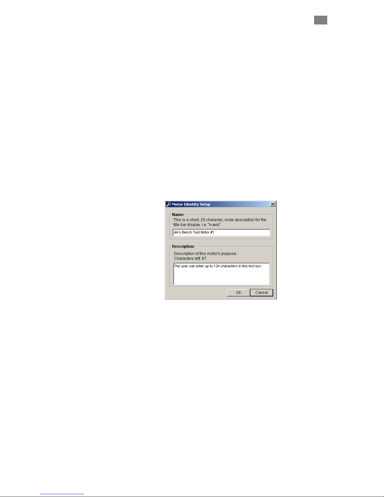
C
LEARPATH USER MANUAL REV.
C
LEARPATH
M
ENU
F
ILE MENU
Load Configuration (Ctrl+0). Use this command to load saved
ClearPath configuration files (extension .mtr) to your ClearPath.
Save Configuration (Ctrl+s). Use this command to save your
ClearPath configuration settings to a .mtr file.
Reset Config File to Factory Defaults. This command restores
ClearPath to its factory default configuration.
E
DIT MENU
Cut (Ctrl-x), Copy (Ctrl-c), and Paste (Ctrl-v) are the standard
Windows Edit commands.
Motor ID. Opens a window that lets you enter a name and brief
description for your ClearPath if desired.
1.97
36
Zero Position (Ctrl+0) Sets the Position Counter to zero. Note: In
certain modes, double-clicking the Position Counter directly in the UI will
also zero the counter.
Reset RMS Peak Note: This applies to the RMS Meter in the
Dashboard section of MSP. Click this menu item to reset RMS Max (this is
the maximum RMS value recorded since last reset).
M
Select ClearPath operating modes from this drop down menu. Note:
number of available modes varies by model.
S
Use this menu item to convert velocity and acceleration values from
encoder counts to RPM (revolutions per minute). Note: Motor position is
always displayed in encoder counts.
EKNIC, INC
T
.
ODE MENU
ETUP MENU
FAX
(585)784-7460
VOICE
(585)784-7454
Page 48

C
LEARPATH USER MANUAL REV.
A
DVANCED
1.97
M
ENU
37
The Adv
anced menu gives you access to several ClearPath global features
and settings. Each Advanced Menu item is listed below along wi th a
screenshot of it
s dialog window.
Torque Foldback
This feature automatically limits maximum available torque to the
specified value whenever the Move Done criteria are met. See Mov
criteria (next page) for details.
Tracking Error Limit
user-
e Done
EKNIC, INC
T
.
High-Level Feedback
Refer to section High-Level Feedback (HLFB).
FAX
(585)784-7460
VOICE
(585)784-7454
Page 49

C
BII
BII
ANNI
BII
BII
LEARPATH USER MANUAL REV.
Move Done Criteria
Move Done status is used to determine when the All Systems Go-Position
signal should be asserted at the HLFB output. The Move Done Criteria
consist of two parameters: the “In-Range Window” and the “Verify Ti
These parameters are explained in
below.
1.97
38
me”.
the screen capture, taken from MSP,
Move Done setup dialog
Move Direction
ENCODER
ANNI
Commanded Position (0)
Encoder Scale
(1 line = 1 count)
0
In-Range Window +/- 10 counts
Actual Position (count 5)
551015 10 15
How Move Done Works
Move Done status is achieved when both of the Move Done criteria are
met. In the above figure, Move Done occurs only when the motor is within
+/-10 encoder counts of the commanded position (the In-Range Window)
for a minimum of 10.1 milliseconds (the Verify Time).
Note: If the encoder swings out of the In-Range window during the Verify
Time, the Move Done timer automatically resets. The timer starts a new
countdown only when the motor is back within the In-Range window.
Because mechanical systems and settling performance requirements vary
by application, the user may need to experiment a bit to determine
appropriate values for the In-Range Window and Verify Time.
EKNIC, INC
T
.
FAX
(585)784-7460
VOICE
(585)784-7454
Page 50

C
LEARPATH USER MANUAL REV.
Input A and B Filtering
1.97
39
EKNIC, INC
T
.
FAX
(585)784-7460
VOICE
(585)784-7454
Page 51

C
LEARPATH USER MANUAL REV.
Disable Behavior
This setting determines how ClearPath will decelerate if it is disabled
while still in motion.
1.97
40
EKNIC, INC
T
.
FAX
(585)784-7460
VOICE
(585)784-7454
Page 52

C
LEARPATH USER MANUAL REV.
M
ODES OF
O
PERATIO
1.97
N:
MC F
AMILY
41
This section discusses ClearPath MC Family modes of operation, inclu
input/output function
programming, replace silicon plug over USB connector at back of motor.
T
ABLE OF CLEARPATH
Operation Mode
Velocity Control Modes
Spin On Power Up
Manual Velocity Control
Ramp Up/Down to Selected Velocity
Follow Digital Velocity Command
Bipolar PWM Command
Follow Digital Velocity Command
Unipolar PWM Command
Follow Digital Velocity Command
Frequency Command
Torque Control Modes
Follow Digital Torque Command
Bipolar PWM Command
MC F
MCVC
AMILY
Model
s, timing and software features and functions. After
O
MCPV
PERATIONAL MODES
Description
Just turn on power and smoothly ramp to your preset velocity. For when all you
need is reliable, constant velocity from a brushless motor, and a bare minimum
of wiring. It doesn't get any easier than this.
Fine control of velocity from zero to max velocity at the turn of a knob.
Remembers your last set velocity or resets to zero velocity when motor is
enabled.
By changing digital inputs (from your PLC, switches, etc.), ClearPath will
smoothly ramp to one of four preset velocities.
Connect a digital waveform (PWM or frequency) from your PLC or other device,
and ClearPath will run at a velocity proportional to the w veform. Or, use the
PWM output from an H-bridge driver of a brushed motor setup and ClearPath
becomes a high-performance drop-in replacement.
a
ding
Follow Digital Torque Command
Unipolar PWM Command
Follow Digital Torque Command
Frequency Command
Position Control Modes
Move to Sensor Position
Move to Absolute Position (2 Positions)
Move to Absolute Position (4 Positions)
Move Incremental Distance (2 Distances)
Move Incremental Distance (4 Distances)
Pulse Positioning Mode
Pulse Burst Positioning
ClearPath will apply a variable torque (or force or tension) in propo rtion to a
digital command (PWM or frequency) supplied to the inputs.
Use ClearPath digital inputs to spin the shaft CW or CCW. Wire your position
sensors or switches in series with the inputs to make an inexpensive, precision
two position actuator.
Command ClearPath to move to one of two preset locations. Perfect for
replacing air cylinders that move between two positions.
Command ClearPath to move to one of four preset locations. Perfect for
replacing air cylinders where more power and finesse is needed, and you want
to position at more than just two positions.
Trigger ClearPath to move a user-defined distance (one of two) from its current
position. You can also send multiple, quick trigger pulses to tell ClearPath to
travel a multiple of any of its user-defined distances in one smooth move.
Trigger ClearPath to move a user-defined distance (one of four) from its current
position. You can also send multiple, quick trigger pulses to tell ClearPath to
travel a multiple of any of its user-defined distances in one smooth move.
Use a timer/counter on your PLC (or a simple circuit) to send a burst of pulses
to ClearPath, and it will move a distance proportional to the number of pulses
sent, at your preselected velocity and acceleration. This mode gives you most
of the flexibility of a "step & direction" motion controller without the cost and
added complexity.
EKNIC, INC
T
.
FAX
(585)784-7460
VOICE
(585)784-7454
Page 53

C
LEARPATH USER MANUAL REV.
S
PIN ON POWER
M
ODE SUMMARY
U
P
1.97
42
This is ClearPath’s simplest mode of operation. Just turn on p
ClearPath smoothly ramps to your preset velocity. Use this m
applications that require reliable constant velocity and a bare minimum of
wiring.
H
OW IT WORKS
Apply main D e
C pow r and ClearPath immediately ramps up to your target
velocity (target velocity and
setup). Clear i
All inputs are d
Path sp
ignore
ns at th
, but t
Note: When i power s removed in this mode, ClearPath may stop abruptly
or coast a sho a otor winding rt dist nce depending on the application and m
configuration fu t your loaded ClearPath application for . Care lly tes
stopping behavior before deploying.
Velocity Control
Signal Function Input Type
Input A
Input B
Enable
Caution! Motor shaft may spin as soon as main DC power is applied.
Notes: All inputs are ignored in this mode. High-Level Feedback is available.
Motor will free-wheel when DC power is removed, unless external braking
force is applied. Motor may stop abruptly depending on load conditions.
Disabled
Disabled
Disabled NA
Spin On Power Up
NA
NA
NA
Main DC Power
ower and
ode for
acceleration are defined by the user during
e target velocity until DC power is removed.
he output (High-Level Feedback) is functional.
1
0
1
0
1
0
ON
OFF
v
Motor velocity vs. time
Example Timing
NA
NA
Motor free-wheeling
t
Spin-On-Power-Up Mode: Inputs and Timing Diagram
EKNIC, INC
T
.
FAX
(585)784-7460
VOICE
(585)784-7454
Page 54

C
LEARPATH USER MANUAL REV.
M
ODE CONTROLS
Enter target velocity.
1.97
Enter value (1-100) to limit
peak torque capability of
motor as a % of motor’s
maximum peak torque.
43
Enter maximum
desired motor
acceleration rate.
Check here to set
motor deceleration
rate to same value
as acceleration rate.
Enter maximum
desired motor
deceleration rate.
Set jerk limit. Higher values result in
smoother, more gradual transitions
between move segments of differing
acceleration; however, overall move
time is increased.
Displays output status.
HLFB modes supported:
> Servo On
> AllSystemsGo
> Speed Output
EKNIC, INC
T
.
FAX
(585)784-7460
VOICE
(585)784-7454
Page 55

C
LEARPATH USER MANUAL REV.
1.97
44
MANUAL VELOCITY CONTROL
M
ODE SUMMARY
This mode offers fine velocity control from zero to a user defined
maximum at the turn of a quadrature output device (such as a quadrature
output encoder). Turn in one direction to increase CW motor velocity;
turn in the other direction to increase CCW velocity. When enabled,
ClearPath can either resume running at its last set speed or start at zero
speed (and stay at zero speed until commanded to move).
H
OW IT WORKS
Assert the Enable Input to energize the motor. Then, control motor
velocity by sending quadrature signals to ClearPath Inputs A and B. Each
quadrature signal transition (or “tick”) received by ClearPath causes an
incremental increase or decrease in motor velocity, depending on which
direction the encoder is turned (i.e. whether phase A leads B or B leads A).
Velocity Control
Signal Function Input Type
Input A
Input B
Enable
Notes:
Velocity Control A
Velocity Control B
Enable
NA NATrigger
Manual Velocity Control
Quadrature
Quadrature
Logic: High=Enable Low=Disable
1
0
1
0
1
0
v
Motor velocity vs. time
Example Timing
Knob/encoder rotation reversed
t
Manual Velocity Control: Inputs and Timing Diagram
Notes:
• Disable time = 10 mS
Q
UADRATURE SIGNAL SOURCE
To use this mode you’ll need a device that can generate quadrature signals
in the 5-24VDC range. Many users choose an optical or mechanical
incremental encoder for this task, but a microcontroller or digital signal
generator will work as well. Note: mechanical quadrature encoders are
generally the least expensive option.
Quadrature output from a rotary encoder, aka “the knob”
EKNIC, INC
T
.
FAX
(585)784-7460
VOICE
(585)784-7454
Page 56

C
LEARPATH USER MANUAL REV.
M
ODE CONTROLS
1.97
45
Enter maximum (full-scale)
motor velocity for CW and
CCW shaft rotation.
Enter maximum
desired motor
acceleration rate.
Check here to set
motor deceleration
rate to same value
as acceleration rate.
Hardware Input Status LEDs
Light = Input asserted (on)
Dark = Input de-asserted (off )
Enter desired incremental
increase / decrease in motor
velocity per quadrature tick.
Enter maximum
desired motor
deceleration rate.
Set jerk limit. Higher values
result in smoother, more
gradual transitions between
move segments of differing
acceleration; however, overall
move time is increased.
“Has Detents” Checkbox
See text for description.
Displays commanded speed
(when using hardware inputs).
Reverse sense of motor
direction with respect to
quadrature phasing, or leave
As-Wired. Eliminates need to
rewire inputs if motor rotates
the “wrong” way initially.
Enter value (1-100) to limit
peak torque capability of
motor as a % of motor’s
maximum peak torque.
Set motor to initialize to
either Zero Velocity or
Last Commanded
velocity each time
ClearPath is enabled.
Check to turn on Soft
Controls. Override cannot
be activated when ClearPath
is hardware enabled.
D
ESCRIPTION S
Check to soft enable ClearPath
(This only works when Soft
Controls are active) Caution:
motor may spin when enabled.
OF ENCODER
M
AX
CW V
ELOCITY
/K
NOB SETTING
This setting defines the maximum motor shaft velocity that can be
reached when the quadrature knob is
CW shaft rotation.
M
AX
CCW V
ELOCITY
This setting defines the maximum shaft velocity that can be reached when
the quadrature knob is turned in the direction that elicits CCW shaft
rotation.
Click arrows to increase or
decrease motor velocity by
increment defined in “Velocity
Resolution” field above. Each
“arrow click” is equivalent to a
hardware quadrature “tick ”.
turned in the direction that elicits
Displays output status
HLFB modes supported:
> Servo On
> AllSYstemsGo
> Speed Output
EKNIC, INC
T
.
FAX
(585)784-7460
VOICE
(585)784-7454
Page 57

C
LEARPATH USER MANUAL REV.
V
This setting defines exactly how much (i.e., by what increment) motor
velocity will increase or decrease per quadrature “tick”.
K
These setting allow the user to reverse the motor’s sense of direction with
respect to the quadrature device phasing.
“H
When unchecked, ClearPath treats each quadrature transition it sees as
a single “tick”. (Remember, each tick causes an incremental change in
motor speed.)
When checked, ClearPath treats every 4
at its inputs as one “tick”. (Remember, each “tick” causes an incremental
change in motor speed.) Check this box when using an encoder that has
one detent point per full quadrature cycle or if you want to divide your
quadrature resolution by four.
CITY RESOLUTION
ELO
NOB DIRECTION
AS DETENTS” CHECKBOX
1.97
46
th
quadrature transition it sees
EKNIC, INC
T
.
FAX
(585)784-7460
VOICE
(585)784-7454
Page 58

C
LEARPATH USER MANUAL REV.
R
AMP
UP/D
M
ODE SUMMA
H
OW IT WORK
OWN TO SELECTED
RY
Changing the digital inputs on ClearPath (using your PLC, switches, etc.)
causes ClearPath to smoothly ramp betwee
velocities.
S
1.97
V
ELOCITY
47
n any of four user defined
Assert the Enable Input to get started. Once enabled, ClearPath reads th
state of Inputs A and B and
immediately accelerates to the target velocity
indicated. For example, if Input A is high and Input B is low
ClearPath will ramp to “Velocity 2”. Change to aq different velocity by
changing Inputs A and B.
Velocity Control
Signal Function Velocity Settings (logic levels) Example Timing
Input A
Input B
Enable
Tip: Setting one of the programmable velocities to zero (Velocity 3 in the example
at right) provides a convenient way to stop the motor via the ClearPath inputs.
Ramp Up/Down to Selected Velocity Mode: Inputs and Timing Diagram
Velocity Select A
Velocity Select B
Enable
NA NATrigger
Ramp Up/Down to Selected Velocity (4 Velocity Programmable)
Velocity 1 Velocity 2 Velocity 3 Velocity 4
LOW
LOW
Logic: High=Enable Low=Disable
HIGH
LOW
LOW
HIGH
HIGH
HIGH
1
0
1
0
1
0
1
0
v
Velocity 1
0
Motor velocity vs. time
Velocity 2
Notes:
• As soon as a new velocity command is received by ClearPath—as
happens when Inputs A and/or B are changed—ClearPath
immediately ramps to the new target velocity without delay.
• For a convenient way to command ClearPath to stop, set one of
the velocity settings to zero. We did this with “Velocity 3” in the
table above.
• Disable time = 10 mS
Velocity 3
Velocity 4
e
t
EKNIC, INC
T
.
FAX
(585)784-7460
VOICE
(585)784-7454
Page 59

C
LEARPATH USER MANUAL REV.
M
ODE CONTROLS
Enter target velocity for
each input state here.
1.97
48
Enter value (1-100) to limit
peak torque capability of
motor as a % of motor’s
maximum peak torque.
Enter maximum
desired motor
acceleration rate.
Check to turn on Soft
Controls. Override cannot
be activated when ClearPath
is hardware enabled.
Check here to set
motor deceleration
rate to same value
as acceleration rate.
Enter maximum
desired motor
deceleration rate..
Hardware Input Status LEDs
Light = Input asserted (on)
Dark = Input de-asserted (off )
Soft Inputs and LEDs emulate
hardware inputs. For use only
when Soft Controls are active.
Caution: motor may spin when
enabled.
Set jerk limit. Higher values result in
smoother, more gradual transitions
between move segments of differing
acceleration; however, overall move
time is increased.
Displays commanded velocity
(when using hard inputs).
Displays commanded velocity
(when using soft inputs).
Displays output status.
HLFB modes supported:
>Servo On
>AllSystemsGo
EKNIC, INC
T
.
FAX
(585)784-7460
VOICE
(585)784-7454
Page 60

C
LEARPATH USER MANUAL REV.
F
OLLOW
D
IGITAL VELOCITY
M
ODE SUMMARY
H
OW IT WORKS
Connect a digital PWM waveform from your PLC or other device, and
ClearPath will run at a velocity proportional to the duty cycle of that
waveform. Or, use the PWM output from an H-bridge driver of a brushed
motor setup and ClearPath becomes a high-performance drop-in
replacement.
Assert the Enable Input to energize the motor. Control motor speed and
direction by modulating the duty cycle of the PWM signal. Assert th e
Inhibit signal (Input A) to immediately ramp to zero velocity. See figure
below and read text for timing and PWM requirements.
1.97
C
OMMAND
(BI-P
OLAR
PWM I
NPUT
49
)
Velocity Control
Signal Function Input Type
Input A
Input B
Enable
Notes: Asserting Inhibit Input causes immediate ramp to zero speed. See text for
information on deadband set up and application.
Follow Digital Velocity Command (Bi-Polar PWM Control): Inputs and Timing Diagram
Inhibit (optional)
Speed/Direction
Enable
NA NATrigger
Follow Digital Velocity Command (Bi-Polar PWM Command)
Logic: High=Inhibit on Low=Inhibit off
Pulse: Variable PWM
Duty cycle of applied PWM signal (%)
Logic: High=Enable Low=Disable
1
0
1
0
1
0
1
0
v
Motor velocity vs. time
Inside deadband
Example Timing
90%50%
Inhibit on
10%
Notes:
• PWM input frequency range: 20 Hz up to 30 kHz.
• If the PWM signal is off for 50mS or more the PWM input is
considered off. This is interpreted by ClearPath as a zerovelocity command.
• Disable time = 10 mS
• Command ClearPath to immediately ramp to zero velocity by
asserting the Inhibit Input (Input A). De-assert Input A to
resume normal operation.
or
• Set a PWM deadband to help reliably command zero velocity.
Read text for details on deadband setup.
• PWM Input, especially at higher frequencies, tends to have
more inherent inaccuracy. If a very high level of velocity
accuracy is important for your application, consider using
Frequency Input mode.
t
EKNIC, INC
T
.
FAX
(585)784-7460
VOICE
(585)784-7454
Page 61

C
LEARPATH USER MANUAL REV.
M
ODE CONTROLS
1.97
50
Enter maximum
motor speed (i.e.
full scale speed).
Enter maximum
desired motor
acceleration rate.
Enter deadband setting (optional). See text
for description of deadband operation.
Check here to set
motor deceleration
rate to same value
as acceleration rate.
Hardware Input Status LEDs
Light = Input asserted (on)
Dark = Input de-asserted (off )
Enter maximum
desired motor
deceleration rate..
Set jerk limit. Higher values result in
smoother, more gradual transitions
between move segments of differing
acceleration; however, overall move
time is increased.
PWM Meter - Displays
duty cycle of PWM source
connected to Input B.
Enter value (1-100) to limit
peak torque capability of
motor as a % of motor’s
maximum peak torque.
Displays commanded
velocity (when using
hard controls).
Check to turn on Soft
Controls. Override cannot
be activated when ClearPath
is hardware enabled.
Soft Inputs and LEDs
Emulate hardware inputs. For
use only when Soft Controls
are active. Caution: motor
may spin when enabled.
PWM Soft Slider
Emulates PWM
input (for use with
Soft Controls).
Displays commanded
velocity (when using
Soft Controls).
Displays output status
HLFB modes supported:
>Servo On
>AllSystemsGo
>Speed Output
EKNIC, INC
T
.
FAX
(585)784-7460
VOICE
(585)784-7454
Page 62

C
LEARPATH USER MANUAL REV.
onship of PWM duty cycle to motor velocity Relati
• Shaft velocity increases in the CW direction as PWM duty cycle
decreases from 50% to 0%
• Shaft velocity increases in the CCW direction as PWM duty cycle
increases from 50% to 100%
• As PWM duty cycle approaches 50%—from either direction—motor
velocity approaches 0.
• In practice, O% and 100% (static low and static high conditions) are
not valid PWM states. ClearPath treats these cases as zero-velocity
commands.
• PWM minimum on time and minimum off time = 300nS.
Max. Velocity
(CCW Rotation)
1.97
51
Velocity = 0
Max. Velocity
(CW Rotation)
10 20 30 40 50 60 70 80 90 1000
Duty Cycle
Graph of PWM duty cycle vs. motor velocity
Zero
Velocity
EKNIC, INC
T
.
FAX
(585)784-7460
VOICE
(585)784-7454
Page 63

C
LEARPATH USER MANUAL REV.
S
ETTING
A
PWM
DEADBAND
The deadband expands the range about the 50% PWM mark that is
i t
n erpreted as the “zero-velocity s
a reliable way to ensure that motor velocity ramps to zero when the PW
duty cycle is set at (or “close enou
Max. Velocity
(CCW Rotation)
Velocity = 0
Max. Velocity
(CW Rotation)
1.97
(O
PTIONAL
10 20 30 40 50 60 70 80 90 1000
52
)
etting” by ClearPath. This gives the user
M
gh” to) 50%.
Deadband
(+/- 5%)
Duty Cycle
+/- 5% PWM dead band setting
Why use a deadband?
In bi-polar mode, stopping the motor (i.e. commanding “zero velocity”) is
achieved, in theory, by applying a 50% duty cycle PWM signal to Input B.
However, it can be technically challenging to set a perfect 50% duty cycle.
In fact, some very low speed motion may still be observed at the motor
shaft even when duty cycle is apparently set to 50%. A deadband helps to
ensure that actual motor velocity is zero (with no drift) when you expect it
to be.
Example: If the user sets a +/- 5% dead band, any PWM signal with a
duty cycle between 45% and 55% will be interpreted as a zero-velocity
command by ClearPath. See figure above.
Note: As size of deadband setting increases, the slope of velocity vs. duty
cycle increases as illustrated below.
EKNIC, INC
T
.
FAX
(585)784-7460
VOICE
(585)784-7454
Page 64

C
LEARPATH USER MANUAL REV.
F
OLLOW
D
IGITAL VELOCITY
M
ODE SUMMA
H
OW IT WORKS
RY
Connect a digital PWM waveform from your PLC or other device, and
ClearPath will run at a speed proportional to the duty cycle of the PWM
waveform.
Assert the Enable Input to energize the motor. Once enabled, motor
velocity is controlled by sending a PWM signal to Input B. 0% PWM duty
cycle commands zero velocity, and 100% (minus a little) duty cycle
commands full-scale velocity. Changes in velocity occur at the userdefined acceleration rate.
Direction of travel (CW/CCW) is controlled by the state of Input A. See
Inputs and Timing table below.
1.97
C
OMMAND
(U
NIPOLAR
PWM I
NPUT
53
)
Velocity Control
Signal Function Input Type
Input A
Input B
Enable
Notes:
Follow Digital Velocity
Direction
Velocity
Enable
NA NATrigger
Follow Digital Velocity Command (Unipolar PWM Command)
Logic: High=CW Low=CCW
Pulse: Variable PWM
Duty cycle of applied PWM signal (%)
Logic: High=Enable Low=Disable
Command (Unipolar PWM Control): Inputs and Timing Diagram
1
0
1
0
1
0
1
0
v
Motor velocity vs. time
Example Timing
90%10% OFF
Notes:
• PWM input frequency range: 20 Hz up to 30 kHz.
• If the PWM signal is off for 50Ms
or more the PWM input is
considered off. This is interpreted by ClearPath as a zerovelocity command.
• Disable time = 10 mS
• PWM Input, especially at higher frequencies, tends to have
more inherent inaccuracy. If a very high level of velocity
accuracy is important for your application, consider using
Frequency Input mode.
t
EKNIC, INC
T
.
FAX
(585)784-7460
VOICE
(585)784-7454
Page 65

C
LEARPATH USER MANUAL REV.
M
ODE CONTROLS
Enter maximum
motor speed (i.e.
full-scale speed).
1.97
54
Enter value (1-100) to limit
peak torque capability of
motor as a % of motor’s
maximum peak torque.
Enter maximum
desired motor
acceleration rate.
Check to turn on Soft
Controls. Override cannot
be activated when ClearPath
is hardware enabled.
Check here to set
motor deceleration
rate to same value
as acceleration rate.
Enter maximum
desired motor
deceleration rate..
Hardware Input Status LEDs
Light = Input asserted (on)
Dark = Input de-asserted (off )
Soft Inputs and LEDs
Emulate hardware inputs. For
use only when Soft Controls
are active. Caution: motor
may spin when enabled.
Motor velocity vs. PWM duty cycle:
• Motor velocity is proportional to PWM duty cycle (
• In practice, 0% and 100% duty cycle signals (static low an
Set jerk limit. Higher values result in
smoother, more gradual transitions
between move segments of differing
acceleration; however, overall move
time is increased.
PWM Meter - Displays
duty cycle of PWM source
connected to Input B.
PWM Soft Slider
Emulates PWM
input (for use with
Soft Controls).
Displays commanded
velocity (when using
hard controls).
Displays commanded
velocity (when using
Soft Controls).
Displays output status
HLFB modes supported:
>Servo On
>AllSystemsGo
>Speed Output
increases as duty cycle increases). See figure below.
static high respectiv
ClearPath as “PWM tu
ely) are invalid PWM states, interpreted by
rned off”. This is the equivalent of a zero-
velocity command.
velocity
d
EKNIC, INC
T
.
Max. Velocity
(user set)
Velocity
0
0
PWM Duty Cycle (%)
FAX
(585)784-7460
50
100
VOICE
(585)784-7454
Page 66

C
LEARPATH USER MANUAL REV.
For CW shaft rotation, set Input A high. For CCW shaft rotation,
•
• PWM minimum on time and minimum off time = 300nS
1.97
set Input A low.
55
EKNIC, INC
T
.
FAX
(585)784-7460
VOICE
(585)784-7454
Page 67

C
LEARPATH USER MANUAL REV.
F
OLLOW
D
IGITAL VELOCITY
M
ODE SUMMARY
H
OW IT
W
Connect a digital variable frequency waveform from your PLC or other
device, and ClearPath will run at a velocity proportional to the frequency
of the waveform.
ORKS
Assert the Enable Input to energize the motor. Then, control velocity by
applying a variable frequency pulse train to Input B. Pulse frequency is
proportional to commanded velocity. Direction of travel (CW/CCW) is
controlled by the state of Input A. See Inputs and Timing table below.
1.97
C
OMMAND
(F
REQUENCY INPUT
56
)
Velocity Control
Signal Function Input Type
Input A
Input B
Enable
Notes:
Follow Digital Velocity Command (Frequency Input Control): Inputs and Timing Diagram
Direction
Velocity
Enable
NA NATrigger
Follow Digital Velocity Command (Frequency Input Control)
Logic: High=CW Low=CCW
Pulse: Variable Frequency
Logic: High=Enable Low=Disable
1
0
1
0
1
0
1
0
v
Motor velocity vs. time
Example Timing
Notes:
• Input frequency range: 20 Hz to 500 kHz.
• If the frequency signal is off for 50mS or more the input is
considered off. This is interpreted by ClearPath as a zerovelocity command.
• Disable time = 10 mS
t
EKNIC, INC
T
.
FAX
(585)784-7460
VOICE
(585)784-7454
Page 68

C
LEARPATH USER MANUAL REV.
M
ODE CONTROLS
Enter maximum
motor speed (i.e.
full scale speed).
Set Min/Max Frequency. During operation, motor speed is
controlled by Input B signal frequency. With the settings below, a 30
kHz signal at Input B will cause the motor to spin at the Max Speed
setting (20 kcounts/sec); a 1 kHz signal will command zero speed.
1.97
57
Enter value (1-100) to limit
peak torque capability of
motor as a % of motor’s
maximum peak torque.
Enter maximum
desired motor
acceleration rate.
Check to turn on Soft
Controls. Override cannot
be activated when ClearPath
is hardware enabled.
Check here to set
motor deceleration
rate to same value
as acceleration rate.
Enter maximum
desired motor
deceleration rate..
Hardware Input Status LEDs
Light = Input asserted (on)
Dark = Input de-asserted (off )
Soft Inputs and LEDs
Emulate hardware inputs. For
use only when Soft Controls
are active. Caution: motor
may spin when enabled.
Set jerk limit. Higher values result in
smoother, more gradual transitions
between move segments of differing
acceleration; however, overall move
time is increased.
Frequency Meter
Displays frequency of
input signal source
connected to Input B.
Frequency Soft Slider
Emulates frequency
input source (for use
with Soft Controls).
Displays commanded
velocity (when using
hard controls).
Displays commanded
velocity (when using
Soft Controls).
Displays output status
HLFB modes supported:
>Servo On
>AllSystemsGo
>Speed Output
EKNIC, INC
T
.
FAX
(585)784-7460
VOICE
(585)784-7454
Page 69

C
LEARPATH USER MANUAL REV.
F
OLLOW
D
IGITAL TORQUE
M
ODE SUMMARY
H
OW IT WORKS
Connect a digital PWM waveform from your PLC or other device, and
ClearPath will produce torque proportional to the duty cycle of the PWM
waveform.
Assert the Enable Input to energize the motor. Control motor torque by
applying a PWM signal to Input B. Motor torque changes in proportion to
the duty cycle of the applied PWM signal. Assert the Inhibit signal (Input
A) to immediately turn off torque. See figure below and read text for
timing and PWM requirements.
1.97
C
OMMAND
(BI-
POLAR
PWM I
NPUT
58
)
Torque Control
Signal Function Input Type
Input A
Input B
Enable
Notes: Asserting Inhibit Input causes immediate jump to zero torque. See text for
information on deadband set up and application.
Follow Digital Torque Command (Bi-polar PWM Control): Inputs and Timing Diagram
Inhibit (optional)
Torque/Direction
Enable
NA NATrigger
Follow Digital Torque Command (Bi-Polar PWM Command)
Logic: High=Inhibit on Low=Inhibit off
Pulse: Variable PWM
Duty cycle of applied PWM signal (%)
Logic: High=Enable Low=Disable
1
0
1
0
1
0
1
0
tq
Motor torque vs. time
Inside deadband
Example Timing
90%50%
Inhibit on
20%
Notes:
• PWM input frequency range: 20 Hz to 30 kHz.
• If the PWM signal is off for 50mS (or more) the PWM input is
considered off. This is interpreted by ClearPath as a zero-torque
command.
• Disable time = 10 mS
• To command ClearPath to zero torque, assert the Inhibit Input
(Input A). De-assert Input A to resume normal operation.
or
• Set a PWM deadband to help reliably command zero torque.
Refer to text on following pages for details on deadband setup.
t
EKNIC, INC
T
.
FAX
(585)784-7460
VOICE
(585)784-7454
Page 70

C
LEARPATH USER MANUAL REV.
M
ODE CONTROLS
1.97
59
Enter maximum
motor torque (i.e.
full scale torque).
Check to turn on Soft
Controls. Override cannot
be activated when ClearPath
is hardware enabled.
Enter deadband setting
(optional). See text for
description of deadband.
Enter maximum speed.
ClearPath will shut down if
this speed limit is exceeded.
Hardware Input Status LEDs
Light = Input asserted (on)
Dark = Input de-asserted (off )
Soft Inputs and LEDs
Emulate hardware inputs. For
use only when Soft Controls
are active. Caution: motor
may spin when enabled.
PWM Meter - Displays
duty cycle of PWM source
connected to Input B.
PWM Soft Slider
Emulates PWM
input (for use with
Soft Controls).
Enter value in mS. Determines
how long ClearPath can spin at
max speed before shutting down.
Displays commanded
torque (when using
hard controls).
Displays commanded
torque (when using
Soft Controls).
Displays output status
HLFB modes supported:
>Servo On
>AllSystemsGo
>Speed Output
EKNIC, INC
T
.
FAX
(585)784-7460
VOICE
(585)784-7454
Page 71

C
LEARPATH USER MANUAL REV.
ionship of PWM duty cycle to motor torque Relat
• Shaft torque increases in the CW direction as PWM duty cycle
decreases from 50% to 0%.
• Shaft torque increases in the CCW direction as PWM duty cycle
increases from 50% to 100%.
• As PWM duty cycle approaches 50% from either direction, motor
torque approaches 0.
• O% and 100% duty cycle (static low and static high conditions) are not
valid PWM states. ClearPath interprets these values as zero-torque
commands.
• PWM minimum on time and minimum off time = 300nS.
Max. Torque
(CCW Rotation)
1.97
60
Torque = 0
Max. Torque
(CW Rotation)
10 20 30 40 50 60 70 80 90 1000
PWM duty cycle vs. motor torque
Duty Cycle
Zero
Torque
EKNIC, INC
T
.
FAX
(585)784-7460
VOICE
(585)784-7454
Page 72

C
LEARPATH USER MANUAL REV.
S
ETTING A
PW
M D
EADBAND
The deadband expands the range about the 50% PWM mark that is
n erpreted as the “zero torque settii t
reliable way to ensure that motor torque is completely turned off whe
PWM duty cycle is set at (or “close
Max. Torque
(CCW Rotation)
Torque = 0
Max. Torque
(CW Rotation)
1.97
(O
PTIONAL
10 20 30 40 50 60 70 80 90 1000
61
)
ng” by ClearPath. This gives the user a
n the
enough” to) 50%.
Deadband
(+/- 5%)
Duty Cycle
+/- 5% PWM deadband setting
Why use a deadband?
In bi-polar mode, turning off torque is achieved, in theory, by applying a
50% duty cycle PWM signal to Input B. However, it can be difficult to set a
perfect 50% duty cycle. In fact, a very small amount of torque may still be
produced by the motor, even when duty cycle is apparently set to 50%. A
deadband helps guarantee torque is fully off when you expect it to be.
Example: If the user sets a +/-5% deadband, any PWM signal with a
duty cycle between 45% and 55% (i.e., in the deadband) is interpreted as a
zero-torque command by ClearPath.
Note: As deadband setting increases, the slope of torque vs. duty cycle
increases as illustrated below.
EKNIC, INC
T
.
FAX
(585)784-7460
VOICE
(585)784-7454
Page 73

C
LEARPATH USER MANUAL REV.
F
OLLOW
D
IGITAL TORQUE
M
ODE SUMMA
H
OW IT WORKS
RY
Connect a digital PWM waveform from your PLC or other device, and
ClearPath will run at a speed proportional to the duty cycle of the PWM
waveform.
Assert the Enable Input to energize the motor. Motor torque is controlled
be applying a variable PWM signal to Input B. 0% PWM duty cycle
commands zero torque, and 100% duty cycle commands full-scale torque.
Changes in speed occur at the user-defined acceleration rate. Direction of
shaft rotation is controlled by the state of Input A. See Inputs and Timing
table below.
1.97
C
OMMAND
(U
NIPOLAR
PWM I
NPUT
62
)
Torque Control
Signal Function Input Type
Input A
Input B
Enable
Notes:
Variable Torque Mode
Direction
Torque
Enable
NA NATrigger
Variable Torque With Unipolar PWM Input Control
Logic: High=CW Low=CCW
Pulse: Variable PWM
Duty cycle of applied PWM signal (%)
Logic: High=Enable Low=Disable
(Unipolar PWM Control): Inputs and Timing Diagram
1
0
1
0
1
0
1
0
tq
Motor torque vs. time
Example Timing
90%10% OFF
Notes:
• PWM input frequency range: 20 Hz to 30 kHz.
• If the PWM signal is off for
50mS (or more) the PWM input is
considered off. This is interpreted by ClearPath as a zero-torq
command.
• Disable time = 10 mS
t
ue
EKNIC, INC
T
.
FAX
(585)784-7460
VOICE
(585)784-7454
Page 74

C
LEARPATH USER MANUAL REV.
M
ODE CONTROLS
1.97
63
Enter maximum
motor torque (i.e. full
scale torque).
Check to turn on Soft
Controls. Override cannot
be activated when ClearPath
is hardware enabled.
Enter maximum speed.
ClearPath will shut down if
this speed limit is exceeded.
Hardware Input Status LEDs
Light = Input asserted (on)
Dark = Input de-asserted (off )
Soft Inputs and LEDs
Emulate hardware inputs. For
use only when Soft Controls
are active. Caution: motor
may spin when enabled.
Enter value in mS. Determines
how long ClearPath can spin at
max speed before shutting down.
PWM Meter - Displays
duty cycle of PWM source
connected to Input B.
PWM Soft Slider
Emulates PWM
input (for use with
Soft Controls).
Displays commanded
torque (when using
hard controls).
Displays commanded
torque (when using
Soft Controls).
Displays output status
HLFB modes supported:
>Servo On
>AllSystemsGo
>Speed Output
Motor torque vs. PWM duty cycle:
• Motor torque is proportional to PWM duty cycl
increases as duty cycle increases). See figure be
e (i.e. torque
low.
• 0% and 100% duty cycle signals (static low and static high
respectively) are invalid PWM states, interpreted by ClearPath
as “PWM turned off”. This is the equivalent of a
zero-torque
command.
Max. Torque
(user set)
Torque
0
0
PWM Duty Cycle (%)
PWM duty cycle vs. torque
50
100
• For CW torque, set Input A high. For CCW torque, set Input A
low.
• PWM minimum on time and minimum off time = 300nS
EKNIC, INC
T
.
FAX
(585)784-7460
VOICE
(585)784-7454
Page 75

C
LEARPATH USER MANUAL REV.
F
OLLOW
D
IGITAL TORQUE
M
ODE SUMMARY
H
OW IT
W
Connect a digital variable frequency waveform from your PLC or other
device, and ClearPath will produce torque that is proportional to the
frequency of the waveform.
ORKS
Assert the Enable Input to energize the motor. Control torque by applying
a variable frequency pulse train to Input B. Pulse frequency is
proportional to commanded torque. Direction in which torque is applied
(CW/CCW) is controlled by the state of Input A. See Inputs and Timing
table below.
1.97
C
OMMAND
(F
REQUENCY INPUT
64
)
Torque Control
Signal Function Input Type
Input A
Input B
Enable
Notes:
Variable Torque Mode g Diagram
Direction
Torque
Enable
NA NATrigger
Variable Torque With Frequency Input Control
Logic: High=CW Low=CCW
Pulse: Variable Frequency
Logic: High=Enable Low=Disable
(Frequency Control): Inputs and Timin
1
0
1
0
1
0
1
0
tq
Motor torque vs. time
Example Timing
Notes:
• Input frequency range: 20 Hz to 500 kHz.
• If the frequency signal is off for 50mS or more the input is
considered off. This is interpreted by ClearPath as a zero-torq
command.
• Disable time = 10 mS
t
ue
EKNIC, INC
T
.
FAX
(585)784-7460
VOICE
(585)784-7454
Page 76

C
LEARPATH USER MANUAL REV.
M
ODE CONTROLS
Enter maximum
motor torque (i.e. full
scale torque).
Set Min/Max Frequency. During operation,
motor torque is controlled by Input B signal
frequency. With the settings below, a 30 kHz
input signal will command the motor to the
Max Torque setting (25% of peak ); a 1 kHz
signal will command zero torque.
1.97
Enter maximum speed.
ClearPath will shut down if
this speed limit is exceeded.
Enter value in mS. Determines
how long ClearPath can spin at
max speed before shutting down.
65
Check to turn on Soft
Controls. Override cannot
be activated when ClearPath
is hardware enabled.
Hardware Input Status LEDs
Light = Input asserted (on)
Dark = Input de-asserted (off )
Soft Inputs and LEDs
Emulate hardware inputs. For
use only when Soft Controls
are active. Caution: motor
may spin when enabled.
Frequency Meter
Displays frequency of signal
source connected to Input B.
Frequency Soft Slider
Emulates frequency
input (for use with Soft
Controls) .
Displays commanded
torque (when using
hard controls).
Displays commanded
torque (when using
Soft Controls).
Displays output status
HLFB modes supported:
>Servo On
>AllSystemsGo
>Speed Output
EKNIC, INC
T
.
FAX
(585)784-7460
VOICE
(585)784-7454
Page 77

C
LEARPATH USER MANUAL REV.
M
OVE TO
A
BSOLUTE POSITION
M
ODE SUMMARY
H
OW IT
W
Trigger ClearPath to move to one of two preset locations. This mode was
designed for replacing hydraulic or pneumatic cylinders that move
between two positions.
ORKS.
Assert the Enable Input to energize the motor. Once enabled, ClearPath
automatically executes a homing move to a [user-supplied] switch or
sensor wired to Input B. Once a home position is established, ClearPath
automatically moves to one of the two user-defined positions (based on
the state of Input A). After that, just toggle Input A to move between the
two target positions.
1.97
(2-P
OSITION
)
Absolute Position
66
An absolute position is referenced to an established “home” position. Your
target positions, in this context, are defined in terms of distance from the
home position. For example, Position 1 could be defined as 5200 encoder
counts from home, while Position 2 might be defined as 2000 encoder
counts from home.
Position Control
Signal Function Input Type
Input A
Input B
Enable
Notes: ClearPath must home to a switch upon enable to establish the Home
(zero) position to which the other target positions are referenced.
Absolute Position Mode (2): Inputs and Timing Diagram
Position Select
Home Switch
Enable
NA NATrigger
Absolute Position (2-Position Programmable)
Logic: High=Pos. 2 Low=Pos. 1
Logic: High=Home Low= Not Home
Logic: High=Enable Low=Disable
p+
p-
1
0
1
0
1
0
1
0
Notes:
• If the state of Input A is changed during a move, ClearPath will
immediately ramp to a stop and move to the newly indicated
position.
• Input B switch polarity can be inverted via a checkbox in the
Homing Setup dialog. When home switch polarity is inverted,
ClearPath interprets Input B-low as “in the home switch”, and
Input B-high as “not in the home switch”.
• Disable time = 10 mS
Example Timing
Pos 1
Home
Motor position vs. time
Pos 2
Pos 1
Pos 2
t
EKNIC, INC
T
.
FAX
(585)784-7460
VOICE
(585)784-7454
Page 78

C
LEARPATH USER MANUAL REV.
M
ODE CONTROLS
1.97
67
Set Position 1
Enter distance
from home in
encoder counts.
Enter max motor
speed allowed.
Set Position 2
Enter distance
from home in
encoder counts.
Enter motor
acceleration rate.
Hardware Input Status LEDs
Light = Input asserted (on)
Dark = Input de-asserted (off )
Set jerk limit. Higher values result in
smoother, more gradual transitions
between move segments of differing
acceleration; however, overall move
time is increased.
Enter value (1-100) to limit
peak torque capability of
motor as a % of motor’s
maximum peak torque.
Click to open Homing
Setup window. Refer
to text for instructions
on homing setup.
Check to turn on Soft
Controls. Override
cannot be activated
when ClearPath is
hardware enabled.
H
OMING
S
Soft Inputs and LEDs
Emulate hardware inputs. For
use only when Soft Controls
are active. Caution: motor
may spin when enabled.
ETUP
(H
OME
-TO-S
WITCH
)
Displays output status
HLFB modes supported:
>Servo On
>AllSystemsGo
>Speed Output
Homing is required in this mode. Follow the instructions below to set up
switch homing.
1. Securely fasten a limit switch or sensor to one end of the
motion axis and wire it to
Input B.
2. Click the Setup button to open the homing dialog.
. Enter homing parameters. See figure next page for description
3
of homing parameters.
EKNIC, INC
T
.
FAX
(585)784-7460
VOICE
(585)784-7454
Page 79

C
LEARPATH USER MANUAL REV.
1.97
68
Homing setup dialog
4. Test and modify your homing setup for proper performance.
How Switch Homing Works:
• During homing, the axis is automatically driven toward the
homing switch at the user-specified direction and speed.
• Once the switch is actuated, the motor ramps to a stop and the
encoder position counter is zeroed. This position is now
considered the home reference position.
EKNIC, INC
T
.
FAX
(585)784-7460
VOICE
(585)784-7454
Page 80

C
LEARPATH USER MANUAL REV.
M
OVE TO
M
H
A
BSOLUTE POSITION
ODE SUMMARY
OW IT
W
ORKS
Command ClearPath to move to one of four preset locations. Perfect for
replacing air cylinders in scenarios where more power and/or finesse are
needed (and you want to position at more than just two locations).
An absolute position is referenced to an established “home” position. Your
target positions, in this context, are defined in terms of distance from the
home position. For example, Position 1 might be defined as 2000 encoder
counts from home, while Position 2 might be defined as 5200 encoder
counts from home.
Assert the Enable Input to energize the motor. Once enabled ClearPath
automatically homes to a hard stop to establish an absolute home
reference position. Note: Homing is required in this mode.
1.97
(4-P
OSITION
)
Absolute Position
69
After homing, ClearPath ca
defined positions by cha
n be commanded to move to any of four user-
nging the state of Input A and B. Changing these
inputs has the dual effect of selecting target position, and triggering the
ove. See table below for timing and input details. All moves execute at
m
ned speed and acceleration.
Position Control
the user-defi
Absolute Positioning (4-Position Programmable)
Signal Function Position Settings Example Timing
Pos. 1 Pos. 2 Pos. 3 Pos. 4
Input A
Input B
Enable
Notes: ClearPath must home to a “hard stop” (either upon first enable or upon
every enable) to establish a home reference position. All user-defined target
positions are referenced to the home position.
Absolute Position Mode (4-position): Inputs and Timing Diagram
Position Select A
Position Select B
Enable
NA NATrigger
LOW
LOW
Logic: High=Enable Low=Disable
HIGH
LOW
LOW
HIGH
HIGH
HIGH
p+
p-
1
0
1
0
1
0
1
0
Pos 2
Pos 1
Home
Motor position vs. time
Notes:
• Changing the state of Input A and/or B while ClearPath is in
motion cancels the move in progress. ClearPath immediately
ramps to a stop and initiates a new move to the newly indicated
target position.
• Disable time = 10 mS
Pos 3
Pos 4
t
EKNIC, INC
T
.
FAX
(585)784-7460
VOICE
(585)784-7454
Page 81

C
LEARPATH USER MANUAL REV.
M
ODE CONTROLS
1.97
70
Enter maximum
motor speed allowed.
Set Target Positions
Enter move distance (from
home) for each input state.
Enter motor
acceleration rate.
Hardware Input Status LEDs
Light = Input asserted (on)
Dark = Input de-asserted (off )
Set jerk limit. Higher values result in
smoother, more gradual transitions
between move segments of differing
acceleration; however, overall move
time is increased.
Enter value (1-100) to limit
peak torque capability of
motor as a % of motor’s
maximum peak torque.
Click to open Homing
Setup window. Refer
to text for instructions
on homing setup.
Check to turn on Soft
Controls. Override cannot
be activated when ClearPath
is hardware enabled.
Soft Inputs and LEDs emulate
hardware inputs. For use only
when Soft Controls are active.
Caution: motor may spin when
enabled.
Click during homing
operation to manually
set home position.
Displays output status.
HLFB modes supported:
>Servo On
>AllSystemsGo
>Speed Output
EKNIC, INC
T
.
FAX
(585)784-7460
VOICE
(585)784-7454
Page 82

C
LEARPATH USER MANUAL REV.
H
OMING
(A
UTOMATIC
Homing to a hard stop is required in this mode. When homing is initiated,
the motor automatically rotates at the user-specified speed, acceleration,
and direction until a hard stop is detected. Then ClearPath sets the home
position.
H
OMING SETUP
Select how often homing
is to be performed.
Select direction of shaft
rotation during homing.
Set a “soft limit” that will
prevent ClearPath from
moving beyond the
specified distance from
home. Set to “0” for OFF.
1.97
H
ARD STOP HOMING
71
)
Set motor homing
speed and acceleration.
Set the maximum torque
to be used during homing.
Homing setup dialog
1. Make sure the axis has a hard stop that you can run into (at
low speed). The moving element of the axis must be able to
make solid, repeatable contact with the hard stop when driven
into it.
2. In MSP, click Homing Setup to open the homing setup dialog.
3. Set When Homing Occurs... This lets you choose when to
perform a homing operation, either 1) the first time ClearPath
is enabled after power up, or 2) every time ClearPath is
enabled.
4. Set Homing Direction. Lets you choose clockwise or
counter-clockwise shaft rotation during homing.
EKNIC, INC
T
.
5. Set Max Travel From Home. This is the maximum distance
from the home position (in counts) that ClearPath can be
commanded to move. Enter "0" to turn this setting off. Note:
ClearPath will not execute a move that would violate this
limit.
6. Set Homing Speed and Homing Accel/Decel.
7. Set Hardstop Torque Limit. Enter "0" to turn this setting
off.
FAX
(585)784-7460
VOICE
(585)784-7454
Page 83

C
LEARPATH USER MANUAL REV.
M
OVE TO SENSOR
M
ODE SUMMA
P
OSITION
RY
1.97
72
Use ClearP
ath digital inputs to spin the shaft CW or CCW. Wire position
sensors and switches in series with ClearPath inputs to make an
H
OW IT
W
inexpensive two posit
ORKS
ion actuator.
Place sensors at opposite ends of your motion path and wire them into the
appropriate ClearPath inputs. See illustration below.
Assert the Enable Input to energize the motor. Apply User Commands to
start motion. ClearPath moves CW or CCW until it interrupts a sensor. It
then holds position until you issue a new User Command in the opposing
direction. See table below for Input states and timing details.
Position Control
Signal Function Example Timing
User Command A
Sensor A
Input A CW Move Request
User Command B
Sensor B
Input B
Enable
Move to Sensor Position
Wired in series with Input A
Wired in series with Input A
Wired in series with Input B
Wired in series with Input B
CCW Move Request
Enable: High=Enable Low=Disable
ccw
1
0
1
0
1
0
1
0
1
0
1
0
1
0
v
cw
Motor velocity vs. time
User
Sensor
‘A’
Normally Closed
Optical Slot Sensors
Sensor
‘B’
5-24VDC
5-24VDC
Command A
(switch)
User
Command B
(switch)
ClearPath Internal
Input A +
Input A -
Input B +
Input B -
Move to Sensor: Inpu ts and Timing Diagram with example application sketch
EKNIC, INC
T
.
FAX
(585)784-7460
VOICE
(585)784-7454
Page 84

C
LEARPATH USER MANUAL REV.
Notes:
• Stay in between the sensors. When using an optical slot
• Changing the state of either Input A or Input B while ClearPath
• Disable time = 10 mS
M
ODE CONTR
Enter max velocity
(limit) for CW rotation.
OLS
Enter max velocity
(limit) for CCW rotation.
1.97
type s
ensor, the “flag” must be long enough to continuously
73
interrupt the sensor from the start of deceleration through full
stop. In addition, the deceleration rate must be set to ensure
that the flag does not travel past the sensor.
is in motion effectively cancels the move in progress. C
immediately ramps to a s
move request
4
is received.
Enter value (1-100) to limit
peak torque capability of
motor as a % of motor’s
maximum peak torque.
top and holds position until a new
learPath
Enter motor
acceleration rate.
Check to turn on Soft
Controls. Override cannot
be activated when ClearPath
is hardware enabled.
Check here to set
motor deceleration
rate to same value
as acceleration rate.
Enter motor
deceleration rate.
Hardware Input Status LEDs
Light = Input asserted (on)
Dark = Input de-asserted (off )
Soft Inputs and LEDs emulate
hardware inputs. For use only
when Soft Controls are active.
Caution: motor may spin when
enabled.
Set jerk limit. Higher values result in
smoother, more gradual transitions
between move segments of differing
acceleration; however, overall move
time is increased.
Displays output status.
HLFB modes supported:
>Servo On
>AllSystemsGo
>Speed Output
EKNIC, INC
T
.
4
In this scenario, the next move request must be in the opposite direction fr
move request. Thus, if the motor was spinning in the CW direction when the move was
canceled, ClearPath will only respond to a CCW move request.
FAX
(585)784-7460
VOICE
om the previous
(585)784-7454
Page 85

C
LEARPATH USER MANUAL REV.
M
OVE INCREMENTAL DISTANCE
M
ODE SUMMARY
1.97
(2-D
ISTANCE
74
)
Send a trigger pulse to tell ClearPath to move a user-defined distance from
its curren
t
ravel a multiple of any distance in one smooth, uninterrupted move.
t position. Send multiple, quick trigger pulses to tell ClearPath to
Incremental Positioning
An incremental move is referenced to its own starting position, not to an
absolute “home” reference position. So, if the incremental move distanc e
is set to +1000 counts, the shaft will move +1000 counts from its current
position each time a trigger pulse is received.
H
OW IT
W
ORKS
Assert the Enable Input to energize the motor. ClearPath can be set to
perform an optional homing routine (home-to-switch only in this mode).
Incremental move distance is selected with Input A. Pulsing the
Enable/Trigger Input launches each move.
Position Control
Signal Function Input Type
Input A
Input B
Enable/
Notes: ClearPath can be programmed to home upon enable (see text for full
details). Moves are triggered on rising edge of trigger pulse.
Increment Select
Home Switch
Enable
Trigger Pulse Enable line low to trigger movesTrigger
Incremental Positioning (2 Incremental Distances)
Logic: Low=Dist.1 High=Dist. 2
(optional)
Logic: High=Home Low= Not Home
Logic: High=Enable Low=Disable
p+
p-
1
0
1
0
1
0
Home
Example Timing
D2
D2
D2
Motor position vs. time
D1
D1
Trigger pulse
t
Incremental Position Mode: Inputs and Timing Diagram
Notes:
EKNIC, INC
T
.
• A trigger pulse is required to launch each incremental move.
Move distance is selected with Input A.
• To create a longer continuous move, you can send multiple
trigger pulses and ClearPath will automatically “chain” the
move increments together to form a single seamless move.
Note: To successfully “chain” move increments, the burst of
trigger pulses must be sent rapidly. They must be received by
the ClearPath during the acceleration through constant velocity
portion of move, but not during the deceleration phase. If a
trigger pulse is received during the deceleration phase of a
move, that move will run to completion (motor will stop). Then
the next incremental move will execute.
FAX
(585)784-7460
VOICE
(585)784-7454
Page 86

C
LEARPATH USER MANUAL REV.
M
ODE CONTROLS
1.97
75
Set Increment 1
Enter move distance
in encoder counts.
Enter max motor
speed allowed.
Set Increment 2
Enter move distance
in encoder counts.
Enter motor
acceleration rate.
Hardware Input Status LEDs
Light = Input asserted (on)
Dark = Input de-asserted (off )
Set jerk limit. Higher values result in
smoother, more gradual transitions
between move segments of differing
acceleration; however, overall move
time is increased.
Enter value (1-100) to limit
peak torque capability of
motor as a % of motor’s
maximum peak torque.
Enter value (1-400mS) to
set how long the Enable
line must be pulled low to
qualify as a valid trigger
pulse.
Click to open Homing Setup
window (when homing is
enabled). Refer to text for
instructions on homing setup.
Check to turn on Soft
Controls. Override
cannot be activated
when ClearPath is
hardware enabled.
Soft Inputs and LEDs
Emulate hardware inputs. For
use only when Soft Controls
are active. Caution: motor
may spin when enabled.
Displays output status
HLFB modes supported:
>Servo On
>AllSystemsGo
>Speed Output
EKNIC, INC
T
.
FAX
(585)784-7460
VOICE
(585)784-7454
Page 87

C
T
LEARPATH USER MANUAL REV.
H
OMING
S
ETUP
(H
OME
This mode supports optional home-to-switch functionality. When homing
is initiated, the motor automatically rotates at the user-specified speed,
acceleration, and direction until a user-supplied switch or sensor is
actuated. Then ClearPath sets the home position (a settable homing offset
is optional). See homing setup instructions below.
S
TANDARD SETTINGS
Select how often homing
is to be performed.
Select direction of shaft
rotation during homing.
Set a “soft limit” that will
prevent ClearPath from
moving beyond the
specified distance from
home. Set to “0” for OFF.
1.97
-TO-S
WITCH
76
)
Set motor homing
speed and accleration.
Enter a value (in counts) to
tell ClearPath how far to
move away from the
home switch or sensor.
his becomes the de facto
home position.
Check to invert home
switch polarity.
Click to view Advanced
Settings section.
Homing: Standard Settings
1. Install a compatible switch or sensor at one end of travel and
wire it to Input B. Note: To work properly, the switch or sensor
must be placed at the end of travel. Refer to I/O section
(earlier in this document) for switch/sensor wiring
information.
2. In MSP, enable homing and click Setup to open the homing
setup dialog (shown above).
3. Set When to Home. Choose to perform a homing sequence
either 1) the first time ClearPath is enabled or 2) every time
ClearPath is enabled.
4. Set Homing Direction. Choose clockwise or counter-
clockwise shaft rotation during homing.
5. Set Homing Move Settings.
EKNIC, INC
T
.
FAX
(585)784-7460
VOICE
(585)784-7454
Page 88

C
T
LEARPATH USER MANUAL REV.
6. Switch Polarity. Use this checkbox to change whether Input
A
DVANCED
Check here if the axis can
spin “forever” in both
directions.
Check here if you need the
Homing Offset to be in the
same direction as the
homing move (not typical).
1.97
a. Set Homing Speed and Homing Accel/Decel.
b. Enter Max T
distance from
ravel From Home. This is maximum
the home position (in counts) that
ClearPath can be commanded to move. Note:
ClearPath will not execute a move that would violate
this limit. See Advanced Settings, Behavior on L
Hit, below for additional settings related to this
feature.
B (the home senso
r input) must be high or low to be
considered asserted.
S
ETTINGS
77
imit
Select whether ClearPath
issues a Lockdown or a
Warning when the “M ax
ravel From Home” value is
exceeded.
Homing: Advanced Settings
Rotary Setting with No Limit on Rotation Amount
Check this box if you have an axis such as a conveyor or turntable with
unlimited travel in either direction.
Offset Direction Same as Homing Direction
Check this box if you want the post-homing offset move to be in the same
direction as the homing move. This setting is mainly used with rotary axes
with unlimited bi-directional motion such as a turntable or conveyor.
Behavior on Travel Limit Hit
This settiLng tells ClearPath whether to is
sue either a Warning or a
ockdown (read note below) if you attempt to move past the “Max Travel
from Home” setting described earlier.
Warning vs. Lockdown
• A Lockdown disallows motion. You must toggle Enable
clear a Lockdow
n. The indicator LED on ClearPath flashes
to
alternating yellow and green when a Lockdown occurs.
• A Warning allows motion onl
y in the direction away from the
soft limit and the Warning automatically clears when the reason
for the Warning is no longer present. The indicator LED on
ClearPath flashes a gree
n 2-blink code when a Warning occurs.
EKNIC, INC
T
.
FAX
(585)784-7460
VOICE
(585)784-7454
Page 89

C
LEARPATH USER MANUAL REV.
M
OVE INCREMENTAL DISTANCE
M
ODE SUMMARY
1.97
(4-D
ISTANCE
78
)
Send a trigge
r pulse to tell ClearPath to move a user-defined distance
[increment] from its current position. Send multiple, quick trigger pulses
to tell ClearPath to travel a multiple of any distance in one smooth,
un
interrupted move.
Incremental Positioning
An incremental move is referenced to its own starting position, not to an
absolute “home” reference position. So, if the incremental move distanc e
is set to +1000 counts, the shaft will move +1000 counts from its current
position each time a trigger pulse is received.
H
OW IT
W
ORKS
Assert the Enable Input to energize the motor. ClearPath can be set to
perform an optional homing routine (home-to-hard stop only in this
mode). Move distance is selected with Inputs A and B. Pulsing the
Enable/Trigger Input launches each move.
Position Control
Signal Function Incremental Distance Settings
Input A
Input B
Enable/
Notes: ClearPath can be programmed to home upon enable (see text for full
details). Moves are triggered on rising edge of trigger pulse.
Increment Select A
Increment Select B
Enable
Trigger Pulse Enable line to trigger movesTrigger
Incremental Positioning (4-Distance Programmable)
Dist.1
LOW
LOW
Logic: High=Enable Low=Disable
Dist.2 Dist.3 Dist.4
HIGH
LOW
LOW
HIGH
HIGH
HIGH
1
0
1
0
1
0
p+
p-
D1
Motor position vs. time
Example Timing
D3 D4
D2
D1
D1
D2
D2
Trigger pulse
t
Incremental Position M
ode: Inputs and Timing Diagram
Notes:
EKNIC, INC
T
.
• A trigger pulse is required to launch
each move. Move distance
is selected with Input A and B.
• To create a longer continuous move, you can send multiple
trigger pulses and ClearPath will automatically “chain” the
move increments together to form a single non-stop move.
Note: To successfully “chain” move increments, the bur
st of
trigger pulses must be sent rapidly. The pulse train must be
received by the ClearPath during the acceleration through
constant velocity portion of move, but not during the
deceleration phase.
• If a trigger pulse is received during the deceleration phase of a
running move, it will not be chained to the original move. In
fact, the “late pulse” will trigger a separate move.
FAX
(585)784-7460
VOICE
(585)784-7454
Page 90

C
LEARPATH USER MANUAL REV.
M
ODE CONTROLS
1.97
79
Enter maximum
motor speed allowed.
Set Move Increments
Enter move distance for
each input state.
Enter motor
acceleration rate.
Hardware Input Status LEDs
Light = Input asserted (on)
Dark = Input de-asserted (off )
Set jerk limit. Higher values result in
smoother, more gradual transitions
between move segments of differing
acceleration; however, overall move
time is increased.
Enter value (1-100) to limit
peak torque capability of
motor as a % of motor’s
maximum peak torque.
Enter value (1-400mS) to
set how long the Enable
line must be pulled low to
qualify as a valid trigger
pulse.
Click to open Homing
Setup window. Refer
to text for instructions
on homing setup.
Check to turn on Soft
Controls. Override cannot
be activated when ClearPath
is hardware enabled.
Soft Inputs and LEDs
Emulate hardware inputs. For
use only when Soft Controls
are active. Caution: motor
may spin when enabled.
Click during homing
operation to manually
set home position.
Displays output status.
HLFB modes supported:
>Servo On
>AllSystemsGo
>Speed Output
EKNIC, INC
T
.
FAX
(585)784-7460
VOICE
(585)784-7454
Page 91

C
LEARPATH USER MANUAL REV.
H
OMING
(A
UTOMATIC
Homing to a hard stop is optional in this mode. When homing is initiated,
the motor automatically rotates at the user-specified speed, acceleration,
and direction until a hard stop is detected. Then ClearPath sets the home
position.
Select how often homing
is to be performed.
Select direction of shaft
rotation during homing.
Set a “soft limit” that will
prevent ClearPath from
moving beyond the
specified distance from
home. Set to “0” for OFF.
Set motor homing
speed and acceleration.
1.97
H
ARD STOP HOMING
80
)
Set the maximum torque
to be used during homing.
Lets you set a lower global
torque limit during homing.
Set to “0” to turn off.
Click to view Advanced
Settings section.
H
OMING SETUP
1. Make sure the axis has a hard stop that you can run into (at
low speed). The moving element of the axis must be able to
make solid, repeatable contact with the hard stop when driven
into it.
2. In MSP, enable homing and click Homing Setup to open the
homing setup dialog.
3. Set When Homing Occurs. This lets you choose when to
perform a homing operation, either 1) the first time ClearPath
is enabled after power up, or 2) every time ClearPath is
enabled.
(S
TANDARD
S
ETUP
)
EKNIC, INC
T
.
4. Set Homing Direction. Lets you choose clockwise or
counter-clockwise shaft rotation during homing.
5. Set Max Travel From Home. This is the maximum distance
from the home position (in counts) that ClearPath can be
commanded to move. Enter "0" to turn this setting off. Note:
FAX
(585)784-7460
VOICE
(585)784-7454
Page 92

C
T
LEARPATH USER MANUAL REV.
6. Set Homing Speed and Homing Accel/Decel.
7. Set Offset Distance. This lets you tell ClearPath exactly how
8. Set Hardstop Alternate Torque Limit. Enter "0" to turn
A
DVANCED
Select whether ClearPath
issues a Lockdown or a
Warning when the “M ax
ravel From Home” value
is exceeded.
1.97
81
ClearPath will not execute a move that would violate this
limit.
far to move away from the hard stop (in counts) to set the final
home position.
this setting off.
S
ETTINGS
Warning vs. Lockdown
• A Lockdown disallows motion. You must toggle Enable to
clear a Lockdown. The indicator LED on ClearPath flashes
alternating yellow and green when a Lockdown occurs.
• A Warning allows motion only in the direction away from the
soft limit and the Warning automatically clears when the reason
for the Warning is no longer present. The indicator LED on
ClearPath flashes a green 2-blink code when a warning occurs.
EKNIC, INC
T
.
FAX
(585)784-7460
VOICE
(585)784-7454
Page 93

C
LEARPATH USER MANUAL REV.
P
ULSE
B
URST
M
ODE SUMMARY
H
OW IT
W
P
OSITIONING
Cl ce proportional to the number of pulses sent
earPath will move a distan
to Input B. This mode offers much of the flexibility of a “step-anddirection” system, without the need for an expensive indexer to create
sm hat function is handled by ClearPath’s internal
ooth move trajectories (t
trajectory generator). This mode is limited to two speeds and one
acceleration/deceleration rate of the user’s choice.
Note: A fairly simple PLC counter or a software loop can be used to
generate pulses for use with this mode.
ORKS
Assert the Enable Input to energize the motor. (Note: ClearPath can be
configured to perform a homing routine upon enable.) To execute
positioning moves, send a high speed stream of pulses to Input B, where
each pulse represents a small, incremental unit of distance. Total move
distance is determined by total number of pulses sent to Input B.
1.97
82
ll moves are executed at the user-defined acceleration and speed setting.
A
Direction of motor s Input A. See inputs and
timing diagra
haft rotation is controlled by
w. m belo
Trigger function: Alternate Speed
Briefly pulse the Enable input low, and the next pulse burst sent to
ClearPath will result in a move at the alternate speed setting. Once that
move is complete, ClearPath automatically returns to its default speed
setting.
Pulse Positioning
Signal Function Input Type
Input A
Input B
Enable
Notes: Maximum pulse input frequency = 500 kHz.
Minimum pulse on/off time = 1uS.
Pulse Burst Positioning Mode: Inputs and Timing Diagram
Direction Select
Pulse Input
Enable
Speed Select Pulse low to select alternate speedTrigger
Pulse Burst Positioning
Logic: High=CW Low=CCW
Pulse: High-Speed Pulse Burst
Logic: High=Enable Low=Disable
1
0
1
0
1
0
v
Motor velocity vs. time
Example Timing
alternate speed
Trigger pulse
t
Notes:
EKNIC, INC
T
.
• The frequency of the pulse train applied to Input B must always
be higher than the specified speed limit(s). This ensures that the
motor is never “consuming” pulses faster than they are being
FAX
(585)784-7460
VOICE
(585)784-7454
Page 94

C
LEARPATH USER MANUAL REV.
• Send
M
ODE CONTR
OLS
1.97
83
supplied. See the “Burst Frequency Spec” (circled in red on the
figure below) for the range of allowable pulse input frequencies.
ing pulses at a fixed frequency is OK! In fact, that's one of
the reasons we developed this mode. Just send a burst of pulses
and ClearPath creates a smooth motion profile based on your
settings.
Select number of input
pulses required to
rotate the motor shaft
exactly one revolution.
Enter primary
motor speed.
Check to reverse
direction of motor
shaft rotation.
Displays allowable
range of input pulse
frequencies (based on
Input Resolution and
Speed Limit settings).
Hardware Input Status LEDs
Light = Input asserted (on)
Dark = Input de-asserted (off )
Enter alternate
motor speed.
Enter value (1-400mS) to
set min time the Enable
line must be pulsed low to
select the alternate speed.
Enter motor
acceleration.
Enter value (1-100) to limit
peak torque capability of
motor as a % of motor’s
maximum peak torque.
Set jerk limit. Higher values
result in smoother, more
gradual transitions between
move segments of differing
acceleration; however, overall
move time is increased.
Click to open Homing
Setup window (when
homing is enabled).
Check to turn on Soft
Controls. Override cannot
be activated when ClearPath
is hardware enabled.
H
OMING
EKNIC, INC
T
.
S
ETUP
Soft Inputs and LEDs
Emulate hardware inputs. For
use only when Soft Controls
are active. Caution: motor
may spin when enabled.
I
NPUT RESOLUTION
Input resolution is defined as the number of
the motor's input (Input B in this mode
ne revolution. Changing this setting does not change the encoders native
o
or comm
I
n this mode, ClearPath can be configured to home to a hard stop to
andable resolution.
(H
ARD STOP HOMING
Click during homing
operation to manually
set home position.
Displays output status.
HLFB modes supported:
>Servo On
>AllSystemsGo
>Speed Output
pulses that must be sent to
) to make the shaft rotate exactly
)
establish a home reference position before functional positioning begins.
FAX
(585)784-7460
VOICE
(585)784-7454
Page 95

C
LEARPATH USER MANUAL REV.
1. Install a hard stop that guarantees the moving element of the
2. Enable homing in MSP.
3. Click the Setup button to open the homing dialog.
4. Enter homing
1.97
axis makes solid, repeatable contact with the stationary
element when driven into it.
parameters. See figure below for description of
homing parameters.
84
Homing setup dialog
5. Test and modify your homing setup for consistent, repeatable
performance.
EKNIC, INC
T
.
FAX
(585)784-7460
VOICE
(585)784-7454
Page 96

C
LEARPATH USER MANUAL REV.
C
LEAR
S
TEP AND
M
H
P
ATH
D
IRECTION INPUT
ODE SUMMARY
OW IT
W
ORKS
SD (S
h replace stepper motor/drive
Clear ath SD family was designed toT e P
combos with a single, cost-effective u
function in essentially the same way, there are differences in re
and power between models within the family. See the Teknic/ClearPath
website for complete information on SD Family ClearPaths.
You provide standard step and direction signals and ClearPath faithfully
follows them. Use the included RAS (Regressive Auto Spline) fea ture to
smooth the motion profile. This mode is great for replacing stepper motor
and drive systems with one compact device that costs less and does more.
Assert the Enable Input to energize the motor. Then, supply standard step
and direction pulses to Inputs A and B to command motion. This model
requires step and direction signals from an external indexer, controller, or
similar.
1.97
TEP AND
85
D
IRECTION
nit. While all ClearPath SD models
)
solution
Stepper Replacement
Signal Function Input Type
Input A
Input B
Enable
Notes: Maximum pulse input frequency = 500 kHz.
Minimum pulse on/off time = 1uS.
Step and Direction Inputs and Timing
Direction
Step
Enable
NA NATrigger
Step and Direction Input Control
Logic: High=CW Low=CCW
Pulse: Digital Step Input
Logic: High=Enable Low=Disable
Notes:
• Maximum pulse input frequency = 500 kHz.
• Minimum pulse on/off time = 1uS. See diagram next page for
step and direction timing information.
• Motion occurs on the rising edge of each step input pulse.
• Time before Disable = 10 mS
1
0
1
0
1
0
1
0
v
Motor velocity vs. time
Example Timing
t
EKNIC, INC
T
.
FAX
(585)784-7460
VOICE
(585)784-7454
Page 97

C
LEARPATH USER MANUAL REV.
S
TEP AND
D
IRECT
ION TIMING
The ClearPath Step Input is “positive edge-triggered”, so ClearPath
registers a step only when Input B sees the rising edge of a step input
pulse (i.e. an electrical transition from low to high). Refer to the diagram
below for details and important step and direction signal timing
requirements.
ClearPath can be configured to move one count for each step received, or
one count per [x
1.97
steps] received (based on the Input Resolution setting).
86
Position
Step
Input B
Direction
Input A
t
pw
Minimum step pulse width = 1 uS
t
cyc
Minimum step cycle time = 2uS
t
ds
Minimum time between direction change and step input change = 25nS
t
dh
Minimum direction hold time = 1uS
ClearPath minimum step and direction input timing diagram
n n-1 n+1n
Note: In this example, 1 step at Input B = 1 count of shaft motion. This ratio can be changed using Input Resolution setting.
t
cyc
Steps register on
rising edges only
t
pw
t
ds
t
ds
t
dh
EKNIC, INC
T
.
FAX
(585)784-7460
VOICE
(585)784-7454
Page 98

C
LEARPATH USER MANUAL REV.
M
ODE CONTROLS
1.97
87
Select number of input
pulses required to rotate
the motor shaft exactly
one revolution.
Set jerk limit. Higher values
result in smoother, more
gradual transitions between
move segments of differing
acceleration; however, overall
move time is increased.
Check to reverse
direction of motor
shaft rotation.
Hardware Input Status LEDs
Light = Input asserted (on)
Dark = Input de-asserted (off )
Enter value (1-100) to limit
peak torque capability of
motor as a % of motor’s
maximum peak torque.
Displays output status.
HLFB modes supported:
>Servo On
>AllSystemsGo
>InRange
Click to open Homing
Setup window (when
homing is enabled).
Check to turn on Soft
Controls. Override cannot
be activated when ClearPath
is hardware enabled.
Soft Inputs and LEDs
Emulate hardware inputs. For
use only when Soft Controls
are active. Caution: motor
may spin when enabled.
Enter motor velocity. For
use with Soft Controls.
Enter motor acceleration.
For use with Soft Controls.
EKNIC, INC
T
.
FAX
(585)784-7460
VOICE
(585)784-7454
Page 99

C
LEARPATH USER MANUAL REV.
H
OMING
S
ETUP
(H
ARD STOP HOMING
In this mode, ClearPath can be configured to home to a hard stop to
establish a home reference position before functional positioning begins.
1. Install a hard stop that guarantees the moving element of the
2. Enable homing in MSP.
3. Click the Setup button to open the homing dialog.
4. Enter homing parameters. See figure next page for description
1.97
)
axis makes solid, repeatable contact with the stationary
element when driven into it.
of homing parameters.
88
Homing Setup dialog
5. Test and modify your homing setup for consistent, repeatable
performance.
EKNIC, INC
T
.
FAX
(585)784-7460
VOICE
(585)784-7454
Page 100

C
r
LEARPATH USER MANUAL REV.
1.97
A
PPENDIX
LED Activity
No LED Activity
(See additional
notes below
table.)
Yellow – on solid N/A N/A Servo off N/A
Yellow - flicker N/A N/A Servo on N/A
Green - flicker N/A N/A Servo on N/A
Yellow - 2 blinks Shutdown
Yellow - 2 blinks Shutdown
Yellow - 3 blinks Shutdown
Yellow - 4 blinks Shutdown
Yellow - 4 blinks Shutdown
Yellow - 4 blinks Shutdown
Yellow - 4 blinks Shutdown
Yellow - 5 blinks Shutdown
Yellow – 6 blinks Shutdown
Yellow - 7 blinks Shutdown
Yellow - 7 blinks Shutdown
Yellow - 7 blinks Shutdown
Exception
A: LED B
LINK
C
ODES
must connect ClearPath to a PC running MSP to determine exception
type.
Type
N/A N/A Servo off N/A
Affect on
Motion
Disallows
motion
Disallows
motion
Disallows
motion
Disallows
motion
Disallows
Disallows
motion
Disallows
motion
Disallows
motion
Disallows
motion
Disallows
motion
Disallows
motion
Disallows
motion
Servo
Behavior
Servo off
Servo off
Servo off
Servo off
Servo off
Servo off
Servo off
Servo off
Servo off
Servo off
Servo off
Servo off
How to Clea
Exception
Toggle Enable
input
Toggle Enable
input
Toggle Enable
input
Toggle Enable
input
Toggle Enable
input motion
Toggle Enable
input
Toggle Enable
input
Toggle Enable
input
Toggle Enable
input
Toggle Enable
input
Toggle Enable
input
Toggle Enable
input
89
u Note: In cases where multiple exceptions use the same blink code, yo
Status or Exception
Message Reported in UI
No (or low) Power
Verify DC power is correctly wired
and within specifie
(24-75VDC). Make
power never droops below 24VDC
during motor operation.
Status: Disabled
Motor power is turned off.
Status: Performing Commutation
Start-up
Status: Enabled
Motor power is on. ClearPath will
respond to motion commands.
User Stop
ESC key or button was pressed by
the user.
Motor Enable Conflict
The hardware inputs did not match
the active software override inputs
when the motor was enabled via the
hardware enable line.
Max Bus Voltage Exceeded
Probable cause: high AC line
voltage, large regenerated voltage
upon deceleration.
Command Speed Too High
Probable cause: commanded
speed/velocity is beyond motor spec.
Tracking Error Limit Exceeded
Possible causes: excessive friction,
mechanical misalignment, vel/accel
too high, low DC bus voltage.
RMS Torque Limit Exceeded
Possible causes: excessive friction
mechanical misalignment, duty cycl
too high, undersized motor.
Excessive Bus Current
Probable cause: bad tuning, low bus
voltage.
Excessive Motor Temp
Possible causes: ambient
temperature too high for motor load;
poor cooling; fan not running (if
used).
Momentary Low Bus Voltage
Power supply drooped below 18V,
insufficient current capabilities,
and/impedance too high.
Old Config File Version
Probable cause: Firmware updated
after config file was saved. Create or
load new config file.
Motor Phase Overload
Phase current is beyond allowed
ADC limit. Probable cause: incorrect
tuning or wrong config file.
Hard Stop Gave Way
A mechanical hard stop was
detected during homing bu t it gave
way before homing was completed.
d voltage range
sure main DC
,
e
EKNIC, INC
T
.
FAX
(585)784-7460
VOICE
(585)784-7454
 Loading...