

Page 1
www.teknikoffice.co.uk
Teknik
Assembly
Instructions for
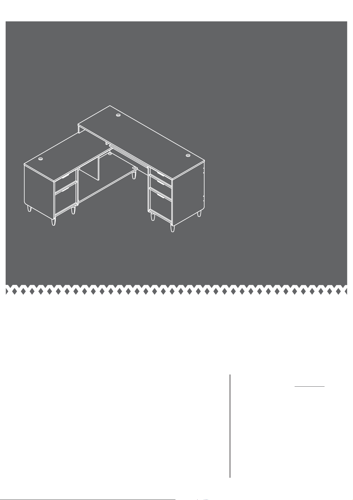
Return on Left
L-Shaped Desk
Clifton Place Collection | Model 5421120
Share your journey!
NOTE: THIS INSTRUCTION
BOOKLET CONTAINS IMPORTANT
SAFETY INFORMATION.
PLEASE READ AND KEEP FOR
FUTURE REFERENCE.
Page 2

Table of Contents Assembly Tools Required
Part Identifi cation
Hardware Identifi cation
Assembly Steps
Français
Español
Safety
59-65
66-72
73-74
Warranty
Part Identifi cation
2-3
4-5
6-58
75
No. 2 Phillips Screwdriver
Tip Shown Actual Size
Hammer
Not actual size
Electric drill with 3/16" bit
(ONLY in indicated step)
Now you know
our ABCs.
å While not all parts are labeled, some of the parts will have a label or an inked letter on the ede
to help distinuish similar parts from each other. Use this part identifi cation to help identify similar parts.
A RIGHT END (1)
B LEFT END (1)
C UPRIGHT (1)
D RETURN UPRIGHT (1)
E TOP (1)
F RETURN TOP (1)
G SHELF (2)
H SMALL BOTTOM (1)
I BOTTOM (1)
J RETURN SMALL BOTTOM (1)
K SMALL BACK (1)
L RETURN SMALL BACK (1)
M BACK (1)
N RETURN BACK (1)
O KEYBOARD SHELF (1)
P SHORT UPRIGHT (1)
Q LONG UPRIGHT (1)
R TOP RAIL (2)
S BRACE (2)
T RETURN BRACE (1)
U SMALL DRAWER FRONT (1)
V DRAWER FRONT (2)
W LARGE DRAWER FRONT (1)
X RETURN DRAWER FRONT (1)
Y SMALL RIGHT DRAWER SIDE (1)
Z SMALL LEFT DRAWER SIDE (1)
AA SMALL DRAWER BACK (1)
BB RIGHT DRAWER SIDE (2)
CC LEFT DRAWER SIDE (2)
DD DRAWER BACK (2)
EE DRAWER BOTTOM (4)
FF LARGE DRAWER BOTTOM (1)
GG LARGE RIGHT DRAWER SIDE (1)
HH LARGE LEFT DRAWER SIDE (1)
II LARGE DRAWER BACK (2)
JJ RETURN RIGHT DRAWER SIDE (1)
KK RETURN LEFT DRAWER SIDE (1)
LL LONG BOTTOM RAIL (2)
MM BOTTOM RAIL (4)
NN FOOT (11)
OO RETURN LEFT END (1)
PP RETURN RIGHT END (1)
Pae 2
Page 3
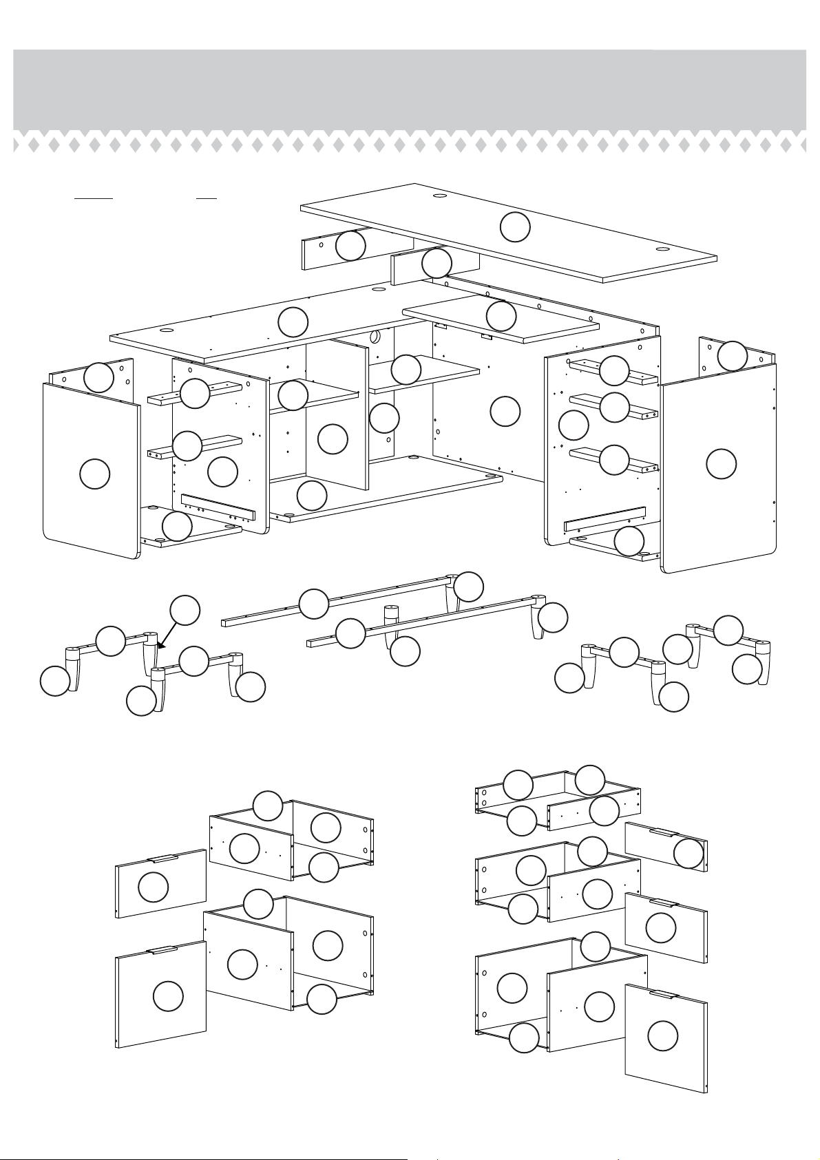
Part Identifi cation
å NOTE: Part PP will not be used
in the return on left assembly.
E
Q
P
NN
OO
L
MM
NN
J
NN
R
T
MM
F
O
K
G
R
G
N
M
S
B
C
D
S
A
I
H
NN
LL
LL
NN
NN
NN
NN
MM
MM
NN
NN
NN
Z
DD
BB
CC
EE
EE
CC
V
II
EE
AA
DD
Y
U
BB
V
JJ
KK
X
EE
HH
FF
II
GG
W
Pae 3
Page 4
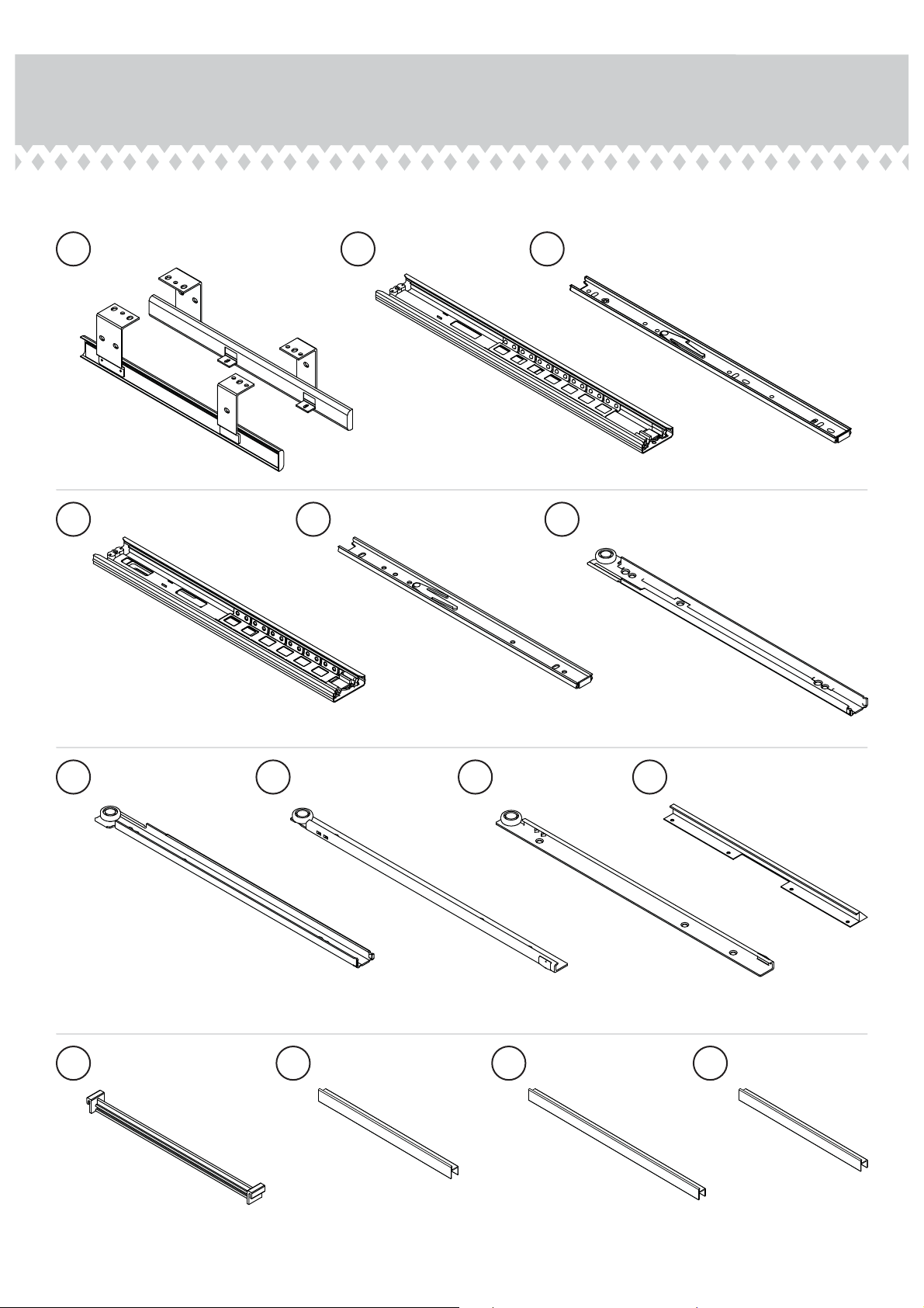
Hardware Identifi cation
å Screws are shown actual size. You may receive extra hardware with your unit.
1
SHELF SLIDER SET - 1
4
EXTENSION RAIL - 2
LONG EXTENSION
2
RAIL - 2
5
EXTENSION SLIDE - 2
(EXTENSION SET
(EXTENSION SET
SHOWN SEPARATED)
SHOWN SEPARATED)
LONG EXTENSION
3
SLIDE - 2
RIGHT CABINET
6
RAIL - 3
(EXTENSION SET
SHOWN SEPARATED)
LEFT CABINET
7
RAIL - 3
FILE
11
HANGER 4
RIGHT DRAWER
8
SLIDE - 3
BACK FILE
12
GLIDE - 1
LEFT DRAWER
9
SLIDE - 3
13
LONG FILE
GLIDE - 2
10
FRONT FILE
GLIDE 1
SHORT FILE
14
GLIDE - 2
Pae 4
Page 5
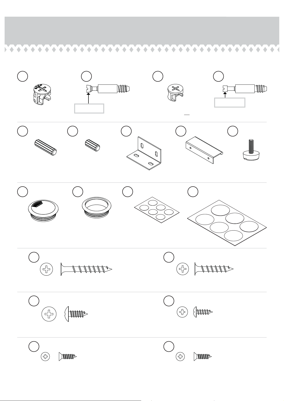
Hardware Identifi cation
å Screws are shown actual size. You may receive extra hardware with your unit.
å Screws are shown actual size. You may receive extra hardware with your unit.
LARGE HIDDEN
15
CAM - 65
LONG WOOD
19
DOWEL - 40
GROMMET
24
WITH CAP- 4
16
Anled head
SHORT WOOD
20
DOWEL - 12
25
GROMMET - 4
ANGLED HEAD
CAM SCREW - 65
21
26
SMALL HIDDEN
17
CAM - 20
BRACKET - 2
APPLIQUE CARD - 1
STRAIGHT HEAD
18
CAM SCREW - 20
Straiht head
(Do not open parts 17 and 18 until you
are ready to assemble the drawers.)
22
PULL - 5
LARGE
27
APPLIQUE CARD - 1
23
ADJUSTABLE
GLIDE - 11
28
BLACK 1-1/2" FLAT HEAD SCREW - 44
30
BLACK 9/16" LARGE HEAD SCREW -4
32
BLACK 1/2" FLAT HEAD SCREW - 36
29
BLACK 1-1/8" FLAT HEAD SCREW - 18
31
BLACK 1/2" PAN HEAD SCREW - 40
33
SILVER 1/2" FLAT HEAD SCREW - 10
Pae 5
Page 6
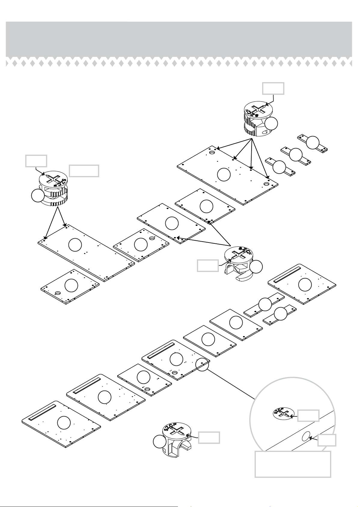
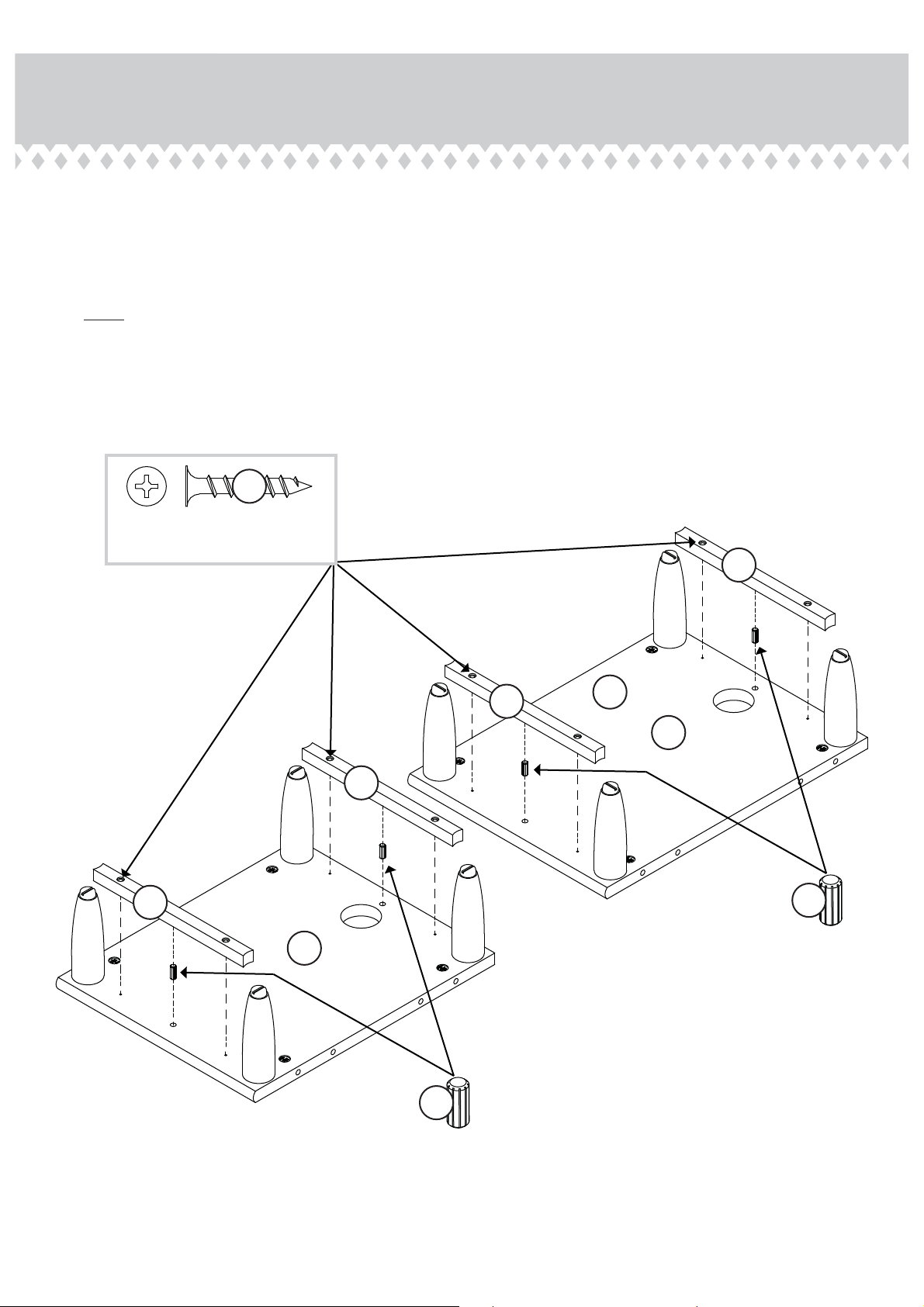
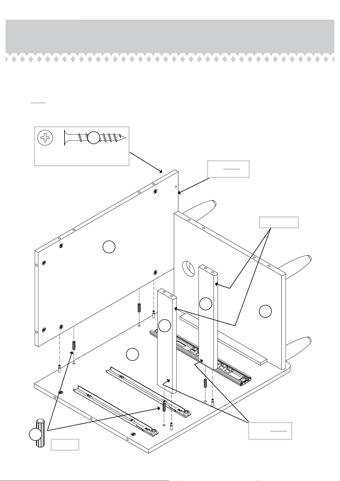
Step 1
Assemble your unit on a carpeted fl oor or on the empty carton
å
to avoid scratchin your unit or the fl oor.
Push fi fty-eiht HIDDEN CAMS (15) into the ENDS (A and B),
å
UPRIGHT (C), RETURN UPRIGHT (D), SHELVES (G),
BOTTOMS (H, I, and J), BACKS (K and L), RETURN
BACK (N), SHORT UPRIGHT (P), LONG UPRIGHT (Q),
BRACES (S and T), and RETURN LEFT END (OO).
Arrow
(58 used)
15
Arrow
15
T
S
S
N
L
K
I
H
J
Arrow
15
OO
Q
P
G
G
D
C
B
Pae 6
Arrow
A
15
Arrow
The arrow in the HIDDEN
CAM must point toward the
hole in the ede of the board.
Hole
Page 7
Step 2
Turn twenty ANGLED HEAD CAM SCREWS (16) into the
å
exact holes shown in the ENDS (A and B), UPRIGHT (C), and
RETURN LEFT END (OO).
Anled head
(20 used)
16
A
B
OO
C
Pae 7
Page 8
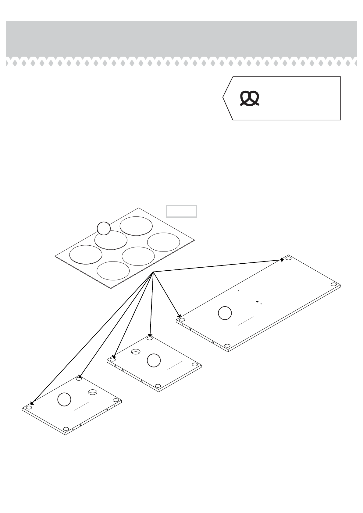
Step 3
Peel the STICKERS from the LARGE APPLIQUE CARD (27) and
å
stick one onto each metal insert in the BOTTOMS (H, I and J).
(12 used)
Some assembly
(and snacks) required.
27
I
Surface without
HIDDEN CAMS
J
Surface without
HIDDEN CAMS
H
Pae 8
Surface without
HIDDEN CAMS
Page 9
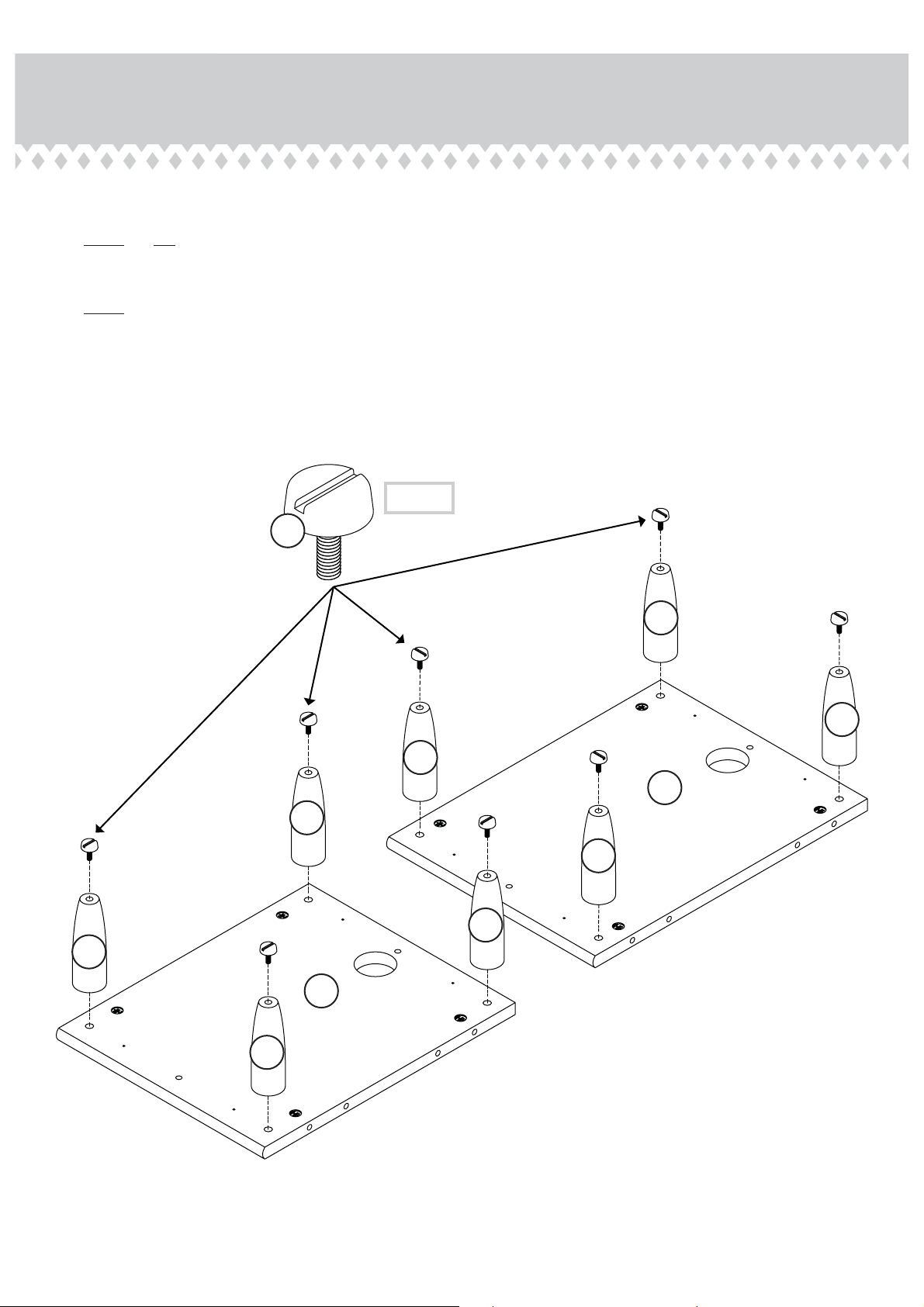
Step 4
Turn eiht FEET (NN) into the SMALL BOTTOMS (H and J).
å
NOTE: Do not overtihten the FEET.
å
Then, turn eiht ADJUSTABLE GLIDES (23) into the FEET (NN).
å
NOTE: Turn the ADJUSTABLE GLIDES completely in. Final
å
adjustments will be made after the unit is standin upriht.
(8 used)
23
NN
NN
NN
J
Surface with
HIDDEN CAMS
NN
NN
NN
NN
H
Surface with
HIDDEN CAMS
NN
Pae 9
Page 10
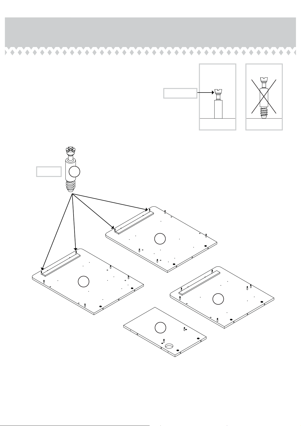
Step 5
Insert four SHORT WOOD DOWELS (20) into the SMALL
å
BOTTOMS (H and J).
Fasten four BOTTOM RAILS (MM) to the SMALL BOTTOMS (H
å
and J). Use eiht BLACK 1-1/8" FLAT HEAD SCREWS (29).
NOTE: Be sure the SHORT WOOD DOWELS in the SMALL
å
BOTTOMS insert into the BOTTOM RAILS.
29
BLACK 1-1/8" FLAT HEAD SCREW
(8 used in this step)
MM
MM
MM
MM
H
MM
20
J
20
Pae 10
Page 11
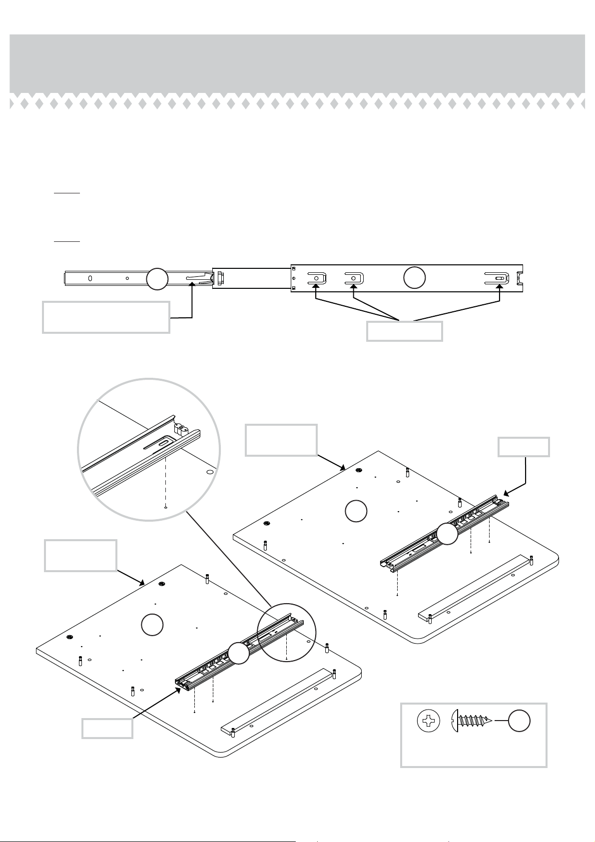
Step 6
Separate the LONG EXTENSION SLIDES (3) from the LONG EXTENSION RAILS (2) as shown in the enlared
å
diaram below. Be prepared, the parts are reasy.
Fasten two LONG EXTENSION RAILS (2) to the ENDS (A and B). Use six BLACK 1/2" PAN HEAD SCREWS (31).
å
NOTE: For each EXTENSION RAIL, turn a SCREW into the hole shown in the enlared diaram. Then, slide the inner
å
cartride of the EXTENSION RAIL in to fi nd the other holes that lines up with the holes in the ENDS. Turn a SCREW
into this hole.
NOTE: The LONG EXTENSION SLIDES will be used later for the LARGE DRAWER.
å
3
Push the black lever up and
pull the SLIDE from the RAIL.
Ede with
HIDDEN CAMS
Ede with
HIDDEN CAMS
Use these holes.
A
Surface with
HIDDEN CAMS
2
Open end
2
Open end
B
Surface with
HIDDEN CAMS
2
31
BLACK 1/2" PAN HEAD SCREW
(6 used in this step)
Pae 11
Page 12
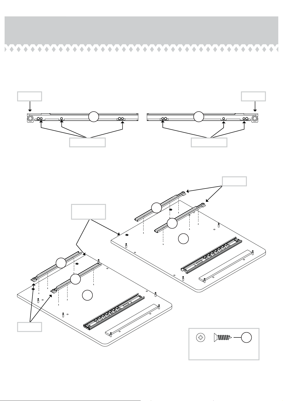
Step 7
Fasten the CABINET RAILS (6 and 7) to the ENDS (A and B).
å
Use twelve BLACK 1/2" FLAT HEAD SCREWS (32).
Roller end Roller end
7
Use these holes.
Ede with
HIDDEN CAMS
6
Use these holes.
Roller end
6
6
A
Surface with
HIDDEN CAMS
Roller end
Pae 12
7
7
B
Surface with
HIDDEN CAMS
32
BLACK 1/2" FLAT HEAD SCREW
(12 used in this step)
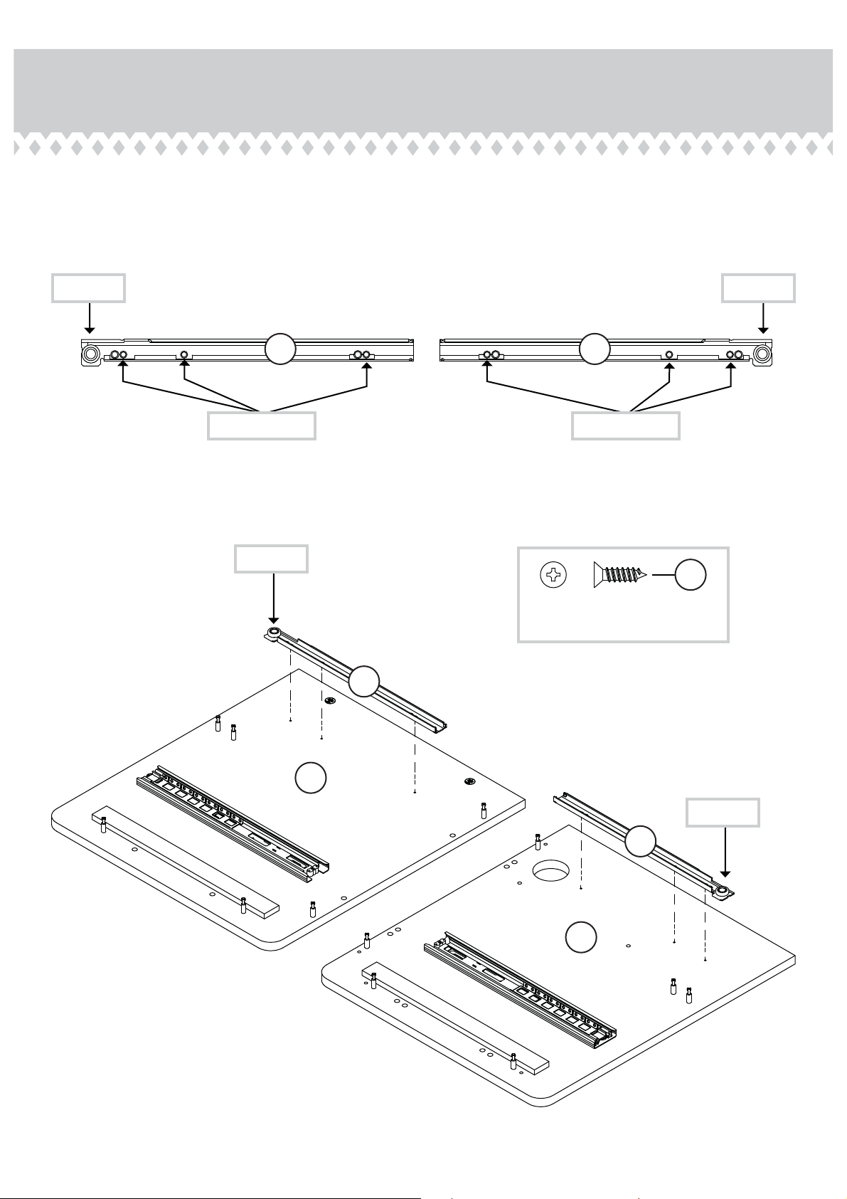
Page 13
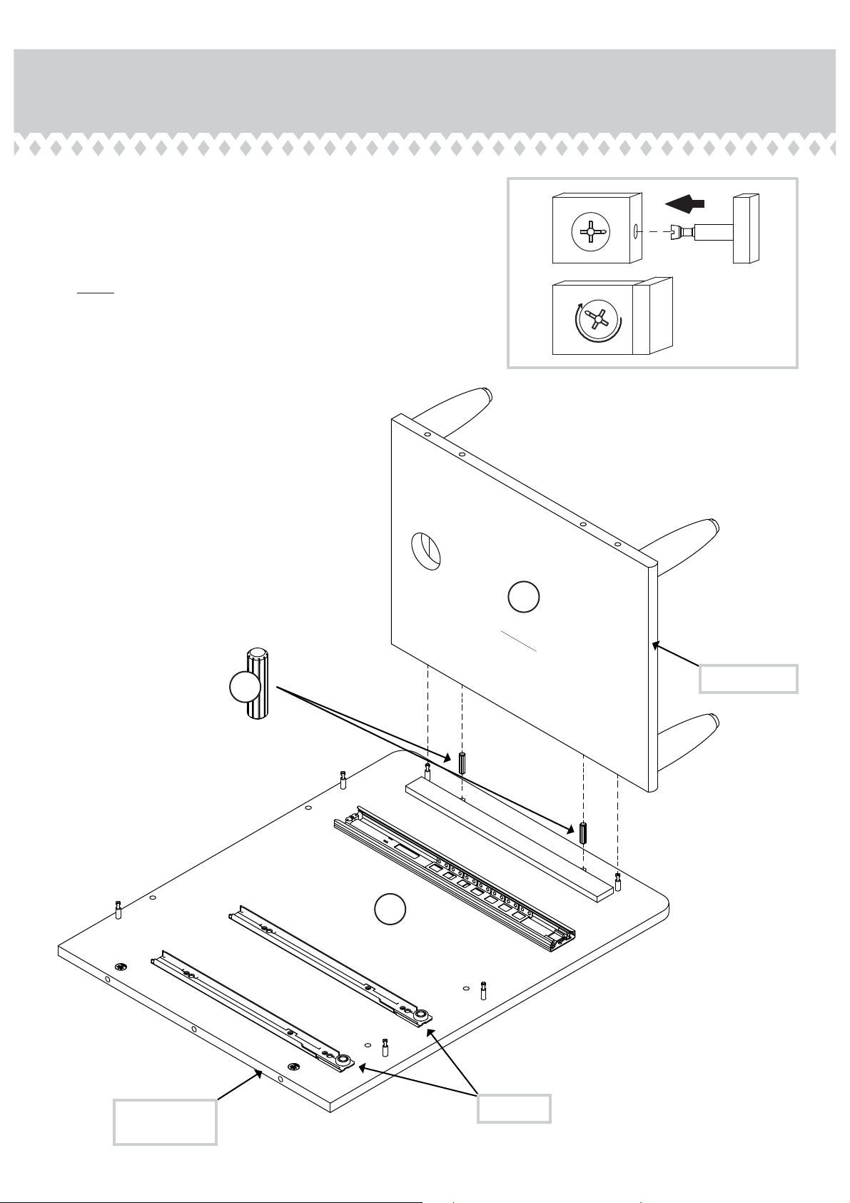
Step 8
Insert two LONG WOOD DOWELS (19) into the exact
å
holes shown in the LEFT END (B).
Fasten the SMALL BOTTOM (H) to the LEFT END (B).
å
Tihten two HIDDEN CAMS.
NOTE: Be sure the WOOD DOWELS in the LEFT END
å
insert into the holes in the SMALL BOTTOM.
1
2
Surface without FEET
H
19
Rounded ede
Surface with HIDDEN CAMS
B
Ede with
HIDDEN CAMS
Roller end
Pae 13
Page 14
Step 9
Insert four LONG WOOD DOWELS (19) into the exact holes shown in the LEFT END (B).
å
Fasten the SMALL BACK (K) and the BRACES (S) to the LEFT END (B). Tihten four HIDDEN CAMS.
å
NOTE: Be sure the LONG WOOD DOWELS in the LEFT END insert into the SMALL BACK and BRACES.
å
Fasten the SMALL BACK (K) to the SMALL BOTTOM (H). Use two BLACK 1-1/2" FLAT HEAD SCREWS (28).
å
28
BLACK 1-1/2" FLAT HEAD SCREW
(2 used in this step)
Ede without
HIDDEN CAMS
K
Surface with
HIDDEN CAMS
B
Rounded ede
S
H
S
19
Pae 14
Surface without
HIDDEN CAMS
(4 used)
Page 15
Step 10
Insert six LONG WOOD DOWELS (19) into the RIGHT END (A).
å
Fasten the RIGHT END (A) to the SMALL BOTTOM (H), SMALL
å
BACK (K), and BRACES (S). Tihten six HIDDEN CAMS.
NOTE: Be sure the LONG WOOD DOWELS in the RIGHT END
å
insert into the holes in the SMALL BOTTOM, SMALL BACK,
and BRACES.
Ede with
HIDDEN CAMS
Surface without
HIDDEN CAMS
K
A
19
H
19
S
S
Pae 15
Page 16
Step 11
Turn six ANGLED HEAD CAM SCREWS (16) into the exact
å
holes shown in the RETURN UPRIGHT (D).
16
Anled head
Pae 16
D
Page 17
Step 12
Separate the EXTENSION SLIDES (5) from the EXTENSION RAILS (4) as shown in the enlared diaram below. Be
å
prepared, the parts are reasy.
Fasten two EXTENSION RAILS (4) to the RETURN UPRIGHT (D) and RETURN LEFT END (OO). Use six BLACK 1/2"
å
PAN HEAD SCREWS (31).
NOTE: For each EXTENSION RAIL, turn a SCREW into the hole shown in the enlared diaram. Then, slide the inner
å
cartride of the EXTENSION RAIL in to fi nd the other holes that lines up with the holes in the UPRIGHT and END. Turn
a SCREW into this hole.
NOTE: The EXTENSION SLIDES will be used later for the RETURN DRAWER.
å
45
Push the black lever up and
pull the SLIDE from the RAIL.
Use these holes.
Open end
Ede with
HIDDEN CAMS
4
Surface with HIDDEN CAMS
OO
Unfi nished ede
4
Surface with CAM SCREWS
D
31
BLACK 1/2" PAN HEAD SCREW
(6 used in this step)
Open end
Pae 17
Page 18
Step 13
Fasten the CABINET RAILS (6 and 7) to the RETURN
å
UPRIGHT (D) and RETURN LEFT END (OO). Use six BLACK
1/2" FLAT HEAD SCREWS (32).
Roller end Roller end
7
Use these holes.
Roller end
7
Surface with HIDDEN CAMS
OO
6
Use these holes.
32
BLACK 1/2" FLAT HEAD SCREW
(6 used in this step)
Pae 18
Roller end
6
Surface with CAM SCREWS
D
Page 19

Step 14
Fasten the RETURN SMALL BACK (L) to the RETURN
å
SMALL BOTTOM (J). Use two BLACK 1-1/2" FLAT HEAD
SCREWS (28).
Ede without
HIDDEN CAMS
28
BLACK 1-1/2" FLAT HEAD SCREW
(2 used in this step)
Rounded ede
L
Surface with
HIDDEN CAMS
J
Surface without FEET
Pae 19
Page 20

Step 15
Insert four LONG WOOD DOWELS (19) into the exact
å
holes shown in the RETURN UPRIGHT (D).
Fasten the RETURN SMALL BOTTOM (J) and RETURN
å
SMALL BACK (L) to the RETURN UPRIGHT (D). Tihten
four HIDDEN CAMS.
NOTE: Be sure the LONG WOOD DOWELS in the
å
RETURN UPRIGHT insert into the holes in the RETURN
SMALL BOTTOM and RETURN SMALL BACK.
19
J
D
Surface with
CAM SCREWS
L
Surface with
HIDDEN CAMS
Pae 20
Open end
19
Unfi nished ede
Page 21

Step 16
Fasten the RETURN BRACE (T) to the RETURN UPRIGHT (D).
å
Tihten two HIDDEN CAMS.
Rounded ede
T
D
Surface without
HIDDEN CAMS
Pae 21
Page 22

Step 17
Insert four LONG WOOD DOWELS (19) into the RETURN
å
LEFT END (OO).
Fasten the RETURN LEFT END (OO) to the RETURN SMALL
å
BOTTOM (J), RETURN SMALL BACK (L), and RETURN
BRACE (T). Tihten six HIDDEN CAMS.
NOTE: Be sure the LONG WOOD DOWELS in the RETURN
å
LEFT END insert into the holes in the RETURN SMALL
BOTTOM, RETURN SMALL BACK, and RETURN BRACE.
OO
19
Surface without
CAM SCREWS
Ede with
HIDDEN CAMS
19
J
L
Pae 22
T
Page 23

Step 18
Fasten the UPRIGHT (C) to one of the SHELVES (G). Use
å
two BLACK 1-1/2" FLAT HEAD SCREWS (28).
Finished ede
G
Surface with
HIDDEN CAMS
Finished ede
C
Surface with
HIDDEN CAMS
28
BLACK 1-1/2" FLAT HEAD SCREW
(2 used in this step)
Pae 23
Page 24

Step 19
Fasten the other SHELF (G) to the UPRIGHT (C). Tihten
å
two HIDDEN CAMS.
Finished ede
C
C
G
Surface with
HIDDEN CAMS
Pae 24
Page 25

Step 20
Fasten the BOTTOM (I) to the UPRIGHT (C). Use two
å
BLACK 1-1/2" FLAT HEAD SCREWS (28).
Rounded ede
Surface with
HIDDEN CAMS
I
C
28
BLACK 1-1/2" FLAT HEAD SCREW
(2 used in this step)
Pae 25
Page 26

Step 21
Carefully turn the assembly over onto its front edes.
å
Insert four LONG WOOD DOWELS (19) into the exact holes shown in the RETURN BACK (N).
å
Fasten the RETURN BACK (N) to the UPRIGHT (C), SHELVES (G), and BOTTOM (I). Use ten BLACK 1-1/2" FLAT HEAD
å
SCREWS (28).
NOTE: Be sure the LONG WOOD DOWELS in the RETURN BACK insert into the holes in the UPRIGHT and SHELVES.
å
19
28
BLACK 1-1/2" FLAT HEAD SCREW
(10 used in this step)
G
Surface without
HIDDEN CAMS
N
Lare hole
Surface with
HIDDEN CAMS
N
Lare hole
Pae 26
C
G
I
Page 27

Step 22
Carefully lay the assembly onto its back.
å
Turn three FEET (NN) into the BOTTOM (I).
å
NOTE: Do not overtihten the FEET.
å
Then, turn three ADJUSTABLE GLIDES (23) into the FEET (NN).
å
NOTE: Turn the ADJUSTABLE GLIDES completely in. Final
å
adjustments will be made after the unit is standin upriht.
NN
NN
I
NN
23
Pae 27
Page 28

Step 23
Insert four SHORT WOOD DOWELS (20) into the BOTTOM (I).
å
Fasten two LONG BOTTOM RAILS (LL) to the BOTTOM (I). Use six
å
BLACK 1-1/8" FLAT HEAD SCREWS (29).
NOTE: Be sure the SHORT WOOD DOWELS in the BOTTOM
å
insert into the holes in the LONG BOTTOM RAILS.
(4 used)
20
LL
Pae 28
I
LL
29
BLACK 1-1/8" FLAT HEAD SCREW
(6 used in this step)
Page 29

Step 24
Turn six ANGLED HEAD CAM SCREWS (16) into the exact
å
holes shown in the RETURN UPRIGHT (D).
Insert four LONG WOOD DOWELS (19) into the exact holes
å
shown in the RETURN UPRIGHT (D).
Anled head
(6 used)
D
16
19
19
Pae 29
Page 30

Step 25
NOTE: You may need someone's help in this step.
å
Fasten the RETURN UPRIGHT (D) to the SHELF (G),
å
BOTTOM (I), and RETURN BACK (N). Tihten six
HIDDEN CAMS.
NOTE: Be sure the LONG WOOD DOWELS in the
å
RETURN UPRIGHT insert into the holes in the SHELF,
BOTTOM, and RETURN BACK.
D
G
I
N
Pae 30
Page 31

Step 26
NOTE: Be sure to position the RETURN TOP (F) exactly
å
as shown.
Turn twelve ANGLED HEAD CAM SCREWS (16) into the
å
exact holes shown in the RETURN TOP (F).
16
Anled head
Lare hole
F
Surface with
more holes
Pae 31
Page 32

Step 27
NOTE: Be sure to position the RETURN TOP exactly as shown.
å
Insert two SHORT WOOD DOWELS (20) into the exact holes shown in the RETURN TOP (F).
å
Fasten a TOP RAIL (R) to the RETURN TOP (F). Use two BLACK 1-1/8" FLAT HEAD SCREWS (29).
å
NOTE: Be sure the SHORT WOOD DOWELS in the RETURN TOP insert into the holes in the TOP RAIL.
å
Fasten two BRACKETS (21) to the RETURN TOP (F). Use four BLACK 1/2" PAN HEAD SCREWS (31).
å
With a drill and 3/16" drill bit, fi nish drillin throuh the exact four holes shown in the RETURN TOP (F).
å
29
CAUTION
Make sure you have
packin foam or
throw away material
underneath the
return top near the
drill area.
Drill throuh these
four holes.
F
Surface with
CAM SCREWS
BLACK 1-1/8" FLAT HEAD SCREW
(2 used in this step)
Lare hole
R
20
Rounded ede
21
Pae 32
31
BLACK 1/2" PAN HEAD SCREW
(4 used for the BRACKETS)
Page 33

Step 28
Fasten the UPRIGHTS (P and Q) to the RETURN TOP (F).
å
Use four BLACK 1-1/2" FLAT HEAD SCREWS (28).
Ede with
HIDDEN CAMS
Surface with
Q
HIDDEN CAMS
Surface without
P
HIDDEN CAMS
F
R
Lare hole
Surface with
CAM SCREWS
28
BLACK 1-1/2" FLAT HEAD SCREW
(4 used in this step)
Pae 33
Page 34

Step 29
With someone's help, carefully stand the return assembly
å
upriht and place it near its fi nal location.
Insert two LONG WOOD DOWELS (19) into the exact holes shown
å
in the RETURN UPRIGHT (D) and RETURN LEFT END (OO).
Fasten the RETURN TOP (F) to the UPRIGHTS (C and D),
å
RETURN SMALL BACK (L), RETURN BACK (N), and RETURN
LEFT END (OO). Tihten twelve HIDDEN CAMS.
NOTE: Be sure the WOOD DOWELS in the RETURN UPRIGHT
å
and RETURN LEFT END inserts into the holes in the
RETURN TOP.
Lare hole
Pro Tip: Lift with your
les. And, you know,
your arms.
19
F
C
N
L
D
Pae 34
OO
Page 35

Step 30
NOTE: Be sure to position the BACK (M) exactly as shown.
å
Turn four ANGLED HEAD CAM SCREWS (16) into the exact
å
holes shown in the BACK (M).
Push seven HIDDEN CAMS (15) into the exact holes shown
å
in the BACK (M).
Peel two APPLIQUES from the APPLIQUE CARD (26) and
å
stick them over the two lare holes in the BACK (M).
Arrow
15
Anled head
Arrow
15
26
M
16
Pae 35
Page 36

Step 31
NOTE: You may need someone's help in this step.
å
Insert four LONG WOOD DOWELS (19) into the exact holes
å
shown in the BACK (M).
Fasten the BACK (M) to the BOTTOM (I) and RETURN
å
BACK (N). Tihten four HIDDEN CAMS.
NOTE: Be sure the WOOD DOWELS in the BACK inserts
å
into the holes in the BOTTOM and RETURN BACK
Fasten the BACK (M) to the SHELF (G). Use two BLACK
å
1-1/2" FLAT HEAD SCREWS (28).
Fasten the RETURN TOP (F) to the BACK (M). Use
å
four BLACK 1/2" PAN HEAD SCREWS (31) throuh the
BRACKETS on the RETURN TOP and into the BACK.
28
BLACK 1-1/2" FLAT HEAD SCREW
(2 used in this step)
(4 used)
F
I
19
G
Ede with
HIDDEN CAMS
M
Surface with
HIDDEN CAMS
Pae 36
N
31
BLACK 1/2" PAN HEAD SCREW
(4 used for the BRACKETS)
Page 37

Step 32
Turn two ANGLED HEAD CAM SCREWS (16) into the exact
å
holes shown in the LEFT END (B).
Insert two LONG WOOD DOWELS (19) into the exact holes
å
shown in the LEFT END (B).
16
Anled head
19
B
Pae 37
Page 38

Step 33
NOTE: You may need someone's help in this step.
å
Fasten the LEFT END (B) to the BACK (M). Tihten two
å
HIDDEN CAMS.
NOTE: Be sure the WOOD DOWELS in the LEFT END
å
insert into the holes in the BACK
M
B
Pae 38
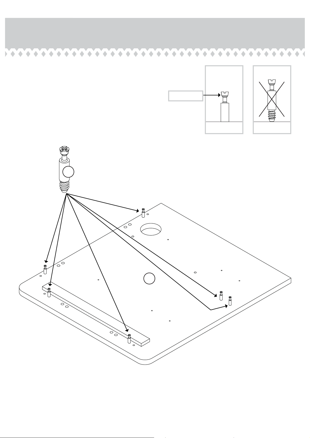
Page 39

Step 34
NOTE: Be sure to position the TOP (E) exactly as shown.
å
Turn fi fteen ANGLED HEAD CAM SCREWS (16) into the
å
exact holes shown in the TOP (E).
Then, insert two SHORT WOOD DOWELS (20) into the
å
exact holes shown in the TOP (E).
Fasten the remainin TOP RAIL (R) to the TOP (E). Use two
å
BLACK 1-1/8" FLAT HEAD SCREWS (29).
NOTE: Be sure the SHORT WOOD DOWELS in the TOP
å
insert into the holes in the TOP RAIL.
29
Anled head
(15 used)
Surface with
more holes
16
E
Lare hole
BLACK 1-1/8" FLAT HEAD SCREW
(2 used in this step)
R
20
Rounded ede
Surface with
CAM SCREWS
E
Lare hole
Pae 39
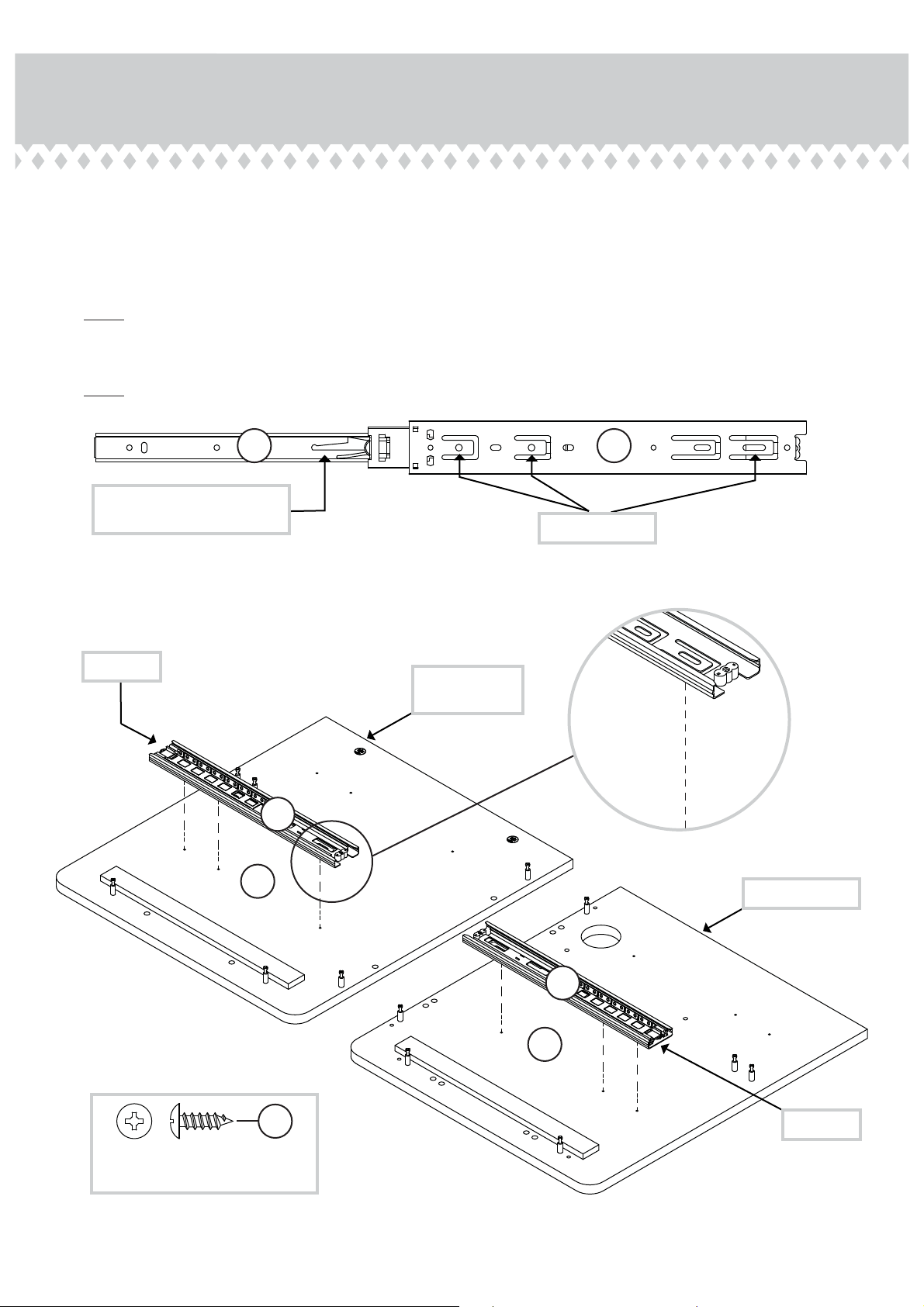
Page 40

Step 35
Fasten the SHELF SLIDER SET (1) to the TOP (E). Use
å
four BLACK 9/16" LARGE HEAD SCREWS (30).
NOTE: Be sure to use the center hole in the
å
SHELF SLIDERS.
30
BLACK 9/16" LARGE HEAD SCREW
(4 used in this step)
R
The tabs on the SHELF SLIDERS
should be closer to this ede.
1
E
1
Pae 40
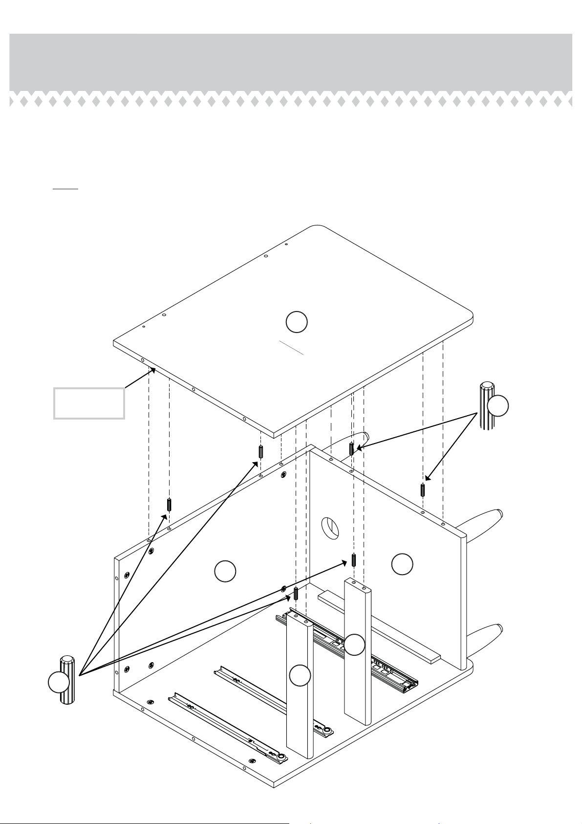
Page 41

Step 36
Fasten the KEYBOARD SHELF (O) to the SHELF
å
SLIDERS on the TOP (E). Use four BLACK 9/16" PAN
HEAD SCREWS (31).
BLACK 1/2" PAN HEAD SCREW
(4 used in this step)
31
R
Surface with holes
Rounded ede
O
E
Pae 41
Page 42

Step 37
NOTE: You may need someone's help in this step.
å
Insert four LONG WOOD DOWELS (19) into the exact holes
å
shown in the ENDS (A and B) and UPRIGHTS (P and Q).
Fasten the TOP (E) to the ENDS (A and B), BACKS (K and M),
å
and UPRIGHTS (P and Q). Tihten fi fteen HIDDEN CAMS.
NOTE: Be sure the WOOD DOWELS in the ENDS and
å
UPRIGHTS inserts into the holes in the TOP.
19
Lare hole
E
Q
P
M
K
B
A
Pae 42
19
Page 43

Step 38
Insert twenty SMALL HIDDEN CAMS (17) into the
å
DRAWER SIDES (Y, Z, BB, CC, GG, HH, JJ, and KK).
CC
CC
BB
KK
BB
Z
JJ
Y
HH
GG
17
The arrow in the HIDDEN
CAM must point toward the
hole in the ede of the board.
Arrow
(20 used)
Pae 43
Page 44

Step 39
Turn twenty STRAIGHT HEAD CAM SCREWS (18) into
å
the DRAWER FRONTS (U, V, W, and X).
Straiht head
V
(20 used)
18
U
V
W
X
Pae 44
Page 45

Step 40
12
Y
1
2
EE
Unfi nished
surface
With the palm of
your hand, tap
the DRAWER
BOTTOM down
into the roove.
Y
Z
Z
U
Groove
Fasten the SMALL DRAWER SIDES (Y and Z) to the
å
SMALL DRAWER FRONT (U). Tihten four HIDDEN CAMS.
Be sure the DRAWER
BOTTOM inserts into the
DRAWER FRONT roove.
Slide the DRAWER BOTTOM (EE) into the rooves in the
å
SMALL DRAWER SIDES (Y and Z) and SMALL DRAWER
FRONT (U).
U
3
Be sure the DRAWER
BOTTOM inserts into the
DRAWER BACK roove.
BLACK 1-1/2" FLAT HEAD SCREW
(4 used in this step)
AA
28
Y
EE
Z
Fasten the SMALL DRAWER BACK (AA) to the SMALL DRAWER SIDES (Y and Z). Use four BLACK 1-1/2" FLAT HEAD
å
SCREWS (28).
NOTE: Be sure the DRAWER BOTTOM (EE) inserts into the roove of the SMALL DRAWER BACK (AA).
å
Pae 45
Page 46

Step 41
Fasten the DRAWER SLIDES (8 and 9) to the SMALL
å
DRAWER SIDES (Y and Z). Use six BLACK 1/2" FLAT
HEAD SCREWS (32).
Fasten a PULL (22) to the SMALL DRAWER FRONT (U).
å
Use two SILVER 1/2" FLAT HEAD SCREWS (33).
22
32
BLACK 1/2" FLAT HEAD SCREW
(6 used for the DRAWER SLIDES)
9
Roller end
Z
U
Y
8
33
SILVER 1/2" FLAT HEAD SCREW
(2 used for the PULL)
Roller end
Pae 46
Page 47

Step 42
12
BB
CC
V
Groove
Fasten the DRAWER SIDES (BB and CC) to the DRAWER
å
FRONT (V). Tihten four HIDDEN CAMS.
BB
Be sure the DRAWER
BOTTOM inserts into the
DRAWER FRONT roove.
Slide the DRAWER BOTTOM (EE) into the rooves in the
å
DRAWER SIDES (BB and CC) and DRAWER FRONT (V).
EE
Unfi nished
surface
V
With the palm of
your hand, tap
the DRAWER
BOTTOM down
into the roove.
CC
3
BLACK 1-1/2" FLAT HEAD SCREW
(8 used in this step)
Be sure the DRAWER
BOTTOM inserts into the
DRAWER BACK roove.
BB
Fasten the DRAWER BACK (DD) to the DRAWER SIDES (BB and CC). Use four BLACK 1-1/2" FLAT HEAD SCREWS (28).
å
NOTE: Be sure the DRAWER BOTTOM (EE) inserts into the roove of the DRAWER BACK (DD).
å
Repeat this step for the remainin DRAWER FRONT (V), DRAWER SIDES (BB and CC), DRAWER BACK (DD), and
å
DRAWER BOTTOM (EE).
DD
EE
CC
28
Pae 47
Page 48

Step 43
Fasten the DRAWER SLIDES (8 and 9) to the DRAWER
å
SIDES (BB and CC). Use six BLACK 1/2" FLAT HEAD
SCREWS (32).
Fasten a PULL (22) to the DRAWER FRONT (V). Use two
å
SILVER 1/2" FLAT HEAD SCREWS (33).
Repeat this step for the other drawer.
å
32
22
BLACK 1/2" FLAT HEAD SCREW
(12 used for the DRAWER SLIDES)
9
CC
Roller end
U
BB
Pae 48
8
33
SILVER 1/2" FLAT HEAD SCREW
(4 used for the PULLS)
Roller end
Page 49

Step 44
12
FF
Unfi nished
GG
HH
surface
GG
With the palm of
your hand, tap
the DRAWER
BOTTOM down
into the roove.
HH
W
W
Be sure the DRAWER
Groove
Fasten the LARGE DRAWER SIDES (GG and HH) to
å
the LARGE DRAWER FRONT (W). Tihten four
HIDDEN CAMS.
BOTTOM inserts into the
DRAWER FRONT roove.
Slide the LARGE DRAWER BOTTOM (FF) into the rooves
å
in the LARGE DRAWER SIDES (GG and HH) and LARGE
DRAWER FRONT (W).
3
BLACK 1-1/2" FLAT HEAD SCREW
(4 used in this step)
II
Be sure the DRAWER
BOTTOM inserts into the
DRAWER BACK roove.
GG
Fasten the LARGE DRAWER BACK (II) to the LARGE DRAWER SIDES (GG and HH). Use four BLACK 1-1/2" FLAT
å
HEAD SCREWS (28).
FF
HH
28
NOTE: Be sure the LARGE DRAWER BOTTOM (FF) inserts into the roove of the LARGE DRAWER BACK (II).
å
Pae 49
Page 50

Step 45
Fasten two LONG EXTENSION SLIDES (3) to the LARGE
å
DRAWER SIDES (GG and HH). Use six BLACK 1/2" PAN HEAD
SCREWS (31).
Fasten a PULL (22) to the LARGE DRAWER FRONT (W). Use
å
two SILVER 1/2" FLAT HEAD SCREWS (33).
Open end
22
Use these holes.
3
W
GG
HH
Open end
3
33
SILVER 1/2" FLAT HEAD SCREW
(2 used for the PULL)
31
Open end
BLACK 1/2" PAN HEAD SCREW
(6 used for the EXTENSION SLIDES)
Pae 50
Page 51

Step 46
Push the LONG FILE GLIDES (13) onto the LARGE
å
DRAWER SIDES (GG and HH).
Slide two FILE HANGERS (11) onto the LONG FILE
å
GLIDES on the LARGE DRAWER SIDES (GG and HH).
11
13
GG
11
13
HH
Pae 51
Page 52

Step 47
Fasten the FRONT FILE GLIDE (10) to the RETURN
å
DRAWER FRONT (X). Use four BLACK 1/2" PAN HEAD
SCREWS (31).
31
BLACK 1/2" PAN HEAD SCREW
(4 used in this step)
10
X
Pae 52
Page 53

Step 48
12
EE
JJ
KK
Unfi nished
surface
JJ
With the palm of
your hand, tap
the DRAWER
BOTTOM down
into the roove.
KK
X
X
Be sure the DRAWER
Groove
Fasten the RETURN DRAWER SIDES (JJ and KK) to
å
the RETURN DRAWER FRONT (X). Tihten four
HIDDEN CAMS.
BOTTOM inserts into the
DRAWER FRONT roove.
Slide the DRAWER BOTTOM (EE) into the rooves in the
å
RETURN DRAWER SIDES (JJ and KK) and RETURN
DRAWER FRONT (X).
3
BLACK 1-1/2" FLAT HEAD SCREW
(4 used in this step)
II
Be sure the DRAWER
BOTTOM inserts into the
DRAWER BACK roove.
JJ
Fasten the LARGE DRAWER BACK (II) to the RETURN DRAWER SIDES (JJ and KK). Use four BLACK 1-1/2" FLAT
å
HEAD SCREWS (28).
EE
KK
28
NOTE: Be sure the DRAWER BOTTOM (EE) inserts into the roove of the LARGE DRAWER BACK (II).
å
Pae 53
Page 54

Step 49
Fasten two EXTENSION SLIDES (5) to the RETURN DRAWER
å
SIDES (JJ and KK). Use six BLACK 1/2" PAN HEAD SCREWS (31).
Fasten a PULL (22) to the RETURN DRAWER FRONT (X). Use two
å
SILVER 1/2" FLAT HEAD SCREWS (33).
Open end
22
Use these holes.
5
X
KK
Open end
JJ
5
33
SILVER 1/2" FLAT HEAD SCREW
Open end
31
(2 used for the PULL)
BLACK 1/2" PAN HEAD SCREW
(6 used for the EXTENSION SLIDES)
Pae 54
Page 55

Step 50
Push the BACK FILE GLIDE (12) onto the LARGE DRAWER BACK (II).
å
Push the SHORT FILE GLIDES (14) onto the RETURN DRAWER SIDES (JJ and KK).
å
Slide the FILE HANGERS (11) onto the FILE GLIDES on the RETURN DRAWER FRONT (X) and LARGE DRAWER BACK (II).
å
NOTE: The FILE HANGERS can also be placed on the FILE GLIDES on the RETURN DRAWER SIDES (JJ and KK).
å
14
12
X
JJ
14
KK
II
11
11
X
II
Pae 55
Page 56

Step 51
Insert four GROMMETS (25) into the lare holes in
å
the UPRIGHTS (C and D) and RETURN BACK (N).
Insert four GROMMETS WITH CAPS (24) into the
å
lare holes in the TOPS (E and F).
24
E
F
N
25
(4 used)
Pae 56
Page 57

Step 52
Position your unit in its fi nal location.
å
NOTE: To raise a corner of the unit, turn the ADJUSTABLE
å
GLIDE counter-clockwise. To lower a corner, turn the
ADJUSTABLE GLIDE clockwise.
To insert the DRAWERS (U and V) into your unit, tip the
å
front of the drawers down and drop the rollers on the
drawers behind the rollers on the unit.
To insert the LARGE DRAWERS (W and X) into your unit,
å
line up the EXTENSION SLIDES on the drawers with the
EXTENSION RAILS on the unit and push the drawers into
the unit until the drawers are fully inserted. The drawers
will push in hard until they are all the way in, then they will
slide in and out easier.
V
Make any needed adjustments to the
ADJUSTABLE GLIDES to level your unit.
U
V
X
W
Pae 57
Page 58

Step 53
Peel the STICKERS from the APPLIQUE CARD (26) and stick them onto
å
each visible hole, HIDDEN CAM, or over the head of each visible SCREW.
NOTE: Please read the back paes of the instruction booklet for important
å
safety information.
This completes assembly. Clean with your favorite furniture polish or a
å
damp cloth. Wipe dry.
26
20 lbs.
To cover visible holes,
HIDDEN CAMS, or over
the heads of SCREWS.
50 lbs.
40 lbs.
10 lbs.
30 lbs. total
15 lbs.
20 lbs.
SHELF
25 lbs. each
Pae 58
30 lbs.
30 lbs.
Page 59

WARNING
Please use your furniture correctly and safely. Improper use can cause safety hazards,
or damae to your furniture or household items. Carefully read the following chart.
Look out for: What can happen: How to avoid the problem:
• Overloaded shelves or drawers.
• Impr
oper loadin can cause the product
to be top-heavy.
• Risk of injury.
• Top-heavy furniture can tip over.
• Overloaded shelves and drawers can
break.
• Never exceed the weiht limits shown in
the instructions.
• Work from bottom to top when loadin
shelves and drawers. Place the heavier
items on the lower shelves or in lower
drawers.
• Improperly movin furniture that is not
desined and equipped with casters.
• Placin TVs on furniture items that are
not desined to support a television is
hazardous.
• Furniture can tip over or break if
improperly moved.
• Physical injury. Furniture can be very
heavy.
• Breakae of tops - particularly with
double pedestal furniture (drawers at both
ends).
• Risk of injury or death. TVs can be very
heavy. Plus the weiht and location of the
picture tube tends to make TVs unbalanced
and prone to tippin forward.
• Unload shelves and drawers from top to
bottom before movin the unit.
• Do not push furniture, especially on a
carpeted fl oor. Have a friend help you lift
the item and set it in place.
• Provide support to the center section of
the top when liftin the furniture.
• This product is not desined to support a
television.
 Loading...