

www.teknikoffice.co.uk
Teknik
For things 'n such.
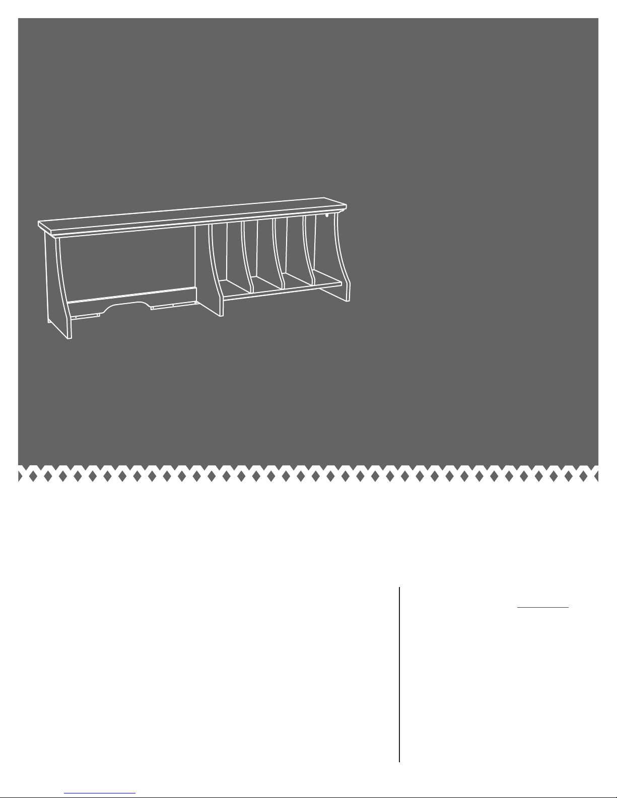
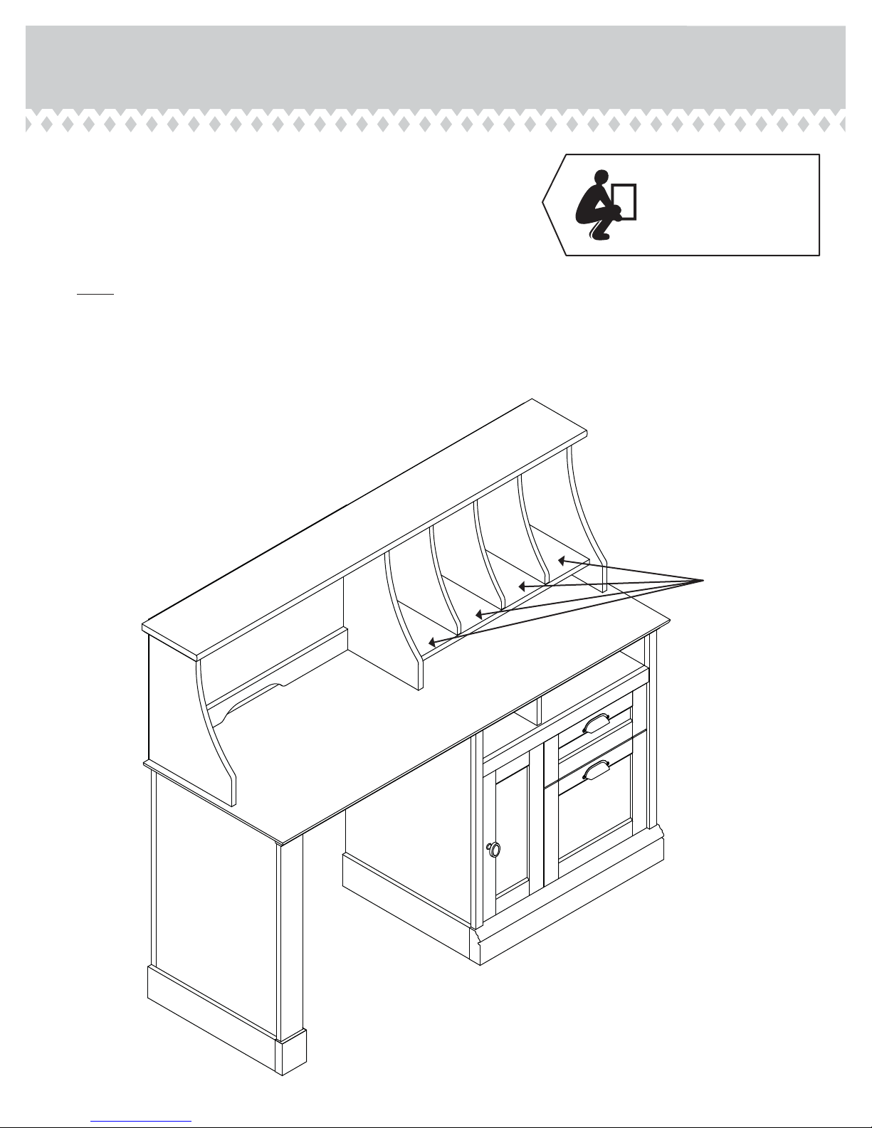
Hutch for Scribed Oak Storage Desk (5418294)
5418295
NOTE: THIS INSTRUCTION
BOOKLET CONTAINS IMPORTANT
SAFETY INFORMATION.
PLEASE READ AND KEEP FOR
FUTURE REFERENCE.
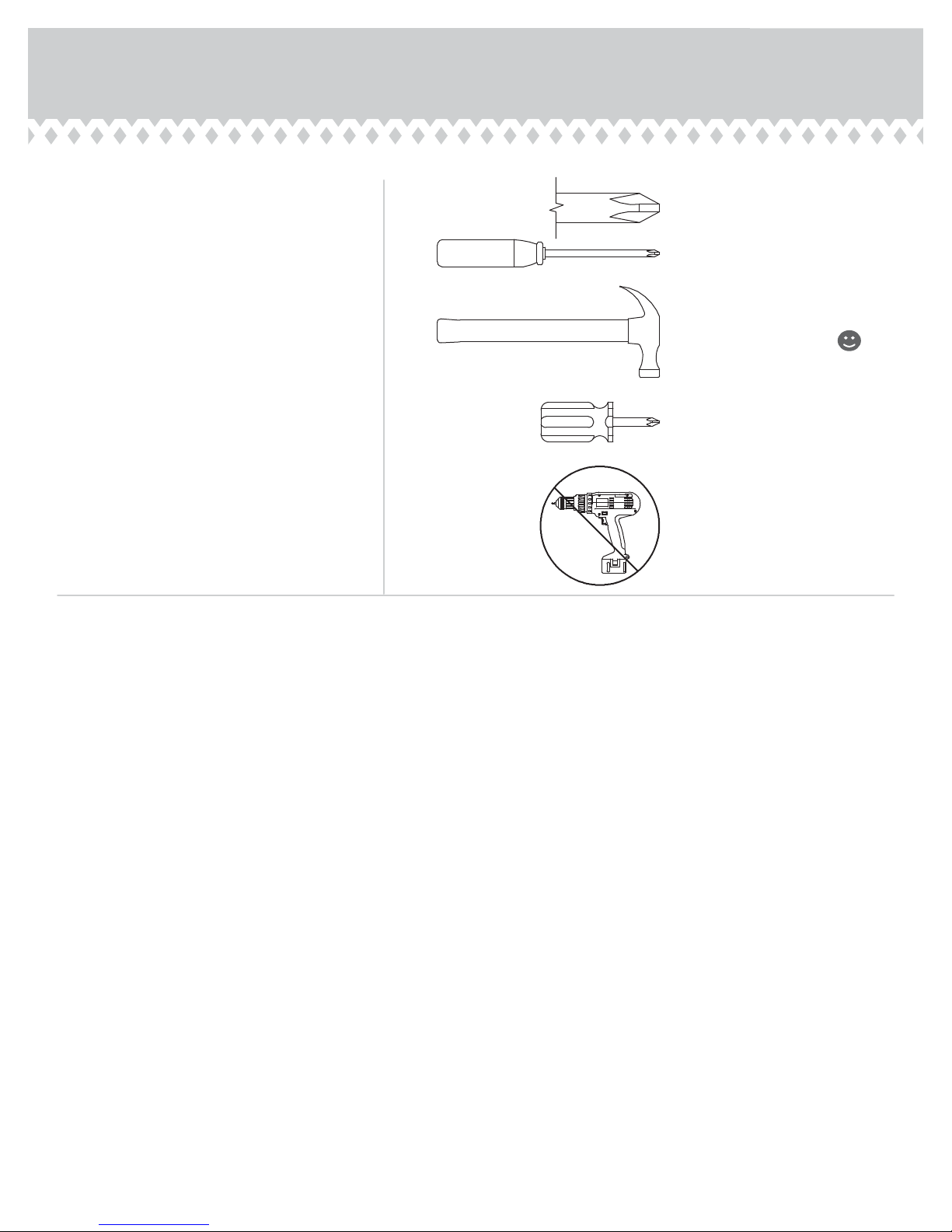
Table of Contents Assembly Tools Required
Part Identifi cation
Hardware Identifi cation
Assembly Steps
Safety
5-17
18
3
No. 2 Phillips Screwdriver
4
Tip Shown Actual Size
Hammer
Not actual size
Short Screwdriver
Skip the power trip.
This time.
Page 2
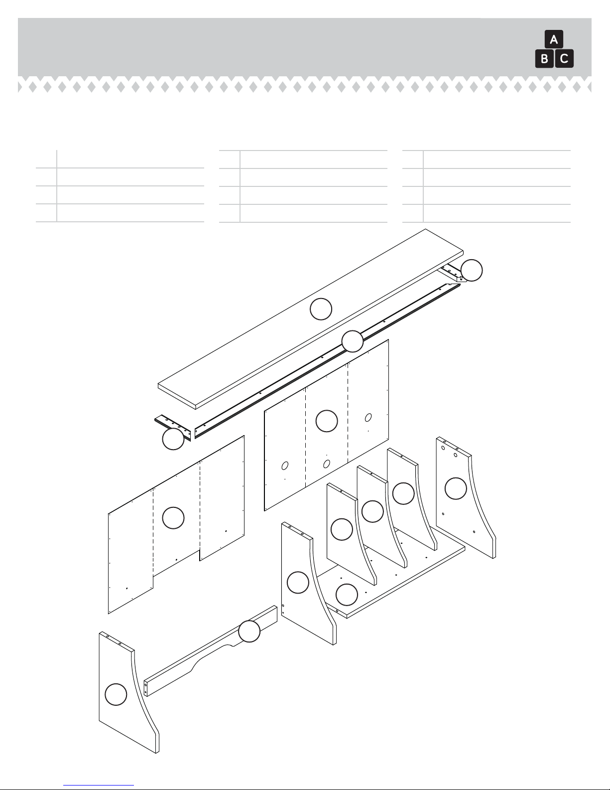
Part Identifi cation
å While not all parts are labeled, some of the parts will have a label or an inked letter on the edge
to help distinguish similar parts from each other. Use this part identifi cation to help identify similar parts.
Now you know
our ABCs.
A RIGHT END (1)
B LEFT END (1)
C UPRIGHT (1)
D TOP (1)
E SHELF (1)
F RIGHT BACK (1)
G LEFT BACK (1)
H DIVIDER (3)
I SKIRT (1)
J FRONT MOLDING (1)
K RIGHT MOLDING (1)
L LEFT MOLDING (1)
K
D
J
F
L
G
B
H
A
H
H
C
E
I
Page 3

Hardware Identifi cation
å Screws are shown actual size. You may receive extra hardware with your unit.
1F
HIDDEN CAM - 12
2F
CAM DOWEL - 12
MOLDING
17F
CONNECTOR - 2
1N
NAIL - 36
1S
BLACK 9/16" LARGE HEAD SCREW - 3
7S
BLACK 1-1/4" FLAT HEAD SCREW - 9
36P
CAM COVER - 10
1R
METAL PIN - 11
2S
BLACK 1-7/8" FLAT HEAD SCREW - 3
Page 4
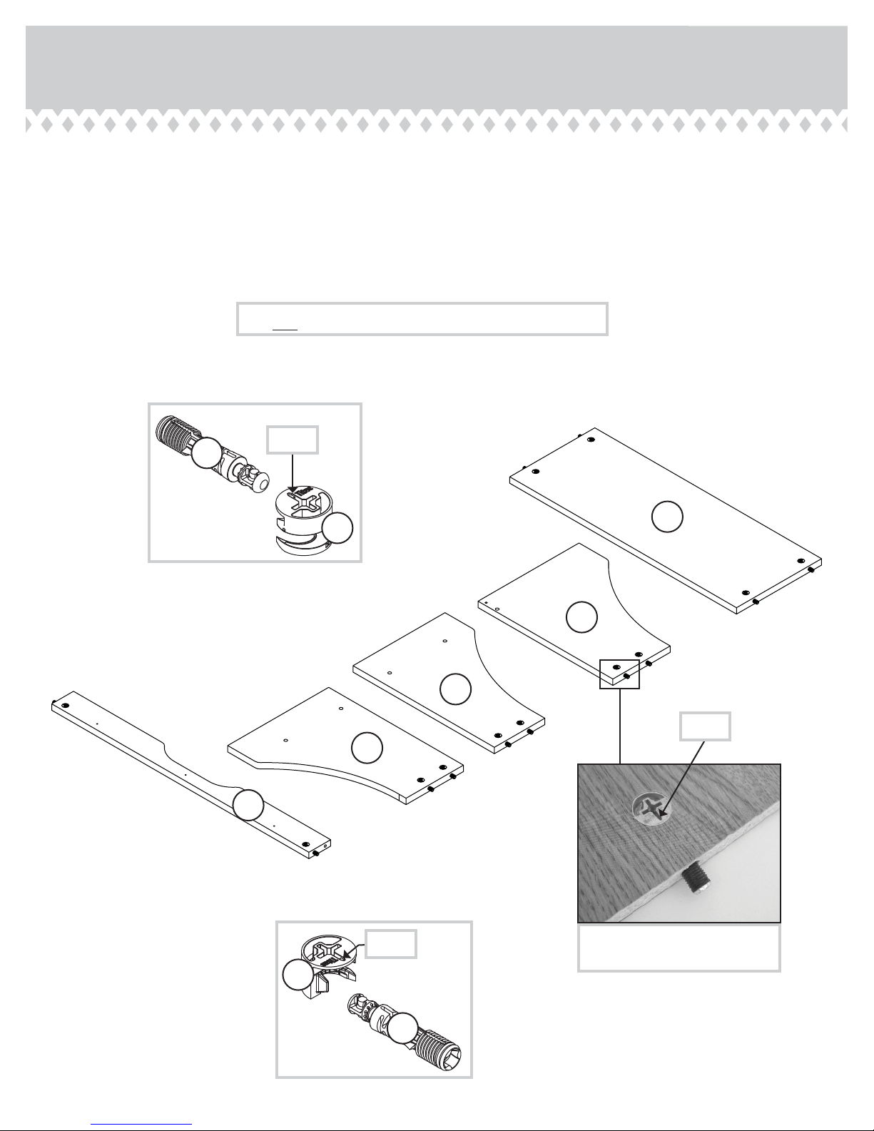
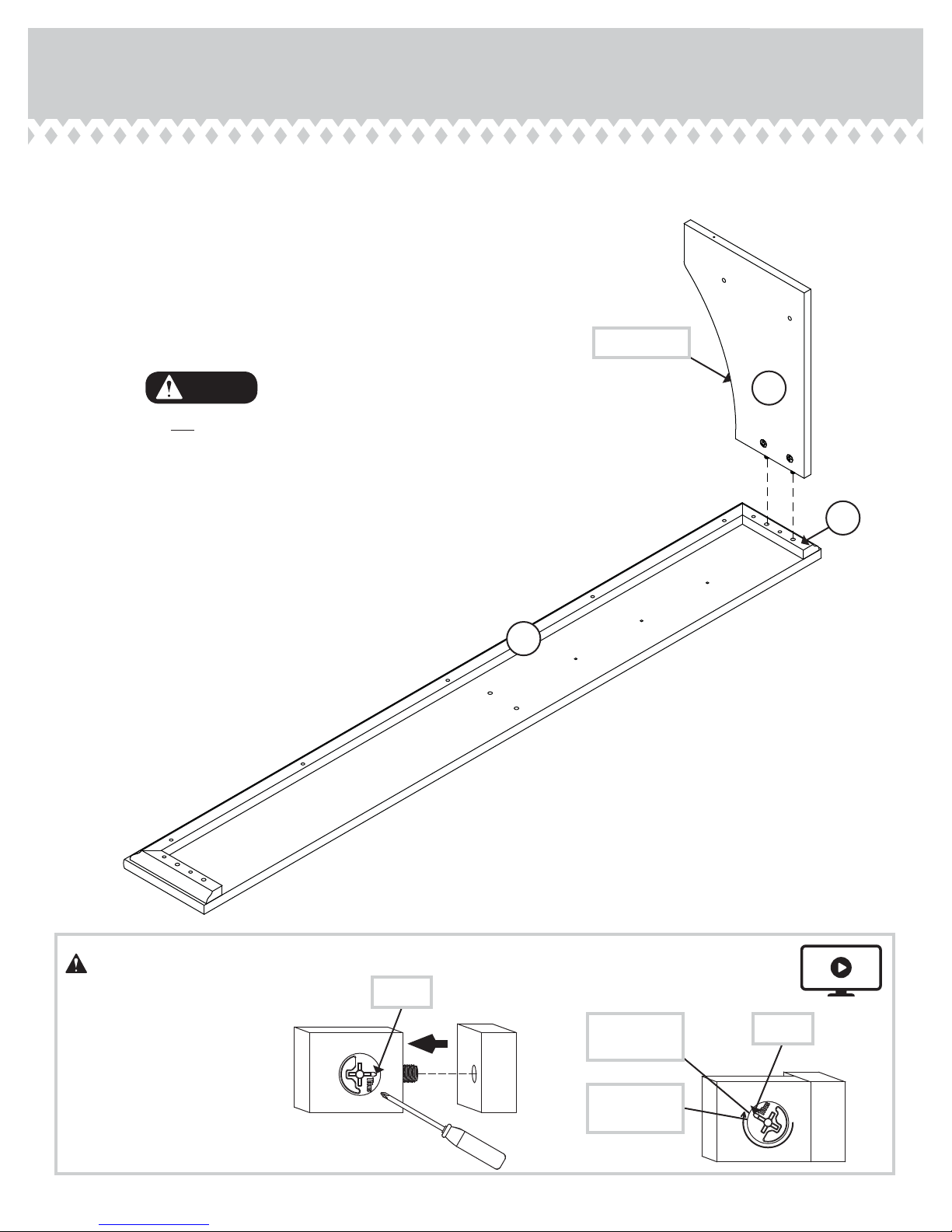
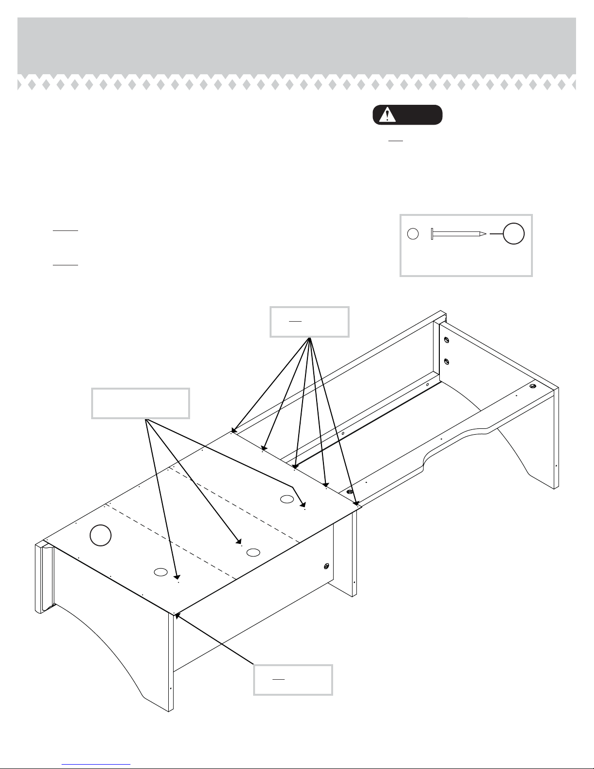
Step 1
Assemble your unit on a carpeted fl oor or on the empty
å
carton to avoid scratching your unit or the fl oor.
Push twelve HIDDEN CAMS (1F) into the ENDS (A and B),
å
UPRIGHT (C), SHELF (E), and SKIRT (I). Then, insert the
metal end of a CAM DOWEL (2F) into each HIDDEN CAM.
Do not tighten the HIDDEN CAMS in this step.
2F
(12 used)
Arrow
1F
E
C
B
Arrow
A
I
1F
Arrow
2F
Insert the metal end of the CAM
DOWEL into the HIDDEN CAM.
P
age 5

Step 2
Tap two MOLDING CONNECTORS (17F) into the notches
å
in the MOLDINGS (J, K, and L).
Use your hammer to tap the MOLDING CONNECTOR (17F) into the notches in the MOLDINGS.
Flat end
17F
Flat end
17F
L
J
K
Page 6

Step 3
Turn the MOLDINGS (J, K, and L) over and fasten them
å
to the TOP (D). Use nine BLACK 1-1/4" FLAT HEAD
SCREWS (7S).
Remember:
Righty tighty.
Lefty loosey.
Finished surface
Finished surface
L
7S
K
BLACK 1-1/4" FLAT HEAD SCREW
(9 used in this step)
J
D
Surface with holes
Rounded edge
P
age 7
Step 4
Fasten the RIGHT END (A) to the RIGHT MOLDING (K).
å
Tighten two HIDDEN CAMS.
Surface with
HIDDEN CAMS
Curved edge
Caution
Do not stand the unit upright without the
BACK fastened. The unit may collapse.
A
K
J
Caution
Risk of damage or
injury. HIDDEN CAMS
must be completely
tightened. HIDDEN
CAMS that are not
completely tightened
may loosen, and parts
may separate. To
completely tighten:
Page 8
Start Tighten
Arrow
Maximum
210 degrees
Minimum
190 degrees
Arrow

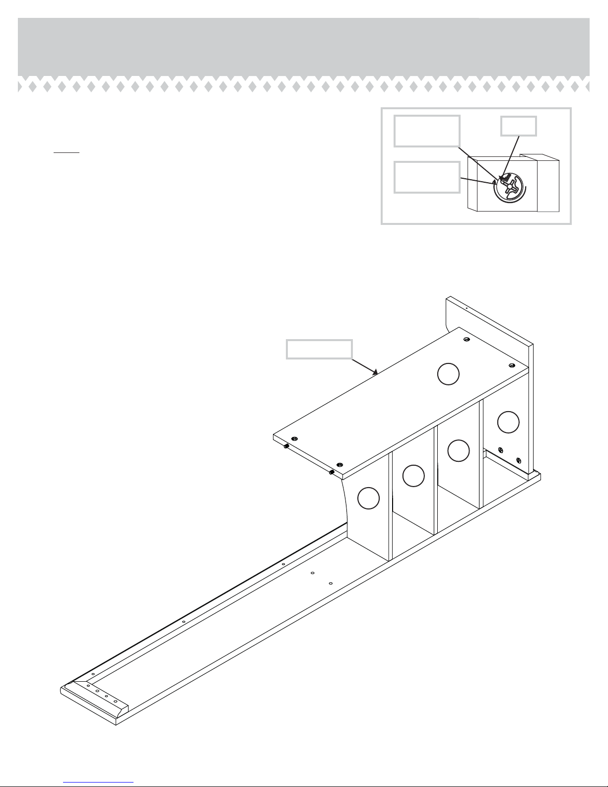
Step 5
Insert three METAL PINS (1R) into the holes shown in the
å
TOP (D).
Slide the DIVIDERS (H) onto the METAL PINS (1R) in the
å
TOP (D).
Now, insert six METAL PINS (1R) into the other end of the
å
DIVIDERS (H).
1R
All curved edges should face
the FRONT MOLDING (J).
D
H
H
H
J
1R
P
age 9
Step 6
Fasten the SHELF (E) to the RIGHT END (A). Tighten two
å
HIDDEN CAMS.
NOTE: Be sure the METAL PINS in the DIVIDERS (H)
å
insert into the holes in the SHELF.
Maximum
210 degrees
Minimum
190 degrees
Arrow
Finished edge
Surface with
HIDDEN CAMS
H
E
A
H
H
Page 10

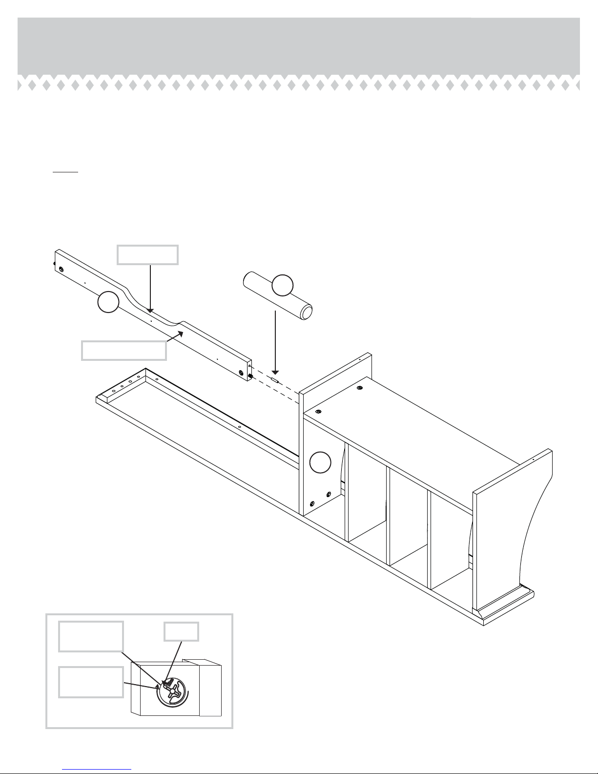
Step 7
Using your short screwdriver, fasten the UPRIGHT (C) to
å
the TOP (D) and SHELF (E). Tighten four HIDDEN CAMS.
Don't worry. It isn't
Rome. This can be built
in a day.
Curved edge
Maximum
210 degrees
D
Surface with
HIDDEN CAMS
Arrow
E
C
Minimum
190 degrees
P
age 11
Step 8
Insert a METAL PIN (1R) into the UPRIGHT (C).
å
Fasten the SKIRT (I) to the UPRIGHT (C). Tighten one
å
HIDDEN CAM.
NOTE: Be sure the METAL PIN in the UPRIGHT inserts
å
into the SKIRT.
Curved edge
I
1R
Surface with holes
Maximum
210 degrees
C
Arrow
Minimum
190 degrees
Page 12
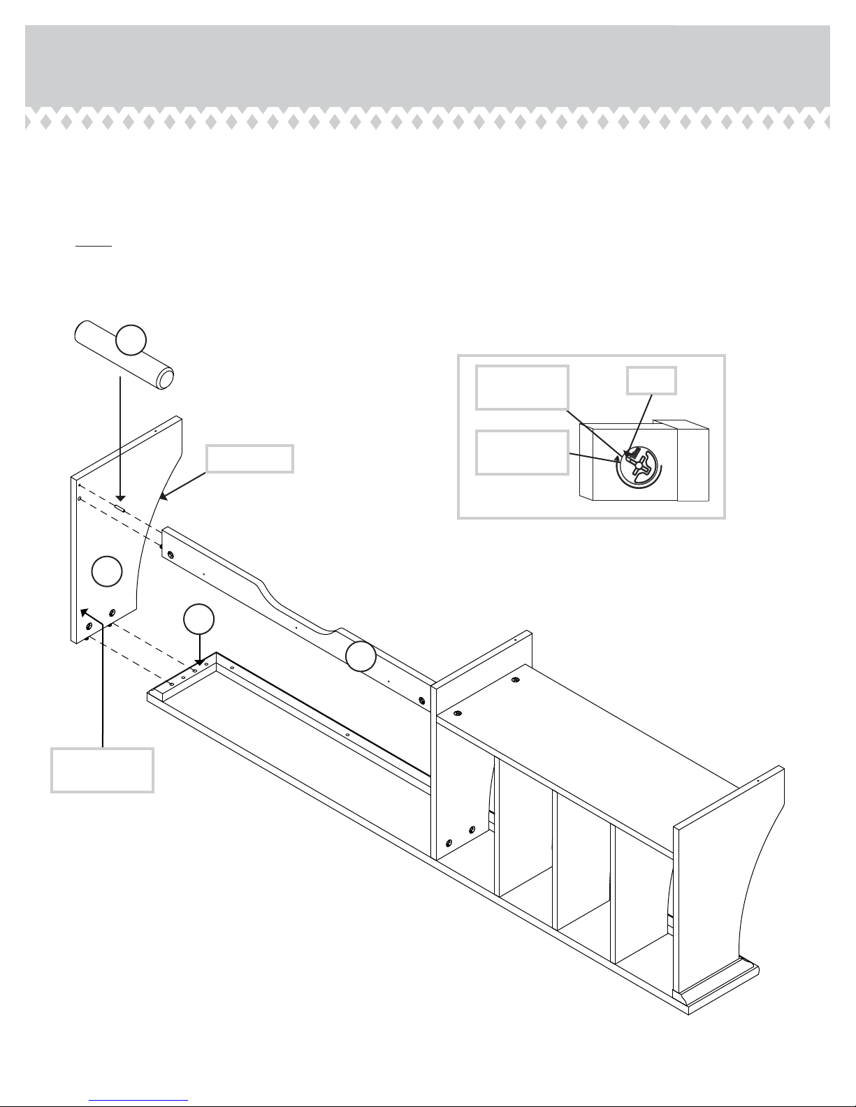
Step 9
Insert a METAL PIN (1R) into the LEFT END (B).
å
Fasten the LEFT END (B) to the LEFT MOLDING (L) and
å
SKIRT (I). Tighten three HIDDEN CAMS.
NOTE: Be sure the METAL PIN in the LEFT END inserts into
å
the SKIRT.
1R
B
Surface with
HIDDEN CAMS
Curved edge
L
Maximum
210 degrees
Minimum
190 degrees
Arrow
I
P
age 13

Step 10
Push a CAM COVER (36P) onto each visible HIDDEN CAM in
å
the ENDS (A and B), UPRIGHT (C), and SHELF (E).
Hey! It's starting to look
like something!
B
E
C
A
36P
Page 14
(10 used)
To cover HIDDEN CAMS
Step 11
Carefully turn your unit over onto its front edges. Unfold the
å
RIGHT BACK (F) and lay it over your unit.
Make equal margins along the top and outer side edge of
å
the RIGHT BACK (F). Push on opposite corners of your unit
if needed to make it “square”.
Fasten the RIGHT BACK (F) to your unit using fourteen
å
NAILS (1N).
NOTE: Be sure to tap NAILS into the holes that line up over
å
the SHELF (E).
NOTE: Perforations have been provided for access through
å
the RIGHT BACK. Carefully cut out the holes needed.
Caution
Do not stand the unit upright without the
BACK fastened. The unit may collapse.
1N
NAIL
(14 used in this step)
Do not tap NAILS
into these holes.
These holes must line
up over the SHELF (E).
F
Do not tap a NAIL
into this hole.
Page 15

Step 12
Unfold the LEFT BACK (G) and lay it over your unit.
å
Make equal margins along the top and outer edge of the
å
LEFT BACK (G). Push on opposite corners of your unit if
needed to make it “square”.
NOTE: The LEFT BACK (G) will overlap the RIGHT BACK (F).
å
Follow the enlarged diagram.
Fasten the LEFT BACK (G) to your unit using three BLACK
å
9/16" LARGE HEAD SCREWS (1S) into the holes shown in
the LEFT BACK. Use fi fteen NAILS (1N) into the top and
both side edges.
1N
NAIL
(15 used in this step)
Caution
Do not stand the unit upright without the
BACK fastened. The unit may collapse.
Notch
Do not tap NAILS into
the bottom row of holes.
G
F
Page 16
1S
BLACK 9/16" LARGE HEAD SCREW
(3 used in this step)
G
F
The LEFT BACK (G) will
overlap the RIGHT BACK (F).
Step 13
Carefully stand your unit upright.
å
The instructions for fastening your unit to the 418294
å
Computer Desk is in the Computer Desk assembly manual.
You will use seven NAILS (1N) and three BLACK 1-7/8" FLAT
HEAD SCREWS (2S) from your Hutch hardware to fasten to the
Computer Desk.
NOTE: Please read the back pages of the instruction booklet for
å
important safety information.
This completes assembly. Clean with your favorite furniture
å
polish or a damp cloth. Wipe dry.
Pro Tip: Lift with your
legs. And, you know,
your arms.
30 lbs.
418294
Computer Desk
20 lbs. total
P
age 17

WARNING
Please use your furniture correctly and safely. Improper use can cause safety hazards,
or damage to your furniture or household items. Carefully read the following chart.
Look out for: What can happen: How to avoid the problem:
• Overloaded shelves and drawers.
• Improper loading can cause the product
to be top-heavy.
• Risk of injury.
• Top-heavy furniture can tip over.
• Overloaded shelves and drawers can
break.
• Never exceed the weight limits shown in
the instructions.
• Work from bottom to top when loading
shelves and drawers. Place the heavier
items on the lower shelves or in lower
drawers.
• Improperly moving furniture that is not
designed and equipped with casters.
• Placing TVs on furniture items that are
not designed to support a television is
hazardous.
• Furniture can tip over or break if
improperly moved.
• Physical injury. Furniture can be very
heavy.
• Breakage of tops - particularly with
double pedestal furniture (drawers at both
ends).
• Risk of injury or death. TVs can be very
heavy. Plus the weight and location of the
picture tube tends to make TVs unbalanced
and prone to tipping forward.
• Unload shelves and drawers from top to
bottom before moving the unit.
• Do not push furniture, especially on a
carpeted fl oor. Have a friend help you lift
the item and set it in place.
• Provide support to the center section of
the top when lifting the furniture.
• This product is not designed to support a
television.
Page 18
 Loading...