

www.teknikoffice.co.uk
Teknik
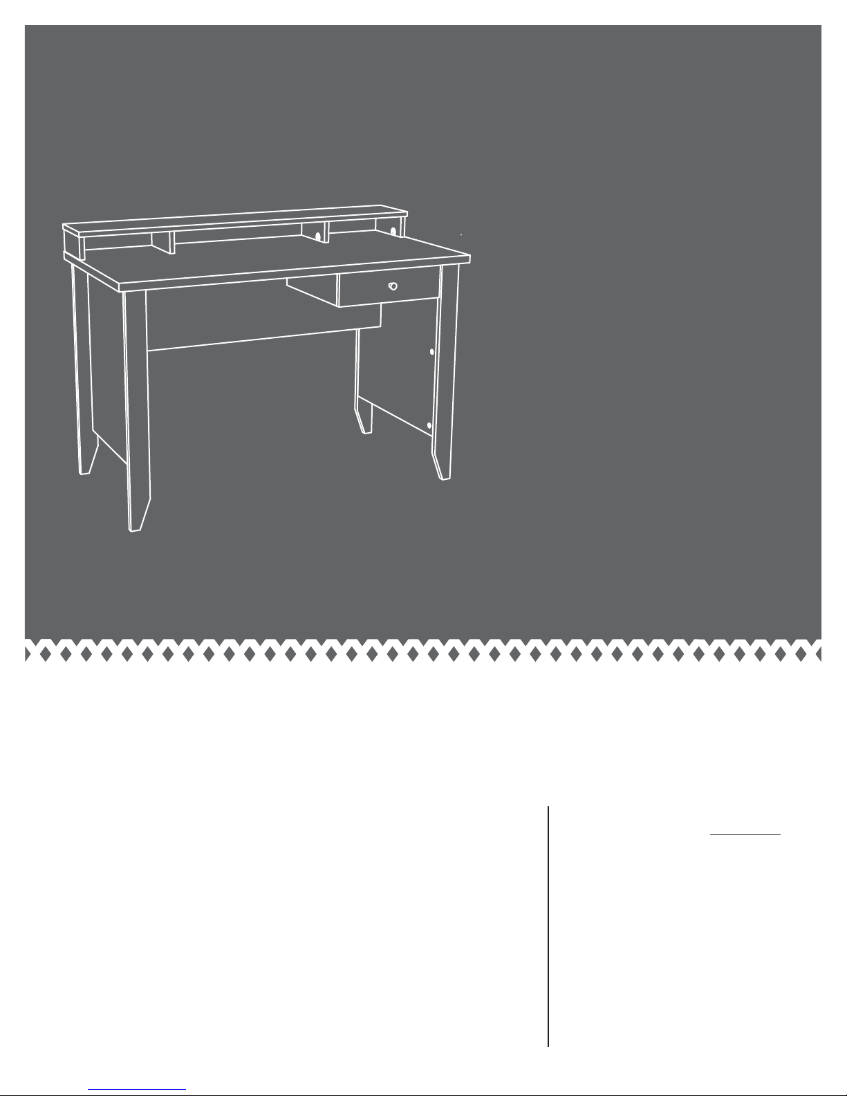
The original desktop.
Writing Desk
5418269
NOTE: THIS INSTRUCTION
BOOKLET CONTAINS IMPORTANT
SAFETY INFORMATION.
PLEASE READ AND KEEP FOR
FUTURE REFERENCE.
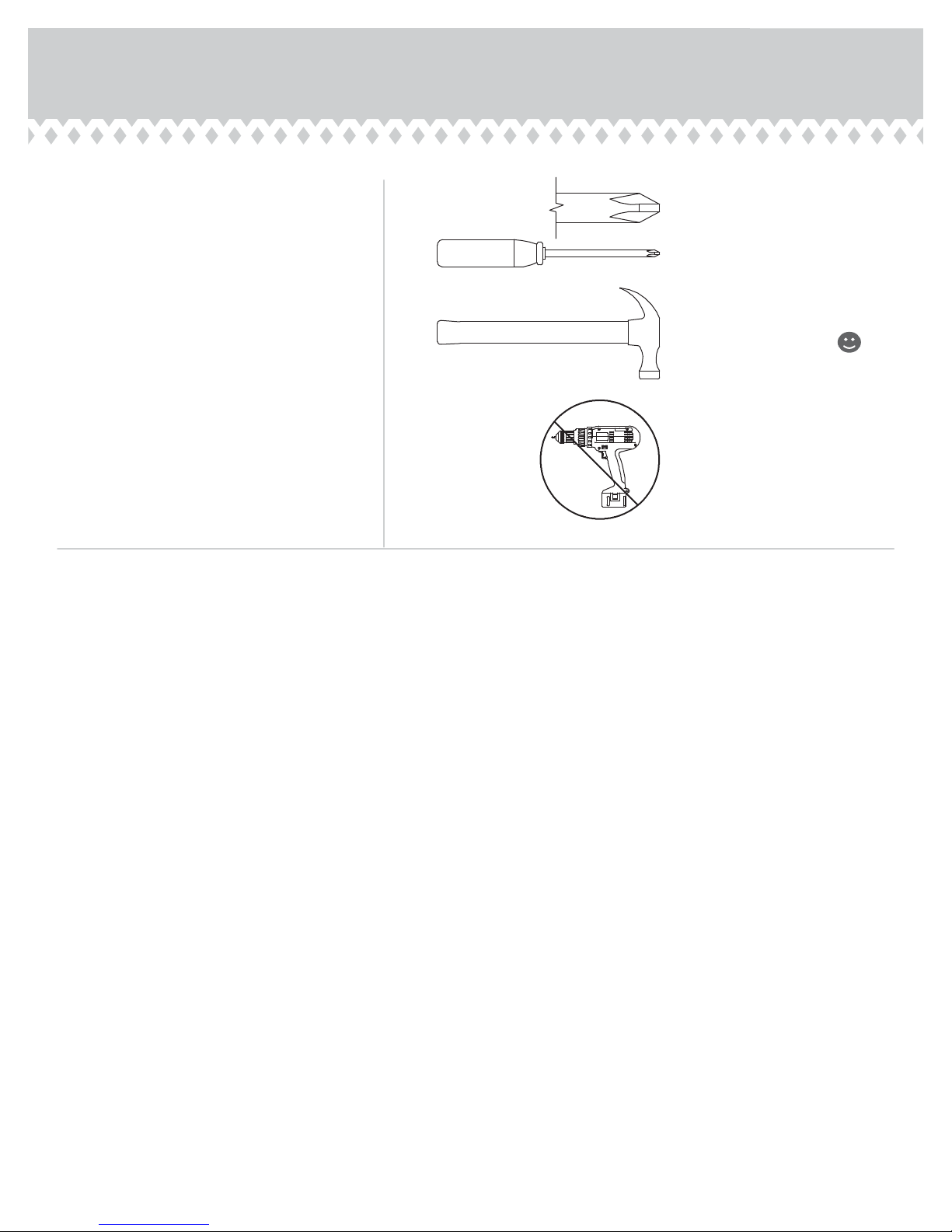
Table of Contents Assembly Tools Required
Part Identifi cation
Hardware Identifi cation
Assembly Steps
Français
Español
Safety
Warranty
5-18
19-21
22-24
25-26
27
3
No. 2 Phillips Screwdriver
4
Tip Shown Actual Size
Hammer
Not actual size
Skip the power trip.
This time.
Page 2
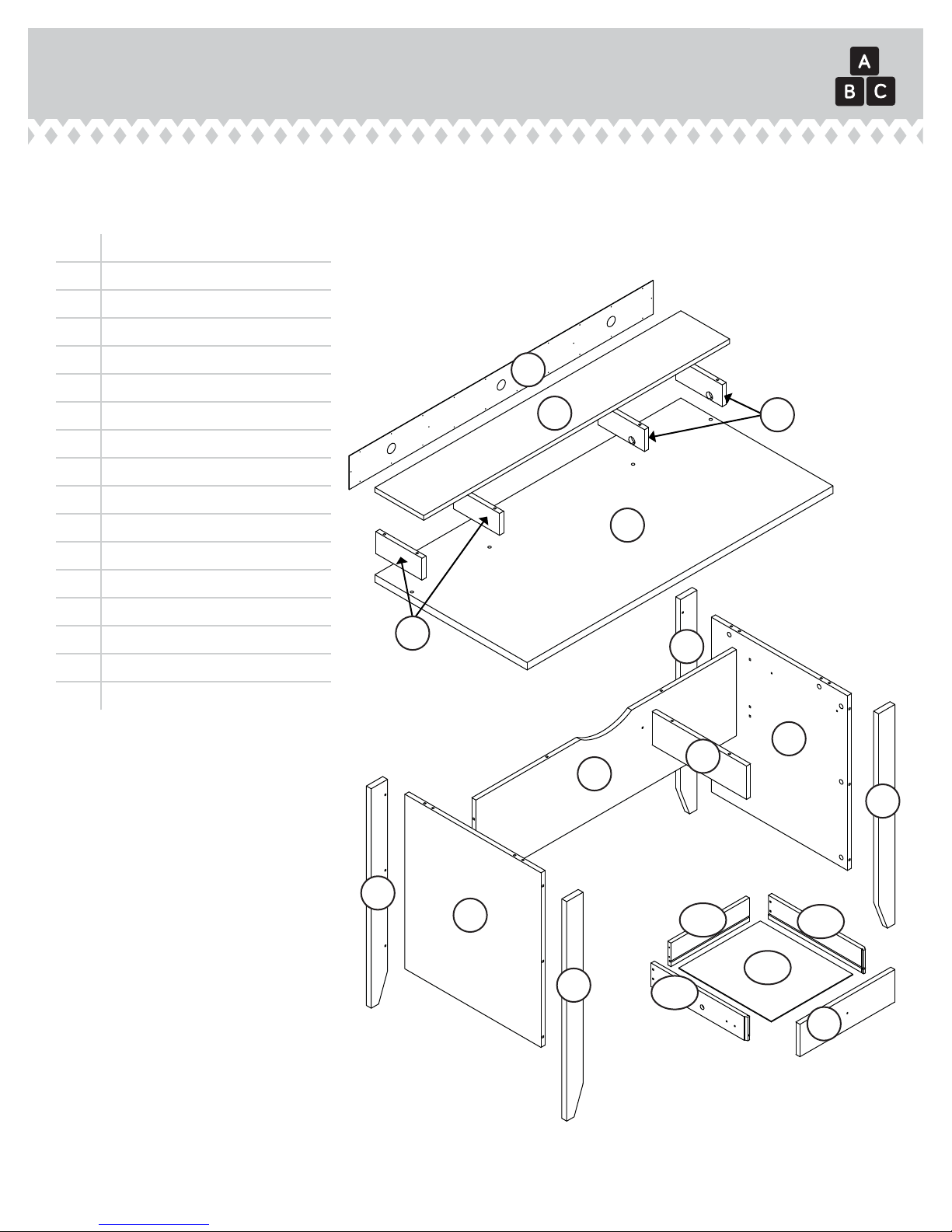
Part Identifi cation
å While not all parts are labeled, some of the parts will have a label or an inked letter on the edge
to help distinguish similar parts from each other. Use this part identifi cation to help identify similar parts.
A RIGHT END (1)
B LEFT END (1)
C HUTCH RIGHT END (2)
D UPRIGHT (1)
Now you know
our ABCs.
E TOP (1)
F HUTCH TOP (1)
G MODESTY PANEL (1)
H BACK (1)
I RIGHT FRONT LEG (1)
J LEFT FRONT LEG (1)
K REAR LEG (2)
L DRAWER FRONT (1)
M HUTCH LEFT END (2)
D20 DRAWER RIGHT SIDE (1)
D21 DRAWER LEFT SIDE (1)
D74 DRAWER BACK (1)
D716 DRAWER BOTTOM (1)
M
H
F
C
E
K
A
D
G
I
K
B
J
D21
D74
D20
D716
L
P
age 3
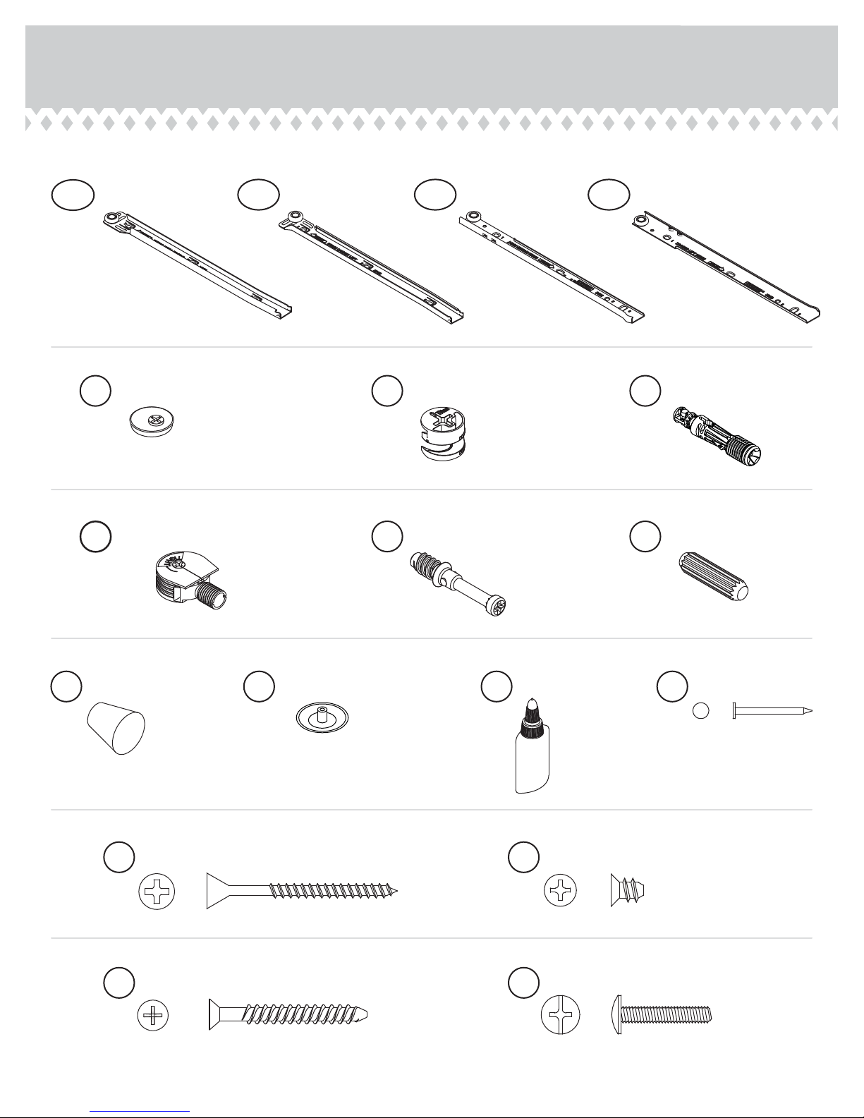
Hardware Identifi cation
å Screws are shown actual size. You may receive extra hardware with your unit.
35GA
CABINET RIGHT - 1
10A
SLIDE CAM - 2
7F
TWIST-LOCK® FASTENER - 4
35GB
CABINET LEFT - 1
35GC
1F
HIDDEN CAM - 20
8F
CAM SCREW - 6
DRAWER RIGHT - 1
35GD
DRAWER LEFT - 1
2F
CAM DOWEL - 14
15F
WOOD DOWEL - 12
25K
KNOB - 1
2S
BLACK 1-7/8" FLAT HEAD SCREW - 7
30S
BLACK 1-9/16" FLAT HEAD SCREW - 4
Page 4
12P
CAM COVER - 6
54M
GLUE - 1
3S
GOLD 5/16" FLAT HEAD SCREW - 8
37S
BLACK 7/8" MACHINE SCREW - 1
1N
NAIL - 24
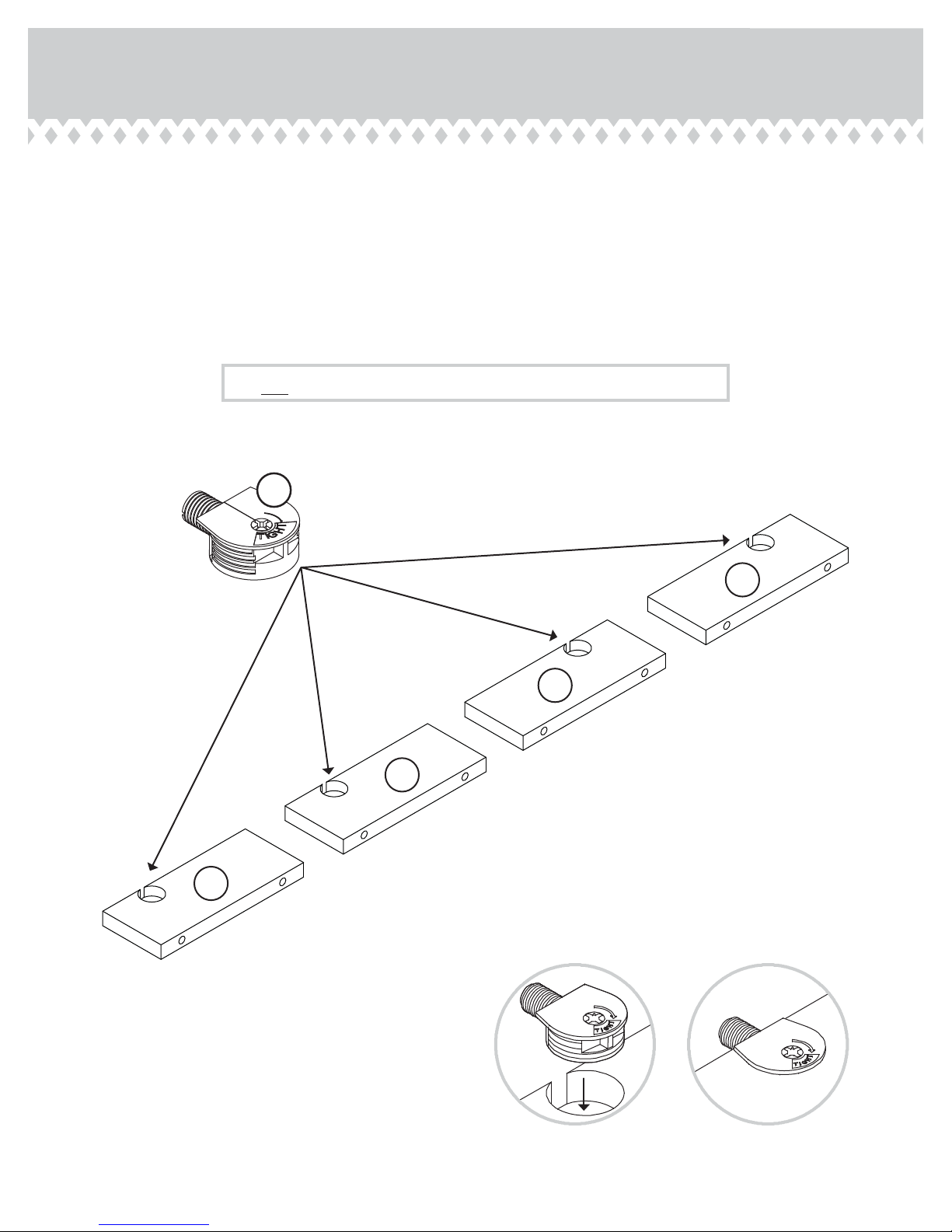
Step 1
Assemble your unit on a carpeted fl oor or on the empty
å
carton to avoid scratching your unit or the fl oor.
To begin assembly, push a SAUDER TWIST-LOCK®
å
FASTENER (7F) into the large holes in the
HUTCH ENDS (C and M).
Do not tighten the TWIST-LOCK® FASTENERS in this step.
7F
M
M
C
C
P
age 5
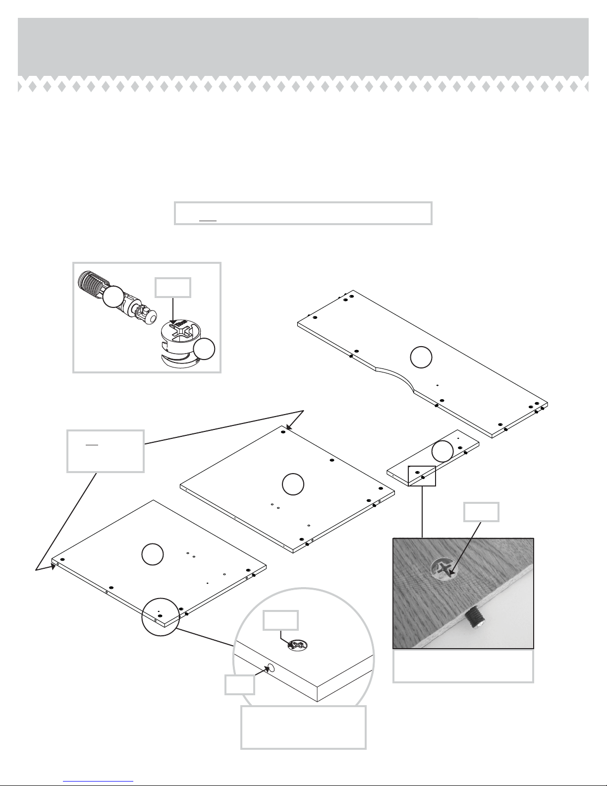
Step 2
Push twenty HIDDEN CAMS (1F) into the ENDS (A and B),
å
UPRIGHT (D), and MODESTY PANEL (G). Then, insert the metal
end of a CAM DOWEL (2F) into each HIDDEN CAM, except the
long edges of the ENDS (A and B).
Do not tighten the HIDDEN CAMS in this step.
2F
(14 used)
(20 used)
Do not insert
CAM DOWELS
into these edges.
Arrow
1F
G
D
B
Arrow
A
Page 6
Arrow
Insert the metal end of the CAM
DOWEL into the HIDDEN CAM.
Hole
The arrow in the HIDDEN
CAM must point toward the
hole in the edge of the board.

Step 3
Turn six CAM SCREWS (8F) into the FRONT LEGS (I and J).
å
Fasten the ENDS (A and B) to the FRONT LEGS (I and J).
å
Tighten six HIDDEN CAMS.
(6 used)
8F
I
These surfaces
should be even.
J
Angled edge
Surface with
HIDDEN CAMS
B
These surfaces
should be even.
J
Angled edge
I
Surface with
HIDDEN CAMS
A
Edge with HIDDEN CAMS
1
2
P
age 7

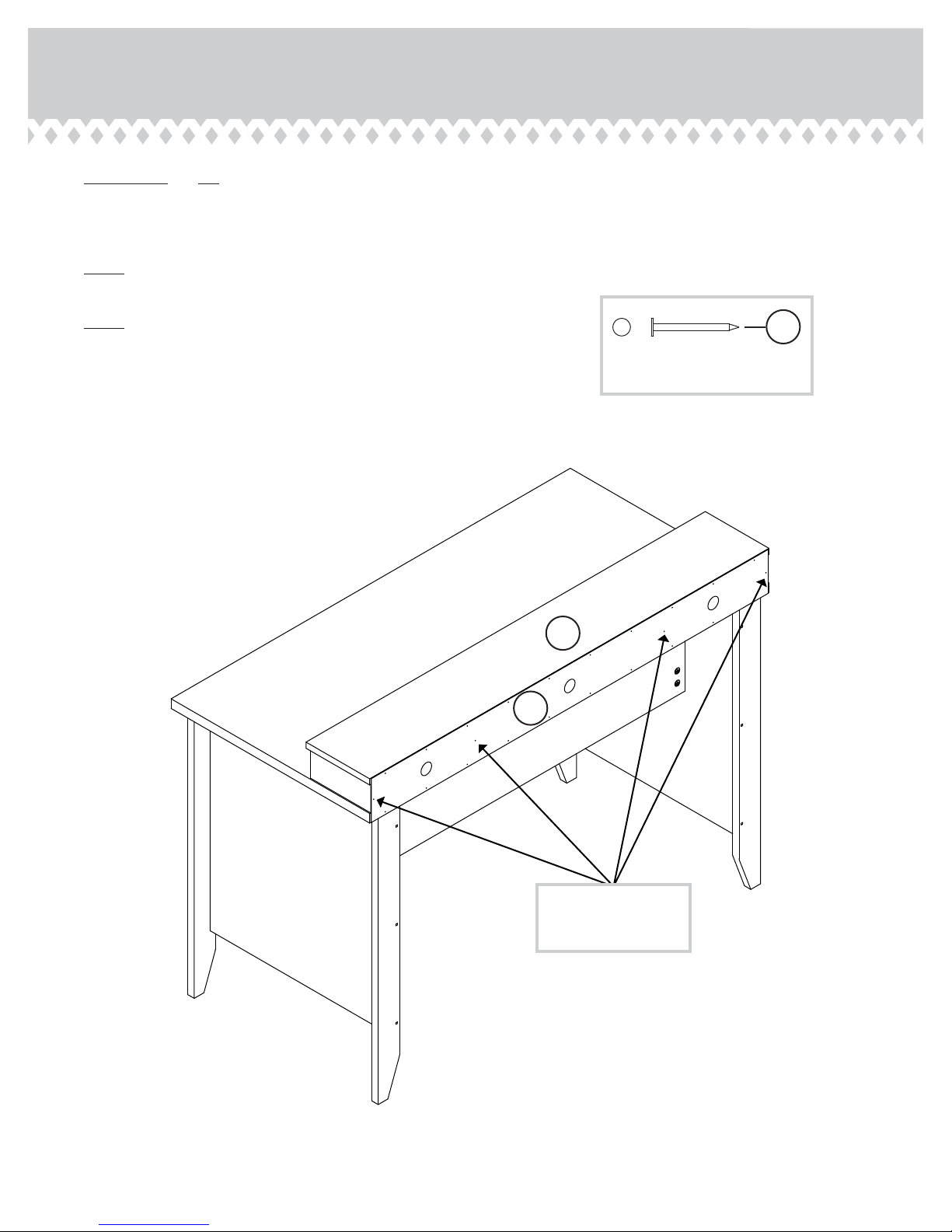
Step 4
Fasten the REAR LEGS (K) to the ENDS (A and B). Use six
å
BLACK 1-7/8" FLAT HEAD SCREWS (2S).
Angled edge
Some assembly
(and snacks) required.
Surface with
HIDDEN CAMS
Surface with
HIDDEN CAMS
K
K
A
BLACK 1-7/8" FLAT HEAD SCREW
B
2S
(6 used in this step)
Page 8

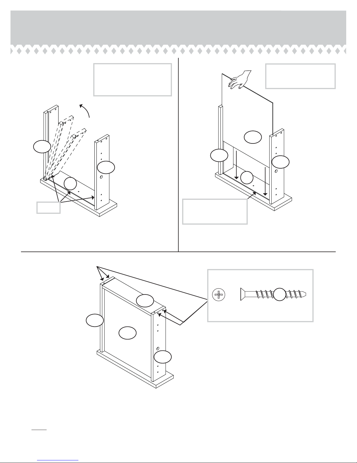
Step 5
Fasten the CABINET RIGHT (35GA) to the RIGHT END (A)
å
and the CABINET LEFT (35GB) to the UPRIGHT (D). Use
four GOLD 5/16" FLAT HEAD SCREWS (3S) through
holes #1 and #3.
3S
GOLD 5/16" FLAT HEAD SCREW
(4 used in this step)
Roller end
2
1
3
D
Roller end
1
2
3
I
A
Surface with
HIDDEN CAMS
Edge and surface
with HIDDEN CAMS
P
age 9

Step 6
Fasten the MODESTY PANEL (G) to the ENDS (A and B).
å
Tighten six HIDDEN CAMS.
Surface with
HIDDEN CAMS
A
Caution
Risk of damage or
injury. HIDDEN CAMS
must be completely
tightened. HIDDEN
CAMS that are not
completely tightened
may loosen, and parts
may separate. To
completely tighten:
Surface without
HIDDEN CAMS
B
Surface with
HIDDEN CAMS
G
Notch
Start Tighten
Arrow
Maximum
210 degrees
Minimum
190 degrees
Arrow
Page 10

Step 7
First, fi ll four holes in the TOP (E) 1/4 to 1/2 full with GLUE (54M).
å
Then, insert four WOOD DOWELS (15F) into the holes. Wipe away
the excess GLUE.
Next, place drops of GLUE (54M) onto the WOOD DOWELS (15F)
å
in the TOP (E).
Finally, fasten the TOP (E) to the ENDS (A and B) and MODESTY
å
PANEL (G). Tighten six HIDDEN CAMS.
NOTE: Be sure the WOOD DOWELS in the TOP insert into the
å
holes in the ENDS. Wipe away the excess GLUE.
Fill the holes 1/4 to 1/2 full with GLUE.
Caution
!
Inspect the parts thoroughly before
assembling. Disassembly of glued
parts is extremely di cult.
15F
54M
Place GLUE in the
exact holes shown.
A
with holes
Surface
G
B
E
15F
Finished edge
54M
P
age 11

Step 8
Fasten the UPRPIGHT (D) to the TOP (E). Tighten two
å
HIDDEN CAMS.
Fasten the UPRIGHT (D) to the MODESTY PANEL (G). Use
å
one BLACK 1-7/8" FLAT HEAD SCREW (2S).
Maximum
210 degrees
Minimum
190 degrees
2S
Arrow
Surface without
HIDDEN CAMS
D
E
BLACK 1-7/8" FLAT HEAD SCREW
(1 used in this step)
G
Page 12

Step 9
Carefully stand your unit upright.
å
Fasten the HUTCH UPRIGHTS (C and M) to the TOP (E).
å
Tighten four TWIST-LOCK® FASTENERS.
Fill the holes in the edges of the HUTCH UPRIGHTS (C
å
and M) 1/4 to 1/2 full with GLUE (54M). Then, insert eight
WOOD DOWELS (15F) into the holes. Wipe away the
excess GLUE.
Place drops of GLUE (54M) onto the WOOD
å
DOWELS (15F) in the HUTCH UPRIGHTS (C and M).
Press the HUTCH TOP (F) onto the WOOD DOWELS in
å
the HUTCH UPRIGHTS. Wipe away the excess GLUE.
(8 used)
F
Surface without holes
15F
M
How to use the SAUDER TWIST-LOCK® FASTENER
1. Insert the dowel end of the FASTENER into the hole of the
adjoining part.
NOTE: The dowel end of the FASTENER must remain fully
inserted in the hole of the adjoining part while locking
the FASTENER.
2. Tighten the FASTENER with a Phillips screwdriver as tight
as possible.
Dowel end
Unfi nished edge
Surface with
TWIST-LOCK®
FAST EN ER
M
C
E
C
Surface without
TWIST-LOCK®
FAST EN ER
Caution
!
Inspect the parts thoroughly before
assembling. Disassembly of glued
parts is extremely di cult.
54M
Fill the holes 1/4 to 1/2 full with GLUE.
P
age 13
Step 10
IMPORTANT: Do not pick up or move your unit by using
å
the TOP (F).
Fasten the BACK (H) to your unit using the NAILS (1N).
å
NOTE: Be sure to tap NAILS into the holes that line up
å
over the HUTCH UPRIGHTS (C and M).
NOTE: Perforations have been provided for access
å
through the BACK. Carefully cut out the holes needed.
1N
NAIL
(24 used in this step)
F
Unfi nished
surface
H
Page 14
These holes must line
up over the HUTCH
UPRIGHTS (C and M).
Step 11
12
D20
The tabs should insert freely
into the slots. Gently tilt the
DRAWER SIDES side to side
until the tabs slip into the slots.
D21
With the palm of your hand,
tap the DRAWER BOTTOM
down into the groove.
Unfi nished
surface
D716
D20
D21
L
L
Groove
Insert the DRAWER SIDES (D20 and D21) at an angle
å
into the slot at each end of the DRAWER FRONT (L).
Be sure the DRAWER
BOTTOM inserts into the
DRAWER FRONT groove.
Slide the DRAWER BOTTOM (D716) into the grooves in the
å
DRAWER SIDES (D20 and D21) and DRAWER FRONT (L).
3
D74
D20
D716
D21
Fasten the DRAWER BACK (D74) to the DRAWER SIDES (D20
å
and D21). Use four BLACK 1-9/16" FLAT HEAD SCREWS (30S).
NOTE: Be sure the DRAWER BOTTOM (D716) inserts into the
å
groove of the DRAWER BACK (D74).
Start each screw a few turns before
completely tightening any of them.
30S
BLACK 1-9/16" FLAT HEAD SCREW
(4 used in this step)
P
age 15

Step 12
Insert a SLIDE CAM (10A) into the DRAWER SIDES (D20 and D21).
å
Fasten the DRAWER RIGHT (35GC) to the DRAWER RIGHT SIDE (D20)
å
and the DRAWER LEFT (35GD) to the DRAWER LEFT SIDE (D21). Use
four GOLD 5/16" FLAT HEAD SCREWS (3S) through holes #1 and #3.
NOTE: The screw head in the CAM must be visible through the slotted
å
hole in the SLIDE.
Fasten the KNOB (25K) to the DRAWER FRONT (L). Use a BLACK 7/8"
å
MACHINE SCREW (37S).
Roller end
10A
1
2
3
D21
Screw head - turn CAM to line up holes in
the SLIDES with holes in DRAWER SIDES
10A
Roller end
D20
L
1
25K
37S
2
3
BLACK 7/8" MACHINE SCREW
(1 used for the KNOB)
Page 16
3S
GOLD 5/16" FLAT HEAD SCREW
(4 used in this step)

Step 13
To insert the drawer into your unit, tip the front of the
å
drawer down and drop the rollers on the drawer behind the
rollers on the unit. Lift the front of the drawer up and slide
it into the unit.
Push a CAM COVER (12P) onto each visible HIDDEN CAM.
å
20 lbs.
12P
50 lbs.
10 lbs.
Place the roller on the SLIDE
behind the roller on the RAIL.
(6 used)
To cover HIDDEN CAMS
P
age 17

Step 14
To make adjustments to the drawers, loosen SCREW #3 in the SLIDES a 1/4 turn, then turn the CAM
å
clockwise or counter-clockwise. Notice how the drawer raises or lowers as you turn the CAM. The
higher the screw in the oblong hole, the higher your drawer front will be. The lower the screw, the
lower the drawer front. By adjusting the drawers this way, it will help the DRAWER FRONTS line up
better when closed. Tighten the SCREW when fi nished with adjustments.
NOTE: Please read the back pages of the instruction booklet for important safety information.
å
This completes assembly. Clean with your favorite furniture polish or a damp cloth. Wipe dry.
å
Loosen screw #3 a 1/4 turn, turn the cam a 1/4 turn
maximum in both the clockwise and counter-clockwise
directions to make adjustments, and then tighten screw #3.
The higher the screw in the oblong hole, the
higher your drawer front will be. The lower the
screw, the lower the drawer front.
Cam
Page 18

WARNING
Please use your furniture correctly and safely. Improper use can cause safety hazards,
or damage to your furniture or household items. Carefully read the following chart.
Look out for: What can happen: How to avoid the problem:
• Overloaded shelves and drawers.
• Improper loading can cause the product
to be top-heavy.
• Risk of injury.
• Top-heavy furniture can tip over.
• Overloaded shelves and drawers can
break.
• Never exceed the weight limits shown in
the instructions.
• Work from bottom to top when loading
shelves and drawers. Place the heavier
items on the lower shelves or in lower
drawers.
• Improperly moving furniture that is not
designed and equipped with casters.
• Placing TVs on furniture items that are
not designed to support a television is
hazardous.
• Furniture can tip over or break if
improperly moved.
• Physical injury. Furniture can be very
heavy.
• Breakage of tops - particularly with
double pedestal furniture (drawers at both
ends).
• Risk of injury or death. TVs can be very
heavy. Plus the weight and location of the
picture tube tends to make TVs unbalanced
and prone to tipping forward.
• Unload shelves and drawers from top to
bottom before moving the unit.
• Do not push furniture, especially on a
carpeted fl oor. Have a friend help you lift
the item and set it in place.
• Provide support to the center section of
the top when lifting the furniture.
• This product is not designed to support a
television.
 Loading...