

Smart DC Power Supplies
Amazon IPC-3 and IPC-5
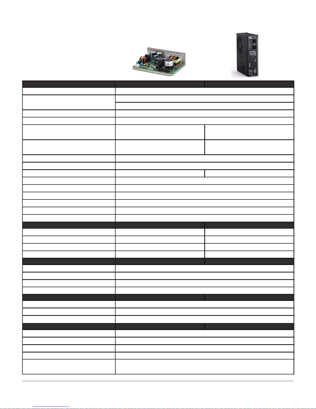
75 Volt Intelligent Power Center
Amazon IPC-3 and IPC-5 power supplies deliver stiff, responsive
75 VDC power to Eclipse, Meridian, and ClearPath servo systems.
These DSP-based supplies feature tight power regulation and high
peak output to support high performance motion control. And, with
a small footprint and attractive pricing, the IPC saves on space,
weight, and machine cost as well.
IPC-3 / IPC-5 Features
75 VDC output with tight regulation, even with large peak
loads.
Dual AC input voltage ranges: 95-125VAC; 190-250VAC.
High peak output relative to continuous rating (2.5x),
optimized for servo drive peak demand requirements.
Rapid output bus discharge upon AC power removal.
Built-in, automatic regenerated power management.
Large output capacitance for reduced ripple and
increased efficiency.
Fan mounting holes provided for increased continuous
power (IPC-5 only).
IPC-5 is fully enclosed; IPC-3 is open frame.
Three year warranty.
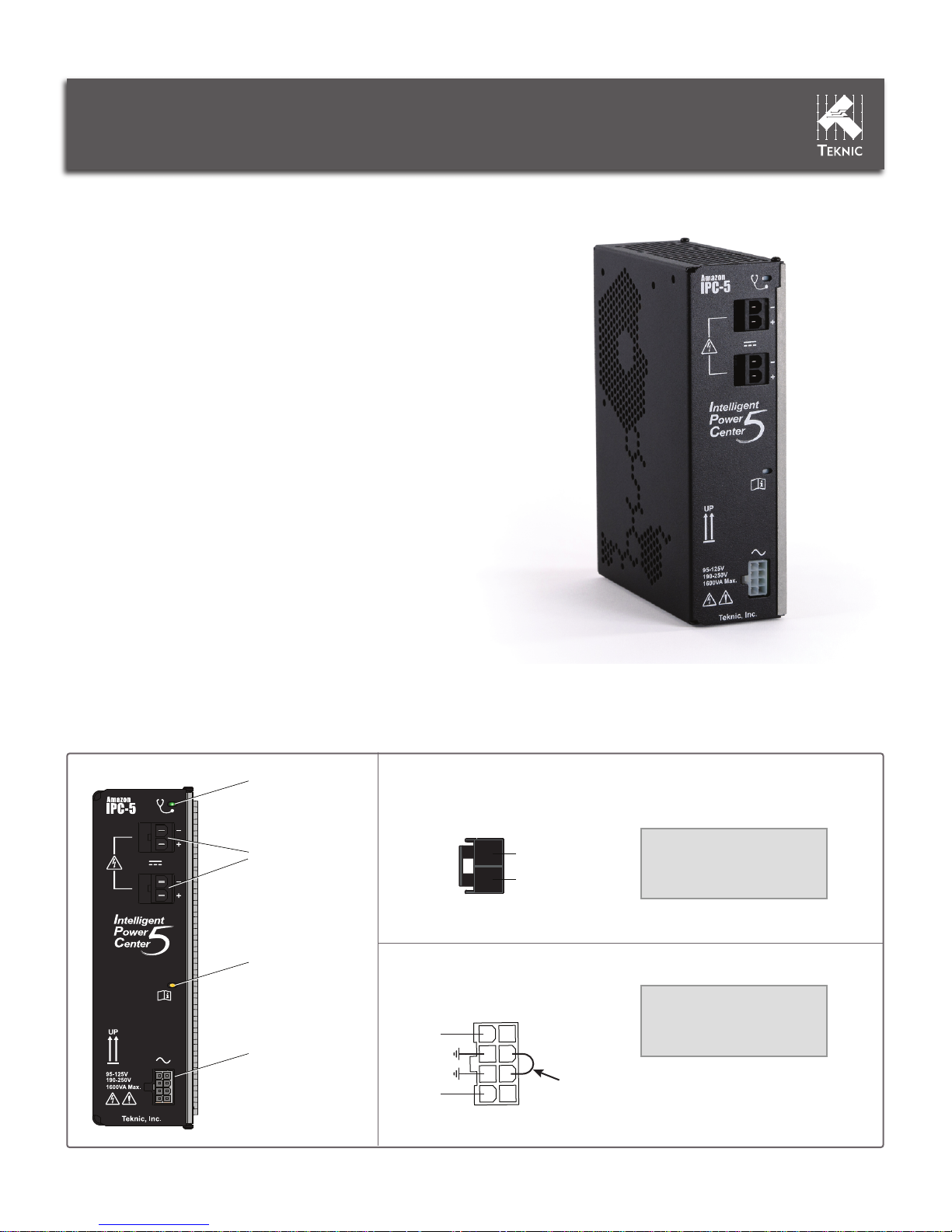
Amazon IPC-5 Power Supply
Front Panel Mating Components
Regen Indicator
See LED blink code
reference later in this
document for details.
DC Output
Connectors
Outputs 75VDC to your
servo drive, step drive,
or ClearPath motor.
Information LED
See LED blink code
reference later in this
document for details.
AC Input
Connector
Accepts standard 115 VAC
and 230 VAC (nominal)
voltage ranges.
Note: No user serviceable parts inside
AC Line
PE GND
(pins 6 or 7)
AC Line
DC Output
Mating Connector
2
1
WIRE ENTRY VIEW
AC Input
Mating Connector
5 1
6 2
7 3
8 4
WIRE ENTRY VIEW
DC Bus (V-)
DC Bus (V+)
Install 18 AWG jumper
when wiring to 95-125VAC
Omit jumper
when wiring to 190-250 VAC
Mating Components List
Housing: Molex/44441-2002
Terminals: Molex/43375-0001
Crimp Tool: Molex/63811-7200
Cable:
14-16AWG, 600V, stranded
Mating Components List
Housing: Molex/39-01-2080
Terminals: Molex/39-00-0039
Crimp Tool: Molex/638190900
Cable:
18AWG, 300V, stranded

Safety and Use Instructions
1.
Read these instructions.
2.
Keep these instructions.
3.
Heed all warnings.
4.
Do not use this apparatus near water.
5.
Clean only with a dry cloth.
6.
Do not block any ventilation openings. Install in accordance
with manufacturer’s instructions.
7.
Do not install near any heat sources.
8.
Protect the power cord and plug from being walked on or
pinched particularly at plugs, convenience receptacles, and
the point where it exits from the apparatus.
9.
Only use attachments and accessories specified by Teknic.
10.
Refer all servicing to qualified service personnel.
11.
The plug on the power cord is the AC mains disconnect
device and must remain readily operable. To completely
disconnect this apparatus from the AC mains, disconnect the
power supply cord plug from the AC receptacle.
12.
This apparatus shall be connected to a mains socket outlet
with a protective earthing connection. Equipment may be
located above or below this apparatus, but some equipment
may generate too much heat and degrade the performance of
this apparatus.
13.
To reduce the risk of fire or electric shock, do not expose this
apparatus to rain or moisture. Apparatus shall not be exposed
to dripping or splashing and no objects filled with liquids, shall
be placed on the apparatus.
IMPORTANT: Read this section before attempting to install, apply
power to, or operate an IPC power supply. Failure to understand
and follow the safety and use information presented in this
document could result in property damage, bodily injury or death.
Precautionary Statement
Always follow appropriate safety precautions when installing and
using a power supply. Equipment should be designed and utilized
to prevent personnel from coming into contact with moving parts
and electrical contacts that could potentially cause injury or death.
Read all cautions, warnings and notes before attempting to
operate or service power supplies and motion control devices.
Follow all applicable codes and standards when using this
equipment. Failure to apply this equipment as described may
impair or neutralize protections built into the product.
General Disclaimer
The User is responsible for determining the suitability of products
for their different applications. The User must ensure that Teknic’s
products are installed and utilized in accordance with all local,
state, federal and private governing bodies and meet all applicable
health and safety standards.
Teknic has made all reasonable efforts to accurately present the
information in the published documentation and shall not be
responsible for any incorrect information which may result from
unintentional oversights. Due to continuous product improvements,
the product specifications as stated in the documentation are
subject to change at any time and without notice. The User is
responsible for consulting a representative of Teknic for detailed
information and to determine any changes of information in the
published documentation.
General Safety Instructions (all models)
Should Teknic’s products be used in an application that is safety
critical, the User must provide appropriate safety testing of the
products, adequate safety devices, guarding, warning notices and
machine-specific training to protect the operator from injury.
IPC-3 Special Safety Note
The IPC-3 is an open frame power supply with user-accessible,
hazardous voltages present. Improper handling of this device
while powered by AC mains may result in electrical shock, burns,
or death.
Users of this device, and any equipment or system that incorporates this device, must be protected from exposure to electrical
shock through the installation of appropriate shields, access
guards, interlocks, warning signs and user manuals that include
safe handling practices for open frame power supplies.
IPC Use Instructions
To connect your IPC power supply to a load:
• Disconnect IPC from AC mains power.
• Connect DC power cable from IPC to the load.
• Apply AC power to IPC.
To disconnect your IPC Power Supply from a load
• Turn off (unplug) IPC.
• Disconnect DC power cable from the load.
Additional Use Notes
• Do not wire multiple IPCs together; they are not designed
to operate in series or in parallel configurations.
• Always use recommended wire gauge (or larger) for all
cables connected to an IPC power supply.
• Understand and follow all safety markings and warnings
printed on the IPC and described within this document.
IPC-3 Power Supply
2
LED Codes
Regen Indicator
(Green LED)
IPC State Description
Rapid Blink
(
16 blinks/second)
On (normal)
No action required.
The power supply is working properly. No
significant regen detected.
LED intermittently turns
on solid but returns to
rapid blink.
Regenerated energy
was detected.
No action required.
The power supply is working properly. LED
turns on solid when DC bus voltage rises above nominal while
staying below the Regen Control Threshold.
Blink
(3 blinks/second)
Regen control circuit
was activated.
No action required.
The power supply is working properly. This
latching signal indicates that the bus voltage has gone over the
Regen Control Threshold and activated the internal regen control
circuit.
Note: This blink code will persist until AC power is
cycled
.
Strobe
(One short blink
every two seconds)
Regen capacity was
exceeded.
Action required.
This latching signal indicates that the power
supply's ability to absorb regenerated energy was exceeded at
least once since AC power was applied. When this occurs, the
regen control circuit is automatically disabled as a protective
measure,
but the DC output is still on.
Solution: Upgrade to higher
regen capacity supply.
Note: This blink code will persist until
AC power is cycled.
Information LED
(Yellow LED)
IPC State Description
Momentarily on
Mode transition
No action required.
The power supply is working properly. The
LED will pulse on momentarily when the internal regulator changes
operating modes. This may be accompanied by an audible "click"
of the internal relay.
LED blinks intermittently
during operation
Temporary overload
occurred
A transient voltage event occurred (but was below the IPC's
shutdown threshold). Action may be required to prevent future
shutdowns.
LED on solid
Shutdown
A critical voltage or temperature overload occurred. IPC is in
protective shutdown state. Remove power until LED turns off and
unit has sufficiently cooled. Reapply power.
LED Blink
Freq. / Duty Cycle
N/A
N/A
ON SOLID
0.5 Hz
(DC = 2.5% on)
LED Blink
Freq. / Duty Cycle
16 Hz
(DC = 50% on)
INTERMITTENTLY
ON SOLID
3 Hz
(DC = 50% on)
IPC Accessory Cables Third-party Accessories
The accessories listed below are available at www.teknic.com.
Teknic Part # IPC35-CABLE110
Description: AC line cord (110V) for Amazon IPC-3
and IPC-5 power supplies. Includes NEMA 5-15P to
Minifit 8 pin connector, 78” in length (nominal).
Teknic Part # PC-SBR-72
Description: Power cable, Sabre to Sabre. From
IPC to Eclipse or Meridian 4xx/5xx series drives.
72” in length (nominal).
Teknic Part # CPM-CABLE-PWR-MS120
Description: Power cable, Sabre to Molex Minifit Jr.
4-position plug. From IPC to ClearPath Motor. 120”
in length (nominal).
78”
72”
120”
Phoenix Contact part # UTA-89 (aka part # 2853970)
Description: Universal DIN rail mount. Material: Die-cast zinc.
Dimensions: 89mm x 52mm. Information at Phoenix Contact:
www.phoenixcontact.com.
3
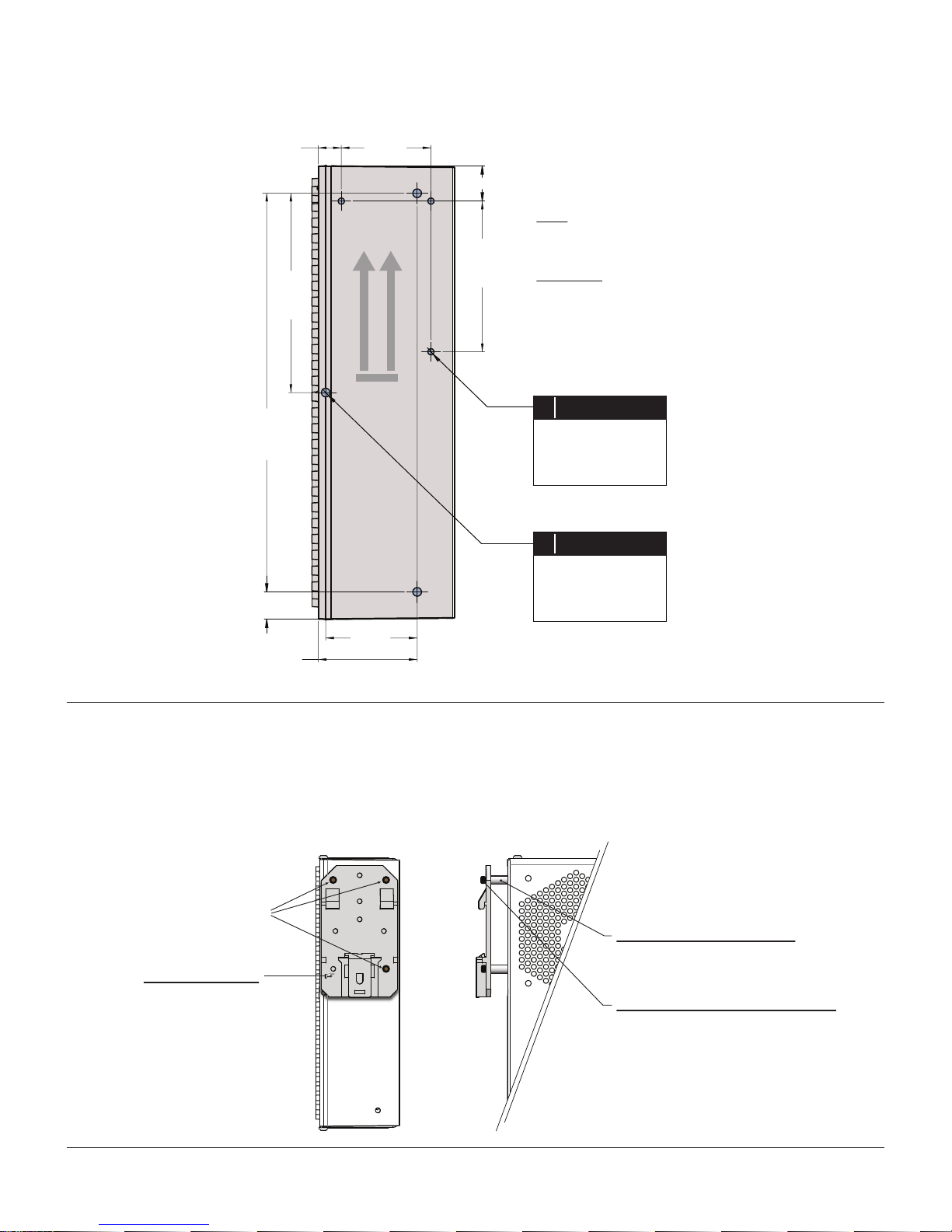
Mounting Hole Dimensions
9.23
Tol. 2
[.363]
80.0
[3.15]
Tol. 1
160.0
[6.3]
Tol. 1
Tol. 1
36.0
[1.417]
A
MOUNT
MOUNT
THIS END UP
THIS END UP
B
Tol. 2
[.557]
B
14.15
A
60.5
[2.382]
Tol. 1
A
Units
mm
[inches]
Tolerances
Tol. 1 =
Tol. 2 =
A
+/- .203 mm
+/- .008 in.
+/- .381 mm
+/- .015 in.
For DIN Rail Clip
*
Dia. 2.50mm [.098”]
Qty. 3, M3 x 0.5 - 6H
Max. penetration into
case = 5.5mm
B
B
[.433]
11.0
Tol. 2
36.7
[1.445]
DIN Rail Adapter
39.7
Tol. 2
[1.563]
(optional, available from third-party)
NOTE: The IPC casting includes holes for mounting the Phoenix Contact UTA-89
DIN rail adapter. If you use this DIN rail adapter, and the DIN rail itself is screwed
to a solid wall or cabinet, you will have to install standoffs as shown below to
provide sufficient clearance for mounting.
Use three mounting screws and
standoffs in indicated positions.
Phoenix PN UTA-89
(also PN 2853970)
DIN Rail Adapter
Tol. 1
A size holes for use with Phoenix UTA-89
*
DIN Rail Adapter. (item not sold by Teknic)
For Direct Mount
Dia. 3.45mm [.136”]
Qty.3, 8-32 UNC-2B
Max. penetration into
case = 0.25 in.
Standoffs, unthreaded (qty. 3)
Metric: Length 10mm, inner diameter >3mm
English: Length 3/8”, inner diameter >3mm
Screws for use with standoffs (qty. 3)
Metric: M3 x 0.5, Class 6H, length: 16-18mm
4
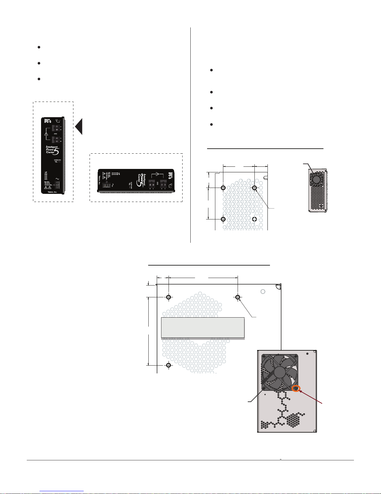
Mounting Orientation Fan Mounting (IPC-5 only)
Mount IPC in one of the orientations shown below. Vertical
mounting improves air flow and is preferable.
Allow minimum 2” clearance above IPC, and at least 1” at
sides and bottom.
Do not mount IPC where ambient temperature exceeds
40ºC.
2”
PREFERRED
MOUNTING
ORIENTATION
1”
1”
2”
1”
1”
1”
Vertical Orientation Horizontal Orientation
1”
The IPC-5 can be optionally equipped with a standard 80 mm or 40
mm case fan, to get up to 40% more continuous power output. If
you intend to use a fan follow, these guidelines:
Use non-conductive hardware to secure fan to case,
such as rubber screws, rubber fan “push pins” or similar
by manufacturers such as Nexus and Lamptron.
Use “open corner” (open frame) style fans for easier
mounting.
Select a fan with medium to high CFM (cubic feet per
minute) rating.
Install fans to exhaust air (draw air out) from case.
Top Mount Fan Mechanical Dimensions
UNITS = mm
16
32
32
13.46
40mm fan
4x Ø 4
IPC-5 shown with optional
40mm (top-mount) fan
40mm
Mounting hole pattern
for 40 mm top-mount fan
Side Mount Fan Mechanical Dimensions
UNITS = mm
12.6
71.5
11.94
NOTE: DO NOT DRILL INTO CASE.
Use only the (3) mounting holes
indicated to attach fan to case.
Mounting hole pattern
for 80mm side-mount fan
71.5
80mm fan
3x Ø 4mm
No screw
here
IPC-5 shown with optional
80 mm (side-mount) fan
5
Specifications
Power
Input Voltage (230 VAC nominal range)
Input Frequency Range
Nominal Output Voltage
Continuous RMS Power Output at 115VAC or 230VAC in;
convection cooled.
225W RMS 0-40°C ambient 350W RMS 0-40°C ambient
Continuous RMS Power Output at 115VAC or 230VAC in; fan
cooled.
N/A 500W RMS 0-40°C ambient
Peak Power Capability at 115VAC or 230VAC in
Peak In-rush Current
Regenerated Energy / Power Absorption 12.7 joules / 13.3 watts RMS at 40°C 19.1 joules / 13.3 watts RMS at 40°C
Capacitive Energy Storage
Allowable (user added) output capacitance
Input Leakage Current
Ripple
Min. equivalent startup load
Output Resistance
Physical
Weight 2.11 lbs. 2.25 lbs.
Dimensions 181mm x 132mm x 57.3mm 183mm x 132mm x 57.3mm
Finger Safe No. User must be protected from shock hazard. Yes
Enclosure None Perforated, epoxy coated steel
Operating Environment
Temperature Range
Humidity
Pollution Level
Acoustic Noise
Certifications/Compliance
Safety
RF Emissions
RoHS
Protective Features
Over-Voltage Protection
Over-Current Protection
Output Short-Circuit Protection
Thermal Overload
Output bus dump load control
Hiccup mode with auto-recovery
Halts power delivery until power removal/reapplication
< 65A
During Regeneration: Initiated at 92VDC, off at 88VDC;
At power-off: Initiated within 200mS of AC power removal, off when output is below ~12VDC
Meets EN55011/22 Class A requirements
Compliant
Halts power delivery until voltage returns to specified output voltage
Hiccup mode with auto-recovery
10% - 90% (non-condensing)
2
50 dB under light or no load, intermittent noise
UL-508C, EN61010
< 500mV P-P, zero to full load
16 ohms @ AC input 105/210V min.
~300 milliohms
0-40°C
900W for 3 sec. (single pulse load at 40°C)
53 joules at 75VDC
10,000 uF maximum
< 500uA @ 250VAC/60Hz
Input Voltage (115 VAC nominal range)
190-250VAC, single phase
108 -125VAC (start under load at ambient temps 0-15°C)
95-125VAC (load independent at ambient temps 15-40°C)
50-60Hz
75VDC ± 0.5V
Power IPC-3 IPC-5
Input Voltage (230 VAC nominal range)
Input Frequency Range
Nominal Output Voltage
Continuous RMS Power Output at 115VAC or 230VAC in;
convection cooled.
225W RMS 0-40°C ambient 350W RMS 0-40°C ambient
Continuous RMS Power Output at 115VAC or 230VAC in; fan
cooled.
N/A 500W RMS 0-40°C ambient
Peak Power Capability at 115VAC or 230VAC in
Peak In-rush Current
Regenerated Energy / Power Absorption 12.7 joules / 13.3 watts RMS at 40°C 19.1 joules / 20 watts RMS at 40°C
Capacitive Energy Storage
Allowable (user added) output capacitance
Input Leakage Current
Ripple
Min. equivalent startup load
Output Resistance
Physical
Weight 2.11 lbs. 2.25 lbs.
Dimensions 181mm x 132mm x 57.3mm 183mm x 132mm x 57.3mm
Finger Safe No. User must be protected from shock hazard. Yes
Enclosure None Perforated, epoxy coated aluminum
Operating Environment
Temperature Range
Humidity
Pollution Level
Acoustic Noise @ 1 distance = meter
Certifications/Compliance
Safety
RF Emissions
RoHS
Protective Features
Over-Voltage Protection
Over-Current Protection
Output Short-Circuit Protection
Thermal Overload
Output bus dump load control
Hiccup mode with auto-recovery
Halts power delivery until power removal/reapplication
< 65A
During Regeneration: Initiated at 92VDC, off at 88VDC;
At power-off: Initiated within 200mS of AC power removal, off when output is below ~12VDC.
Meets EN55011/22 Class A requirements
Compliant
Halts power delivery until voltage returns to specified output voltage
Hiccup mode with auto-recovery
10% - 90% (non-condensing)
2
<50 dBA (variable, dependent on load and AC line)
UL-508C, EN61010
< 500mV P-P, zero to full load
16 ohms @ AC input 105/210V min.
~300 milliohms
0-40°C
900W for 3 sec. (single pulse load at 40°C)
53 joules at 75VDC
10,000 uF maximum
< 500uA @ 250VAC/60Hz
50-60Hz
75VDC ± 0.5V
Input Voltage (115 VAC nominal range)
190-250VAC, single phase
108 -125VAC (start under load at ambient temps 0-15°C)
95-125VAC (load independent at ambient temps 15-40°C)
6
 Loading...